
Create successful ePaper yourself
Turn your PDF publications into a flip-book with our unique Google optimized e-Paper software.
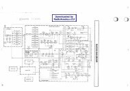
FM DEMODULATOR CIRCUITSIn the FM mode, the filtered 2nd IF signal input frompin 7 is amplified by the internal limiter amplifier, and FMdemodulatedat the internal quadrature detector. Thedemodulated AF signals are then output from pin 11 andapplied to the AF circuits via the AF switch (IC13).AM DEMODULATOR CIRCUITSIn the AM mode, the filtered 2nd IF signal input frompin 5 is amplified by the internal limiter amplifier, and AMdemodulatedat the internal AM detector. The demodulatedAF signals are output from pin 14 and applied to the AF fi ltercircuits via the AF switch (IC13).DIGITAL (DV) DEMODULATOR CIRCUITSIn the DV mode, the filtered 2nd IF signal input frompin 7 is amplified by the internal limiter amplifier, andFM-demodulated at the internal quadrature detector.The demodulated AF signals are applied to the digitaldemodulator circuits via the AF switch (IC13).The FM-demodulated AF signals from the AF switch (IC13)are applied to the modem (IC1012) via the two buffers (IC49b;pins 6, 7 and IC1014), and converted into the digital signal.The converted digital signal is applied to the DSP CODEC(IC1) via the level converter (IC1000, 1001, 1002), to bedecoded into the AMBE signal. The decoded AMBE signal isthen applied to the liner CODEC IC (IC1006) to be convertedinto the analog audio signal. The converted AF signals areapplied to the RX AF circuits.AF FILTER CIRCUITSThe demodulated AF signals are applied to the AF filter(Q47) via the digital/analog signal selector (IC11), to obtainsuitable audio response the for receive mode (FM, AM orDV).The frequency response of the fi lter is controlled by “AFFIL_SEL” signal from the CPU (IC25).The fi ltered AF signals are applied to the variable pass-bandfrequency audio filter circuit (IC49a; pins 3, 1). The circuitreduces audible noises included in the demodulated AFsignals.The fi ltered AF signals are applied to the electric volume IC(IC66) which adjusts the loudness by “AF_VOL_DATA” and“AF_VOL_CK” signals from the CPU (IC25).The level-adjusted AF signals are applied to the AF powerAMP (IC38) via the AF mute SW (Q102).AF POWER AMPLIFIERThe AF signals from the AF mute SW (Q102) are applied tothe AF power AMP (IC38), and amplifi ed to obtain AF outputpower. The power-amplified AF signals are applied to theinternal speaker (CHASSIS; SP1) via J8.If an external speaker is connected to the external speakerjack (J8), the power-amplifi ed AF signals from the AF powerAMP (IC38) are applied to the connected speaker via J8.• DIGITAL (DV) DEMODULATOR CIRCUITSFrom the FM demodulatorcircuits (DV mode)IC49bBUFFIC1014BUFFIC1012MODEM• AF FILTER CIRCUITS AND AF POWER AMPLIFIERIC1000,1001,1002LEVELCNV.IC1006DSPCODECIC1013LINEARCODECTo the AF filter circuits(DV mode)[EXTERNAL SPEAKER JACK]IC38J8AFAM PQ102SPMUTEIC66VolumecontrolSP1AF_VOL_DATAAF_VOL_CKInternal speakerIC49aAFFILTERQ47AFFILTERIC11DIGI/ANSELECTFrom the FM/AM demodulator circuits(FM/AM mode)From the digital demodulator circuits(DV mode)AFFIL_SEL4 - 3