

steady mhd flow of micropolar fluid between two rotating cylinders ...
steady mhd flow of micropolar fluid between two rotating cylinders ...
steady mhd flow of micropolar fluid between two rotating cylinders ...

You also want an ePaper? Increase the reach of your titles
YUMPU automatically turns print PDFs into web optimized ePapers that Google loves.
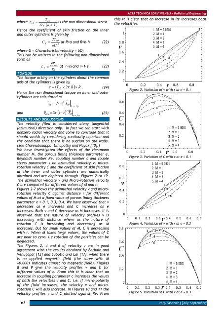
where T118rθTrθ= is the non dimensional stress.Ω2( μ + k )Hence the coefficient <strong>of</strong> skin friction on the innerand outer <strong>cylinders</strong> is given by2TrθC f = at R=a and R=b–h (22)2ρUwhere U = Characteristic velocity = bΩ 2This can be written in the following non-dimensionalform as2TrθC f = at r=r 0 and r=1–e (23)ReTORQUEThe torque acting on the <strong>cylinders</strong> about the commonaxis <strong>of</strong> the <strong>cylinders</strong> is given byτ = ( Trθ × 2π R) × R . (24)Hence the non dimensional torque on inner and outer<strong>cylinders</strong> are calculated asτin20= 2π rand τ 2π ( 1- e)outTrθr = r 02Trθr = 1-e= (25)RESULTS AND DISCUSSIONSThe velocity filed is considered along tangential(azimuthal) direction only. In fact we can start withnonzero radial velocity and come to conclude that itshould vanish by considering continuity equation andthe condition that there is no suction on the walls.(See Channabasappa, Umapathy and Nayak [10].)We have investigated the effects <strong>of</strong> the Hartmannnumber M, the porous lining thickness parameter e,Reynolds number Re, coupling number c and couplestress parameter s on azimuthal velocity v, microrotationvelocity C and the coefficient <strong>of</strong> skin frictionat the inner and outer <strong>cylinders</strong> are numericallyobtained and are depicted through Figures 2 to 19.The azimuthal velocity v and Micro-rotation velocityC are computed for different values <strong>of</strong> M and e.Figures 2–7 shows the azimuthal velocity v and microrotationvelocity C against distance r for differentvalues <strong>of</strong> M at a fixed value <strong>of</strong> porous lining thicknessparameter e = 0.1, 0.3, 0.4. We have observed that vdecreases as e increases and C increases as eincreases. Both v and C decrease as M increases. It isobserved that the nature <strong>of</strong> velocity pr<strong>of</strong>iles v isincreasing with distance where as the nature <strong>of</strong>rotation C is increasing and decreasing as Mincreases. But for small values <strong>of</strong> M, C is decreasingwith r. When M takes large values, the values <strong>of</strong> Care near to zero. i.e rotation <strong>of</strong> the particles can beneglected.The Figures 2, 4 and 6 <strong>of</strong> velocity v are in goodagreement with the results obtained by Bathaih andVenugopal [12] and Subotic and Lai [17], when thereis no applied magnetic field (the curve with M=0.0001 indicates almost no magnetic field). Figures8 and 9 give the velocity pr<strong>of</strong>iles v and C fordifferent values <strong>of</strong> c. From this it is clear that anincrease in coupling parameter c increases the values<strong>of</strong> both the velocities v and C. i.e. if micro-polarity<strong>of</strong> the <strong>fluid</strong> increases, the velocity v and microrotationC will also increase. In Figures 10 and 11 thevelocity pr<strong>of</strong>iles v and C plotted against Re. FromACTA TECHNICA CORVINIENSIS – Bulletin <strong>of</strong> Engineeringthis it is clear that an increase in Re increases boththe velocities.Figure 2. Variation <strong>of</strong> v with r at e = 0.1Figure 3. Variation <strong>of</strong> C with r at e = 0.1Figure 4. Variation <strong>of</strong> v with r at e = 0.3Figure 5. Variation <strong>of</strong> C with r at e = 0.32013. Fascicule 3 [July–September]


