Organization and Control of Autonomous Railway Convoys
Organization and Control of Autonomous Railway Convoys
Organization and Control of Autonomous Railway Convoys

Create successful ePaper yourself
Turn your PDF publications into a flip-book with our unique Google optimized e-Paper software.
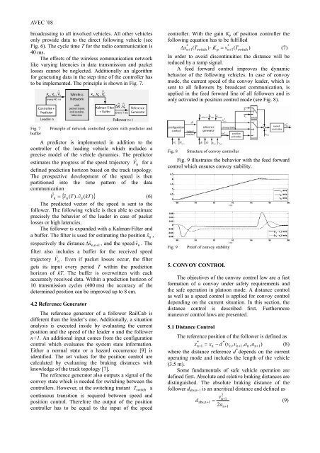
AVEC ’08broadcasting to all involved vehicles. All other vehiclesonly provide data to the direct following vehicle (seeFig. 6). The cycle time T for the radio communication is40 ms.The effects <strong>of</strong> the wireless communication networklike varying latencies in data transmission <strong>and</strong> packetlosses cannot be neglected. Additionally an algorithmfor generating data in the step time <strong>of</strong> the controller hasto be implemented. The principle is shown in Fig. 7.controller. With the gain K p <strong>of</strong> position controller thefollowing equation has to be fulfilled**∆ x n+ 1( Tswitch) ⋅ Kp= vn+1(Tswitch)(7)In order to avoid discontinuities the distance will bereduced by a ramp signal.A feed forward control improves the dynamicbehavior <strong>of</strong> the following vehicles. In case <strong>of</strong> convoymode, the current speed <strong>of</strong> the convoy leader, which issent to all followers by broadcast communication, isapplied in the feed forward line <strong>of</strong> all followers <strong>and</strong> isonly activated in position control mode (see Fig. 8).Fig. 7bufferPrinciple <strong>of</strong> network controlled system with predictor <strong>and</strong>A predictor is implemented in addition to thecontroller <strong>of</strong> the leading vehicle which includes aprecise model <strong>of</strong> the vehicle dynamics. The predictorestimates the progress <strong>of</strong> the speed trajectory V ˆ n for adefined prediction horizon based on the track topology.The prospective development <strong>of</strong> the speed is thenpartitioned into the time pattern <strong>of</strong> the datacommunicationV ˆn = { vˆn ( T )..ˆ vn( kT )}(6)The predicted vector <strong>of</strong> the speed is sent to thefollower. The following vehicle is then able to estimateprecisely the behavior <strong>of</strong> the leader in case <strong>of</strong> packetlosses or high latencies.The follower is exp<strong>and</strong>ed with a Kalman-Filter <strong>and</strong>a buffer. The filter is used for estimating the position ˆx n ,respectively the distance ∆x ˆn,n+1 , <strong>and</strong> the speed ˆv n . Thefilter also includes a buffer for the received speedtrajectory Vˆ n . Even if packet losses occur, the filtergets its input every period T within the predictionhorizon <strong>of</strong> kT. The buffer is overwritten with eachaccurately received data. Within a prediction horizon <strong>of</strong>10 transmission cycles (400 ms) the accuracy <strong>of</strong> thedetermined position can be improved up to 8 cm.4.2 Reference GeneratorThe reference generator <strong>of</strong> a follower RailCab isdifferent than the leader’s one. Additionally, a situationanalysis is executed inside by evaluating the currentposition <strong>and</strong> the speed <strong>of</strong> the leader n <strong>and</strong> the followern+1. An additional input comes from the configurationcontrol which evaluates the system state information.Either a normal state or a hazard occurrence [9] isidentified. The set values for the position control arecalculated by evaluating the braking distances withknowledge <strong>of</strong> the track topology [7].The reference generator also outputs a signal <strong>of</strong> theconvoy state which is needed for switching between thecontrollers. However, at the switching instant T switch acontinuous transition is required between speed <strong>and</strong>position control. Therefore the output <strong>of</strong> the positioncontroller has to be equal to the input <strong>of</strong> the speedFig. 8Structure <strong>of</strong> convoy controllerFig. 9 illustrates the behavior with the feed forwardcontrol which ensures convoy stability.Fig. 9Pro<strong>of</strong> <strong>of</strong> convoy stability5. CONVOY CONTROLThe objectives <strong>of</strong> the convoy control law are a fastformation <strong>of</strong> a convoy under safety requirements <strong>and</strong>the safe operation in platoon mode. A distance controlas well as a speed control is applied for convoy controldepending on the current situation. In this section, thedistance control is described first. Furthermoremaneuver control laws are presented.5.1 Distance <strong>Control</strong>The reference position <strong>of</strong> the follower is defined as* *x n + 1 = xn− d ( vn, vn+ 1,an, an+ 1)(8)where the distance reference d * depends on the currentoperating mode <strong>and</strong> includes the length <strong>of</strong> the vehicle(3.5 m).Some fundamentals <strong>of</strong> safe vehicle operation aredefined first. Absolute <strong>and</strong> relative braking distances aredistinguished. The absolute braking distance <strong>of</strong> thefollower d abs,n+1 is an uncritical distance <strong>and</strong> defined as2vn+12 n + 1d abs,n+ 1 = (9)a

![[ ] Ï - Fachgebiet Leistungselektronik und Elektrische Antriebstechnik](https://img.yumpu.com/51151382/1/184x260/-i-fachgebiet-leistungselektronik-und-elektrische-antriebstechnik.jpg?quality=85)