ARB 4x4 ACCESSORIES - CARiD.com
ARB 4x4 ACCESSORIES - CARiD.com
ARB 4x4 ACCESSORIES - CARiD.com

Create successful ePaper yourself
Turn your PDF publications into a flip-book with our unique Google optimized e-Paper software.
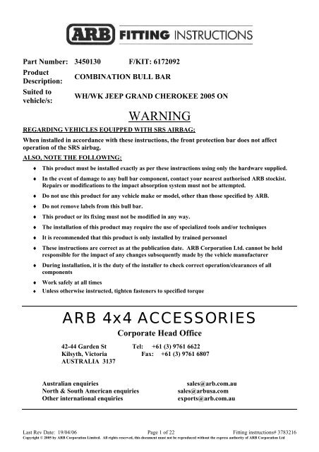
Part Number: 3450130 F/KIT: 6172092ProductDescription:Suited tovehicle/s:COMBINATION BULL BARWH/WK JEEP GRAND CHEROKEE 2005 ONWARNINGREGARDING VEHICLES EQUIPPED WITH SRS AIRBAG;When installed in accordance with these instructions, the front protection bar does not affectoperation of the SRS airbag.ALSO, NOTE THE FOLLOWING:♦ This product must be installed exactly as per these instructions using only the hardware supplied.♦ In the event of damage to any bull bar <strong>com</strong>ponent, contact your nearest authorised <strong>ARB</strong> stockist.Repairs or modifications to the impact absorption system must not be attempted.♦ Do not use this product for any vehicle make or model, other than those specified by <strong>ARB</strong>.♦ Do not remove labels from this bull bar.♦ This product or its fixing must not be modified in any way.♦ The installation of this product may require the use of specialized tools and/or techniques♦ It is re<strong>com</strong>mended that this product is only installed by trained personnel♦ These instructions are correct as at the publication date. <strong>ARB</strong> Corporation Ltd. cannot be heldresponsible for the impact of any changes subsequently made by the vehicle manufacturer♦ During installation, it is the duty of the installer to check correct operation/clearances of all<strong>com</strong>ponents♦ Work safely at all times♦ Unless otherwise instructed, tighten fasteners to specified torque<strong>ARB</strong> <strong>4x4</strong> <strong>ACCESSORIES</strong>Corporate Head Office42-44 Garden St Tel: +61 (3) 9761 6622Kilsyth, Victoria Fax: +61 (3) 9761 6807AUSTRALIA 3137Australian enquiriesNorth & South American enquiriesOther international enquiriessales@arb.<strong>com</strong>.ausales@arbusa.<strong>com</strong>exports@arb.<strong>com</strong>.auLast Rev Date: 19/04/06 Page 1 of 22 Fitting instructions# 3783216Copyright © 2005 by <strong>ARB</strong> Corporation Limited. All rights reserved, this document must not be reproduced without the express authority of <strong>ARB</strong> Corporation Ltd
www.arb.<strong>com</strong>.auGENERAL CARE AND MAINTENANCEBy choosing an <strong>ARB</strong> Bar, you have bought a product that is one of the most sought after 4WD productsin the world. Your bar is a properly engineered, reliable, quality accessory that represents excellentvalue. To keep your bar in original condition it is important to care and maintain it following thesere<strong>com</strong>mendations.• Prior to exposure to the weather your bar should be treated to a Canuba based polish on all exposedsurfaces. It is re<strong>com</strong>mended that this is performed on a six monthly basis or following exposure tosalt, mud, sand or other contaminants.• As part of any Pre Trip Preparation, or on an annual basis, it is re<strong>com</strong>mended that a thorough visualinspection of the bar is carried out, making sure that all bolts and other <strong>com</strong>ponents are torqued to thecorrect specification. Also check that all wiring sheaths, connectors, and fittings are free of damage.Replace any <strong>com</strong>ponents as necessary. This service can be performed by your local authorized <strong>ARB</strong>stockist.HAVE AVAILABLE THESE SAFETY ITEMS WHEN FITTING PRODUCT:BASIC TOOL KITKEY HOLE SAWProtective eyewearHearing protectionNOTE: ‘WARNING’ notes in the fitting procedure relate to OHS situations, where to avoid a potentiallyhazardous situation it is suggested that protective safety gear be worn or a safe work procedure be employed. Ifthese notes and warnings are not heeded, injury may result.FASTENER TORQUE SETTINGS:SIZE Torque Nm Torque lbftM6 9Nm 4lbftM8 22Nm 16lbftM10 44Nm 32lbftM12 77Nm 57lbftNOTE: IF YOUR VEHICLE IS NOT FITTED WITH FOG LIGHTSYOU CAN PURCHASE A FOG LIGHT KIT FROM JEEP PART NO. 82209301Last Rev Date: 19/04/06 Page 2 of 22 Fitting instructions# 3783216Copyright © 2005 by <strong>ARB</strong> Corporation Limited. All rights reserved, this document must not be reproduced without the express authority of <strong>ARB</strong> Corporation Ltd
.USE PART No QTY DESCRIPTION6151357 8 BOLT M10 x 1.5 x 30mm SEMS ASSY6151090 2 BOLT M10 X 1.25 X 50mm6151133 2 NUT M10 X 1.25IMPACT ABSORBER 4581040 4 WASHER FLAT M10MOUNTING SYSTEM 4581048 4 WASHER SPRING M106151304 8 NUT CAGED M103756904 1 MOUNT ASSEMBLY5848328 2 PACKER MOUNT ASSY4601172 L/R 2 CHANNEL CAPTIVE NUT (INSIDE CHASSIS RAILS)3199854 2 PLATE CAPTIVE NUT (CROSSMEMBER TO CHASSIS)6151291 2 BOLT M12 X 1.25 X 30mm (WITH EXTENSION PLATE)6151133 2 NUT M10 X 1.254581049 4 WASHER FLAT M124581050615113561511804581082458103622222WASHER SPRING M12NUT M12 X1.25BOLT M6 x 20M6 FLAT WASHERM6 SPRING WASHERBULL BAR TO 6151357 8 BOLT M10 x 30mm SEMS ASSYIMPACT ABSORBERS 6151304 6 NUT CAGED M104581040 2 WASHER FLAT M106151026 2 NUT M10 X 1.56151021 2 BOLT M8 x 20mmCONTROL BOX BRACKET 4581046 2 WASHER FLAT M83751564 1 CONTROL BOX BRACKET6151132 2 NUT FLANGE M8NUMBER PLATE BRACKET 6151180 2 BOLT M6 x 20mm (BRACKET TO BAR)6151046 4 WASHER FLAT M6 x 13mm6151128 4 NUT FLANGE M66151180 2 BOLT M6 x 20mm (NUMBER PLATE TO BRACKET)3751370 1 NUMBER PLATE BRACKETTO BOLT INDICATORS TO 6821151L 1 INDICATORBAR 6821151R 1 INDICATOR6821152 2 LOOM INDICATOR6151308 4 SCREW SELF TAPPING 256821116 4 GROMMET NYLON SNAP IN TYPE180701 6 SCOTCH LOCKS3162466 L/R 2 BUFFERS 260 X 230 UPRIGHT B/B<strong>ARB</strong>UFFERS 6151128 12 NUT FLANGE M6AIR DEFLECTOR 6522662 1 AIR DEFLECTOR6151262 3 BOLT M8 X 20mm BLACK6151303 3 NUT CAGED M8 BLACK4581045 3 WASHER FLAT M8 x 20mm4581047 3 WASHER SPRING M8 BLACK6522663 L/R 2 PANELSUNDER WING PANEL 6151213 10 BOLT M6 x 20mm BLACK4581082 10 WASHER FLAT M6 BLACK4581287 10 WASHER SPRING M6 BLACK6151128 2 NUT FLANGE M66151300 8 NUT CAGED M6FOG LIGHT HOUSING 3162457 1 PLASTIC HOUSING RHSAND FITMENT 3162456 1 PLASTIC HOUSING LHS6821184 1 LOOM ( CABLE RED ) (CUT INTO 4 EQUAL LENGTHS )180701 8 SCOTCH LOCKSINNER GUARD TO BAR 6151213 4 BOLT M6 x 20mm BLACK4581082 4 WASHER FLAT M6 x 20mm BLACK6151128 4 NUT FLANGE M64581287 4 WASHER SPRING M6180302 2 CABLE TIESWINCH FITMENT 180302 8 CABLE TIES6151073 2 BOLT 3/8” X 1 ½”6151074 2 BOLT 3/8” X 1 ¾”4581040EG5042WASHER FLAT M10RUBBER GROMMETLast Rev Date: 19/04/06 Page 3 of 22 Fitting instructions# 3783216Copyright © 2005 by <strong>ARB</strong> Corporation Limited. All rights reserved, this document must not be reproduced without the express authority of <strong>ARB</strong> Corporation Ltd
ASSEMBLY SEQUENCE FOR BULL BAR INSTALLATION.PLEASE READ AND UNDERSTAND FITTING INSTRUCTIONS BEFOREATTEMPTING TO FIT BAR TO VEHICLE1. Remove grille from vehicle byremoving all plastic clipsBe careful when removing plasticclips from grille as the plastic clipsare awkward to undo and will bere used when refitting grille.Slide flat blade screw driver underpin of plastic clip and remove pin,then lift out the plastic clip.When all clips are removed, pullgrill upward toward you.GRILLE RETAINER PANEL2. Remove lower plastic grilleretainer panel from vehicle and putaside, as this panel will have to bemodified later.Remove tow hook and crush cansfrom vehicleLast Rev Date: 19/04/06 Page 4 of 22 Fitting instructions# 3783216Copyright © 2005 by <strong>ARB</strong> Corporation Limited. All rights reserved, this document must not be reproduced without the express authority of <strong>ARB</strong> Corporation Ltd
3. To remove bumper bar wherethe inner guard is attached, pushplastic pin inward , then pull outplastic retainer clip. Remove foglights and fog light adjuster andthe black plastic grommets frombumper.4. To remove headlights fromvehicle for ease of joining indicatorlooms and extending fog lightlooms, firstly lift plastic cover fromabove headlight and undo oneplastic retaining clip and three6mm bolts, then remove headlights.5. After removing headlights fromvehicle, remove some of the blueinsulating tape from vehicleindicator and parking looms toexpose wiring to be able to fitconnectors.Last Rev Date: 19/04/06 Page 5 of 22 Fitting instructions# 3783216Copyright © 2005 by <strong>ARB</strong> Corporation Limited. All rights reserved, this document must not be reproduced without the express authority of <strong>ARB</strong> Corporation Ltd
6. Use scotch locks to connect wiring.Summary of Wire ConnectionsFUNCTIONTURNSIGNALHARNESSVEHICLE PARK LAMPRIGHT LEFTPARK LAMP RED BLACK / PINK BLACK / PINKVEHICLE INDICATORRIGHT LEFTEARTH BLACK BLACK BLACKINDICATOR GREEN GREEN GREEN7. Test all lighting at this stage.8 . To refit fog lights to bar, theloom must be extended.9. Cut the fog light loom in halfand then cut the 1.3 metre redwire, ( supplied in bar fitting kit )into four equal lengths ( i.e.325mm each )Last Rev Date: 19/04/06 Page 6 of 22 Fitting instructions# 3783216Copyright © 2005 by <strong>ARB</strong> Corporation Limited. All rights reserved, this document must not be reproduced without the express authority of <strong>ARB</strong> Corporation Ltd
10. Scotch lock the red wire inbetween the fog light loom makingsure the colour code matches.11. When all wiring is <strong>com</strong>pleted.Refit headlights back into vehicle.12. Next step is to cut grilleretainer panel so bar can be fitted.13. From the photo below markout a parallel line of 45mm andcut off panel not required using ajig saw or a key hole saw, thenrefit back to vehicle.REFER TO PARAGRAPH 2 FORPANEL IDENTIFICATIONPHOTO OF REFITTED PANEL OFLEFT CORNER OF VEHICLE14. Fit M10 caged nuts intochannel ( channels are L/RHS )then fit channels inside of chassisrailsNotch in channel must face inwardLast Rev Date: 19/04/06 Page 7 of 22 Fitting instructions# 3783216Copyright © 2005 by <strong>ARB</strong> Corporation Limited. All rights reserved, this document must not be reproduced without the express authority of <strong>ARB</strong> Corporation Ltd
15. Using a 6mm drill bit, drilltwo holes approximately 50mmapart through the plastic innerguard and the outer edge of theplastic splash panel.16. Cable tie these two panelstogetherPHOTO IS OF RHS OF VEHICLE17. Remove alarm device from RHSof crossmember by unscrewingtwo 6mm bolts18. Replace this part when chassismount assembly is fitted.ARROWS INDICATE BOLTSTO BE REMOVED19. Lift chassis mount assembly ontovehicle crossmember.20. Using black M6mm x 20 bolt ,spring / flat washer, secure tovehicle as per photo.21. Make sure mount assembly islifted up hard against bottom ofchassis rails, then tighten 6mmbolts. ( These bolts are only toposition mount assembly tovehicle.Last Rev Date: 19/04/06 Page 8 of 22 Fitting instructions# 3783216Copyright © 2005 by <strong>ARB</strong> Corporation Limited. All rights reserved, this document must not be reproduced without the express authority of <strong>ARB</strong> Corporation Ltd
22. As viewed from underneath onLHS of vehicle, align rear hole ofmount assembly to previouslyfitted captive nut channel, secureusing M10 bolt x 30mm SEMS (Bolt, Spring and Flat WasherASSY. )23. Finger tighten only.24. Carry out fixing to both sides ofvehicle.NOTE: ‘WARNING’ notes in thefitting procedure relate to OHSsituations, where to avoid a potentiallyhazardous situation it is suggested thatprotective safety gear be worn or a safework procedure be employed. If thesenotes and warnings are not heeded,injury may result.25. Using a 10mm drill bit, drill holethrough chassis rail,using hole inmount as a template. Be carefulnot to drill into the nut in captivenut channel.26. Secure using bolts same as above,when all four bolts are fitted,tighten securely.Last Rev Date: 19/04/06 Page 9 of 22 Fitting instructions# 3783216Copyright © 2005 by <strong>ARB</strong> Corporation Limited. All rights reserved, this document must not be reproduced without the express authority of <strong>ARB</strong> Corporation Ltd
27. Using holes in chassis mountassembly as a template, drillthrough crossmember on bothsides using 10mm drill bit.Warning: Drilling operations can result in flyingmetal debris, safety glasses should be worn.28. Also drill through top of mountinto vehicle crossmember,making sure that you are drillingperpendicular.Warning: Drilling operations can result in flyingmetal debris, safety glasses should be worn.29. Fit packer in between mountassembly and vehiclecrossmember and align with thetwo holes.Viewed from above on LHS of vehicleLast Rev Date: 19/04/06 Page 10 of 22 Fitting instructions# 3783216Copyright © 2005 by <strong>ARB</strong> Corporation Limited. All rights reserved, this document must not be reproduced without the express authority of <strong>ARB</strong> Corporation Ltd
30. Fit M10 caged nuts into captivenut plate, then align withpreviously drilled front holes.31. Secure using M10 bolts (SEMS)finger tighten only.LHS OF VEHICLEVIEWED FROM LHS32. Insert M12 Tagged bolt / flatwasher into the chassis rail andpass through 12mm hole inchassis rail.33. Fit through hole in captive nutplate and secure with flat , springwasher and 12mm nut.34. Finger tighten only1135. Fit a M10 bolt x 50mm (finethread) and a flat washer up frominside chassis rails, throughpacker and chassis mount assyand secure with a flat, springwasher and 10mm nut.36. At this stage all bolts are fitted tovehicle. Know they can all betightened.Last Rev Date: 19/04/06 Page 11 of 22 Fitting instructions# 3783216Copyright © 2005 by <strong>ARB</strong> Corporation Limited. All rights reserved, this document must not be reproduced without the express authority of <strong>ARB</strong> Corporation Ltd
37. Tighten this 12mm bolt eachside using universal joint and ½”drive extension.38. Refit alarm device at this stage.39. Fit nylon grommets into squareholes to mount indicator / parkerlampsLast Rev Date: 19/04/06 Page 12 of 22 Fitting instructions# 3783216Copyright © 2005 by <strong>ARB</strong> Corporation Limited. All rights reserved, this document must not be reproduced without the express authority of <strong>ARB</strong> Corporation Ltd
40. Remove the fastening screwsand nuts supplied with the turnsignal/clearance lamps and replacethese with the four screws providedin the kit. Fasten the lamps to thebar as shown.IMPORTANTThe turn signal is to the inside ofthe bar.41. Fit M10 caged nuts to inside ofmounting face of bar.Viewed from the RHS of the inside of bar42. If bar is to have a winch fitted,follow the next steps.43. Fit number plate bracket using6mm hardware (20mm x 6mbolts )44. Fit control box bracket to barusing 8mm hardware.( 20 x 8mm )45. Fit rubber grommets to top ofbar.Last Rev Date: 19/04/06 Page 13 of 22 Fitting instructions# 3783216Copyright © 2005 by <strong>ARB</strong> Corporation Limited. All rights reserved, this document must not be reproduced without the express authority of <strong>ARB</strong> Corporation Ltd
46. Drill 12mm holes under existingholes 25mm lower down the samepitch as existing holes, these will bethe holes used to bolt roller fairleadto bar.NEW HOLESWarning: Drilling operations can result in flyingmetal debris, safety glasses should be worn.47. Fit buffers to bar using 6mmflange nuts.VIEWED FROM BEHIND BAR LHS48. To fit winch into bar you mustpack winch up on a bench to enableyou to lower bar down on winch,then fit four 3/8 ” square nuts intowinch lugs.Last Rev Date: 19/04/06 Page 14 of 22 Fitting instructions# 3783216Copyright © 2005 by <strong>ARB</strong> Corporation Limited. All rights reserved, this document must not be reproduced without the express authority of <strong>ARB</strong> Corporation Ltd
49. Lower bar down over winch,line up top holes first and secureusing 3/8” hardware (1 ½”” x3/8”bolts) flat and spring washers.50. Place roller fairlead over lowerholes and again secure using 3/8”hardware (1 ¾”x 3/8” bolts) flat andspring washers. When all bolts arefitted tighten firmly.51. Fit control box to control boxbracket using original ¼” nutsfrom control box and connectpower cables to winch as per winchinstructions.52. Cable tie power cables clear ofsharp edges and all moving parts.53. Fit control box earth to winchtie rods.Last Rev Date: 19/04/06 Page 15 of 22 Fitting instructions# 3783216Copyright © 2005 by <strong>ARB</strong> Corporation Limited. All rights reserved, this document must not be reproduced without the express authority of <strong>ARB</strong> Corporation Ltd
54. Fit M8 caged nuts ( 3 OF ) intolower section of bar.( These nuts are to attached airdeflector pan to bar later on. )55. Fit bar in between chassismounting assembly, align slots inbar to caged nuts in mountingassembly and secure using M10bolts ( sems ) assy.56. Adjust bar to vehicle andtighten all bolts using socket,extension and uni joint through foglight aperture in bar.57. Bar should have a 10-15mm gapbetween bar surround and guardline.Last Rev Date: 19/04/06 Page 16 of 22 Fitting instructions# 3783216Copyright © 2005 by <strong>ARB</strong> Corporation Limited. All rights reserved, this document must not be reproduced without the express authority of <strong>ARB</strong> Corporation Ltd
58. Once the bar is secured tovehicle, using holes in lowersection of bar as a template, drill10mm holes through mountingassembly and fix using 10mmhardware.(This bolt locks the bar to mountingassembly. )Warning: Drilling operations can result in flyingmetal debris, safety glasses should be worn.59. Using 6mm hardware, secureplastic inner guard to top hole inbar.60. To secure lower hole, drill a6mm hole through inner guardaligning with hole in bar.61. Next is to fit wing panels, firstlyfit M6 caged nuts to outer edgesof panel.PHOTO IS OF LHS OF VEHICLEARROW INDICATESTEMPLATE DRILLING HOLE.Last Rev Date: 19/04/06 Page 17 of 22 Fitting instructions# 3783216Copyright © 2005 by <strong>ARB</strong> Corporation Limited. All rights reserved, this document must not be reproduced without the express authority of <strong>ARB</strong> Corporation Ltd
62. Fit panel on top of wing returnsand secure using 6mm hardware.USE BLACK 6MM HARDWARE63. Drill a 6mm hole into plasticvehicle splash pan using hole inwing panel as a template.64. Secure using 6mm hardware.Warning: Drilling operations can result in flyingmetal debris, safety glasses should be worn.SEE PARAGRAPH 61 FORHOLE LOCATION65. After under wing panels areall bolted up, using a key hole sawetc, cut off the plastic under guardwhich protrudes past the panels.66. Dress up with a file.Last Rev Date: 19/04/06 Page 18 of 22 Fitting instructions# 3783216Copyright © 2005 by <strong>ARB</strong> Corporation Limited. All rights reserved, this document must not be reproduced without the express authority of <strong>ARB</strong> Corporation Ltd
67. Undo the three 6mm bolts asper photo so air deflector pan canfit in between.67. Fit front of air deflector tounderside of bar using black8mm hardware.68. Fit rear of air deflector usingoriginal 6mm bolts. (refer toparagraph 67.69. If no fog lights are not going tobe fitted, fit light surround tobar as is. If fog lights are goingto be fitted, cut out rear ofsurround using a key hole sawand remove rough edges with afile.Last Rev Date: 19/04/06 Page 19 of 22 Fitting instructions# 3783216Copyright © 2005 by <strong>ARB</strong> Corporation Limited. All rights reserved, this document must not be reproduced without the express authority of <strong>ARB</strong> Corporation Ltd
70. Light surround is held to barusing silicon.71. Apply a bead of siliconaround light cutout on bar andhold fog light housing to barusing masking tape until silicondries, then remove tape.72. If fitting fog lights back intovehicle, pull extended loomthrough fog light mountingbracket and refit black plasticgrommets back into square hole.73. Reconnect fog light plug backinto light.74 .Smear grease onto the lightmounting pivots to help whensliding fog light back intomounting bracket.75. NB. When fitting light intobracket, you must rotate light soplug fits in between rear ofbracket and vehicle crossmember,then push light rearward untillight click into bracket mountingholes.Last Rev Date: 19/04/06 Page 20 of 22 Fitting instructions# 3783216Copyright © 2005 by <strong>ARB</strong> Corporation Limited. All rights reserved, this document must not be reproduced without the express authority of <strong>ARB</strong> Corporation Ltd
76. When light is fitted to bracketrefit adjuster screw then reset lightalignment.IF YOUR VEHICLE IS NOTFITTED WITH FOG LIGHTS,YOU CAN PURCHASE A FOGLIGHT KIT FROM JEEP.Part no. 82209301.77. Follow steps to fit light housingto bar same as paragraph 71.NB. Photo shows silicon appliedaround fog light cutout.OPTIONAL COLOUR CODE HOUSING78. Position for Hi lift jackingpoint.Last Rev Date: 19/04/06 Page 21 of 22 Fitting instructions# 3783216Copyright © 2005 by <strong>ARB</strong> Corporation Limited. All rights reserved, this document must not be reproduced without the express authority of <strong>ARB</strong> Corporation Ltd
79. The Warn roller fairlead covermust be fitted to roller fairleadwhen winch is not in use due toprotruding sharp edgeslegislation.Warn Part no. W2558080. The cover requires thelower side profile to be cut to fitthe bar centre section profile.PHOTO SHOWS COLOUR CODED BARLast Rev Date: 19/04/06 Page 22 of 22 Fitting instructions# 3783216Copyright © 2005 by <strong>ARB</strong> Corporation Limited. All rights reserved, this document must not be reproduced without the express authority of <strong>ARB</strong> Corporation Ltd