High-quality Smart-pig Inspection of Dents - ROSEN Inspection ...
High-quality Smart-pig Inspection of Dents - ROSEN Inspection ...
High-quality Smart-pig Inspection of Dents - ROSEN Inspection ...

You also want an ePaper? Increase the reach of your titles
YUMPU automatically turns print PDFs into web optimized ePapers that Google loves.
2<br />
Technology & Services Section<br />
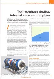
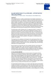
Figure 1: <strong>High</strong>-<strong>quality</strong> Geometry Unit (XGP) in Combination with Different<br />
<strong>High</strong>-resolution Metal Loss <strong>Inspection</strong> and Crack <strong>Inspection</strong> Tools<br />
From left to right: ECD+XGP, AFD+XGP, CDP+XGP and XGP.<br />
Introducing a high-<strong>quality</strong> in-line inspection process<br />
for dents and mechanical damage can provide the<br />
basis information, such as the geometric data <strong>of</strong> dents<br />
and stress risers, to start a managed integrity process<br />
for the inspected line. The more high-resolution and<br />
high-<strong>quality</strong> information that is available about the<br />
anomaly found, the better the subsequent failure<br />
analyses can be.<br />
It is important not only to size and describe the<br />
dents with high accuracy, but also to detect and<br />
characterise the mentioned stress risers. State-<strong>of</strong>-theart<br />
equipment for characterisation <strong>of</strong> the stress riser<br />
are high-resolution ILI tools based on the magnetic<br />
flux leakage principle (MFL), circumferential MFL<br />
tools or the recently developed Electro Magnetic<br />
Acoustic Transducer (EMAT) Crack Detection<br />
(ECD) tool based on electromagnetic coupled<br />
ultrasound. In addition, or more preferable in<br />
combination with one <strong>of</strong> those tools, a highresolution<br />
Geometry Pig (XGP) rendering the pipe<br />
shell in space must be used (see Figure 1).<br />
Circumferential Resolution and<br />
Coverage<br />
The performance <strong>of</strong> a geometry inspection<br />
configuration for dents can be estimated using an<br />
analytical model. According to the model the<br />
sizing accuracy and the POD for dents can be<br />
determined as a function <strong>of</strong> the circumferential<br />
resolution and the coverage <strong>of</strong> the sensing area <strong>of</strong><br />
the caliper sensors.<br />
The decisive parameter for the POD is mainly the<br />
coverage <strong>of</strong> the caliper sensor in circumferential<br />
direction. A geometry tool like the established<br />
<strong>ROSEN</strong> Electronic Geometry Pig (EGP) with a<br />
circumferential coverage <strong>of</strong> 100% would perform<br />
with an analytical POD <strong>of</strong> one for the three types <strong>of</strong><br />
dents. The 100% coverage is achieved with the<br />
touchless operating sensor unit. Another example is<br />
the simple caliper tool, equipped with 12 caliper<br />
arms and a typical coverage <strong>of</strong> 55%. The POD in this<br />
case is reduced to 0.75 for a sharp dent <strong>of</strong> 0.32 inches<br />
(8.1mm) depth (2% improved detection). Again, this<br />
indicates the importance <strong>of</strong> coverage.<br />
Another effect that can be studied is the systematical<br />
undersizing <strong>of</strong> dents as a function <strong>of</strong> circumferential<br />
resolution and coverage. Assuming that a dent is not<br />
hit at the tip by a caliper or scanning sensor, the<br />
maximum possible undersizing <strong>of</strong> the dent depth can<br />
be calculated for a geometry inspection configuration.<br />
The maximum possible undersizing <strong>of</strong> the dent, in<br />
comparison with the real depth, is plotted versus the<br />
circumferential coverage for a different number <strong>of</strong><br />
caliper arms. It can be seen that an increase <strong>of</strong> caliper<br />
arms improves the sizing difference. Nevertheless,<br />
coverage close to 100% is the strongest parameter to<br />
achieve an accurate depth measurement.<br />
The maximum coverage a geometry inspection tool<br />
with a single plane <strong>of</strong> caliper sensors will achieve is<br />
close to the bore reduction a tool can negotiate,<br />
typically reduced by approximately 15% (due to<br />
required mechanical tolerances). Therefore, a<br />
typical value <strong>of</strong> 75% passage leads to a maximum<br />
coverage <strong>of</strong> 60%.<br />
The circumferential resolution determines the<br />
parameterisation capabilities for geometric<br />
anomalies. Recent studies did show that a ‘dent<br />
acuity’ <strong>of</strong> 0.1d/w must be resolved (acuity=2d/w,<br />
where d=dent depth and w=dent width) 1 .<br />
Including the previously mentioned depth<br />
threshold <strong>of</strong> 0.25 inches (6.35mm), a dent <strong>of</strong> 5<br />
inches (127mm) wide has to be resolved.<br />
Based on these theoretical considerations, a geometry<br />
inspection configuration is desired with an acceptable<br />
total circumferential resolution e.g. < 2 inches<br />
(50.8mm) and caliper sensors arranged in two axially<br />
separated planes governing a possible circumferential<br />
coverage <strong>of</strong> more than 95%.<br />
Mechatronic Principle<br />
Other issues, beside the requirements derived from<br />
the preceding analytical considerations and the<br />
regulatory demands highlighted, have to be<br />
considered for the conceptual design <strong>of</strong> a geometry<br />
inspection tool.<br />
A disadvantage <strong>of</strong> the traditional mechanical caliper<br />
tool design, where the mechanical movement <strong>of</strong> the<br />
caliper is transformed into a position signal, is the<br />
dynamic behaviour <strong>of</strong> the arms under ‘run’<br />
conditions. This typically leads to inspection speed<br />
BUSINESS BRIEFING: OIL & GAS PROCESSING REVIEW 2005