in-line inspection of co2 pipelines - ROSEN Inspection Technologies
in-line inspection of co2 pipelines - ROSEN Inspection Technologies
in-line inspection of co2 pipelines - ROSEN Inspection Technologies

Create successful ePaper yourself
Turn your PDF publications into a flip-book with our unique Google optimized e-Paper software.
Document Name <strong>ROSEN</strong> CO2 - F<strong>in</strong>al Paper 01_20110614<br />
Revision Date 21-Sep-11<br />
Empowered by Technology<br />
www.rosen<strong>in</strong>spection.net<br />
IN-LINE INSPECTION OF CO2 PIPELINES – OPPORTUNITIES<br />
AND CHALLENGES<br />
Jochen Spal<strong>in</strong>k, Dr. Hubert L<strong>in</strong>dner, Thomas Beuker <strong>of</strong> the <strong>ROSEN</strong> Group<br />
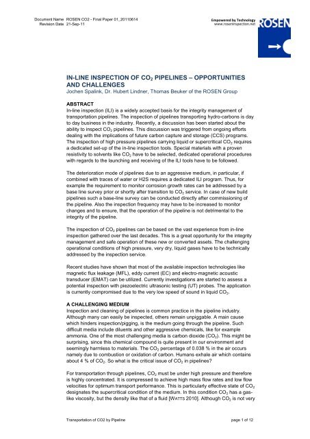
ABSTRACT<br />
In-l<strong>in</strong>e <strong>in</strong>spection (ILI) is a widely accepted basis for the <strong>in</strong>tegrity management <strong>of</strong><br />
transportation pipel<strong>in</strong>es. The <strong>in</strong>spection <strong>of</strong> pipel<strong>in</strong>es transport<strong>in</strong>g hydro-carbons is day<br />
to day bus<strong>in</strong>ess <strong>in</strong> the <strong>in</strong>dustry. Recently, a discussion has been started about the<br />
ability to <strong>in</strong>spect CO 2 pipel<strong>in</strong>es. This discussion was triggered from ongo<strong>in</strong>g efforts<br />
deal<strong>in</strong>g with the implications <strong>of</strong> future carbon capture and storage (CCS) programs.<br />
The <strong>in</strong>spection <strong>of</strong> high pressure pipel<strong>in</strong>es carry<strong>in</strong>g liquid or supercritical CO 2 requires<br />
a dedicated set-up <strong>of</strong> the <strong>in</strong>-l<strong>in</strong>e <strong>in</strong>spection tools. Special materials with a proven<br />
resistivity to solvents like CO 2 have to be selected, dedicated operational procedures<br />
with regards to the launch<strong>in</strong>g and receiv<strong>in</strong>g <strong>of</strong> the ILI tools have to be followed.<br />
The deterioration mode <strong>of</strong> pipel<strong>in</strong>es due to an aggressive medium, <strong>in</strong> particular, if<br />
comb<strong>in</strong>ed with traces <strong>of</strong> water or H2S requires a dedicated ILI program. Thus, for<br />
example the requirement to monitor corrosion growth rates can be addressed by a<br />
base l<strong>in</strong>e survey prior or shortly after transition to CO 2 service. In case <strong>of</strong> new build<br />
pipel<strong>in</strong>es such a base-l<strong>in</strong>e survey can be conducted directly after commission<strong>in</strong>g <strong>of</strong><br />
the pipel<strong>in</strong>e. Also the <strong>in</strong>spection frequency may have to be <strong>in</strong>creased to monitor<br />
changes and to ensure, that the operation <strong>of</strong> the pipel<strong>in</strong>e is not detrimental to the<br />
<strong>in</strong>tegrity <strong>of</strong> the pipel<strong>in</strong>e.<br />
The <strong>in</strong>spection <strong>of</strong> CO 2 pipel<strong>in</strong>es can be based on the vast experience from <strong>in</strong>-l<strong>in</strong>e<br />
<strong>in</strong>spection gathered over the last decades. This is a great opportunity for the <strong>in</strong>tegrity<br />
management and safe operation <strong>of</strong> these new or converted assets. The challeng<strong>in</strong>g<br />
operational conditions <strong>of</strong> high pressure, very dry, liquid gases have to be technically<br />
addressed by the <strong>in</strong>spection service.<br />
Recent studies have shown that most <strong>of</strong> the available <strong>in</strong>spection technologies like<br />
magnetic flux leakage (MFL), eddy current (EC) and electro-magnetic acoustic<br />
transducer (EMAT) can be utilized. Currently <strong>in</strong>vestigations are started to assess a<br />
potential <strong>in</strong>spection with piezoelectric ultrasonic test<strong>in</strong>g (UT) probes. The application<br />
is currently compromised due to the very low speed <strong>of</strong> sound <strong>in</strong> liquid CO 2.<br />
A CHALLENGING MEDIUM<br />
<strong>Inspection</strong> and clean<strong>in</strong>g <strong>of</strong> pipel<strong>in</strong>es is common practice <strong>in</strong> the pipel<strong>in</strong>e <strong>in</strong>dustry.<br />
Although many can easily be <strong>in</strong>spected, others rema<strong>in</strong> unpiggable. A ma<strong>in</strong> cause<br />
which h<strong>in</strong>ders <strong>in</strong>spection/pigg<strong>in</strong>g, is the medium go<strong>in</strong>g through the pipel<strong>in</strong>e. Such<br />
difficult media <strong>in</strong>clude diluents and other aggressive chemicals, like for example<br />
ammonia. One <strong>of</strong> the most challeng<strong>in</strong>g media is carbon dioxide (CO 2). This might be<br />
surpris<strong>in</strong>g, s<strong>in</strong>ce this chemical compound is quite present <strong>in</strong> our environment and<br />
seem<strong>in</strong>gly harmless to materials. The CO 2 percentage <strong>of</strong> 0.038 % <strong>in</strong> the air occurs<br />
namely due to combustion or oxidation <strong>of</strong> carbon. Humans exhale air which conta<strong>in</strong>s<br />
about 4 % <strong>of</strong> CO 2. So what is the critical issue <strong>of</strong> CO 2 <strong>in</strong> pipel<strong>in</strong>es?<br />
For transportation through pipel<strong>in</strong>es, CO 2 must be under high pressure and therefore<br />
is highly concentrated. It is compressed to achieve high mass flow rates and low flow<br />
velocities for optimum transport performance. This is particularly effective state <strong>of</strong> CO 2<br />
designates the supercritical condition <strong>of</strong> the medium. In this condition CO 2 has a gaslike<br />
viscosity, but the density like that <strong>of</strong> a fluid [WATTS 2010]. Although CO 2 is not very<br />
Transportation <strong>of</strong> CO2 by Pipel<strong>in</strong>e page 1 <strong>of</strong> 12
Document Name <strong>ROSEN</strong> CO2 - F<strong>in</strong>al Paper 01_20110614<br />
Revision Date 21-Sep-11<br />
Empowered by Technology<br />
www.rosen<strong>in</strong>spection.net<br />
reactive chemically, this supercritical condition makes it a very strong solvent. The<br />
size and shape <strong>of</strong> the molecules allow it to diffuse <strong>in</strong>to nearly every type <strong>of</strong> rubber or<br />
plastic material, hence its critical effect on numerous parts <strong>of</strong> <strong>in</strong>spection tools, such as<br />
cables, sensors and seals.<br />
Another critical issue <strong>of</strong> CO 2 is when it is comb<strong>in</strong>ed with water. This mixture creates<br />
carbonic acid which causes corrosion <strong>in</strong> pipel<strong>in</strong>es. Therefore, the CO 2 must be very<br />
dry when transported. This particular corrosion phenomenon has two ma<strong>in</strong><br />
consequences on pigg<strong>in</strong>g:<br />
� the dry surface <strong>of</strong> the pipel<strong>in</strong>e causes high wear on the slid<strong>in</strong>g part <strong>of</strong> the tool,<br />
especially the cups and discs<br />
� the dry environment prevents the equalization <strong>of</strong> potential electrical conductivity.<br />
The extreme wear on the carry<strong>in</strong>g and seal<strong>in</strong>g elements is a crucial issue for pigg<strong>in</strong>g,<br />
as the performance <strong>of</strong> these elements is the def<strong>in</strong><strong>in</strong>g parameter <strong>of</strong> the achievable<br />
piggable length <strong>of</strong> the pipel<strong>in</strong>e. Alternative solutions like support wheels are also<br />
affected by this extreme environment (miss<strong>in</strong>g or dissolved lubricants, dust<br />
contam<strong>in</strong>ation ) yet not just because <strong>of</strong> the dry environment, but namely due to the<br />
deterioration caused by the diffusion <strong>of</strong> the CO 2 <strong>in</strong>to the surface <strong>of</strong> the cups and discs.<br />
Other effects <strong>of</strong> the dry environment <strong>in</strong> pipel<strong>in</strong>es are more <strong>in</strong>direct and depend on the<br />
actual design <strong>of</strong> the <strong>in</strong>spection tool. The potential electrostatic charge can be built up<br />
by the movement <strong>of</strong> the cups along the pipe wall. This conductivity is stored on the<br />
surface <strong>of</strong> the entire tool and can create very high voltages between the tool and the<br />
pipel<strong>in</strong>e. This will be discharged either by a conductive contact or jump over.<br />
Depend<strong>in</strong>g on the position and <strong>in</strong>tensity <strong>of</strong> this discharge and the <strong>in</strong>volved areas <strong>of</strong><br />
the <strong>in</strong>spection tool, this can lead to serious damage to electronic parts. Particularly<br />
fast and high perform<strong>in</strong>g electronic devices, such as those <strong>in</strong> <strong>in</strong>-l<strong>in</strong>e <strong>in</strong>spection tools,<br />
are sensitive to these electrical discharges.<br />
A further effect <strong>of</strong> the diffused medium <strong>in</strong> the plastic materials is caused by the<br />
decompression <strong>of</strong> the tool environment. That means the surround<strong>in</strong>g pressure is<br />
reduced by vent<strong>in</strong>g the receiver <strong>of</strong> the pipel<strong>in</strong>e. The Joule-Thomson Effect <strong>in</strong>dicates<br />
that the expansion <strong>of</strong> a gas leads to decreased temperatures. This can result <strong>in</strong><br />
temperatures far below zero degree C with correspond<strong>in</strong>g effects on the electronic<br />
and plastic materials <strong>of</strong> the tool. However, when the tool is not operat<strong>in</strong>g or mov<strong>in</strong>g<br />
anymore, the consequences <strong>of</strong> this are not critical. Explosive decompression also<br />
affects the <strong>in</strong>tegrity <strong>of</strong> an <strong>in</strong>spection tool, when the medium diffuses <strong>in</strong>to plastic<br />
materials. S<strong>in</strong>ce no plastic and rubber materials are completely impermeable to gas<br />
diffusion, a certa<strong>in</strong> volume <strong>of</strong> the CO 2 will be absorbed <strong>in</strong>to the material. When the<br />
pressure <strong>in</strong> the receiver is released, CO 2 will partly diffuse out <strong>of</strong> the material. In some<br />
areas <strong>of</strong> the material however, there will be an accumulation <strong>of</strong> trapped CO 2. With<br />
reduced external pressure the CO 2 will expand <strong>in</strong> the material creat<strong>in</strong>g bubbles on the<br />
surface. These bubbles may collapse aga<strong>in</strong> or burst if the amount <strong>of</strong> CO 2 it too large.<br />
This is called “explosive decompression” and is a very detrimental phenomenon for<br />
cables, elastomeric or rubber parts on an <strong>in</strong>spection tool.<br />
Transportation <strong>of</strong> CO2 by Pipel<strong>in</strong>e page 2 <strong>of</strong> 12
Document Name <strong>ROSEN</strong> CO2 - F<strong>in</strong>al Paper 01_20110614<br />
Revision Date 21-Sep-11<br />
Empowered by Technology<br />
www.rosen<strong>in</strong>spection.net<br />
SOLUTIONS TO OVERCOME CO 2 CHALLENGES<br />
The previous description <strong>of</strong> the particular challenges def<strong>in</strong>es the scope <strong>of</strong> required<br />
preventive actions or design measures, which will be described <strong>in</strong> the follow<strong>in</strong>g<br />
sections<br />
Wear on pigg<strong>in</strong>g tools<br />
CO 2 pipel<strong>in</strong>es can be as long as other transport pipel<strong>in</strong>es s<strong>in</strong>ce they connect electrical<br />
power plants with old reservoirs. Therefore, the wear resistance is a m<strong>in</strong>imum<br />
requirement for a clean<strong>in</strong>g or <strong>in</strong>spection tool because <strong>of</strong> this critical issue. As<br />
described <strong>in</strong> the previous section, CO 2 creates a critical environment <strong>in</strong>duc<strong>in</strong>g wear <strong>of</strong><br />
elastomeric cups on <strong>in</strong>spection tools because <strong>of</strong> its extreme properties as a solvent.<br />
Both conditions also affect other pipel<strong>in</strong>e systems <strong>in</strong> numerous other media. <strong>ROSEN</strong><br />
has therefore developed techniques and strategies to mitigate these detrimental<br />
effects on cups and discs.<br />
Cups and discs have two basic functions on a pigg<strong>in</strong>g tool: carry<strong>in</strong>g and seal<strong>in</strong>g. Both<br />
<strong>of</strong> these are factors determ<strong>in</strong>e the success <strong>of</strong> an <strong>in</strong>spection run. They can be provided<br />
by separated elements (guid<strong>in</strong>g and seal<strong>in</strong>g discs) or can be comb<strong>in</strong>ed <strong>in</strong> a cup. If a<br />
carry<strong>in</strong>g element is subjected to too heavy wear, the seal<strong>in</strong>g could break caus<strong>in</strong>g a<br />
risk <strong>of</strong> a high bypass rate and possibly <strong>in</strong>duce a stop <strong>of</strong> the tool movement. Seal<strong>in</strong>g<br />
elements can therefore cope with excessive wear, as long as the carry<strong>in</strong>g function is<br />
work<strong>in</strong>g. For this reason, it is most important for a pigg<strong>in</strong>g tool be able to support all<br />
segments properly, especially the pull<strong>in</strong>g unit.<br />
There are several options (besides the cup and disc material itself) to carry or support<br />
a clean<strong>in</strong>g or <strong>in</strong>spection tool. These are support wheels, wear re-enforced cups or<br />
brushes. The magnetizer unit <strong>of</strong> a Magnetic Flux Leakage (MFL) tool is an effective<br />
support for the entire tool. These basic solutions can def<strong>in</strong>e an adaptation to a tool<br />
setup. Each solution though, has its pro and cons and cannot be used for every<br />
application. For example, support wheels for small tool sizes are elaborate and not<br />
very reliable, particular <strong>in</strong> extreme media. In addition, the actual measures have to be<br />
def<strong>in</strong>ed consider<strong>in</strong>g the relevant pipel<strong>in</strong>e and the planned tool as well as the operat<strong>in</strong>g<br />
conditions and further experience.<br />
The effect <strong>of</strong> the solvent properties <strong>of</strong> CO2 cannot be compensated 100% <strong>in</strong> an<br />
elastomeric material, particularly <strong>in</strong> those which are exposed to supercritical carbon<br />
dioxide. However it is possible to mitigate the negative effects <strong>of</strong> the phenomenon by<br />
adapt<strong>in</strong>g the composition <strong>of</strong> the plastic.<br />
An extreme example for the potential <strong>of</strong> an adapted polyurethane (PUR) composition<br />
is shown <strong>in</strong> figure 1. It shows a test sample <strong>in</strong>clud<strong>in</strong>g a standard PUR disc after 48<br />
hours <strong>of</strong> exposition to high pressure ammonia. The rema<strong>in</strong><strong>in</strong>g PUR is only a mass <strong>of</strong><br />
steam<strong>in</strong>g material. After the ammonia has been diffused, the material falls <strong>in</strong>to a heap<br />
<strong>of</strong> ashes clearly show<strong>in</strong>g that standard PUR is absolutely not usable <strong>in</strong> ammonia.<br />
<strong>ROSEN</strong> has therefore developed an ammonia resistant PUR which is shown <strong>in</strong> figure<br />
2. The shown 6" pull unit is fully equipped with ammonia resistant PUR and two r<strong>in</strong>g<br />
brushes for support, and is able to pull a 6" MFL tool through an 82 km long pipel<strong>in</strong>e,<br />
<strong>in</strong> total an exposition time <strong>of</strong> 60 hours.<br />
Although this is not comparable to the less dramatic effect <strong>of</strong> CO 2 it shows the basic<br />
potential <strong>of</strong> PUR development. The actual experience with <strong>ROSEN</strong> PUR <strong>in</strong> CO 2<br />
pipel<strong>in</strong>es is very good. It shows remarkably <strong>in</strong>creased wear resistance, and practically<br />
no extreme swell<strong>in</strong>g <strong>of</strong> the material.<br />
Transportation <strong>of</strong> CO2 by Pipel<strong>in</strong>e page 3 <strong>of</strong> 12
Document Name <strong>ROSEN</strong> CO2 - F<strong>in</strong>al Paper 01_20110614<br />
Revision Date 21-Sep-11<br />
Empowered by Technology<br />
www.rosen<strong>in</strong>spection.net<br />
Sensors, cables and seals<br />
In-l<strong>in</strong>e <strong>in</strong>spection (ILI) tools are typically equipped with various sensor cables and<br />
correspond<strong>in</strong>g cable connectors. In many cases, these sensors are partly built <strong>of</strong><br />
various plastic materials (e.g. rubber). Elastomeric materials are particularly affected<br />
by a CO 2 environment. These effects are generally the diffusion <strong>in</strong>to the material<br />
which after depressurization can cause surface swell<strong>in</strong>g <strong>in</strong>variably lead to explosive<br />
decompression. As CO 2 is not chemically aggressive, pure diffusion does not cause<br />
problems. The performance <strong>of</strong> ILI tools therefore, is not affected until it operates under<br />
pipel<strong>in</strong>e pressure. Only after a run, when the pressure is released from the receiver,<br />
the effect <strong>of</strong> the CO 2 decompression become visible. This does not necessarily occur<br />
directly after the decompression, but namely some time later. Only when swell<strong>in</strong>g <strong>of</strong><br />
the material <strong>in</strong>duc<strong>in</strong>g explosive decompression occurs there high potential to damage<br />
connections, wires or other electronic components mechanically, due to massive<br />
deformation. The dimension <strong>of</strong> the affected area depends on the type <strong>of</strong> plastic<br />
material, the exposure time and temperature <strong>of</strong> the surface, as well as the thickness.<br />
In th<strong>in</strong> layers, the risk <strong>of</strong> swell<strong>in</strong>g, bubbl<strong>in</strong>g or explosive decompression is extremely<br />
high.<br />
Typically, the decompression is carefully conducted to avoid the mentioned effects.<br />
Fortunately, this operational aspect is not affect<strong>in</strong>g the data quality, s<strong>in</strong>ce the effect<br />
occurs <strong>in</strong> the receiver only and not dur<strong>in</strong>g <strong>in</strong>spection. The replacement <strong>of</strong> damaged<br />
parts <strong>of</strong> an ILI tool is very costly, if required after each <strong>in</strong>spection run. Therefore, it will<br />
be a future goal to f<strong>in</strong>d more durable materials.<br />
Electrical discharge<br />
As the discharge <strong>of</strong> electrical charge is a common occurrence <strong>in</strong> <strong>in</strong>-l<strong>in</strong>e <strong>in</strong>spection,<br />
<strong>ROSEN</strong> has already developed a series <strong>of</strong> measures to cope with it. For example,<br />
<strong>ROSEN</strong> has developed conductive PUR for the clean<strong>in</strong>g and ILI tools to prevent the<br />
built up <strong>of</strong> extreme electrostatic charge. Additionally, the conductive material allows a<br />
low discharg<strong>in</strong>g current, avoid<strong>in</strong>g the high current discharge at metallic contacts.<br />
Furthermore, protective measures are made <strong>in</strong>side the electronics to mitigate the<br />
effect <strong>of</strong> discharge if this cannot be prevented completely.<br />
CASE STUDIES<br />
In the follow<strong>in</strong>g section, some examples for <strong>in</strong>spections <strong>in</strong> high pressure CO 2, as well<br />
as another relevant extreme pipel<strong>in</strong>e, are presented. The ma<strong>in</strong> focus is directed on<br />
the abrasion <strong>of</strong> the tool components and <strong>of</strong> course, on the overall success <strong>of</strong> the<br />
<strong>in</strong>spection. The example considers effects <strong>in</strong> an ethylene pipel<strong>in</strong>e. Although ethylene<br />
is not directly comparable to CO 2, it is similar <strong>in</strong> the effect on <strong>in</strong>spection tools,<br />
particularly regard<strong>in</strong>g the wear but also with the swell<strong>in</strong>g <strong>of</strong> plastics.<br />
24” pipel<strong>in</strong>e, 131 bar CO 2, 116 km<br />
The pipel<strong>in</strong>e transported CO 2 at a high pressure <strong>of</strong> 131 bar and a launch<strong>in</strong>g<br />
temperature <strong>of</strong> about 16 °C for 116 km. Because <strong>of</strong> a very low flow rate, the<br />
<strong>in</strong>spection duration was about 180 hours. The l<strong>in</strong>e was <strong>in</strong>spected with two separate<br />
tools and technologies: an electronic geometry tool (RoGeo) and a MFL tool. Figure 3<br />
shows a rear view <strong>of</strong> the RoGeo tool after the run. The run was successful and no<br />
damage was reported. This is confirmed by the picture, where there is no visible effect<br />
or extreme wear after a long run and a long exposition time. The snow like substance<br />
visible on the tool is carbon dioxide snow which forms directly as the CO 2 steams out<br />
<strong>in</strong>to the air. This occurs due to decompression. Several hours later <strong>in</strong> the workshop,<br />
the plastic and rubber parts <strong>of</strong> the tool beg<strong>in</strong> to show signs <strong>of</strong> bubbl<strong>in</strong>g (figure 4).<br />
Transportation <strong>of</strong> CO2 by Pipel<strong>in</strong>e page 4 <strong>of</strong> 12
Document Name <strong>ROSEN</strong> CO2 - F<strong>in</strong>al Paper 01_20110614<br />
Revision Date 21-Sep-11<br />
Empowered by Technology<br />
www.rosen<strong>in</strong>spection.net<br />
Clearly, the cups and discs are not remarkably affected. The cups do not show<br />
deformation compared with the buffer, and do not even have bubbles. This is a first<br />
<strong>in</strong>dication <strong>of</strong> the performance <strong>of</strong> the different materials. The cups and discs <strong>of</strong> RoGeo<br />
are produced with a hardness <strong>of</strong> 85 Shore whilst the buffer is manufactured with a<br />
different and s<strong>of</strong>ter material (65 Shore) and the RoGeo sensor is casted with a similar<br />
composition to that <strong>of</strong> PUR.<br />
The <strong>in</strong>spection with the MFL tool was successful and the tool showed no extreme<br />
wear on the cups and the disc (see figure 5) such as those on RoGeo. A difference is<br />
appearance <strong>of</strong> the high number <strong>of</strong> cables a short time after receiv<strong>in</strong>g. As shown <strong>in</strong><br />
figure 6 the cable loop is completely swollen already shortly after the run. One day<br />
later, the cables are visibly back to their orig<strong>in</strong>al condition. On this tool a little effect on<br />
the guid<strong>in</strong>g disc could be observed (figure 7). Back <strong>in</strong> the workshop after the run,<br />
some bubbles and deformations are visible, but not to a disconcert<strong>in</strong>g extent.<br />
24” pipel<strong>in</strong>e, 134 bar, 120 km<br />
This pipel<strong>in</strong>e was also <strong>in</strong>spected with a geometry and a MFL tool. Both runs were also<br />
successful and showed no unusual wear even after an exposition time <strong>of</strong> about 77<br />
hours. But aga<strong>in</strong> the PUR reacted as already described. The cups and guid<strong>in</strong>g discs<br />
show little or no damage after depressurization, but the RoGeo sensor and all the<br />
cables above it had some swell<strong>in</strong>g and bubbl<strong>in</strong>g on the surface. The entire surface <strong>of</strong><br />
the PUR body <strong>of</strong> the sensor is covered with large and small bubbles, as well as<br />
deformations.<br />
The result for the MFL run was similar: the guid<strong>in</strong>g discs and cups were <strong>in</strong> good<br />
condition, however the cables, sensors and connections were affected (same result<br />
as displayed <strong>in</strong> figure 6).<br />
8” pipel<strong>in</strong>e, 60 bar, ethylene, 108 km<br />
This example was chosen because <strong>of</strong> its extreme conditions and small size. The l<strong>in</strong>e<br />
is known to be critical. The client could not get a clean<strong>in</strong>g tool <strong>in</strong>to the receiver<br />
because <strong>of</strong> the medium (very dry), the amount <strong>of</strong> debris <strong>in</strong> the pipel<strong>in</strong>e (typical for<br />
ethylene), and the pipel<strong>in</strong>e length <strong>in</strong> relation to the small size. Therefore, an adapted<br />
clean<strong>in</strong>g tool was designed to cater for these criteria. After successful performance <strong>of</strong><br />
the clean<strong>in</strong>g tool, it was used also as a pull unit (figure 8) for the MFL <strong>in</strong>spection tool.<br />
Because <strong>of</strong> the expected very heavy abrasion, further modifications were made to<br />
prevent excessive wear <strong>of</strong> the cups <strong>of</strong> the electronic units. These were re<strong>in</strong>forced with<br />
slid<strong>in</strong>g bolts <strong>in</strong>side the cups’ surfaces to reduce the wear on the lips <strong>of</strong> the cups.<br />
Although heavy abrasion is clearly visible, the modification provided enough<br />
resistance to allow a successful l<strong>in</strong>e <strong>in</strong>spection.<br />
INSPECTION TECHNOLOGIES FOR DENSE CO 2 PIPELINES<br />
One <strong>of</strong> the major concerns for the <strong>in</strong>tegrity <strong>of</strong> CO 2 pipel<strong>in</strong>es is an aggressive<br />
progress<strong>in</strong>g <strong>in</strong>ternal corrosion caused by potential impurities like H2S or H2O <strong>in</strong> the<br />
dense phase <strong>of</strong> CO 2. High corrosion rates and deterioration <strong>of</strong> the <strong>in</strong>ternal pipel<strong>in</strong>e<br />
surface is the consequence.<br />
Another aspect is the assessment <strong>of</strong> pipel<strong>in</strong>es, which are currently operated with<br />
another hydrocarbon product, liquid or gas and which are planned to be changed <strong>in</strong><br />
service towards CO 2 operation. Typically exist<strong>in</strong>g gas pipel<strong>in</strong>e systems cannot easily<br />
been modified to transport dense phase CO 2 s<strong>in</strong>ce the exist<strong>in</strong>g compressor units have<br />
to be exchanged. Therefore, these systems can only be modified to CO 2 operation <strong>in</strong><br />
Transportation <strong>of</strong> CO2 by Pipel<strong>in</strong>e page 5 <strong>of</strong> 12
Document Name <strong>ROSEN</strong> CO2 - F<strong>in</strong>al Paper 01_20110614<br />
Revision Date 21-Sep-11<br />
Empowered by Technology<br />
www.rosen<strong>in</strong>spection.net<br />
the gas-phase. However, <strong>in</strong> these cases as well, the same applies as mentioned<br />
above, <strong>in</strong> that H2S or H2O impurities may lead to serious <strong>in</strong>terior pipel<strong>in</strong>e corrosion.<br />
In either case, it is recommended to perform a basel<strong>in</strong>e survey to allow monitor<strong>in</strong>g <strong>of</strong><br />
potential corrosion growth and determ<strong>in</strong>ation <strong>of</strong> the corrosion growth rate. To achieve<br />
accurate results, it is required to use the same <strong>in</strong>spection technology for the<br />
subsequent <strong>in</strong>spections.<br />
Although the dense CO 2 phase reacts like a liquid with regards to some <strong>of</strong> its physical<br />
properties, the application <strong>of</strong> liquid coupled UT is not possible with the required<br />
accuracy. The reason for this is the low acoustic impedance <strong>of</strong> the CO 2, which is due<br />
to the low velocity <strong>of</strong> sound and the strong dependency <strong>of</strong> velocity and density from<br />
temperature and pressure. A detailed analysis <strong>of</strong> the basic relationship has been<br />
presented by [COLINA ET AL. 2003].<br />
Therefore, the <strong>in</strong>spection method <strong>of</strong> choice is the well established MFL technology.<br />
This technology is <strong>in</strong>dependent from the medium, its pressure and temperature.<br />
Nowadays, it is possible to comb<strong>in</strong>e the MFL <strong>in</strong>spection device with a high-resolution<br />
geometry unit to ga<strong>in</strong> more <strong>in</strong>formation from a s<strong>in</strong>gle <strong>in</strong>spection survey. Figure 9<br />
shows a 24” ILI tool, where the front unit is equipped with the MFL technology, while<br />
the rear unit is dedicated to high-resolution geometry assessment. <strong>ROSEN</strong> has<br />
developed a technology for the detection and assessment <strong>of</strong> shallow <strong>in</strong>ternal<br />
corrosion (SIC) which can be added to the geometry unit. This eddy current based<br />
add-on is an additional <strong>in</strong>dependent methodology support<strong>in</strong>g the MFL f<strong>in</strong>d<strong>in</strong>gs and<br />
reduc<strong>in</strong>g the detection threshold for <strong>in</strong>ternal metal loss features to 0.8 mm depth. The<br />
eddy current sensor (figure10) delivers an accurate map <strong>of</strong> the <strong>in</strong>ternal pipel<strong>in</strong>e<br />
surface (figure11). The comb<strong>in</strong>ed technology delivers accurate results for the<br />
assessment <strong>of</strong> corrosion. The efficiency precision <strong>of</strong> the comb<strong>in</strong>ed evaluation has<br />
been described by [HUYSE ET AL. 2010].<br />
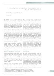
To derive reliable corrosion growth rates, a two tear process is suggested. At first, the<br />
reported anomalies from subsequent <strong>in</strong>spections are mapped aga<strong>in</strong>st each other.<br />
Secondly ,the normalized <strong>in</strong>spection signals are compared to compensate the<br />
systematic and random error from both runs. An example <strong>of</strong> such a comparison is<br />
given <strong>in</strong> figure 12. Data from three subsequent <strong>in</strong>spection surveys are shown. The<br />
signal pattern <strong>of</strong> a girth-weld can clearly be identified and is used for reference. The<br />
<strong>in</strong>dividual <strong>in</strong>spection report only gives the maximum depth <strong>of</strong> the corrosion area <strong>in</strong><br />
question. However, compar<strong>in</strong>g the raw ILI data clearly shows, that light corrosion is<br />
already present. This corrosion has not been reported, s<strong>in</strong>ce it was below the<br />
contractually agreed report<strong>in</strong>g threshold. Nevertheless, for the calculation <strong>of</strong> a<br />
corrosion growth rate and to better understand the mechanism <strong>of</strong> deterioration, the<br />
additional <strong>in</strong>formation drawn from the raw data is crucial.<br />
SUMMARY<br />
The current development <strong>of</strong> the carbon capture and storage (CCS) technologies is<br />
preceed<strong>in</strong>g the <strong>in</strong>spection <strong>of</strong> pipel<strong>in</strong>es transport<strong>in</strong>g CO 2. Because <strong>of</strong> its particular<br />
properties, the <strong>in</strong>spection <strong>of</strong> these pipel<strong>in</strong>es are lead<strong>in</strong>g to additional challenges for<br />
<strong>in</strong>spection companies.<br />
The critical properties <strong>of</strong> CO 2 transport<strong>in</strong>g pipel<strong>in</strong>es are the very dry conditions and<br />
the CO 2’s highly volatility as a solvent. The first is ma<strong>in</strong>ly abrasive to the driv<strong>in</strong>g and<br />
carry<strong>in</strong>g elements (PUR cups and disc) <strong>of</strong> an <strong>in</strong>spection tool, whilst the second has an<br />
Transportation <strong>of</strong> CO2 by Pipel<strong>in</strong>e page 6 <strong>of</strong> 12
Document Name <strong>ROSEN</strong> CO2 - F<strong>in</strong>al Paper 01_20110614<br />
Revision Date 21-Sep-11<br />
Empowered by Technology<br />
www.rosen<strong>in</strong>spection.net<br />
impact on the plastic parts, ma<strong>in</strong>ly after decompression at the end <strong>of</strong> a run.<br />
Consequently this can lead to damages on all parts such as sensors, cables, seals<br />
and connections. The effect <strong>of</strong> the CO 2 is enhanced when it is operated under<br />
supercritical conditions as some <strong>of</strong> the properties are gas-like even under very high<br />
pressure.<br />
Due to the experience with CO 2 and other critical media and pipel<strong>in</strong>e conditions,<br />
several solutions are presented to overcome the challenges. For example the wear on<br />
the <strong>ROSEN</strong> standard PUR was found not to be different to comparable pipel<strong>in</strong>es<br />
transport<strong>in</strong>g other media. Nevertheless, the different compositions <strong>of</strong> PUR clearly<br />
showed vary<strong>in</strong>g behavior after the run. The hard PUR composition for the guid<strong>in</strong>g<br />
discs and cups were nearly unaffected compared to other s<strong>of</strong>ter materials.<br />
Additionally, they showed they could cope with highly abrasive media <strong>in</strong> small<br />
diameter pipel<strong>in</strong>es .<br />
It also was shown, that the solvent effect <strong>of</strong> CO 2 has a more critical impact on the<br />
<strong>in</strong>spection tools. As the real effect occurs only dur<strong>in</strong>g and after decompression, the<br />
<strong>in</strong>spection itself is not affected. But the swell<strong>in</strong>g and bubbl<strong>in</strong>g <strong>of</strong> the different plastic<br />
materials can damage cables and sensors. Therefore, these parts have to be<br />
replaced after use with the accord<strong>in</strong>g consequences for <strong>in</strong>spection costs and efforts.<br />
But with <strong>in</strong>creas<strong>in</strong>g demand for these tools adapted design and material development<br />
are likely.<br />
The performance <strong>of</strong> the <strong>in</strong>spection technology is not affected by medium <strong>in</strong> this case.<br />
However, the special nature <strong>of</strong> CO 2 require a more thorough <strong>in</strong>spection and<br />
assessment program than other (hydrocarbon) pipel<strong>in</strong>es.<br />
REFERENCES<br />
WATT, JAMES: Carbon dioxide transport <strong>in</strong>frastructure: key learn<strong>in</strong>g and critical issues,<br />
<strong>in</strong>: Journal <strong>of</strong> Pipel<strong>in</strong>e Eng<strong>in</strong>eer<strong>in</strong>g, Vol. 9, No. 4, Dec. 2010<br />
COLINA, C.M. ET AL.: Thermal Properties <strong>of</strong> Supercritical Carbon Dioxide by Monte<br />
Carlo Simulations, Molecular Simulation, Vol.29 (6–7), June2003, pp.405–412.<br />
HUYSE, LUC ET AL.: Improvements <strong>in</strong> the accurate estimation <strong>of</strong> Top <strong>of</strong> the L<strong>in</strong>e<br />
Internal Corrosion <strong>of</strong> Subsea Pipel<strong>in</strong>es, Proceed<strong>in</strong>gs <strong>of</strong> the 8th International Pipel<strong>in</strong>e<br />
Conference IPC 2010 September 27 – October 1, 2010, Calgary, AB, Canada<br />
Transportation <strong>of</strong> CO2 by Pipel<strong>in</strong>e page 7 <strong>of</strong> 12
Document Name <strong>ROSEN</strong> CO2 - F<strong>in</strong>al Paper 01_20110614<br />
Revision Date 21-Sep-11<br />
FIGURES<br />
Empowered by Technology<br />
www.rosen<strong>in</strong>spection.net<br />
Figure 1: Polyurethane cup samples exposed to Ammonia over a period <strong>of</strong> 24h.<br />
a) Optimized composition b) Standard polyurethane<br />
Figure 2: Ammonia PUR on a 6” pull unit after 82 km and 60 hours exposition time.<br />
Figure 3: Geometry tool after 116 km <strong>in</strong> high pressure CO 2.<br />
Transportation <strong>of</strong> CO2 by Pipel<strong>in</strong>e page 8 <strong>of</strong> 12
Document Name <strong>ROSEN</strong> CO2 - F<strong>in</strong>al Paper 01_20110614<br />
Revision Date 21-Sep-11<br />
Empowered by Technology<br />
www.rosen<strong>in</strong>spection.net<br />
Figure 4: Front view on <strong>ROSEN</strong>’s Electronic Geometry tool, hours after the run with<br />
swollen buffer and bubbl<strong>in</strong>g pa<strong>in</strong>t<strong>in</strong>g.<br />
Figure 5: MFL tool after the run <strong>in</strong> 116 km high pressure CO 2.<br />
Transportation <strong>of</strong> CO2 by Pipel<strong>in</strong>e page 9 <strong>of</strong> 12
Document Name <strong>ROSEN</strong> CO2 - F<strong>in</strong>al Paper 01_20110614<br />
Revision Date 21-Sep-11<br />
Empowered by Technology<br />
www.rosen<strong>in</strong>spection.net<br />
Figure 6: Rear view <strong>of</strong> 24” MFL tool after the run with extremely swollen cables.<br />
Figure 7: Guid<strong>in</strong>g disc <strong>of</strong> 24” MFL <strong>in</strong> the workshop with visible bubbles.<br />
Figure 8: Pull unit for 8” l<strong>in</strong>e after 102 km <strong>in</strong> 60 bar ethylene.<br />
Transportation <strong>of</strong> CO2 by Pipel<strong>in</strong>e page 10 <strong>of</strong> 12
Document Name <strong>ROSEN</strong> CO2 - F<strong>in</strong>al Paper 01_20110614<br />
Revision Date 21-Sep-11<br />
Empowered by Technology<br />
www.rosen<strong>in</strong>spection.net<br />
Figure 9: Comb<strong>in</strong>ed <strong>in</strong>-l<strong>in</strong>e <strong>in</strong>spection with MFL technology (front), high-resolution<br />
geometry assessment (rear), and eddy current sensors for the detection and<br />
characterization <strong>of</strong> shallow <strong>in</strong>ternal corrosion (rear).<br />
Figure 10: High-resolution geometry sensor consist<strong>in</strong>g <strong>of</strong> a caliber sensor (β) and an<br />
eddy current sensor (δ) measur<strong>in</strong>g the lift-<strong>of</strong>f and <strong>in</strong>ternal corrosion.<br />
Figure 11: Comparison <strong>of</strong> the high-resolution mapp<strong>in</strong>g data for shallow <strong>in</strong>ternal<br />
corrosion, and the correspond<strong>in</strong>g photograph.<br />
Transportation <strong>of</strong> CO2 by Pipel<strong>in</strong>e page 11 <strong>of</strong> 12
Document Name <strong>ROSEN</strong> CO2 - F<strong>in</strong>al Paper 01_20110614<br />
Revision Date 21-Sep-11<br />
Empowered by Technology<br />
www.rosen<strong>in</strong>spection.net<br />
Figure 12: Example <strong>of</strong> corrosion growth monitor<strong>in</strong>g based on an MFL signal data. The<br />
<strong>in</strong>dividual <strong>in</strong>spection report depicts the maximum depth for general corrosion only.<br />
However a comparison <strong>of</strong> the normalized raw data <strong>in</strong>dicates sub-threshold corrosion<br />
growth <strong>in</strong> the surround<strong>in</strong>g area <strong>of</strong> the reported anomaly.<br />
Transportation <strong>of</strong> CO2 by Pipel<strong>in</strong>e page 12 <strong>of</strong> 12