High-quality Smart-pig Inspection of Dents - ROSEN Inspection ...
High-quality Smart-pig Inspection of Dents - ROSEN Inspection ...
High-quality Smart-pig Inspection of Dents - ROSEN Inspection ...

You also want an ePaper? Increase the reach of your titles
YUMPU automatically turns print PDFs into web optimized ePapers that Google loves.
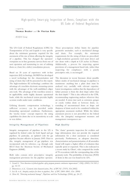
<strong>High</strong>-<strong>quality</strong> <strong>Smart</strong>-<strong>pig</strong> <strong>Inspection</strong> <strong>of</strong> <strong>Dents</strong>, Compliant with the<br />
US Code <strong>of</strong> Federal Regulations<br />
a report by<br />
Thomas Beuker and Dr Florian Rahe<br />
<strong>ROSEN</strong> Group<br />
The US Code <strong>of</strong> Federal Regulations (CFR) for<br />
Transportation <strong>of</strong> Gas and Liquids is very specific<br />
about the minimum geometry required for the<br />
assessment <strong>of</strong> the size <strong>of</strong> dents affecting the integrity<br />
<strong>of</strong> a pipeline. This has changed the operators’<br />
viewpoint on in-line geometry surveys from one <strong>of</strong><br />
asset operation and monitoring to one <strong>of</strong> utilising<br />
them as a basis for a defect remediation process.<br />
Based on 20 years <strong>of</strong> experience with in-line<br />
inspection (ILI) technology, <strong>ROSEN</strong> has developed<br />
a novel technology for the characterisation and<br />
sizing <strong>of</strong> dents that will be presented in this report.<br />
The high-resolution ILI technology combines the<br />
advantage <strong>of</strong> a touchless electronic measuring system<br />
with the advantages <strong>of</strong> the well-established caliper<br />
arm tools. The advantage <strong>of</strong> the touchless system is<br />
its applicability under highly dynamic operational<br />
loads, while the mechanical system provides highly<br />
accurate results under static conditions.<br />
Utilising dynamic compensation technology, a<br />
sufficient accuracy can be provided under<br />
demanding operational conditions. Furthermore,<br />
the ‘mecha tronic’ concept improves the sizing<br />
capabilities for dents due to its insensitivity to scale<br />
or wax debris.<br />
Integrity Management <strong>of</strong> Pipelines<br />
Integrity management <strong>of</strong> pipelines in the US is<br />
regulated by federal codes for both liquid and gas<br />
pipelines. In particular, an updated code for gas<br />
pipelines became effective in January 2005. Prior to<br />
this, integrity management <strong>of</strong> gas pipelines was<br />
incorporated only by reference, e.g. through code<br />
B31.8 from the American Society <strong>of</strong> Mechanical<br />
Engineers (ASME).<br />
Both rules contain strict prescriptive integrity<br />
management provisions for the pipeline operator.<br />
BUSINESS BRIEFING: OIL & GAS PROCESSING REVIEW 2005<br />
These prescriptions define limits for pipeline<br />
geometric anomalies, such as mechanical damage<br />
and dents. For example, the minimum<br />
requirements for the sizing <strong>of</strong> dents are prescribed:<br />
a high-resolution geometry tool must detect and<br />
size dents with a depth ≥ 0.25 inches (6.35mm).<br />
Additionally, a process for inspecting against<br />
provisions <strong>of</strong> a management based rule, rather than<br />
inspecting for compliance with a purely<br />
prescriptive rule, is encouraged 1 .<br />
The discussion in recent literature about possible<br />
failure modes <strong>of</strong> mechanical damage in pipelines is<br />
unanimous: anything but a plain dent must be<br />
analysed very carefully with relevant expertise.<br />
Latest investigations confirm that the dependency <strong>of</strong><br />
failure pressure is from the dent shape rather than<br />
the dent depth. 2,3 This is also reflected in the CFR,<br />
recommending engineering analyses wherever they<br />
are needed. A stress riser such as corrosion, gouges<br />
or cracks within dents or between dents, rerounding<br />
<strong>of</strong> unconstrained dents or shape and<br />
sharpness <strong>of</strong> dents need to be considered within the<br />
appropriate assessment method. While the failure<br />
assessment process is not prescribed in the federal<br />
rules, the (integrity) management measures and<br />
management consequences are.<br />
<strong>High</strong> Quality<br />
Technology & Services Section<br />
The ‘classic’ geometry inspection for ovalities and<br />
large deformations does not provide the required<br />
information for a dent assessment as considered<br />
previously. Furthermore, an adequate detection,<br />
characterisation and parameterisation <strong>of</strong> all anomalies<br />
found will require a higher effort <strong>of</strong> evaluation than<br />
typically spent or requested. This is also indicated in<br />
a recent study by Olson 4 , who compared the results<br />
<strong>of</strong> 78 excavations with the corresponding data <strong>of</strong> the<br />
geometry tools. The probability <strong>of</strong> detection (POD)<br />
<strong>of</strong> dents in this case was found to be 32%.<br />
1. Gerard S, “New directions in federal pipeline safety program promote continuous improvement”, OGJ, (2005); Vol 103.2:<br />
pp. 52–55.<br />
2. Dinnovitzer, et al., Geometric dent characterization, Proc. <strong>of</strong> IPC’02 -27076, (Oct.2002).<br />
3. Leis B, et al., Integrity analysis for dents in pipelines, Proc. <strong>of</strong> IPC 2004 -0061, (Oct. 2004).<br />
4. Olson M, “Detecting mechanical damage”, PipeLine and Gas Technology (2004); pp. 26–27.<br />
1
2<br />
Technology & Services Section<br />
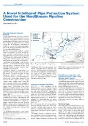
Figure 1: <strong>High</strong>-<strong>quality</strong> Geometry Unit (XGP) in Combination with Different<br />
<strong>High</strong>-resolution Metal Loss <strong>Inspection</strong> and Crack <strong>Inspection</strong> Tools<br />
From left to right: ECD+XGP, AFD+XGP, CDP+XGP and XGP.<br />
Introducing a high-<strong>quality</strong> in-line inspection process<br />
for dents and mechanical damage can provide the<br />
basis information, such as the geometric data <strong>of</strong> dents<br />
and stress risers, to start a managed integrity process<br />
for the inspected line. The more high-resolution and<br />
high-<strong>quality</strong> information that is available about the<br />
anomaly found, the better the subsequent failure<br />
analyses can be.<br />
It is important not only to size and describe the<br />
dents with high accuracy, but also to detect and<br />
characterise the mentioned stress risers. State-<strong>of</strong>-theart<br />
equipment for characterisation <strong>of</strong> the stress riser<br />
are high-resolution ILI tools based on the magnetic<br />
flux leakage principle (MFL), circumferential MFL<br />
tools or the recently developed Electro Magnetic<br />
Acoustic Transducer (EMAT) Crack Detection<br />
(ECD) tool based on electromagnetic coupled<br />
ultrasound. In addition, or more preferable in<br />
combination with one <strong>of</strong> those tools, a highresolution<br />
Geometry Pig (XGP) rendering the pipe<br />
shell in space must be used (see Figure 1).<br />
Circumferential Resolution and<br />
Coverage<br />
The performance <strong>of</strong> a geometry inspection<br />
configuration for dents can be estimated using an<br />
analytical model. According to the model the<br />
sizing accuracy and the POD for dents can be<br />
determined as a function <strong>of</strong> the circumferential<br />
resolution and the coverage <strong>of</strong> the sensing area <strong>of</strong><br />
the caliper sensors.<br />
The decisive parameter for the POD is mainly the<br />
coverage <strong>of</strong> the caliper sensor in circumferential<br />
direction. A geometry tool like the established<br />
<strong>ROSEN</strong> Electronic Geometry Pig (EGP) with a<br />
circumferential coverage <strong>of</strong> 100% would perform<br />
with an analytical POD <strong>of</strong> one for the three types <strong>of</strong><br />
dents. The 100% coverage is achieved with the<br />
touchless operating sensor unit. Another example is<br />
the simple caliper tool, equipped with 12 caliper<br />
arms and a typical coverage <strong>of</strong> 55%. The POD in this<br />
case is reduced to 0.75 for a sharp dent <strong>of</strong> 0.32 inches<br />
(8.1mm) depth (2% improved detection). Again, this<br />
indicates the importance <strong>of</strong> coverage.<br />
Another effect that can be studied is the systematical<br />
undersizing <strong>of</strong> dents as a function <strong>of</strong> circumferential<br />
resolution and coverage. Assuming that a dent is not<br />
hit at the tip by a caliper or scanning sensor, the<br />
maximum possible undersizing <strong>of</strong> the dent depth can<br />
be calculated for a geometry inspection configuration.<br />
The maximum possible undersizing <strong>of</strong> the dent, in<br />
comparison with the real depth, is plotted versus the<br />
circumferential coverage for a different number <strong>of</strong><br />
caliper arms. It can be seen that an increase <strong>of</strong> caliper<br />
arms improves the sizing difference. Nevertheless,<br />
coverage close to 100% is the strongest parameter to<br />
achieve an accurate depth measurement.<br />
The maximum coverage a geometry inspection tool<br />
with a single plane <strong>of</strong> caliper sensors will achieve is<br />
close to the bore reduction a tool can negotiate,<br />
typically reduced by approximately 15% (due to<br />
required mechanical tolerances). Therefore, a<br />
typical value <strong>of</strong> 75% passage leads to a maximum<br />
coverage <strong>of</strong> 60%.<br />
The circumferential resolution determines the<br />
parameterisation capabilities for geometric<br />
anomalies. Recent studies did show that a ‘dent<br />
acuity’ <strong>of</strong> 0.1d/w must be resolved (acuity=2d/w,<br />
where d=dent depth and w=dent width) 1 .<br />
Including the previously mentioned depth<br />
threshold <strong>of</strong> 0.25 inches (6.35mm), a dent <strong>of</strong> 5<br />
inches (127mm) wide has to be resolved.<br />
Based on these theoretical considerations, a geometry<br />
inspection configuration is desired with an acceptable<br />
total circumferential resolution e.g. < 2 inches<br />
(50.8mm) and caliper sensors arranged in two axially<br />
separated planes governing a possible circumferential<br />
coverage <strong>of</strong> more than 95%.<br />
Mechatronic Principle<br />
Other issues, beside the requirements derived from<br />
the preceding analytical considerations and the<br />
regulatory demands highlighted, have to be<br />
considered for the conceptual design <strong>of</strong> a geometry<br />
inspection tool.<br />
A disadvantage <strong>of</strong> the traditional mechanical caliper<br />
tool design, where the mechanical movement <strong>of</strong> the<br />
caliper is transformed into a position signal, is the<br />
dynamic behaviour <strong>of</strong> the arms under ‘run’<br />
conditions. This typically leads to inspection speed<br />
BUSINESS BRIEFING: OIL & GAS PROCESSING REVIEW 2005
estrictions. Above a critical tool speed, the caliper<br />
arm starts to lose continuous contact with the<br />
internal surface <strong>of</strong> the pipeline. However, at low<br />
speeds, abrupt changes at the internal pipe surface<br />
may not be monitored correctly. Pure mechanical<br />
designs that try to overcome these problems have to<br />
be lightweight and, hence, are quite fragile.<br />
Therefore, these systems do not extend the<br />
operational range <strong>of</strong> this inspection task.<br />
A solution for this problem is provided by touchless<br />
measurement technology. To achieve a high<br />
measurement accuracy and a satisfying circumferential<br />
resolution, a mechanic caliper arm system<br />
equipped with a sensor to transform the mechanical<br />
movement into an electric signal and an electronic<br />
distance measurement were combined to create a<br />
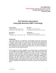
mechatronic solution (see Figure 2). The picture<br />
shows the concept <strong>of</strong> having a touchless electronic<br />
sensor integrated inside the sensor head and a<br />
position sensor attached at the bottom monitoring<br />
the mechanical position <strong>of</strong> the sensor arm. The<br />
touchless electronic sensor is used to compensate for<br />
data obtained from the dynamic behaviour <strong>of</strong> the<br />
caliper arm. The unwanted inertia <strong>of</strong> the caliper arm<br />
is fully assimilated by the touchless measurement.<br />
Sharp transitions at the internal surface, such as a<br />
pipe misalignment at a girth weld, are monitored<br />
well. Since the electronic sensor is insensitive to<br />
non-conductive material, the compensation method<br />
refers always to the metal internal surface <strong>of</strong> the<br />
pipeline. Scale or wax debris, although detected by<br />
the system, will not affect the geometry evaluation<br />
<strong>of</strong> the pipeline. A single mechatronic unit is<br />
designed to cope with a tool-speed <strong>of</strong> up to<br />
11.2mph (5m/s) and to provide an accuracy <strong>of</strong> 0.02<br />
inches (0.5mm) for radial measurements.<br />
Tool Design<br />
Due to the linear equation connecting the pipeline<br />
diameter with its circumferential perimeter, the<br />
coverage <strong>of</strong> a single unit tool is linked to the internal<br />
diameter (ID)-passage <strong>of</strong> the unit. As a rule <strong>of</strong> thumb,<br />
the coverage for a single plane geometry tool equals<br />
the specified passage minus 15%. Thus a typical<br />
caliper tool with a passage <strong>of</strong> 75% would cover only<br />
60% <strong>of</strong> the internal pipe surface.<br />
Therefore, an accurate sizing <strong>of</strong> dents or other<br />
geometric properties in a pipeline requires 100%<br />
coverage in circumference by the geometry sensors.<br />
To achieve this, the inspection solution must consist<br />
<strong>of</strong> two inspection planes, where the trailing sensor<br />
covers the gap <strong>of</strong> the preceding unit. The tool<br />
concept for the <strong>ROSEN</strong> high-resolution XGP<br />
consists <strong>of</strong> two sensor units connected to each other<br />
and as a result guarantees 100% coverage <strong>of</strong> the<br />
internal surface.<br />
<strong>High</strong>-Quality <strong>Smart</strong>-Pig <strong>Inspection</strong> <strong>of</strong> <strong>Dents</strong>, Compliant with US CFR<br />
BUSINESS BRIEFING: OIL & GAS PROCESSING REVIEW 2005<br />
Figure 2: XGP Mechatronic Caliper Sensor<br />
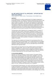
Figure 3: XGP Tool and Data Sample Obtained on<br />
Test Joints Containing a Dent and a Wrinkle Bend<br />
To allow a detailed evaluation and characterisation <strong>of</strong><br />
the geometric anomalies the circumferential<br />
resolution was set to < 1.2 inches (30mm). This<br />
exceeds the requirements for the lateral<br />
characterisation <strong>of</strong> a dent as typically required.<br />
Furthermore, caliper arms providing the discussed<br />
accuracy are fragile. In turn, the presented<br />
mechatronic concept, which compensates for the<br />
inertia <strong>of</strong> the mechanical caliper arm, allows a more<br />
robust design <strong>of</strong> the caliper arm improving the<br />
survey conditions under which the inspection<br />
system can be operated. The XGP is equipped with<br />
these ‘heavy duty’ caliper arms (see Figure 3).<br />
The XGP unit is also equipped with a Gyro system<br />
measuring three dimensional (3-D) co-ordinate<br />
system (XYZ) that maps an accurate route <strong>of</strong> the<br />
pipeline and can help to determine bend radii, bend<br />
length and bend direction. The XYZ information is<br />
the basis for a stress/strain analysis on a larger scale,<br />
which in turn can be part <strong>of</strong> the remaining lifeassessment<br />
procedure carried out for local anomalies.<br />
Geometry inspection is advancing into the high-<br />
3
4<br />
Technology & Services Section<br />
resolution technologies. The assessment <strong>of</strong> a dent<br />
requires all available information characterising<br />
potential stress risers in the vicinity <strong>of</strong> the dent.<br />
Therefore it can be useful, from an operational point<strong>of</strong>-view,<br />
to combine the XGP unit to another<br />
inspection technology (such as a corrosion survey)<br />
that provides this information (see Figure 1).<br />
Conclusion<br />
The demand for reliable dent detection and sizing<br />
has changed the scope <strong>of</strong> existing geometry<br />
inspection services with regards to the inspection<br />
technology used, as well as the evaluation process<br />
<strong>of</strong> the data. Geometry inspection has entered the<br />
‘high-<strong>quality</strong>’ inspection market. Analytical<br />
considerations emphasise the importance <strong>of</strong> both<br />
coverage and resolution in the circumferential<br />
direction <strong>of</strong> the pipe perimeter. Measurement <strong>of</strong><br />
the mechanical position <strong>of</strong> the caliper arm in<br />
combination with a touchless distance<br />
measurement provides better accuracy independent<br />
from the caliper’s inertia and a wider operational<br />
range <strong>of</strong> the system. ■<br />
BUSINESS BRIEFING: OIL & GAS PROCESSING REVIEW 2005