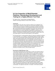
DEEPWATER, HIGH-PRESSURE AND MULTIDIAMETER PIPELINES
DEEPWATER, HIGH-PRESSURE AND MULTIDIAMETER PIPELINES
DEEPWATER, HIGH-PRESSURE AND MULTIDIAMETER PIPELINES

You also want an ePaper? Increase the reach of your titles
YUMPU automatically turns print PDFs into web optimized ePapers that Google loves.
<strong>DEEPWATER</strong>, <strong>HIGH</strong>-<strong>PRESSURE</strong> <strong>AND</strong> <strong>MULTIDIAMETER</strong> <strong>PIPELINES</strong><br />
A CHALLENGING IN-LINE INSPECTION PROJECT<br />
Dr. Hubert Lindner, ROSEN Technology & Research Center, Lingen, Germany<br />
INTRODUCTION<br />
In-line corrosion inspections with Magnetic Flux Leakage (MFL) or ultrasonic technology (UT)<br />
have become standard in pipeline integrity assessment worldwide. Lately, ultra-high<br />
resolution geometry inspection based on eddy current methods (EC) has been established to<br />
assess more accurately the internal geometry of pipelines.<br />
Approximately 60 % of the world’s gas, oil and product pipelines can be inspected with offthe-shelf<br />
inspection tools. In the past the remaining 40 % of pipelines have often been<br />
classified as ‘unpiggable’. A large proportion of these unpiggable pipelines are offshore,<br />
multi-diameter lines, with low flow conditions and often with very challenging OD ratios.<br />
Today, it is possible to develop individualized inspection solutions for multi-diameter pipeline<br />
systems. The development of such solutions can already be incorporated into the FEED<br />
process for these offshore structures. On the other hand, a great number of pipelines were<br />
constructed and laid in times when in-line inspection (ILI) was not available or not a<br />
requirement. Occasionally the passage of these offshore pipelines is restricted.<br />
This paper presents the development of a series of 14"/18" ILI tools and their successful<br />
application survey in a 95 km long, high-pressure, heavy-wall, low-flow off-shore pipeline. In<br />
a team-effort between the pipeline operator (“Operator”) and the inspection company<br />
(ROSEN) a solution was developed for a challenging pipeline, which would have been<br />
considered ‘unpiggable’ in the recent past.<br />
THE PROJECT REQUIREMENTS<br />
The project began with a request of the Operator to inspect a particular 14"/18" offshore<br />
pipeline to evaluate the integrity of the pipeline via an internal inspection.<br />
In addition to its multi-diameter design, the pipeline posed several further challenges. The<br />
essential properties are as follows:<br />
- Length: 163.9 km<br />
- 14": 11.9 km (wall thickness: 20.6 mm – 22.2 mm)<br />
- 18": 151.9 km (wall thickness: 22.2 mm – 28.6 mm)<br />
- Bends 14": 5D<br />
- Bends 18": 5D<br />
- Maximum water depth: 1900 m<br />
- Maximum pressure: 290 bar<br />
- Known Minimum ID known: 300 mm<br />
- Internally coated<br />
- Medium: gas<br />
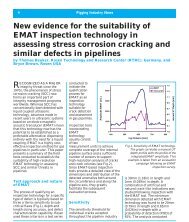
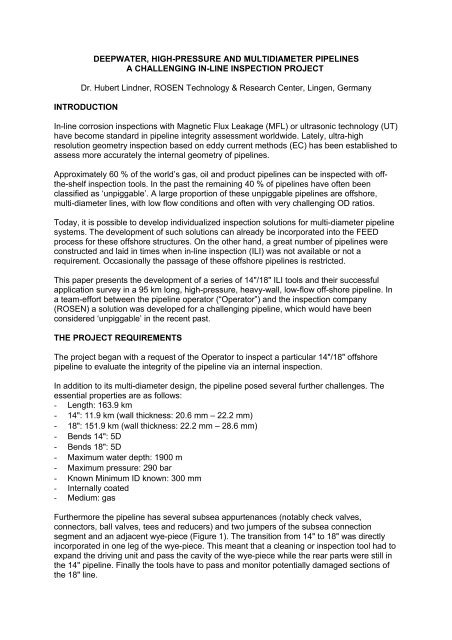
Furthermore the pipeline has several subsea appurtenances (notably check valves,<br />
connectors, ball valves, tees and reducers) and two jumpers of the subsea connection<br />
segment and an adjacent wye-piece (Figure 1). The transition from 14" to 18" was directly<br />
incorporated in one leg of the wye-piece. This meant that a cleaning or inspection tool had to<br />
expand the driving unit and pass the cavity of the wye-piece while the rear parts were still in<br />
the 14" pipeline. Finally the tools have to pass and monitor potentially damaged sections of<br />
the 18" line.
Figure 1: General view sketch of the 14"/18" pipeline<br />
PROJECT PLANNING<br />
The Operator’s goal during project planning was to maintain its customers’ product flow while<br />
ensuring the integrity and safety of its pipeline operations. With those aims in mind, the<br />
project team sought to inspect the pipeline during regular operation (no water filling or bidirectional<br />
inspection from the receiver side) through a program of high-resolution geometry<br />
(called RoGeo Xt) and MFL (CDP). Since the consequences of a possible failure of the<br />
pigging operation could have been enormous and because the particular challenges of the<br />
pipeline and operation, an extensive test program was incorporated.<br />
The project plan had included following fields:<br />
Tool Development<br />
ROSEN had to develop, design and manufacture three multi diameter-tools (gauging,<br />
extended geometry, MFL) adapted to the pipeline and operational requirements.<br />
Testing<br />
An extensive test program was developed which included pull and pump tests of components<br />
and parts in the existing test facilities. This included pull tests through the existing 14"/16"<br />
and 18" test lines as well as pump tests in the 16" single size pump test loop simulating<br />
heavy external pipe damage.<br />
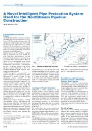
For a full size test of the tools, the project included a test loop containing all crucial elements<br />
and features of the original pipeline (Figure 2) whereby all simulations of installations would<br />
be delivered by the Operator and the pipes, bends and additional elements would be<br />
supplied by ROSEN. The test loop was assembled and operated on the area of the<br />
Research & Technology Center (RTRC) in Lingen, Germany.
Figure 2: Final drawing of the test loop<br />
Simulation of pipeline flow conditions<br />
As the run conditions are very important for a reliable inspection run, the Operator provided<br />
data to simulate actual pipeline flow calculations. The combination of the planned flow<br />
conditions together with the effect of the pipeline topography and temperature turned to be<br />
out a critical issue with remarkable impact on the project schedule.<br />
Preparation of On-Site Activities<br />
During the preparation period the aspects of on-site activities were also widely considered.<br />
Based on the launcher and receiver documentation as well as on-site visit information, the<br />
launching (vertical) and receiving procedures were defined by ROSEN USA. The necessary<br />
equipment (transport frame, launching tube) was then designed and manufactured. All these<br />
procedures, parts and actions were finalized in an on-site tool handling and<br />
launching/receiving procedure document.<br />
Further the project addressed a contingency plan for the unwanted case that a tool exceeded<br />
the calculated traveling time or became stationary.<br />
Preparation of Data Evaluation<br />
The fact that the investigation’s goal was to discover the unknown condition of the pipeline<br />
required a coordinated and quick evaluation of the inspection data as well as other possible<br />
indications (gauge plate, tool condition), before progression to the next phase. Therefore the<br />
ROSEN on-site personnel were chosen to be experienced in both tool behavior and data<br />
evaluation. For a detailed analysis of the inspection data, capacity at ROSEN USA and the<br />
RTRC in Lingen was scheduled.<br />
Project Communication<br />
For the entire duration of the project a policy of very close communication between the<br />
Operator and ROSEN (RTRC and Houston branch) was realized. This included several<br />
meetings and occasionally weekly telephone conferences. This policy allowed close cooperation<br />
and well-coordinated procedures throughout.
TOOL DESIGN<br />
The main challenges for the tool designs was the wide multi-diameter working range from<br />
about 300 mm to 415 mm, the high pressure (295 bar) and the wye-piece passage. The<br />
direct consequences were small tool bodies and long sealing lengths. Since it was known<br />
that the pipeline was internally coated and that other cleaning tools had already passed the<br />
pipeline without heavy wear, it was decided to use conservative design for the gauging tool.<br />
However, it became clear after the first pump test in the 14"/18" test loop that the setup had<br />
to be adjusted. The tool consisted of two bodies connected by a flexible joint. A four guiding<br />
petal disc design was chosen (Figure 3). The tool was also equipped with a Pipeline Data<br />
Logger (PDL) and a transmitter.<br />
Figure 3: 14"/18" Gauging tool<br />
Figure 3 shows the sealing length to accommodate the wye-piece passage (1.4 m), which<br />
had to be the same for the intelligent tools. For those latter tools (essentially for the MFL tool)<br />
however, the pull unit had to provide much more stability and driving force than the petal<br />
setup could provide. Therefore a particular segmented multi-diameter driving unit had to be<br />
developed. Although it was designed for the MFL unit, it could also be used for the geometry<br />
tool (Figure 4). The staggered sensor arrays of this tool provided full circumferential<br />
coverage in pipelines of both sizes (i.e. 14"/18").<br />
Figure 4: The 14"/18" Extended Geometry tool (RoGeo Xt)
In the case of the MFL tool, the driving unit has to pull two heavy-wall (25 mm), multidiameter<br />
MFL units and a trailer for batteries and electronics (Figure 5). All components of<br />
these three tools were designed to withstand a pressure of 300 bar.<br />
Figure 5: The 14"/18" Metal Loss tool (CDP)<br />
TESTING<br />
This phase was divided into three parts:<br />
a. Pressure test of standard components and vessels (300 bar)<br />
b. Tool component tests (pulling force, flip over test)<br />
c. Test for the complete tools<br />
Out of these, the tests for the complete tools were by far the most laborious. All tools were<br />
pulled through the 14", 16" and 18" pull test lines. During these runs, the intelligent tools<br />
already collected information and the pulling forces were recorded.<br />
Figure 6: The 14"/18" test loop<br />
The most important tests were, of course, the pump tests in the special 14"/18" test loop<br />
(Figure 6). During these runs both tool and pipeline flow and pressure data were measured<br />
to evaluate tool performance and optimize the behavior.<br />
The test loop was put into operation at the end of October 2007. In the time until the tools<br />
were delivered in February 2008, the following runs were conducted:<br />
Gauging tool: 4 runs (one change in discs setup)
RoGeo Xt tool: 6 runs (one change I to the design of the driving unit due to damage)<br />
CDP tool: 12 runs (one change to the design of the driving unit for enhanced function)<br />
Differential pressure and flow measurements were taken. The flow speed was the only<br />
operational parameter which could be varied during the tests. Due to the fact, that the real<br />
pipeline is operated with gas and the pump test loop with water, some runs were conducted<br />
at a very low flow speed (0.25 m/s) to approximate as closely as possible the effect of<br />
bypass in a gas line.<br />
During the test phase all tools passed the entire flow loop at all times. Occasionally high<br />
differential pressure values were observed and analyzed and important findings were gained.<br />
These were for example an improved performance of the disc setup of the CLP, and<br />
modifications of the driving unit.<br />
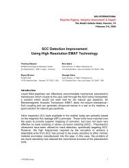
Figure 7: Results of pump test with RoGeo Xt (Top: dp, Bottom: tool inclination)<br />
Figure 7 illustrates the differential pressure (dp) along the RoGeo Xt tool as measured by an<br />
on-board PDL during a pump test. The dp is about 2 bar in the 14" and 1 bar in the 18"<br />
section. The bottom diagram shows the inclination of the tool during the run. The inclination<br />
is a good indicator for the tool position resulting from the two jumpers as shown very clearly<br />
in Figure 7. The swan necks of launcher and receiver too are plainly visible. The pressure<br />
diagram also shows a distinct peak of nearly 10 bar. This peak reflects damage to the pull<br />
unit including missing wheel support. In combination with the synchronized display of the<br />
inclination it was possible to identify the reason for the peak and corrective design actions<br />
could be made. The subsequent tests did not show any similar effect.
Figure 8: Data of selected features collected by the RoGeo Xt tool (raw data, not to be<br />
scaled)<br />
Some of the measured pipeline installations are represented in Figure 8. The raw data<br />
furnished by the caliper arms clearly indicate the valves, connectors, tees and of course the<br />
wye-piece.<br />
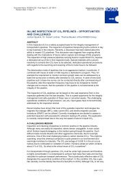
PDL measurements of a MFL test run can be seen in Figure 9. Again the lower diagram<br />
shows the tool inclination in support of the information provided by the upper graph. The MFL<br />
tool needs a higher dp than expected: it is between 3.8 bar in an 18" and 5.5 bar in a 14"<br />
straight pipeline segment. For the passage of the jumper bend combination, a slightly greater<br />
differential pressure is required (up to 7.5 bar). The passage of the wye-piece was performed<br />
without stop and shows only little effect on the measurement.
Figure 9: Results of the pump test with the CDP tool (top: differential pressure, bottom: tool<br />
inclination)<br />
Finally, a full-scale replica of the vertical launcher was built and the launching procedure<br />
performed as documented.<br />
After all these tests, calculations and planning, the tools and procedures were ready for the<br />
job and mobilized. Meanwhile the operational data (90 bar, 65.000 sm^3/h) provided good<br />
conditions for the run. As the actual pipeline was internally coated and had certain contend of<br />
fluids, a lower dp was expected compared to the pump test in the non-coated test loop.<br />
GAUGING <strong>AND</strong> INSPECTION RUNS<br />
For the preparation of the actual pigging project, a lot of supporting actions had to be<br />
prepared and conducted. For example a special vessel with a remotely operated vehicle<br />
(ROV) was hired for subsea operations, subsea markers were placed and the required<br />
equipment was supplied to the platform.<br />
Actual pigging operations started at the end of June 2008 with the gauging tool. This initial<br />
run was successful: neither the tool nor the gauge plate showed damage, and wear on the<br />
PUR was low. Therefore the decision was made to run the geometry tool.
Figure 10: Vertical launching of the geometry and MFL tool<br />
The geometry tool (Figure 10: left) was launched without any problem and arrived within the<br />
calculated time. The data collected during the geometry run was complete and of very high<br />
quality. The same evening initial data analysis was performed by the on-site team and data<br />
was transferred to the ROSEN Data Evaluation Department. One extreme measurement was<br />
observed and isolated for detailed evaluation. Because of the known pipeline layout, it was<br />
clear that the signal was recorded in the check valve between the jumpers. The evaluation of<br />
the data revealed the internal geometry of the check valve (Figure 12). In the RTRC, this<br />
information was carefully compared to the tool design and decided that it is just as expected<br />
and therefore no critical installation, though the MFL tool could be launched.<br />
Because of the length of the launcher barrel, the two segments of the driving unit had to be<br />
pushed into the reduction for a certain distance. Additionally, a launching tube was used to<br />
keep the magnet units away from the wall to reduce the required pushing forces. As this was<br />
also tested on a dummy launcher with original measures, the launching procedure worked<br />
perfectly. Again, the tool was received within the allocated time and with complete data of<br />
high quality.<br />
Figure 11: The tool in the receiver Figure 12: Evaluation of geometry tool:<br />
Check Valve<br />
SUMMARY<br />
The Operator desired to perform an in-line inspection to gather data to determine pipeline<br />
integrity. Because of the particular properties of the pipeline (high pressure, multi-diameter<br />
14"/18", high wall thicknesses and subsea installations) and the high risk of the deep water<br />
operation, a unique development project was necessary. Therefore ROSEN developed and<br />
produced two in-line inspection tools (geometry and MFL). In close co-operation with the<br />
Operator, a large test program was performed at the ROSEN facility in Lingen ending with<br />
full scale tests in a 130 m test loop including all crucial installation simulations.
During the test phase some deciding improvements of the design were identified and made<br />
due to pump test results. All tests, results and changes were communicated among the<br />
project team, leading to a demonstrated solution and confidence for the inspection project.<br />
Parallel to the tool development, manufacturing and testing, the Operator and ROSEN<br />
evaluated the operational conditions and the on-site procedures. Furthermore, a contingency<br />
plan was compiled regarding the definition of possible incidences and the following actions.<br />
Due to the detailed and comprehensive preparation of the inspection and the professional<br />
and uncomplicated cooperation of the project teams all tool runs (gauging, geometry and<br />
MFL) were launched and received without incident. The tools arrived in time with complete<br />
data of high quality.