DEEPWATER, HIGH-PRESSURE AND MULTIDIAMETER PIPELINES
DEEPWATER, HIGH-PRESSURE AND MULTIDIAMETER PIPELINES
DEEPWATER, HIGH-PRESSURE AND MULTIDIAMETER PIPELINES

Create successful ePaper yourself
Turn your PDF publications into a flip-book with our unique Google optimized e-Paper software.
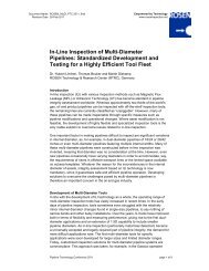
TOOL DESIGN<br />
The main challenges for the tool designs was the wide multi-diameter working range from<br />
about 300 mm to 415 mm, the high pressure (295 bar) and the wye-piece passage. The<br />
direct consequences were small tool bodies and long sealing lengths. Since it was known<br />
that the pipeline was internally coated and that other cleaning tools had already passed the<br />
pipeline without heavy wear, it was decided to use conservative design for the gauging tool.<br />
However, it became clear after the first pump test in the 14"/18" test loop that the setup had<br />
to be adjusted. The tool consisted of two bodies connected by a flexible joint. A four guiding<br />
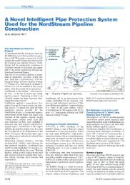
petal disc design was chosen (Figure 3). The tool was also equipped with a Pipeline Data<br />
Logger (PDL) and a transmitter.<br />
Figure 3: 14"/18" Gauging tool<br />
Figure 3 shows the sealing length to accommodate the wye-piece passage (1.4 m), which<br />
had to be the same for the intelligent tools. For those latter tools (essentially for the MFL tool)<br />
however, the pull unit had to provide much more stability and driving force than the petal<br />
setup could provide. Therefore a particular segmented multi-diameter driving unit had to be<br />
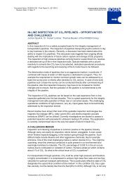
developed. Although it was designed for the MFL unit, it could also be used for the geometry<br />
tool (Figure 4). The staggered sensor arrays of this tool provided full circumferential<br />
coverage in pipelines of both sizes (i.e. 14"/18").<br />
Figure 4: The 14"/18" Extended Geometry tool (RoGeo Xt)