Experimental investigation of jet mixing of a co-flow jet airfoil
Experimental investigation of jet mixing of a co-flow jet airfoil
Experimental investigation of jet mixing of a co-flow jet airfoil

You also want an ePaper? Increase the reach of your titles
YUMPU automatically turns print PDFs into web optimized ePapers that Google loves.
5th Flow Control Conference28 June - 1 July 2010, Chicago, IllinoisAIAA 2010-4421<strong>Experimental</strong> Investigation <strong>of</strong>Jet Mixing <strong>of</strong> a Co-Flow Jet AirfoilB. P. E. Dano, D. Kirk and G.-C. ZhaDept. <strong>of</strong> Mechanical and Aerospace EngineeringUniversity <strong>of</strong> Miami, Coral Gables, FL 33124AbstractDownloaded by Gecheng Zha on January 16, 2013 | http://arc.aiaa.org | DOI: 10.2514/6.2010-4421The <strong>jet</strong> <strong>mixing</strong> <strong>of</strong> a <strong>co</strong>-<strong>flow</strong> <strong>jet</strong> (CFJ) <strong>airfoil</strong> is investigated to understandthe mechanism <strong>of</strong> lift enhancement, drag reduction, and stall margin increase.Digital Particle Image Velocimetry, <strong>flow</strong> visualization and aerodynamic forcesmeasurements are used to reveal the insight <strong>of</strong> the CFJ <strong>airfoil</strong> <strong>mixing</strong> process.At low AoA and low momentum <strong>co</strong>efficient, the <strong>mixing</strong> between the wall <strong>jet</strong> andmain<strong>flow</strong> is dominant with large structure <strong>co</strong>herent structures for the attached <strong>flow</strong>s.When the momentum <strong>co</strong>efficient is increased, the large vortex structure disappears.At high AoA with <strong>flow</strong> separation, the CFJ creates a upstream <strong>flow</strong> strip betweentwo <strong>co</strong>unter rotating vertical shear layer, i.e., the outer shear layer and inner <strong>flow</strong>induced by CFJ. The UFS is characterized with large vortex free region. The <strong>co</strong>-<strong>flow</strong> wall<strong>jet</strong> is deflected normal to the <strong>airfoil</strong> surface characterized with a saddle point. Withincreased momentum <strong>co</strong>efficient <strong>of</strong> the CFJ, the saddle point moves downstream andeventually disappears when the <strong>flow</strong> is attached.Turbulence plays a key role in <strong>mixing</strong> the CFJ with main<strong>flow</strong> to transport highkinetic energy from the <strong>jet</strong> to main<strong>flow</strong> so that the main<strong>flow</strong> can remain attached at highAoA to generate high lift. When the <strong>flow</strong> is separated, increased CFJ momentum<strong>co</strong>efficient also increases the turbulence intensity at <strong>jet</strong> injection <strong>mixing</strong> region.AoA Angle <strong>of</strong> AttackC Chord lengthCC Circulation <strong>co</strong>ntrolCFD Computational Fluid DynamicsCFJ Co-Flow JetC L Lift CoefficientC D Drag CoefficientCµ Jet Momentum CoefficientD DragL LiftLE Leading edgeM Mach numberNomenclatureCopyright © 2010 by all the authors <strong>of</strong> this paper. Published by the American Institute <strong>of</strong> Aeronautics and Astronautics, Inc., with permission.
Downloaded by Gecheng Zha on January 16, 2013 | http://arc.aiaa.org | DOI: 10.2514/6.2010-4421flight. A movable flap at the <strong>airfoil</strong> TE is suggested to over<strong>co</strong>me the blunt TE drawback[14] but subsequently imposes a weight penalty. To maintain sufficient stall margin, LEblowing is usually needed. A <strong>co</strong>nsiderable penalty <strong>of</strong> the CC <strong>airfoil</strong> is the dumped blowing<strong>jet</strong> mass <strong>flow</strong>, which is imposed on the propulsion system. Furthermore, for a CC <strong>airfoil</strong>,the drag measured in the wind tunnel is not representative <strong>of</strong> the actual drag that occursduring flight. This is because, in a wind tunnel test, the penalty to draw the mass <strong>flow</strong>from the free stream as the supply for the <strong>jet</strong> injection acts as a side force and can not beincluded in the drag measurement. The actual drag, also called the “equivalent” drag, musttherefore include this penalty [15, 16, 17], which is <strong>co</strong>mposed <strong>of</strong> the ram drag andcaptured area drag.Most recently, a new ZNMF <strong>jet</strong>s <strong>flow</strong> <strong>co</strong>ntrol <strong>airfoil</strong> based on fluidic actuators(hereafter called <strong>co</strong>-<strong>flow</strong> <strong>jet</strong> <strong>airfoil</strong> or CFJ <strong>airfoil</strong>) has been developed by Zha et al. [18-20, 23], to avoid dumping the <strong>jet</strong> mass <strong>flow</strong> and achieve performance enhancementwithout relying on the Coanda effect. The <strong>co</strong>-<strong>flow</strong> <strong>jet</strong> <strong>airfoil</strong> is to open an injection slotnear leading edge and a suction slot near trailing edge on the <strong>airfoil</strong> suction surface. Ahigh energy <strong>jet</strong> is injected near leading edge tangentially and the same amount <strong>of</strong> mass<strong>flow</strong> is sucked in near trailing edge. The turbulent shear layer between the main <strong>flow</strong> andthe <strong>jet</strong> causes strong turbulence diffusion and <strong>mixing</strong> under severe adverse pressuregradient, which enhances lateral transport <strong>of</strong> energy from the <strong>jet</strong> to main <strong>flow</strong> and allowsthe main <strong>flow</strong> to over<strong>co</strong>me severe adverse pressure gradient and remain attached at highangle <strong>of</strong> attack(AoA). The high energy <strong>jet</strong> induces high circulation and hence generateshigh lift. The energized main <strong>flow</strong> fills the wake and therefore reduce drag. The zero net<strong>jet</strong> mass <strong>flow</strong> <strong>of</strong> a CFJ <strong>airfoil</strong> can minimize the penalty to propulsion system.The purpose <strong>of</strong> this research is to investigate the turbulent <strong>jet</strong> <strong>mixing</strong> <strong>of</strong> a CFJ<strong>airfoil</strong> in order to understand the mechanism responsible for lift enhancement, dragreduction, and stall margin increase. Digital Particle Image Velocimetry, <strong>flow</strong>visualization and aerodynamic forces measurements are used to reveal the insight <strong>of</strong> theCFJ <strong>airfoil</strong> <strong>mixing</strong> process.II. <strong>Experimental</strong> setupA schematic <strong>of</strong> a CFJ <strong>airfoil</strong> <strong>co</strong>ncept is shown in Fig. 1. A high energy <strong>jet</strong> isinjected near the LE in the direction tangential to the main <strong>flow</strong> and the same amount <strong>of</strong>mass <strong>flow</strong> is drawn into the <strong>airfoil</strong> near the TE. Pressurized air is injected in a spanwiselong cavity near the LE, and then exits through the spanwise long rectangular slot. ADuocel high density aluminum foam was placed between the inlet and the exit slot toequilibrate the pressure and ensure a uniform exit velocity. Similarly, a spanwise longcavity placed near the trailing edge is used to let the air settle down before being suckedthrough the three suction ports. The injection and suction slot height are 0.65% and1.42% <strong>of</strong> the chord, respectively, the <strong>airfoil</strong> chord is 12" and the span is 24". Theinjection slot and suction slots are located at 7.5% and 88.5% <strong>of</strong> the chord, respectively.All air<strong>flow</strong> and aerodynamic variables were acquired at the University <strong>of</strong> Miami24”x24”wind tunnel facilities. Fig. 2 and Fig. 3 show an overview <strong>of</strong> the UM Aero-labfacilities and the CFJ <strong>airfoil</strong>. The injection and suction <strong>flow</strong> <strong>co</strong>nditions wereindependently <strong>co</strong>ntrolled. A <strong>co</strong>mpressor supplies the injection <strong>flow</strong> line and the <strong>flow</strong> rate
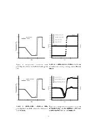
Downloaded by Gecheng Zha on January 16, 2013 | http://arc.aiaa.org | DOI: 10.2514/6.2010-4421<strong>co</strong>ntrolled using a Koso Hammel Dahl <strong>co</strong>mputer <strong>co</strong>ntrolled valve. A vacuum pumpgenerates the necessary low pressure for suction and is <strong>co</strong>ntrolled with a manual needlevalve. Both mass <strong>flow</strong> rates in the injection and suction lines are measured usingOripac orifice mass <strong>flow</strong>meters equipped with high precision MKS pressuretransducers. The aerodynamics variables are measured using an AMTI 6 <strong>co</strong>mponentstransducer. All wind tunnel freestream, CFJ air<strong>flow</strong>, and aerodynamic variables werere<strong>co</strong>rded using a state-<strong>of</strong>-the-art Labview data acquisition system. LE trip was notimplemented since we found that the results are insensitive to the LE trip. All the data(e.g., wind tunnel speed, aerodynamics forces, blowing and suction mass <strong>flow</strong> rates) wereacquired at a rate <strong>of</strong> approximately 50 samples per se<strong>co</strong>nd, allowing for limited <strong>airfoil</strong>flutter analysis around stall angle(s). The range <strong>of</strong> angles <strong>of</strong> attack (AoA) varied between0 o and 30 o . The nominal free stream velocity was V ∞ =10m/s for all tests and the chordReynolds number was about 1.89x10 5 . Similarly to C L and C D , a <strong>jet</strong> momentum<strong>co</strong>efficient Cµ was defined as follows:mV jC (1)21/ 2 V SWith increasing AoA, the pressure over the <strong>airfoil</strong> is expected to decrease andfacilitate the CFJ <strong>jet</strong> penetration. This results in a higher Cµ. Fig. 4 shows the value <strong>of</strong>Cµ and <strong>co</strong>rresponding <strong>jet</strong> velocity for all tests and illustrates that <strong>co</strong>mpensation wasrelatively well achieved for lower Cµ. For this paper, three nominal values <strong>of</strong> Cµ atAoA=0 o are presented: 0.06, 0.15 and 0.25, <strong>co</strong>rresponding to mass <strong>flow</strong> rates <strong>of</strong> 0.030kg/s, 0.045 kg/s and 0.060 kg/s, respectively. The <strong>jet</strong> velocity is varied <strong>co</strong>rrespondingly atabout 23m/s, 34m/s, and 45m/s.Various laser <strong>flow</strong> visualization techniques were used to monitor the circulationover the upper surface. A LaVision Digital Particle Image Velocimetry (DPIV) systemwith a Litron Nano Nd:YAG 200 mJ/pulse was used to monitor and acquire the velocityfield surrounding the <strong>airfoil</strong>. An adaptive 64x64 to 32x32 pixel cross-<strong>co</strong>rrelation analysismethod was used with masking over the <strong>airfoil</strong>, resulting in 75x100 total vectors(including the <strong>airfoil</strong>). A series <strong>of</strong> 1,000 velocity fields were acquired for each AoA andCµ. A customized <strong>flow</strong> seeder using the same particles for PIV tracers was used for <strong>flow</strong>visualization. The <strong>flow</strong> along the span direction was found to be uniform within 1%discrepancies between the root and the tip, while the suction showed a 7% skewnesstoward the root at the suction side. All the results presented were acquired along sectionB, on Fig. 3. III. Large Structure Vortex DetectionFor each series <strong>of</strong> test, the 1,000 instantaneous DPIV samples were averaged to yieldthe mean velocity and vorticity fields. A large structure vortex detection algorithm(VDA) based on Graftiaux et al.[21] was used to describe the vortical structure [2]. Forall grid points P <strong>of</strong> the DPIV grid, the vortex detection function, Γ 1 was calculated over asub-area centered on P. The sub-area size, A M , centered about each velocity grid pointwithin the <strong>flow</strong>, ranged from a 3x3 to 11x11 square grid with a grid node spacing <strong>of</strong> 2.4mm. In other words, the vortex structure size detected will be greater than 2.4x2.4 mm 2 .
The vortex detection function is defined by:1 ( P)AM( PM Uhp( M )) zˆ1dA M dAPM U M A sin()( )M1 (2)AhpADownloaded by Gecheng Zha on January 16, 2013 | http://arc.aiaa.org | DOI: 10.2514/6.2010-4421where M are the discrete grid points within the sub-area, A M , that <strong>co</strong>rrespond to velocitydata points. The larger the value <strong>of</strong> Γ 1, the greater the swirl <strong>co</strong>mponent <strong>of</strong> the <strong>flow</strong> causedby the fluctuating velocity. The criterion |Γ 1 |>0.90 is used to identify a vortex motionwithin the <strong>flow</strong>, where Γ 1 varies between -1 and 1. Based on the sign <strong>of</strong> Γ 1 , the rotation iseither clockwise (CW) or <strong>co</strong>unterclockwise (CCW). Upon detection <strong>of</strong> a vortex, a circle<strong>of</strong> the size <strong>of</strong> the detected vortex is plotted and filled with a <strong>co</strong>lor <strong>co</strong>rresponding to thevortex rotation direction: blue=CW and red=CCW. When applied to the 1,000instantaneous <strong>flow</strong> fields, the VDA results are <strong>co</strong>mpiled into a single figure showing thedistribution <strong>of</strong> the detected vortices.Aerodynamic PerformancesIV. Results and DiscussionWind tunnel results for lift <strong>co</strong>efficient (C L ) and drag <strong>co</strong>efficient (C D ) for thebaseline and CFJ <strong>airfoil</strong>s for different angle <strong>of</strong> attacks and different Cµ are shown inFig.5a and 5b. Compared to baseline, the CFJ <strong>airfoil</strong> shows a dramatic gain in C L and ismaintained with higher values <strong>of</strong> Cµ. Lift increase at AoA=0 o varies between 10% and80% for the range <strong>of</strong> Cµ used. The max C L increase at stall AoA varies between 22% and72% for the range <strong>of</strong> Cµ used.Fig. 6 regroups the performance increase for all Cµ at zero AoA and stalled AoA.These results can be explained by the <strong>co</strong>mbined effect <strong>of</strong> the <strong>co</strong>-<strong>flow</strong> <strong>jet</strong> and suctionincreasing the circulation and preventing <strong>flow</strong> separation. Drag <strong>co</strong>efficient results for theCFJ show a drastic decrease in drag <strong>co</strong>mpared to baseline. Moreover, zero to negativedrag (thrust) can be observed for a large range <strong>of</strong> AoA values. This trend is furtherincreased for higher Cµ. This can be explained by the reduced or reversed wake velocitydeficit resulting in drag reduction and thrust generation [17,18]. Since the aerodynamicefficiency <strong>of</strong> an aircraft is measured by L/D, the CFJ <strong>airfoil</strong> hence <strong>co</strong>uld be an efficientdevice to simultaneously increase lift and reduce drag with certain expense <strong>of</strong> pumpingpower <strong>co</strong>nsumption. The baseline results show a stall occurring around AoA=22°,whereas the CFJ <strong>airfoil</strong> results show a systematic increased stall AoA between AoA=25°and AoA=30° for all Cµ. Due to the large amount <strong>of</strong> data re<strong>co</strong>rded, only the resultspertaining to the <strong>mixing</strong> and <strong>flow</strong> mechanism <strong>of</strong> the CFJ performance increase arepresented here. All the following results are for a freestream velocity <strong>of</strong> U ∞ =10m/s.Two samples <strong>of</strong> instantaneous smoke <strong>flow</strong> visualization for the baseline and CFJ<strong>airfoil</strong> at AoA=25 o are shown in Fig. 7. One can see that the baseline <strong>airfoil</strong> <strong>flow</strong> islargely separated. On the top surface, Kelvin Helmholtz (KH) vortices can be seenshedding from the separation point. The <strong>flow</strong> from the intrado past the TE generates a
large recirculation that feeds the separated wake. In <strong>co</strong>ntrast, the CFJ <strong>airfoil</strong> shows asmooth <strong>flow</strong> hugging the top surface with a thin downward inclined wake past the TE.At low AoA, a closer look at the <strong>jet</strong> <strong>flow</strong> in the vicinity <strong>of</strong> the <strong>jet</strong> exit without andwith CFJ, shown in Fig. 8, reveals a street <strong>of</strong> small KH that dissipates rapidly. The<strong>co</strong>herent vortex structure rotates clockwise with no CFJ, and the rotating direction isreversed with CFJ due to the higher <strong>jet</strong> velocity than that <strong>of</strong> the freestream. The vortexstreet modulates in size with increasing Cµ and disappears for Cµ> 0.14.Downloaded by Gecheng Zha on January 16, 2013 | http://arc.aiaa.org | DOI: 10.2514/6.2010-4421General Mixing CharacteristicsA <strong>co</strong>mparison <strong>of</strong> the time averaged velocity field for baseline with a typical CFJat AoA=25 o is shown in Fig. 9. For clarity, only 1 in 5 vectors are shown in all directions.The baseline <strong>airfoil</strong> shows a large separation originating from the LE, characteristic <strong>of</strong> astalled <strong>airfoil</strong>. The <strong>flow</strong> is observed passing from the TE to the LE all the way to theseparation point and is then entrained in the outer <strong>flow</strong>, creating a shear layer.Instantaneous PIV snapshots show that the shear layer region <strong>co</strong>ntains vortices, but inaverage, the air <strong>flow</strong> appears to merge nicely. The average velocity in the wake isobserved to have a much slower magnitude than the freestream.In <strong>co</strong>ntrast, the CFJ <strong>airfoil</strong> shows a smooth <strong>flow</strong> along the entire surface <strong>of</strong> the<strong>airfoil</strong> with no sign <strong>of</strong> separation. The injection <strong>jet</strong> velocity is about V j /U ∞ =2.2, but aregion <strong>of</strong> high velocity originating from the LE due to the strong LE suction effect isobserved, with values up to V max /U ∞ =3.0. Comparisons <strong>of</strong> the VDA results, shown in Fig.10, provide more information on the vortical structure. For baseline, the shear layer isrevealed with the multiple large CW vortices originating from the <strong>flow</strong> separation point.In <strong>co</strong>ntrast, the VDA results for the CFJ <strong>airfoil</strong> show that no large vortical structure ispresent.The wakes <strong>of</strong> <strong>airfoil</strong>s are always <strong>of</strong> great interest. A <strong>co</strong>mparison <strong>of</strong> the averagevorticity field for baseline and CFJ at Cµ=0.06 at AoA=25 o is shown in Fig. 11. The <strong>flow</strong><strong>of</strong> the baseline <strong>airfoil</strong> from the intrado passes the TE and creates a large shear layer thatturns rapidly horizontal. VDA results (not shown) <strong>co</strong>nfirm that this shear layer<strong>co</strong>rresponds to numerous CCW vortices spatially averaged. Further downstream, the <strong>flow</strong><strong>of</strong> the baseline <strong>airfoil</strong> turns back, creating a large vortical structure. The air in theseparated region <strong>flow</strong>s upstream along the extrado as observed in Fig. 9a. When the CFJin turned ON, the wake <strong>co</strong>nsists in a thin layer with opposite vorticity that extendsdownward with an angle <strong>of</strong> about 25 o from the freestream direction. This shear layer ischaracteristic <strong>of</strong> a <strong>jet</strong>, which reduces the drag or generates thrust depending on theintensity <strong>of</strong> the CFJ[17,18]. The VDA results reveal a few large structure vortices thatdisappear <strong>co</strong>mpletely for higher Cµ.Fig. 12 to 14 show the time averaged PIV CFJ <strong>airfoil</strong> velocity fields and theVDA results for AoA=30 o for all three Cµ. For the lower Cµ=0.06, one can see that the<strong>flow</strong> is largely separated since the CFJ is not strong enough to achieve attached <strong>flow</strong> atsuch high AoA. The outer <strong>flow</strong> shear layer is seen shedding numerous CW (blue)vortices. Between the outer <strong>flow</strong> and the <strong>jet</strong> <strong>flow</strong>, the <strong>flow</strong> can be observed travelingupstream to meet the separation point, which is reminiscent <strong>of</strong> the baseline stalled <strong>flow</strong>.The upstream <strong>flow</strong> strip (UFS) is “sandwiched” between the outer shear layergenerating CCW vortices and the <strong>flow</strong> induced by the CFJ injection that produces CW
Downloaded by Gecheng Zha on January 16, 2013 | http://arc.aiaa.org | DOI: 10.2514/6.2010-4421vortices. The UFS is a region <strong>of</strong> large vortex free. Below the UFS, the <strong>jet</strong> appears todecay rapidly and strongly interact with the return <strong>flow</strong> from the TE.A white triangular marker and a dash line indicate the location <strong>of</strong> the saddle pointarea. The <strong>jet</strong> is deflected normally to the <strong>airfoil</strong> surface feeding the UFS and the outershear layer. The <strong>jet</strong>-to-return saddle point area is characterized by a rapid change fromthe CCW vortex <strong>of</strong> outer shear layer to the CW vortices induced by the CFJ. With theincreased Cµ, the saddle point is pushed downstream along the <strong>airfoil</strong> surface. The UFSbe<strong>co</strong>mes thinner and the large vortices appear to increase in number and size. Finally, theresults for the higher Cµ=0.25 are shown in Fig. 14. The UFS appears to be <strong>co</strong>mpletelysuppressed, the number <strong>of</strong> vortices is greatly decreased and the saddle point is, again,pushed further downstream. Inspection <strong>of</strong> instantaneous samples <strong>co</strong>nfirms that the abovefeatures are not artifact from the averaging process and show that the UFS is a<strong>co</strong>mbination <strong>of</strong> pairing <strong>of</strong> two <strong>co</strong>unter-rotating vortices funneling <strong>flow</strong> from the wake tothe LE separation point, as shown in Fig. 15a. The <strong>jet</strong> deflection normal to the surfacealso appears to be eased by outer shear layer CW rollups, as seen in Fig. 15b. The <strong>flow</strong> inthe vicinity <strong>of</strong> the TE for Cµ=0.25 is shown in Fig. 16. While the <strong>jet</strong> action <strong>of</strong> delayingthe separation benefits to the <strong>airfoil</strong> circulation, the suction appears to slightly acceleratethe <strong>flow</strong> from the TE in the upstream direction. The wake is typical <strong>of</strong> a separated <strong>flow</strong>.CW vortices are observed on top <strong>of</strong> the shear layer with the “delayed” outer <strong>flow</strong> andCCW vortices are shedding <strong>of</strong>f the TE and the shear layer <strong>flow</strong> from the intrado.Turbulent MixingCombining the time averaged velocity and VDA results provides ampleinformation on the mean and the vortical characteristics <strong>of</strong> the <strong>flow</strong>, but <strong>mixing</strong> shouldalso be <strong>co</strong>nsidered through non-vortical fluctuations. The intermittent characteristics <strong>of</strong>the <strong>flow</strong> can be observed using the turbulent kinetic energy field (TKE). CorrespondingTKE fields for Fig. 12-16 are shown in Fig 17 to Fig. 19. For Cµ=0.06, most TKEoriginates in the <strong>jet</strong> area, indicative <strong>of</strong> the high velocity gradient caused by the injection<strong>jet</strong> penetration. The outer shear layer starting from LE and stretching to downstreamalso shows high value TKE, again mostly due to the high velocity gradient between thehigh speed free stream and the UFS. While the wake above the TE shows very low levels<strong>of</strong> fluctuation, the area below the TE shear layer shows very high TKE values, indicative<strong>of</strong> a high intensity shear layer between the <strong>flow</strong> from the upper suction surface and lowerpressure surface, as shown in Fig. 7. The TE shear layer turbulence intensity is reducedwhen Cµ is increased. This is because the increased CFJ intensity decreases the velocitydissimilarity between the suction and pressure surface.For Cµ=0.25 shown in Fig. 19, the LE separation point and the CFJ injection areashows the highest value <strong>of</strong> TKE. The <strong>flow</strong> is about to be attached. Observations <strong>of</strong>instantaneous DPIV velocity fields shows that an intermittent <strong>flow</strong> pattern is establishedwith either a separated <strong>flow</strong> or a re-attached <strong>flow</strong>. In <strong>co</strong>ntrast, past the TE, the level <strong>of</strong>turbulence in the wake is largely decreased due to reduced wake velocity deficit. Theincreased turbulence intensity at the CFJ injection area indicates the increasedturbulence <strong>mixing</strong> intensity, which transports high kinetic energy from the <strong>jet</strong> to the main<strong>flow</strong> so that the main <strong>flow</strong> can over<strong>co</strong>me the severe adverse pressure gradient at highAoA and remain attached.
When the <strong>flow</strong> is attached, the turbulence kinetic energy is significantly reduceddue to the disappearance <strong>of</strong> large structure vortices as shown from Fig. 20 to 22.IV. ConclusionDownloaded by Gecheng Zha on January 16, 2013 | http://arc.aiaa.org | DOI: 10.2514/6.2010-4421The turbulence <strong>mixing</strong> mechanism <strong>of</strong> a CFJ <strong>airfoil</strong> is investigated in this paper. Atlow AoA and low momentum <strong>co</strong>efficient, the <strong>mixing</strong> between the wall <strong>jet</strong> and main<strong>flow</strong>is dominant with large structure <strong>co</strong>herent structures for the attached <strong>flow</strong>s. When themomentum <strong>co</strong>efficient is increased, the large vortex structure disappears.At high AoA with <strong>flow</strong> separation, the CFJ creates a upstream <strong>flow</strong> strip betweentwo <strong>co</strong>unter rotating vertical shear layer, i.e., the outer shear layer and inner <strong>flow</strong>induced by CFJ. The UFS is characterized with large vortex free region. The <strong>co</strong>-<strong>flow</strong> wall<strong>jet</strong> is deflected normal to the <strong>airfoil</strong> surface characterized with a saddle point. Withincreased momentum <strong>co</strong>efficient <strong>of</strong> the CFJ, the saddle point moves downstream andeventually disappears when the <strong>flow</strong> is attached.Turbulence plays a key role in <strong>mixing</strong> the CFJ with main<strong>flow</strong> to transport highkinetic energy from the <strong>jet</strong> to main<strong>flow</strong> so that the main<strong>flow</strong> can remain attached at highAoA to generate high lift. When the <strong>flow</strong> is separated, increased CFJ momentum<strong>co</strong>efficient also increases the turbulence intensity at <strong>jet</strong> injection <strong>mixing</strong> region. Whenthe <strong>flow</strong> is attached, the turbulence kinetic energy is significantly reduced due todisappearance <strong>of</strong> large structure vortices.Acknowledgement:This research is supported under ARO/AFOSR Grant 50827-RT-1SP. Weappreciate the assistance from P. Ly, M. Castillo, A. Beaudry and K. Chin-Sim foroperating the wind tunnel tests.REFERENCES[1] W. L. I. Sellers, B. A. Singer, and L. D. Leavitt, “Aerodynamics for RevolutionaryAir Vehicles.” AIAA 2004-3785, June 2003.[2] M. Gad-el Hak, “Flow Control: The Future ,” Journal <strong>of</strong> Aircraft, vol. 38, pp. 402–418, 2001.[3] M. Gad-el Hak, Flow Control, Passive, Active, and Reactive Flow Management.Cambridge University Press, 2000.[4] S. Anders, W. L. Sellers, and A. Washburn, “Active Flow Control Activities at NASALangley.” AIAA 2004-2623, June 2004.[5] C. P. Tilmann, R. L. Kimmel, G. Addington, and J. H. Myatt, “Flow Control Researchand Application at the AFRL’s Air Vehicles Directorate.” AIAA 2004-2622, June 2004.[6] D. Miller, , and G. Addington, “Aerodynamic Flowfield Control Technologies forHighly
Integrated Airframe Propulsion Flowpaths.” AIAA 2004-2625, June 2004.[7] V. Kibens and W. W. Bower, “An Overview <strong>of</strong> Active Flow Control Applications atThe Boeing Company.” AIAA 2004-2624, June 2004.[8] R. Holman, Y. Utturkar, R. Mittal, and L. Cattafesta, “Formation Criterion forSynthetic Jets,” AIAA Journal, vol. 43, No. 10, pp. 2110–2116, 2005.[9] T. C. Corke and M. L. Post, “ Overview <strong>of</strong> Plasma Flow Control: Concepts,Optimization, and Applications.” AIAA Paper 2005-0563, Jan. 2005.[10] C. Enloe, T. E. McLaughlin, G. I. Font, and J. W. Baughn, “ Frequency Effects onthe Efficiency <strong>of</strong> Aerodynamic Plasma Actuator .” AIAA Paper 2006-0166, Jan. 2006.Downloaded by Gecheng Zha on January 16, 2013 | http://arc.aiaa.org | DOI: 10.2514/6.2010-4421[11] Raman, G. , “ Using <strong>co</strong>ntrolled unsteady fluid mass addition to enhance <strong>jet</strong> <strong>mixing</strong>.,” AIAA Journal, vol. 35, No. 4, pp. 647–656, 1997.[12] Freund, J.B. and Moin, P. , “ Jet <strong>mixing</strong> enhancement by high-amplitude fluidicactuation,” AIAA Journal, vol. 38, No. 10, pp. 1863–1870, 2000.[13] N. Wood and J. Nielsen, “Circulation Control Airfoils-Past, Present, Future.” AIAAPaper 85-0204, 1985.[14] R. J. Englar, “Circulation Control Pneumatic Aerodynamics: Blown Force andMoment Augmentation and Modifications; Past, Present and Future.” AIAA 2000-2541,June 2000.[15] M. Wilson and C. von Kerczek, “An Inventory <strong>of</strong> Some Force Procedure for Use inMarine Vehicle Control.” DTNSRDC-791097, Nov, 1979.[16] G. S. Jones, “Pneumatic Flap Performance for a 2D Circulation Control Airfoil,Steady & Pulsed.” Applications <strong>of</strong> Circulation Control Technologies, Chapter 7, p. 191-244, Vol. 214,Progress in Astronautics and Aeronautics, AIAA Book Series, Editors: Joslin, R. D. andJones, G. S., 2006.[17] G.-C. Zha, W. Gao, and C. Paxton, “Jet Effects on Co-Flow Jet AirfoilPerformance,” AIAAJournal, No. 6,, vol. 45, pp. 1222–1231, 2007.[18] G.-C. Zha and D. C. Paxton, “A Novel Flow Control Method for AirfoilPerformance Enhancement Using Co-Flow Jet.” Applications <strong>of</strong> Circulation ControlTechnologies, Chapter 10, p. 293-314, Vol. 214, Progress in Astronautics andAeronautics, AIAA Book Series, Editors: Joslin, R. D. and Jones, G.S., 2006.[19] G.-C. Zha, C. Paxton, A. Conley, A. Wells, and B. Carroll, “Effect <strong>of</strong> Injection SlotSize on High Performance Co-Flow Jet Airfoil,” AIAA Journal <strong>of</strong> Aircraft, vol. 43, 2006.
Downloaded by Gecheng Zha on January 16, 2013 | http://arc.aiaa.org | DOI: 10.2514/6.2010-4421[20] G.-C. Zha, B. Carroll, C. Paxton, A. Conley, and A. Wells, “High PerformanceAirfoil with Co-Flow Jet Flow Control,” AIAA Journal, vol. 45, 2007.[21] Graftieaux, L., Michard, M. and Grosjean, N., 2001. “Combining PIV, POD andvortex identification algorithms for the study <strong>of</strong> unsteady turbulent swirling <strong>flow</strong>s”,Meas. Sci. Technol., 12, pp. 1422-1429.[22] Dano, P.E., and Liburdy, J.A., “Vortical Structure <strong>of</strong> a 45 o Inclined Pulsed Jet in aCross<strong>flow</strong>”, AIAA-2006-3543,2006.[23] Zha, G.-C., Gao, W. and Paxton, C. D. "Jet Effects on Co-Flow Jet AirfoilPerformance ", AIAA Journal, Vol.45, No.6, 2007, pp1222-1231
Fig. 1. Schematic and <strong>co</strong>ncept <strong>of</strong> CFJ <strong>airfoil</strong>Downloaded by Gecheng Zha on January 16, 2013 | http://arc.aiaa.org | DOI: 10.2514/6.2010-4421Fig. 2 Wind tunnel facilityCBAFig. 3 CFJ <strong>airfoil</strong> and PIV plans locationsFig. 4 Variation <strong>of</strong> Cµ and <strong>jet</strong> exit velocity for various AoA
(a)(b)Downloaded by Gecheng Zha on January 16, 2013 | http://arc.aiaa.org | DOI: 10.2514/6.2010-4421Lift Improvement (%)90%80%70%60%50%40%30%20%10%0%20%at AoA=0degat Stall AoA35%Fig. 5 Lift and Drag <strong>co</strong>efficient results <strong>co</strong>mparisonfor baseline and CFJ at various AoA and Cµ46%59%0.06 0.14 0.25Cµ77% 82%Drag Reduction (%)1200%1000%800%600%400%200%0%at AoA=0degat Stall AoA92% 53%445%58%1009%0.06 0.14 0.25CµFig. 6 Performance enhancement at zero AoA and stall AoA.(a)(b)65%Fig. 7 Smoke <strong>flow</strong> visualization for (a) Baseline and (b) CFJ (Cµ=0.14) at AoA=25 o
(a)Downloaded by Gecheng Zha on January 16, 2013 | http://arc.aiaa.org | DOI: 10.2514/6.2010-4421(b)Fig. 8 Close-up <strong>flow</strong> visualization for CFJ at(a) Cµ=0 and (b) Cµ=0.02 for AoA=5 o
(a)(b)Downloaded by Gecheng Zha on January 16, 2013 | http://arc.aiaa.org | DOI: 10.2514/6.2010-4421Fig. 9 Time averaged velocity field at leading edge, for (a) baseline and(b) CFJ (Cµ=0.06) for AoA=25 o(a)Fig. 10 VDA results at the leading edge for (a) baseline and(b) CFJ (Cµ=0.06) for AoA=25 o(a)(b)(b)Fig. 11 Time averaged vorticity field at the trailing edge for (a) Cµ=0and (b) Cµ=0.25 for AoA=25 o
(a)(b)Fig. 12 Leading edge results for (a) mean velocity and (b) VDA for Cµ=0.06 andAoA=30 oDownloaded by Gecheng Zha on January 16, 2013 | http://arc.aiaa.org | DOI: 10.2514/6.2010-4421(a)Fig. 13 Leading edge results for (a) average velocity field and (b) VDA for Cµ=0.14 andAoA=30 o(a)(b)(b)Fig. 14 Leading edge results for (a) average velocity field and (b) VDA for Cµ=0.25 andAoA=30 o
(a)Downloaded by Gecheng Zha on January 16, 2013 | http://arc.aiaa.org | DOI: 10.2514/6.2010-4421(b)Fig. 15 Instantaneous DPIV samples Cµ=0.06 and AoA=30 o
(a)(b)Downloaded by Gecheng Zha on January 16, 2013 | http://arc.aiaa.org | DOI: 10.2514/6.2010-4421Fig. 16 Trailing edge results for (a) average velocity field and (b) VDA for Cµ=0.25 andAoA=30 o(a)(b)Fig. 17 TKE fields at (a) Leading edge and (b) trailing edge for Cµ=0.06 and AoA=30 o(a)Fig. 18 TKE fields at (a) Leading edge and (b) trailing edge for Cµ=0.14 and AoA=30 o(b)(a)(b)Fig. 19 TKE fields at (a) Leading edge and (b) trailing edge for Cµ=0.25 and AoA=30 o
(a)(b)Fig. 20 TKE fields at (a) Leading edge and (b) trailing edge for Cµ=0.06 and AoA=25 oDownloaded by Gecheng Zha on January 16, 2013 | http://arc.aiaa.org | DOI: 10.2514/6.2010-4421(a)(b)Fig. 21 TKE fields at (a) Leading edge and (b) trailing edge for Cµ=0.14 and AoA=25 o(a)(b)Fig. 22 TKE fields at (a) Leading edge and (b) trailing edge for Cµ=0.25 and AoA=25 o