Grundfos Alldos DME 2-48 O&M Manual - WES Dosing Products
Grundfos Alldos DME 2-48 O&M Manual - WES Dosing Products
Grundfos Alldos DME 2-48 O&M Manual - WES Dosing Products
- No tags were found...

You also want an ePaper? Increase the reach of your titles
YUMPU automatically turns print PDFs into web optimized ePapers that Google loves.
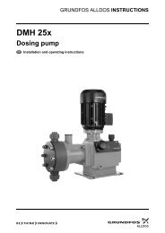
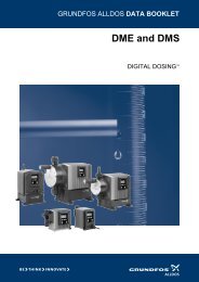
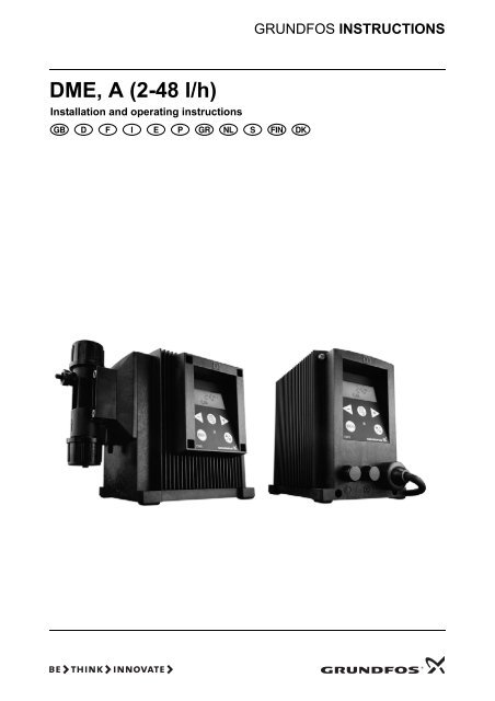
GRUNDFOS INSTRUCTIONS<strong>DME</strong>, A (2-<strong>48</strong> l/h)Installation and operating instructions
<strong>DME</strong>Installation and operating instructions 4Montage- und Betriebsanleitung 30Notice d’installation et d’entretien 57Istruzioni di installazione e funzionamento 83Instrucciones de instalación y funcionamiento 109Instruções de instalação e funcionamento 135Οδηγίες εγκατάστασης και λειτουργίας 161Installatie- en bedieningsinstructies 187Monterings- och driftsinstruktion 213Asennus- ja käyttöohjeet 239FINMonterings- og driftsinstruktion 2653
CONTENTSPage1. General description 41.1 Applications 41.2 Type key 52. Technical data 62.1 Mechanical data 62.2 Electrical data 62.3 Input/output data 62.4 Dimensions 73. Installation 73.1 Safety instructions 73.2 Installation environment 73.3 Installation of pump 73.4 Installation example 83.5 Electrical connection 83.6 Connection overview 94. Functions 104.1 Control panel 104.2 Start/stop of pump 114.3 Priming/venting of pump 114.4 Level control 114.5 Indicator lights and alarm output 114.6 Fieldbus communication 124.7 Menu 134.8 Operating modes 144.9 <strong>Manual</strong> 144.10 Pulse 144.11 Analog 144.12 Timer 164.13 Batch 174.14 Anti-cavitation 174.15 Capacity limitation 184.16 Counters 184.17 Resetting 194.18 Return 194.19 Language 194.20 Input setup 204.21 Measuring units 214.22 <strong>Dosing</strong> monitoring 224.23 Control panel lock 235. Start-up 246. Calibration 256.1 Direct calibration 266.2 Indirect calibration 276.3 Check calibration 287. Maintenance 288. Service 289. Fault finding chart 2910. Disposal 291. General descriptionThe <strong>Grundfos</strong> <strong>DME</strong> dosing pump is a self-priming diaphragmpump.The pump consists of:• a cabinet incorporating the drive unit and electronics,• a dosing head with back plate, diaphragm,valves, connections and vent valve,• a control panel incorporating display and buttons.The control panel can be fitted either to the end orto the side of the cabinet.Being equipped with a stepper motor, this dosingpump is unique in its field. The stepper motor offersthe possibility of varying the capacity by changingthe duration of the dosing stroke.Furthermore, the motor is controlled in such a waythat the dosing gets as even and constant as possible,irrespective of the capacity range in which thepump is operating.This is carried out as follows:The speed of the suction stroke is kept constant andthe stroke relatively short, irrespective of the capacity.Contrary to conventional pumps, which generatethe dosing stroke as a short pulse, the duration ofthe dosing stroke will be as long as possible. Thus,an even dosing without peak values is ensured. Asthe pump is always dosing at full stroke length, it ensuresthe same high accuracy and suction capability,irrespective of the capacity, which is infinitely variablein the ratio of 1:1000.The pump features an LCD display and a userfriendlycontrol panel which gives access to thepump functions.1.1 ApplicationsThe <strong>DME</strong> dosing pump is designed for handlingchemicals within the following ranges of applications,among others:• Drinking water treatment.• Wastewater treatment.• Swimming pool water treatment.• Boiler water treatment.• Cooling water treatment.• Process water treatment.• Washing systems.Before beginning installation procedures,these installation and operating instructionsshould be studied carefully. The installationand operation should also be inaccordance with local regulations and acceptedcodes of good practice.4
1.2 Type key(Cannot be used for pump configuration.)Example: <strong>DME</strong> 2-18 A-PP/E/C-F-3 1 1E FPump range <strong>DME</strong> ..Maximum pressure [bar]Control variantCodeStandardAStandard + alarm relay ARStandard + Profibus APStandard + GENIbus AG<strong>Dosing</strong> head material CodePolypropylenePPPVDFPVStainless steel 1.4401 SSGasket material CodeEP<strong>DME</strong>FKMVValve ball material CodeCeramicsCStainless steel 1.4401 SSCode Mains plugF EU (Schuko)B USA, CANG UKI AUE CHJ JPCodeConnection,suction/discharge1 Tubing 6/9Tubing 4/6supplied with the pump2 Tubing 6/9Tubing 6/12+9/12supplied with the pump3 Tubing 4/64 Tubing 6/95 Tubing 6/126 Tubing 9/12A Threaded Rp 1/4B Threaded Rp 3/8E Cementing d.10F Cementing d.12Control panelFront-fittedSide-fittedCodeFSCode Valves1 Standard valve2 Spring-loaded valveVoltageCode1 x 100-240 V, 50-60 Hz 35
2. Technical data2.1 Mechanical data<strong>DME</strong> 2 <strong>DME</strong> 8 <strong>DME</strong> 12 <strong>DME</strong> 19 <strong>DME</strong> <strong>48</strong>Maximum capacity without anti-cavitation * 1 [l/h] 2.5 7.5 12 18.5 <strong>48</strong>Maximum capacity with anti-cavitation * 1 [l/h] 1.8 5.6 9 14.5 37Maximum pressure [bar] 18 10 6 6.2 2.6Maximum stroke rate per minute [stroke/min.] 180 180 180 151 151Maximum suction lift during operation [m] 6Maximum suction lift when priming with wet valves [m] 1.8 3 3 3 3Maximum viscosity with spring-loaded valves * 2 [mPas] 500 500 500 500 100Maximum viscosity without spring-loaded valves * 2[mPas]200 200 200 200 100Diaphragm diameter [mm] 28 38 42.5 55 77Liquid temperature [°C] 0 to 50Ambient temperature [°C] 0 to 45Accuracy of repeatability ±1%Sound pressure level [dB(A)]
2.4 DimensionsSee dimensions at the end of these instructions.All dimensions are in mm.3. Installation3.1 Safety instructions• The liquid is under pressure and may be hazardous.• When working with chemicals, local safety rulesand regulations must be observed (e.g. wear protectiveclothes).• Before starting work on the dosing pump and system,disconnect the electricity supply to the pump,ensuring that it cannot be accidentally switchedon. Before reconnecting the electricity supply,make sure that the dosing hose is positioned insuch a way that any chemical left in the dosinghead is not ejected, thereby exposing persons todanger.• If the vent valve in the dosing head is used, it mustbe connected to a hose which is led back to thetank.• When changing a chemical, make sure that thematerials of the dosing pump and system are resistantto the new chemical. If there is any risk ofchemical reaction between the two types of chemicals,clean the pump and system thoroughly beforeadding the new chemical.Proceed as follows:Place the suction tube in water and press the 100%button until residual chemical has been removed.Note: When the buttons 100% and are pressedsimultaneously, the pump can be set to run for aspecific number of seconds at maximum capacity.The remaining number of seconds will appear inthe display. The maximum value is 300 seconds.3.3 Installation of pump• See also the installation example in section 3.4.• Note: The dosing head may contain water fromthe factory test. If a liquid which must not comeinto contact with water is to be dosed, it is recommendedto let the pump run with another liquid toremove the water from the dosing head before installation.• Note: Tighten the bolts in the dosing head after2 to 5 operating hours (torque 5 Nm).• Always install the pump on the supporting footwith vertical suction and discharge ports.• Always use suitable tools for the mounting of plasticparts. Never apply unnecessary force.• Make sure that the dosing pump and system aredesigned in such a way that neither system equipmentnor buildings are damaged in case of leakagefrom the pump or rupture of hoses/pipes. Theinstallation of leakage hoses and collecting tanksis recommended.• Make sure that the drain hole in the dosing headpoints downwards, see fig. 1.Note: It is important that the drain pipe/hole is notinserted direct into the tank contents, as gassesmay penetrate into the pump.Fig. 1Drain holeTM01 8420 50993.2 Installation environment• Exposure to direct sunlight should be avoided.This applies especially to pumps with plastic dosingheads, as this material can be damaged bysunlight.• If the pump is installed outside, an enclosure orsimilar protection is required to protect the pumpagainst rain and similar weathers.7
3.4 Installation exampleThe drawing in fig. 2 shows an installation example.Fig. 2The <strong>DME</strong> pump can be installed in many different ways. The sketch below shows an example with sidefittedcontrol panel. The tank is a <strong>Grundfos</strong> chemical tank with a <strong>Grundfos</strong> level control unit.TM01 8421 02043.5 Electrical connection• The electrical connection of the pump should becarried out by qualified persons in accordancewith local regulations.• For electrical data of the pump, see section 2.2.• Do not lay signal cables, if any, together withpower cables.8
4. Functions4.1 Control panelFig. 4LCD display,see section 4.7Navigation/settings,see section 4.7Maximum capacity(priming),see section 4.3ml/hNavigation/settings,see section 4.7100%Menu,see section 4.7Greenindicator light,see section 4.5On/off button,see section 4.7Redindicator light,see section 4.5Connectionalarm relay/bus.Control variants“AR”, “AP” and “AG”,see sections 4.5 and4.6M12 connectionpulse/analog input,see section 4.4M12 connectionlevel control,see section 4.4Mains connectionTM01 8423 010010
4.2 Start/stop of pumpThe pump can be started/stopped in two differentways:• Locally on the pump control panel.• By means of an external on/off switch connectedto the pulse input. See connection overview insection 3.6.4.3 Priming/venting of pumpThe pump control panel incorporates a 100% button.Press this button if the maximum pump capacity isrequired over a short period, e.g. during start-up.When the button is released, the pump automaticallyreturns to the previous operating mode.During priming/venting, it is recommended to let thepump run without a counter pressure or to loosen thevent valve by giving it a 1/8 to 1/4 turn.Note: When the buttons 100% and are pressed simultaneously,the pump can be set to run for a specificnumber of seconds at maximum capacity. Theremaining number of seconds will appear in the display.The maximum value is 300 seconds.4.4 Level controlThe pump can be fitted with a level control unit formonitoring of the chemical level in the tank.The pump can react to two level signals. The pumpwill react differently, depending on the influence onthe individual level sensors.The functions of the indicator lights and the built-inalarm relay appear from the table below:ConditionPumprunningSet to stopGreenLEDOnDisplayFlashingRedLEDOffOffNormalindicationNormalindicationPump fault Off On EEPROMSupplyfailureOff Off OffPump running,lowchemicalOn Onlevel 2NormalindicationAlarmoutput 11 2 3NC NO C1 2 3NC NO C1 2 3NC NO C1 2 3NC NO C1 2 3NC NO CLevel sensorsUpper sensoractivated(closed contact)Lower sensoractivated(closed contact)Pump reaction• Red indicator light is on.• Pump running.• Alarm relay activated.*• Red indicator light is on.• Pump stopped.• Alarm relay activated.** Control variant “AR” only.See section 3.6 for connection of the level controlunit and alarm output.4.5 Indicator lights and alarm outputThe green and red indicator lights on the pump areused for operating and fault indication.In control variant “AR”, the pump can activate an externalalarm signal by means of a built-in alarm relay.The alarm signal is activated by means of an internalpotential-free contact.Emptytank 2 Off OnAnalogsignal< 2 mAOffOnThe dosedquantity istoo smallaccordingto the signalfrom thedosingmonitor 3 On OnOverheatingOffOnNormalindicationNormalindicationNormalindicationMAX.TEMP.1 2 3NC NO C1 2 3NC NO C1 2 3NC NO C1 2 3NC NO C1 Control variant AR only.2 Requires connection to level sensors.3 Requires activation of the dosing monitoringfunction and connection to a dosing monitor.11
4.6 Fieldbus communicationThe pump can be configured for fieldbus applications.The following bus types are available:Control variantAPAGBus typeProfibusGENIbusSeparate instructions are supplied with each bustype.12
4.7 MenuThe pump features a user-friendly menu which is activatedby pressing the button. During start-up, alltexts will appear in English language. To select language,see section 4.19.Fig. 5All menu items are described in the following sections.When appears at a menu item, it meansthat this item is activated. By selecting “RETURN”anywhere in the menu structure, you will return to theoperating display without changes.See section 4.9 See section 4.23See section 4.10 See section 4.17See section 4.11 See section 4.18See section 4.12 See section 4.19See section 4.13 See section 4.15See section 4.14 See section 4.20See section 6 See section 4.21See section 4.1613
4.8 Operating modesNote: The displayed l and ml values are only reliableif the pump has been calibrated to the actual installation,see section 6.The pump can run in five different operating modes:• <strong>Manual</strong>• Pulse• Analog• Timer (internal batch control)• Batch (external batch control)See description in the following sections.4.9 <strong>Manual</strong>The pump is dosing as constantly and evenly as possible,without any external signals.Set the quantity to be dosed in l/h or ml/h. The pumpautomatically changes over between the measuringunits.Setting range:<strong>DME</strong> 2: 2.5 ml/h - 2.5 (1.8*) l/h<strong>DME</strong> 8: 7.5 ml/h - 7.5 (5.6*) l/h<strong>DME</strong> 12: 12 ml/h - 12 (9*) l/h<strong>DME</strong> 19: 18.5 ml/h - 18.5 (14.5*) l/h<strong>DME</strong> <strong>48</strong>: <strong>48</strong> ml/h - <strong>48</strong> (37*) l/h* The figures in brackets indicate the maximum capacitywhen the anti-cavitation function is activated.Fig. 6Set value4.10 PulseThe pump is dosing according to an external pulsesignal, i.e. a water meter with pulse output or a controller.Set the quantity to be dosed per pulse in ml/pulse.The pump adjusts its capacity according to two factors:• Frequency of external pulses.• The set quantity per pulse.Setting range:<strong>DME</strong> 2: 0.000018 ml/pulse - 5 ml/pulse<strong>DME</strong> 8: 0.000069 ml/pulse - 15 ml/pulse<strong>DME</strong> 12: 0.000111 ml/pulse - 24 ml/pulse<strong>DME</strong> 19: 0.000204 ml/pulse - 37 ml/pulse<strong>DME</strong> <strong>48</strong>: 0.00530 ml/pulse - 96 ml/pulseFig. 7Set quantity inml/pulseActual capacityin ml/h or l/hIf the set quantity per pulse multiplied by the pulsefrequency exceeds the pump capacity, the pump willrun at maximum capacity. Excess pulses will be ignoredand the “actual capacity” display will flash.4.11 AnalogThe pump is dosing according to an external analogsignal. The dosed quantity is proportional to the inputvalue in mA.4-20 (default): 4 mA = 0%.20 mA = 100%.20-4: 4 mA = 100%.20 mA = 0%.0-20: 0 mA = 0%.20 mA = 100%.20-0: 0 mA = 100%.20 mA = 0%.See fig. 8.The capacity limitation will influence the capacity.100% corresponds to the maximum capacity of thepump or the set maximum capacity, see section4.15.Fig. 8[%]100806040200-20 mA4-20 mA00 4 8 12 16 20[mA]TM02 4498 110214
Fig. 9Valueaccording toanalog signalIf 4-20 mA or 20-4 mA is selected and the signal fallsbelow 2 mA, the pump will indicate a fault. This situationoccurs if the connection is interrupted, for instanceif the wire is damaged.Change the analog mode as illustrated in fig. 10:Fig. 10Use the buttonsfor navigation15
4.12 TimerThe pump is dosing the set quantity in batches at themaximum capacity or the set maximum capacity, seesection 4.15.The time until the first dosing “NX” and the followingsequences “IN” can be set in minutes, hours anddays. The maximum time limit is 9 days, 23 hoursand 59 minutes (9:23:59). The lowest acceptablevalue is 1 minute. The internal timer continues evenif the pump is stopped by means of the on/off button,empty tank or stop signal, see fig. 11.During operation, “NX” will always count down from“IN” to zero. In this way, the remaining time until thenext batch can always be read.“IN” must be higher than the time required to performone batch. If “IN” is lower, the next batch will be ignored.In case of supply failure, the set quantity to bedosed, the “IN” time and the remaining “NX” time arestored. When the supply is reconnected, the pumpwill start up with the “NX” time at the time of the supplyfailure. In this way, the timer cycle will continue,but it has been delayed by the duration of the supplyfailure.Fig. 11Quantity per batchFig. 12Set quantityper batchSet IN valuein minutesSet IN valuein hoursNXINTM01 8942 0900Set IN valuein daysSetting range:<strong>DME</strong> 2: 0.23 ml/batch - 5 l/batch<strong>DME</strong> 8: 0.69 ml/batch - 15 l/batch<strong>DME</strong> 12: 1.11 ml/batch - 24 l/batch<strong>DME</strong> 19: 2.04 ml/batch - 37 l/batch<strong>DME</strong> <strong>48</strong>: 5.3 ml/batch - 96 l/batchOnly values corresponding to complete dosingstrokes (according to the calibration factor) can beselected.Example: If the calibration factor is 23.3 (= 0.233 ml/stroke), the minimum settable value in timer or batchmode will be 0.233 ml -> the next will be 0.466 ml ->the next will be 0.699 ml, etc.These steps will continue up to a value correspondingto 100 dosing strokes. Above this value, the settingrange has standard steps as in other operatingmodes.If the calibration factor is changed after setting oftimer or batch mode, the pump will automatically recalculatea new amount of dosing strokes per batchand change the display value to the nearest possiblevalue compared to the first one set.Set NX valuein minutesSet NX valuein hoursSet NX valuein days16
4.13 BatchThe pump is dosing the set quantity in batches at themaximum capacity or the set maximum capacity, seesection 4.15.The quantity is dosed every time the pump receivesan external pulse.If the pump receives new pulses before the previousbatch is performed, these pulses will be ignored.Fig. 13Fig. 14Set valueper batchQuantity per batchThe setting range is the same as for Timer, see section4.12.Fig. 15PulsePulseTM01 8947 09004.14 Anti-cavitationThe pump features an anti-cavitation function. Whenthis function is selected, the pump extends andsmooths its suction stroke, resulting in softer priming.The anti-cavitation function is used:• when pumping liquids of high viscosity,• in the case of a long suction tube and• in the case of a high suction lift.The maximum pump capacity is reduced when thisfunction is selected. See section 2.1 Mechanicaldata.Operating display17
4.15 Capacity limitationThis function offers the possibility of reducing themaximum pump capacity (MAX CAP). It influencesthe functions in which the pump is normally operatingat maximum capacity.Under normal operating conditions, the pump cannotoperate at a capacity which is higher than the onestated in the display. This does not apply to the maximumcapacity button 100% , see section 4.3.Fig. 16Fig. 17Total dosedquantitySet maximumcapacityTotal numberof strokesOperating display4.16 CountersThe pump can display “non-resettable” counters for:• “QUANTITY”Accumulated value of dosed quantity in litres orUS gallons.• “STROKES”Accumulated number of dosing strokes.• “HOURS”Accumulated number of operating hours.• “POWER ON”Accumulated number of times the electricity supplyhas been switched on.Total numberof operatinghoursTotal numberof startsOperating display18
4.17 ResettingWhen “DEFAULT” is activated, the pump will returnto the factory settings.Fig. 18Note: The calibration is also set back to the defaultsetting. This means that a new calibration is requiredwhen the “DEFAULT” function has been used.Operating displayOperating displaywithout changes4.18 ReturnFig. 19The “RETURN” function makes it possible to returnfrom any level in the menu to the operating displaywithout changes after the menu functions have beenused.4.19 LanguageThe display text can be displayed in one of the followinglanguages:• English• German• French• Italian• Spanish• Portuguese• Dutch• Swedish• Finnish• Danish• Czech• Slovak• Polish• Russian19
Fig. 20Operating display Operating display Operating displaywithout changes4.20 Input setupFig. 21 shows all possible settings.The level and stop inputs can be changed from NO(normally open) to NC (normally closed) function. Ifchanged, the inputs must be short-circuited in normaloperation.Fig. 21For the analog input, one of the following signaltypes can be selected:• 4-20 mA (default),• 20-4 mA,• 0-20 mA,• 20-0 mA.See also section 4.11 Analog.Change the level input to an input for dosing monitoringas illustrated in fig. 21.Use the buttonsfor navigation20
4.21 Measuring unitsIt is possible to select metric units (litre/millilitre) orUS units (gallons/millilitre).Metric measuring units:• In manual and analog modes, set the quantity tobe dosed in litres per hour (l/h) or millilitres perhour (ml/h).• In pulse mode, set the quantity to be dosed inml/pulse. The actual capacity is indicated in litresper hour (l/h) or millilitres per hour (ml/h).• For calibration, set the quantity to be dosed inml per 100 strokes.• In timer and batch modes, set the quantity to bedosed in litres (l) or millilitres (ml).• Under the “QUANTITY” menu item in the“COUNTERS” menu, the dosed quantity is indicatedin litres.Fig. 22US measuring units:• In manual and analog modes, set the quantity tobe dosed in gallons per hour (gph).• In pulse mode, set the quantity to be dosed inml/pulse. The actual capacity is indicated ingallons per hour (gph).• For calibration, set the quantity to be dosed inml per 100 strokes.• In timer and batch modes, set the quantity to bedosed in gallons (gal).• Under the “QUANTITY” menu item in the“COUNTERS” menu, the dosed quantity is indicatedin US gallons (gal).3 xOperating displayOperating display21
4.22 <strong>Dosing</strong> monitoringA dosing monitor is available as an accessory. Separateinstructions are supplied with the monitor.Fig. 23<strong>Dosing</strong> stroke measuredMonitor mounted on the suction side of the pumpTM02 2029 3201The dosing monitor is designed to monitor the dosingof liquids which may cause gas accumulation in thedosing head, thus stopping the dosing process evenif the pump is still operating.For every measured dosing stroke, the dosing monitorgives a pulse signal to the level input so that thepump can compare performed dosing strokes (frominternal stroke sensor) with externally measuredphysical strokes (from the dosing monitor). If an externaldosing stroke is not measured together withthe internal dosing stroke, this is considered a faultthat may have been provoked by empty tank or gasin the dosing head.22
4.23 Control panel lockIt is possible to lock the buttons on the control panelto prevent malfunction of the pump. The lockingfunction can be set to “ON” or “OFF”. The defaultsetting is “OFF”.A PIN code must be entered to change from “OFF” to“ON”. When “ON” is selected for the first time,“_ _ _ _” will appear in the display. If a code has alreadybeen entered, it will appear when an attemptto change to “ON” is made. This code can either bere-entered or changed.If no code has been entered, a code must be set inthe same way as the “NX” and “IN” values describedin section 4.12.If a code has already been entered, active digits areflashing.If attempts are made to operate the pump in lockedcondition, “LOCKED” will appear in the display for2 seconds, followed by “_ _ _ _”. A code must be entered.If the entering of a code has not been startedwithin 10 seconds, the operating display withoutchanges will appear.Fig. 24If a wrong code is entered, “LOCKED” will appear inthe display for 2 seconds, followed by “_ _ _ _”. Anew code must be entered. If the entering of a codehas not been started within 10 seconds, the operatingdisplay without changes will appear. This displaywill also appear if the entering of the correct code exceeds2 minutes.If the locking function has been activated but thecontrol panel is unlocked, the control panel will belocked automatically if it is not operated for 2 minutes.The locking function can also be reactivated by selecting“ON” in the “LOCK” menu. The previously enteredcode will then appear and must be re-enteredby pressing the button four times. The code canalso be changed.The control panel can be unlocked either by meansof the selected code or the factory code 2583.The following buttons and inputs are still active whenthe panel is locked:• Priming ( 100% -button).• On/off button.• All external inputs.Operating displayOperating displayActivating the locking function and locking thecontrol panel:1. Select “LOCK” in the menu.2. Select “ON” by means of the buttons andand confirm with .3. Enter or re-enter a code by means of the buttons, and .The locking function has now been activated and thecontrol panel is locked.Unlocking the control panel (without deactivatingthe locking function):1. Press once. “LOCKED” appears in the displayfor 2 seconds, followed by “_ _ _ _”.2. Enter the code by means of the buttons ,and *.The control panel has now been unlocked and willautomatically be locked again if the control panel isnot operated for 2 minutes.Deactivating the locking function:1. Unlock the control panel as described above.2. Select “LOCK” in the menu.3. Select “OFF” by means of the buttons andand confirm with .The locking function has now been deactivated andthe control panel is unlocked.* The panel can always be unlocked with code 2583.23
5. Start-up1StepActionConnect the hoses/pipes:• Connect the suction and dosing tubes/pipes to the pump.• Connect a tube to the vent valve, if required, and lead the hose to thetank.2100%Switch on the electricity supply:• The display is on.• The green indicator light is flashing (the pump has stopped).• Select language, if required, see section 4.19.34Select the operating mode (see section 4.8):• <strong>Manual</strong>.• Pulse.• Analog.• Timer.• Batch.Connect the cables:• Connect the control/level cables, if any, to the pump, see section 3.6.5100%Start the pump:• Start the pump by pressing the on/off button.• The green indicator light is permanently on.67100%Priming/venting:• Press the 100% button on the pump control panel and let the pump runwithout a counter pressure. Loosen the vent valve by giving it a 1/8 to1/4 turn, if required.When the buttons 100% and are pressed simultaneously during priming,the pump can be set to run for a specific number of seconds atmaximum capacity.Calibration:• When the pump has been primed and is running at the right counterpressure, calibrate the pump, see section 6.If the pump is not operating satisfactorily, see section 9. Fault finding chart.24
6. CalibrationIt is important that the pump is calibrated after installationto ensure that the correct value (ml/h or l/h)appears in the display.The calibration can be carried out in three differentways:• Direct calibration (recommended).The dosed quantity of 100 strokes is measured directly.See section 6.1.• Indirect calibration.A calibration factor selected from a table is usedfor the specific installation. This method can beused if it is not possible to carry out a direct calibration.Indirect calibration will never be as accurateas direct calibration. See section 6.2.• Check calibration. See section 6.3.25
6.1 Direct calibrationBefore calibration, make sure:• that the pump is installed with foot valve, injectionvalve, etc. in the existing system.• that the pump is running at the counter pressure itis supposed to operate at (adjust the counter pressurevalve, if required).Action1. Prime the dosing head and the suction tubing.2. Stop the pump. The green LED is flashing.3. Fill a graduated glass with dosing liquid, Q 1 .<strong>DME</strong> 2: approx. 40 ml <strong>DME</strong> 19: approx. 500 ml<strong>DME</strong> 8: approx. 150 ml <strong>DME</strong> <strong>48</strong>: approx. 1000 ml<strong>DME</strong> 12: approx. 250 ml4. Read and note the quantity Q 1 .5. Place the suction tubing in the graduated glass.• that the pump is operating with the correct suctionlift.To carry out a direct calibration, proceed as follows:Pump display6. Go to the calibration menu, see section 4.7.7. Press the button twice.8. The pump is performing 100 dosing strokes.Q 19. The factory-calibration value appears in the display.10. Remove the suction tubing from the graduatedglass and read Q 2 .Q dQ 211. Set the display value to Q d = Q 1 – Q 2 .Set valueto Q d12. Confirm with the button.13. The pump is now calibrated and returns to the operatingdisplay.Operating display26
6.2 Indirect calibrationA value from the following table is to be added to thedefault factory calibration value in the display. To resetthe pump to the factory calibration value, activatethe “DEFAULT” function, see section 4.17.To use the values, the following must be fulfilled:• The viscosity and density of the liquid to be dosedmust not differ considerably from water at 20°C.• A <strong>Grundfos</strong> installation kit or corresponding footvalve, injection valve and hose diameter must beused.• The length of the dosing hose must not exceed6 metres.• The suction lift must lie between 0.1 and 1.5 metres.Pump typeValues to be added to the calibration value at various counter pressures [bar]0-1 1-2 2-3 3-4 4-5 5-6 6-8 8-10 10-12 12-14 14-16 16-18<strong>DME</strong> 2 1.4 1.1 0.8 0.5 0.2 -0.2 -0.6 -1.2 -1.8 -2.4 -3.0 -3.6<strong>DME</strong> 8 3.5 2.7 2.0 1.2 0.4 -0.4 -1.6 -3.1 - - - -<strong>DME</strong> 12 2.1 1.3 0.4 -0.4 -1.3 -2.1 -3.4 - - - - -<strong>DME</strong> 19 18.3 12.2 6.1 0 -6.1 -12.2 -21.4 - - - - -<strong>DME</strong> <strong>48</strong> 24.3 8.3 -8.3 - - - - - - - - -Adding the value:Fig. 25Set valueto table value+ display valueOperating displaywithout changesOperating display27
6.3 Check calibrationIn check calibration, the calibration value is calculatedby reading the consumption of chemical in aspecific period and comparing this with the numberof dosing strokes performed in the same period.This calibration method is very accurate and especiallysuitable for check calibration after long periodsof operation or if direct calibration is impossible. Thecalibration can for instance be carried out when thechemical tank is replaced or filled.To carry out a check calibration, proceed as follows:1. Stop the pump by pressing the button.2. Read the counter and note the number of dosingstrokes, see section 4.16.3. Read and note the quantity in the chemical tank.4. Start the pump by pressing the button and letit run for at least 1 hour. The longer the pump isoperating, the more accurate the calibration willbe.5. Stop the pump by pressing the button.6. Read the counter and note the number of dosingstrokes, see section 4.16.7. Read and note the quantity in the chemical tank.8. Calculate the dosed quantity in ml and thenumber of dosing strokes performed during theoperating period.9. Calculate the calibration value as follows:(dosed quantity in ml/dosing strokes) x 100.10. Set the calculated value in the calibration menulike for indirect calibration, see section 6.2.7. MaintenanceThe pump is maintenance-free. However, it is recommendedto keep the pump clean.The dosing pump is produced according to the highestquality standards and has long life. The pump incorporateswear parts such as diaphragm, valve seatand valve balls.To ensure long life and to reduce the risk of disturbanceof operation, visual checks should be carriedout regularly.It is possible to order dosing heads, valves and diaphragmsin materials which are suitable for the specificliquid to be pumped. See the product numbersat the end of these instructions.8. ServiceBefore returning the pump to <strong>Grundfos</strong> for service,the safety declaration at the end of these instructionsmust be filled in by authorized personnel and attachedto the pump in a visible position.Note: If a pump has been used for a liquid which isinjurious to health or toxic, the pump will be classifiedas contaminated.If <strong>Grundfos</strong> is requested to service the pump, it mustbe ensured that the pump is free from substancesthat can be injurious to health or toxic. If the pumphas been used for such substances, the pump mustbe cleaned before it is returned.If proper cleaning is not possible, all relevant informationabout the chemical must be provided.If the above is not fulfilled, <strong>Grundfos</strong> can refuse toaccept the pump for service. Possible costs of returningthe pump are paid by the customer.The safety declaration can be found at the end of theseinstructions (only in English).Note: The replacement of the supply cable must becarried out by an authorised <strong>Grundfos</strong> service workshop.28
9. Fault finding chartFault Cause RemedyThe dosing has Valves leaking or blocked. Check and clean valves.stopped or the outputValves incorrectly installed. Remove and fit valves. Check that the arrowis too low.on the valve casing is pointing in the liquidflow direction. Check that all O-rings havebeen fitted correctly.Suction valve or suction pipe/hose Clean and seal the suction pipe/hose.leaking or blocked.Suction lift too high.Install the pump in a lower position.Install a priming tank.Viscosity too high.Select the anti-cavitation function, see section4.14.Install a pipe/hose with larger cross-section.Fit spring-loaded valves.Pump out of calibration. Calibrate the pump, see section 6.Pump dosing too little Pump out of calibration. Calibrate the pump, see section 6.or too much.Pump dosing irregularly.Valves leaking or blocked. Check and clean the valves.Leakage from drainhole.Diaphragm defective.Install a new diaphragm.Frequent diaphragmfailures.10. DisposalDiaphragm not fastened properly.Counter-pressure too high (measuredat the pump discharge port).Sediment in dosing head.Disposal of this product or parts of it must be carriedout according to the following guidelines:1. Use the local public or private waste collectionservice.2. In case such waste collection service does notexist or cannot handle the materials used in theproduct, please deliver the product or any hazardousmaterials from it to your nearest <strong>Grundfos</strong>company or service workshop.Install a new diaphragm and ensure that thediaphragm is fastened properly.Check the system. Check the injection valve,if required. Reduce the dosing stroke by fittinga pulsation dampener.Clean/flush the dosing head.Subject to alterations.29
291
Service kits, <strong>DME</strong>PumpsizeValvesMaterialsdosing head/gaskets/valve ballsComplete dosing headPos. 2+3x3+2x9+13+14+15+18Product numbersValves +diaphragmPos. 2+3 xpos. 3DiaphragmPos. 2Valves3 x pos. 3<strong>DME</strong> 2 Standard PP/EPDM/Ceramics 96440665 96441131 96440740 96440705PP/FKM/Ceramics 96446814 96446774 96440740 96446834PVDF/FKM/Ceramics 96440667 96441133 96440740 96440707Stainless steel/FKM/Stainless steel 96440669 96441135 96440740 96440709SpringloadedPP/EPDM/Ceramics 96440666 96441132 96440740 96440706PP/FKM/Ceramics 96446815 96446775 96440740 96446835PVDF/FKM/Ceramics 96440668 96441134 96440740 96440708Stainless steel/FKM/Stainless steel 96440670 96441136 96440740 96440710<strong>DME</strong> 8 Standard PP/EPDM/Ceramics 96440671 96441149 96440743 96440705PP/FKM/Ceramics 96446816 96446780 96440743 96446834PVDF/FKM/Ceramics 96440673 96441151 96440743 96440707Stainless steel/FKM/Stainless steel 96440675 96441153 96440743 96440709SpringloadedPP/EPDM/Ceramics 96440672 96441150 96440743 96440706PP/FKM/Ceramics 96446817 96446781 96440743 96446835PVDF/FKM/Ceramics 96440674 96441152 96440743 96440708Stainless steel/FKM/Stainless steel 96440676 96441154 96440743 96440710<strong>DME</strong> 12 Standard PP/EPDM/Ceramics 96440659 96441125 96440739 96440705PP/FKM/Ceramics 96446812 96446772 96440739 96446834PVDF/FKM/Ceramics 96440661 96441127 96440739 96440707Stainless steel/FKM/Stainless steel 96440663 96441129 96440739 96440709SpringloadedPP/EPDM/Ceramics 96440660 96441126 96440739 96440706PP/FKM/Ceramics 96446813 96446773 96440739 96446835PVDF/FKM/Ceramics 96440662 96441128 96440739 96440708Stainless steel/FKM/Stainless steel 96440664 96441130 96440739 96440710<strong>DME</strong> 19 Standard PP/EPDM/Ceramics 96440647 96441137 96440741 96440711PP/FKM/Ceramics 96446808 96446776 96440741 96446836PVDF/FKM/Ceramics 96440649 96441139 96440741 96440713Stainless steel/FKM/Stainless steel 96440651 96441141 96440741 96440723SpringloadedPP/EPDM/Ceramics 964406<strong>48</strong> 96441138 96440741 96440712PP/FKM/Ceramics 96446809 96446777 96440741 96446837PVDF/FKM/Ceramics 96440650 96441140 96440741 96440722Stainless steel/FKM/Stainless steel 96440652 96441142 96440741 96440724<strong>DME</strong> <strong>48</strong> Standard PP/EPDM/Ceramics 96440653 96441143 96440742 96440711PP/FKM/Ceramics 96446810 96446778 96440742 96446836PVDF/FKM/Ceramics 96440655 96441145 96440742 96440713Stainless steel/FKM/Stainless steel 96440657 96441147 96440742 96440723SpringloadedPP/EPDM/Ceramics 96440654 96441144 96440742 96440712PP/FKM/Ceramics 96446811 96446779 96440742 96446837PVDF/FKM/Ceramics 96440656 96441146 96440742 96440722Stainless steel/FKM/Stainless steel 96440658 964411<strong>48</strong> 96440742 96440724292
1514132184536789101112TM01 9976 3500293
Dimensions130110Bml/hD160100%98C50ATM01 9232 0900<strong>DME</strong> 2, <strong>DME</strong> 8, <strong>DME</strong> 12 <strong>DME</strong> 19, <strong>DME</strong> <strong>48</strong>A = [mm] 137 192B = [mm] 239 294C = [mm] 36 15D = [mm] 168 188294
Safety declarationPlease copy, fill in and sign this sheet and attach it to the pump returned for service.We hereby declare that this product:Product type:____________________________Model number:____________________________No liquid or water:____________________________Chemical, name:____________________________(see pump nameplate)is free from hazardous chemicals, biological and radioactive substances.Fault descriptionPlease make a circle around the damaged part.In the case of an electrical or functional fault, please mark the cabinet.ml/h100%TM02 8952 1104Please give a short description of the fault:_________________Date and signature_________________Company stamp295
296
ArgentinaBombas GRUNDFOS de Argentina S.A.Ruta Panamericana km. 37.500 Lote 34A1619 - GarinPcia. de Buenos AiresPhone: +54-3327 414 444Telefax: +54-3327 411 111AustraliaGRUNDFOS Pumps Pty. Ltd.P.O. Box 2040Regency ParkSouth Australia 5942Phone: +61-8-8461-4611Telefax: +61-8-8340 0155AustriaGRUNDFOS Pumpen Vertrieb Ges.m.b.H.<strong>Grundfos</strong>straße 2A-5082 Grödig/SalzburgTel.: +43-6246-883-0Telefax: +43-6246-883-30BelgiumN.V. GRUNDFOS Bellux S.A.Boomsesteenweg 81-83B-2630 AartselaarTél.: +32-3-870 7300Télécopie: +32-3-870 7301BelorussiaПредставительство ГРУНДФОС вМинске220123, Минск,ул. В. Хоружей, 22, оф. 1105Тел.: +(37517) 233 97 65,Факс: +(37517) 233 97 69E-mail: grundfos_minsk@mail.ruBosnia/HerzegovinaGRUNDFOS SarajevoTrg Heroja 16,BiH-71000 SarajevoPhone: +387 33 713 290Telefax: +387 33 659 079e-mail: grundfos@bih.net.baBrazilBOMBAS GRUNDFOS DO BRASILAv. Humberto de Alencar Castelo Branco,630CEP 09850 - 300São Bernardo do Campo - SPPhone: +55-11 4393 5533Telefax: +55-11 4343 5015Bulgaria<strong>Grundfos</strong> Bulgaria EOODSlatina DistrictIztochna Tangenta street no. 100BG - 1592 SofiaTel. +359 2 49 22 200Fax. +359 2 49 22 201email: bulgaria@grundfos.bgCanadaGRUNDFOS Canada Inc.2941 Brighton RoadOakville, OntarioL6H 6C9Phone: +1-905 829 9533Telefax: +1-905 829 9512ChinaGRUNDFOS Pumps (Shanghai) Co. Ltd.50/F Maxdo Center No. 8 XingYi Rd.Hongqiao development ZoneShanghai 200336PRCPhone: +86-021-612 252 22Telefax: +86-021-612 253 33CroatiaGRUNDFOS CROATIA d.o.o.Cebini 37, BuzinHR-10010 ZagrebPhone: +385 1 6595 400Telefax: +385 1 6595 499www.grundfos.hrCzech RepublicGRUNDFOS s.r.o.Čajkovského 21779 00 OlomoucPhone: +420-585-716 111Telefax: +420-585-716 299DenmarkGRUNDFOS DK A/SMartin Bachs Vej 3DK-8850 BjerringbroTlf.: +45-87 50 50 50Telefax: +45-87 50 51 51E-mail: info_GDK@grundfos.comwww.grundfos.com/DKEstoniaGRUNDFOS Pumps Eesti OÜPeterburi tee 92G11415 TallinnTel: + 372 606 1690Fax: + 372 606 1691FinlandOY GRUNDFOS Pumput ABMestarintie 11FIN-01730 VantaaPhone: +358-3066 5650Telefax: +358-3066 56550FrancePompes GRUNDFOS Distribution S.A.Parc d’Activités de Chesnes57, rue de MalacombeF-38290 St. Quentin Fallavier (Lyon)Tél.: +33-4 74 82 15 15Télécopie: +33-4 74 94 10 51GermanyGRUNDFOS GMBHSchlüterstr. 3340699 ErkrathTel.: +49-(0) 211 929 69-0Telefax: +49-(0) 211 929 69-3799e-mail: infoservice@grundfos.deService in Deutschland:e-mail: kundendienst@grundfos.deGreeceGRUNDFOS Hellas A.E.B.E.20th km. Athinon-Markopoulou Av.P.O. Box 71GR-19002 PeaniaPhone: +0030-210-66 83 400Telefax: +0030-210-66 46 273Hong KongGRUNDFOS Pumps (Hong Kong) Ltd.Unit 1, Ground floorSiu Wai Industrial Centre29-33 Wing Hong Street &68 King Lam Street, Cheung Sha WanKowloonPhone: +852-27861706 / 27861741Telefax: +852-27858664HungaryGRUNDFOS Hungária Kft.Park u. 8H-2045 Törökbálint,Phone: +36-23 511 110Telefax: +36-23 511 111IndiaGRUNDFOS Pumps India Private Limited118 Old Mahabalipuram RoadThoraipakkamChennai 600 096Phone: +91-44 2496 6800IndonesiaPT GRUNDFOS PompaJl. Rawa Sumur III, Blok III / CC-1Kawasan Industri, PulogadungJakarta 13930Phone: +62-21-460 6909Telefax: +62-21-460 6910 / 460 6901IrelandGRUNDFOS (Ireland) Ltd.Unit A, Merrywell Business ParkBallymount Road LowerDublin 12Phone: +353-1-4089 800Telefax: +353-1-4089 830ItalyGRUNDFOS Pompe Italia S.r.l.Via Gran Sasso 4I-20060 Truccazzano (Milano)Tel.: +39-02-95838112Telefax: +39-02-95309290 / 95838461JapanGRUNDFOS Pumps K.K.Gotanda Metalion Bldg., 5F,5-21-15, Higashi-gotandaShiagawa-ku, Tokyo141-0022 JapanPhone: +81 35 4<strong>48</strong> 1391Telefax: +81 35 4<strong>48</strong> 9619KoreaGRUNDFOS Pumps Korea Ltd.6th Floor, Aju Building 679-5Yeoksam-dong, Kangnam-ku, 135-916Seoul, KoreaPhone: +82-2-5317 600Telefax: +82-2-5633 725LatviaSIA GRUNDFOS Pumps LatviaDeglava biznesa centrsAugusta Deglava ielā 60, LV-1035, Rīga,Tālr.: + 371 714 9640, 7 149 641Fakss: + 371 914 9646LithuaniaGRUNDFOS Pumps UABSmolensko g. 6LT-03201 VilniusTel: + 370 52 395 430Fax: + 370 52 395 431MalaysiaGRUNDFOS Pumps Sdn. Bhd.7 Jalan Peguam U1/25Glenmarie Industrial Park40150 Shah AlamSelangorPhone: +60-3-5569 2922Telefax: +60-3-5569 2866MéxicoBombas GRUNDFOS de México S.A. deC.V.Boulevard TLC No. 15Parque Industrial Stiva AeropuertoApodaca, N.L. 66600Phone: +52-81-8144 4000Telefax: +52-81-8144 4010NetherlandsGRUNDFOS NetherlandsVeluwezoom 351326 AE AlmerePostbus 220151302 CA ALMERETel.: +31-88-478 6336Telefax: +31-88-478 6332e-mail: info_gnl@grundfos.comNew ZealandGRUNDFOS Pumps NZ Ltd.17 Beatrice Tinsley CrescentNorth Harbour Industrial EstateAlbany, AucklandPhone: +64-9-415 3240Telefax: +64-9-415 3250NorwayGRUNDFOS Pumper A/SStrømsveien 344Postboks 235, LeirdalN-1011 OsloTlf.: +47-22 90 47 00Telefax: +47-22 32 21 50PolandGRUNDFOS Pompy Sp. z o.o.ul. Klonowa 23Baranowo k. PoznaniaPL-62-081 PrzeźmierowoTel: (+<strong>48</strong>-61) 650 13 00Fax: (+<strong>48</strong>-61) 650 13 50PortugalBombas GRUNDFOS Portugal, S.A.Rua Calvet de Magalhães, 241Apartado 1079P-2770-153 Paço de ArcosTel.: +351-21-440 76 00Telefax: +351-21-440 76 90RomâniaGRUNDFOS Pompe România SRLBd. Biruintei, nr 103Pantelimon county IlfovPhone: +40 21 200 4100Telefax: +40 21 200 4101E-mail: romania@grundfos.roRussiaООО ГрундфосРоссия, 109544 Москва, ул. Школьная 39Тел. (+7) 495 737 30 00, 564 88 00Факс (+7) 495 737 75 36, 564 88 11E-mail grundfos.moscow@grundfos.comSerbiaGRUNDFOS Predstavništvo BeogradDr. Milutina Ivkovića 2a/29YU-11000 BeogradPhone: +381 11 26 47 877 / 11 26 47 496Telefax: +381 11 26 <strong>48</strong> 340SingaporeGRUNDFOS (Singapore) Pte. Ltd.24 Tuas West RoadJurong TownSingapore 638381Phone: +65-6865 1222Telefax: +65-6861 8402SloveniaGRUNDFOS d.o.o.Šlandrova 8b, SI-1231 Ljubljana-ČrnučePhone: +386 1 568 0610Telefax: +386 1 568 0619E-mail: slovenia@grundfos.siSouth AfricaCorner Mountjoy and George Allen RoadsWilbart Ext. 2Bedfordview 2008Phone: (+27) 11 579 <strong>48</strong>00Fax: (+27) 11 455 6066E-mail: lsmart@grundfos.comSpainBombas GRUNDFOS España S.A.Camino de la Fuentecilla, s/nE-28110 Algete (Madrid)Tel.: +34-91-8<strong>48</strong> 8800Telefax: +34-91-628 0465SwedenGRUNDFOS ABBox 333 (Lunnagårdsgatan 6)431 24 MölndalTel.: +46(0)771-32 23 00Telefax: +46(0)31-331 94 60SwitzerlandGRUNDFOS Pumpen AGBruggacherstrasse 10CH-8117 Fällanden/ZHTel.: +41-1-806 8111Telefax: +41-1-806 8115TaiwanGRUNDFOS Pumps (Taiwan) Ltd.7 Floor, 219 Min-Chuan RoadTaichung, Taiwan, R.O.C.Phone: +886-4-2305 0868Telefax: +886-4-2305 0878ThailandGRUNDFOS (Thailand) Ltd.92 Chaloem Phrakiat Rama 9 Road,Dokmai, Pravej, Bangkok 10250Phone: +66-2-725 8999Telefax: +66-2-725 8998TurkeyGRUNDFOS POMPA San. ve Tic. Ltd. Sti.Gebze Organize Sanayi BölgesiIhsan dede Caddesi,2. yol 200. Sokak No. 20441490 Gebze/ KocaeliPhone: +90 - 262-679 7979Telefax: +90 - 262-679 7905E-mail: satis@grundfos.comUkraineТОВ ГРУНДФОС УКРАЇНА01010 Київ, Вул. Московська 8б,Тел.:(+38 044) 390 40 50Фах.: (+38 044) 390 40 59E-mail: ukraine@grundfos.comUnited Arab EmiratesGRUNDFOS Gulf DistributionP.O. Box 16768Jebel Ali Free ZoneDubaiPhone: +971-4- 8815 166Telefax: +971-4-8815 136United KingdomGRUNDFOS Pumps Ltd.Grovebury RoadLeighton Buzzard/Beds. LU7 8TLPhone: +44-1525-850000Telefax: +44-1525-850011U.S.A.GRUNDFOS Pumps Corporation17100 West 118th TerraceOlathe, Kansas 66061Phone: +1-913-227-3400Telefax: +1-913-227-3500UsbekistanПредставительство ГРУНДФОС вТашкенте700000 Ташкент ул.Усмана Носира 1-йтупик 5Телефон: (3712) 55-68-15Факс: (3712) 53-36-35Addresses revised 11.06.2010
Being responsible is our foundationThinking ahead makes it possibleInnovation is the essence9643<strong>48</strong>70 0710Repl. 9643<strong>48</strong>70 040530ECM: 1063232The name <strong>Grundfos</strong>, the <strong>Grundfos</strong> logo, and the payoff Be–Think–Innovate are registrated trademarksowned by <strong>Grundfos</strong> Management A/S or <strong>Grundfos</strong> A/S, Denmark. All rights reserved worldwide.www.grundfos.com