

Agilent B1500A Semiconductor Device Analyzer
Agilent B1500A Semiconductor Device Analyzer
Agilent B1500A Semiconductor Device Analyzer
- No tags were found...

Create successful ePaper yourself
Turn your PDF publications into a flip-book with our unique Google optimized e-Paper software.
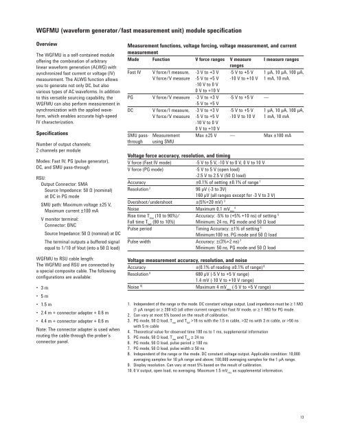
WGFMU (waveform generator/fast measurement unit) module specificationOverviewThe WGFMU is a self-contained moduleoffering the combination of arbitrarylinear waveform generation (ALWG) withsynchronized fast current or voltage (IV)measurement. The ALWG function allowsyou to generate not only DC, but alsovarious types of AC waveforms. In additionto this versatile sourcing capability, theWGFMU can also perform measurement insynchronization with the applied waveform,which enables accurate high-speedIV characterization.SpecificationsNumber of output channels:2 channels per moduleModes: Fast IV, PG (pulse generator),DC, and SMU pass-throughRSU:Output Connector: SMASource Impedance: 50 Ω (nominal)at DC in PG modeSMU path: Maximum voltage ±25 V,Maximum current ±100 mAV monitor terminal:Connector: BNCSource Impedance: 50 Ω (nominal) at DCThe terminal outputs a buffered signalequal to 1/10 of Vout (into a 50 Ω load)WGFMU to RSU cable length:The WGFMU and RSU are connected bya special composite cable. The followingconfigurations are available:• 3 m• 5 m• 1.5 m• 2.4 m + connector adapter + 0.6 m• 4.4 m + connector adapter + 0.6 mNote: The connector adapter is used whenrouting the cable through the prober’sconnector panel.Measurement functions, voltage forcing, voltage measurement, and currentmeasurementMode Function V force ranges V measure I measure rangesrangesFast IV V force/I measure,V force/V measure-3 V to +3 V-5 V to +5 V-5 V to +5 V-10 V to +10 V1 µA, 10 µA, 100 µA,1 mA, 10 mA.-10 V to 0 V0 V to +10 VPG V force/V measure -3 V to +3 V-5 V to +5 V-5 V to +5 V —DCSMU passthroughV force/I measure,V force/V measureMeasurementusing SMU-3 V to +3 V-5 V to +5 V-10 V to 0 V0 V to +10 V-5 V to +5 V-10 V to 10 V1 µA, 10 µA, 100 µA,1 mA, 10 mAMax ±25 V — Max ±100 mAVoltage force accuracy, resolution, and timingV force (Fast IV mode) -5 V to 5 V, -10 V to 0 V, 0 V to 10 VV force (PG mode)-5 V to 5 V (open load)-2.5 V to 2.5 V (50 Ω load)Accuracy ±0.1% of setting ±0.1% of range 1Resolution 2 96 μV (-3 to 3V)160 μV (all ranges except for -3 V to 3 V)Overshoot/undershoot ±(5%+20 mV) 34Noise Maximum 0.1 mV rmsRise time T rise(10 to 90%)/ Accuracy: -5% to (+5% +10 ns) of setting 5Fall time T fall(90 to 10%) Minimum: 24 ns, PG mode and 50 Ω loadPulse period Timing Accuracy: ±1% of setting 6Minimum:100 ns, PG mode and 50 Ω loadPulse width Accuracy: ±(3%+2 ns) 7Minimum: 50 ns, PG mode and 50 Ω loadVoltage measurement accuracy, resolution, and noiseAccuracy ±(0.1% of reading ±0.1% of range) 8Resolution 9680 μV (-5 V to +5 V range)1.4 mV (-10 V to +10 V range)Noise 10Maximum 4 mV rms(-5 V to +5 V range)1. Independent of the range or the mode. DC constant voltage output. Load impedance must be ≥ 1 MΩ(1 μA range) or ≥ 200 kΩ (all other current ranges) for Fast IV mode, or ≥ 1 MΩ for PG mode.2. Can vary at most 5% based on the result of calibration.3. PG mode, 50 Ω load, T riseand T fall>16 ns with the 1.5 m cable, >32 ns with 3 m cable, or >56 nswith 5 m cable4. Theoretical value for observed time 100 ns to 1 ms, supplemental information5. PG mode, 50 Ω load, T riseand T fall≥ 24 ns6. PG mode, 50 Ω load, pulse period ≥ 100 ns7. PG mode, 50 Ω load, pulse width ≥ 50 ns8. Independent of the range or the mode. DC constant voltage output. Applicable condition: 10,000averaging samples for 10 μA range and above; 100,000 averaging samples for the 1 μA range.9. Display resolution. Can vary at most 5% based on the result of calibration.10. 0 V output, open load, no averaging. Maximum 1.5 mV rmsas supplemental information.13


