IM8-40/IM8-32/IM8-24 Owner's Manual
IM8-40/IM8-32/IM8-24 Owner's Manual
IM8-40/IM8-32/IM8-24 Owner's Manual
- No tags were found...

Create successful ePaper yourself
Turn your PDF publications into a flip-book with our unique Google optimized e-Paper software.
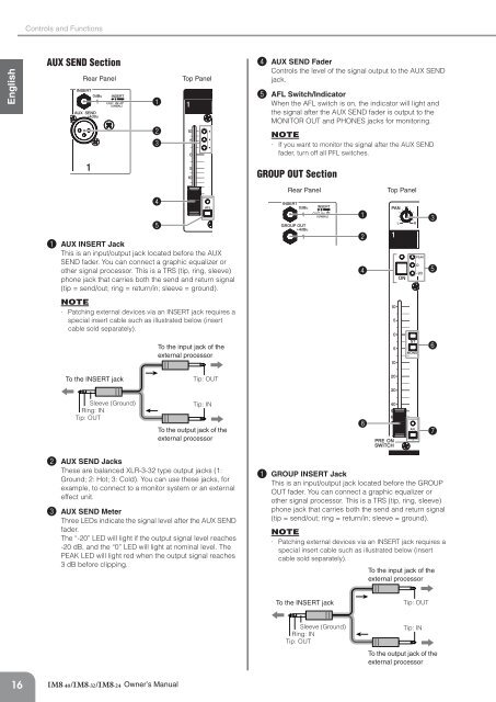
Controls and FunctionsEnglishAUX SEND SectionRear Panel123Top Panel4 AUX SEND FaderControls the level of the signal output to the AUX SENDjack.5 AFL Switch/IndicatorWhen the AFL switch is on, the indicator will light andthe signal after the AUX SEND fader is output to theMONITOR OUT and PHONES jacks for monitoring.NOTE· If you want to monitor the signal after the AUX SENDfader, turn off all PFL switches.GROUP OUT Section1 AUX INSERT JackThis is an input/output jack located before the AUXSEND fader. You can connect a graphic equalizer orother signal processor. This is a TRS (tip, ring, sleeve)phone jack that carries both the send and return signal(tip = send/out; ring = return/in; sleeve = ground).45Rear Panel1<strong>24</strong>Top Panel35NOTE· Patching external devices via an INSERT jack requires aspecial insert cable such as illustrated below (insertcable sold separately).To the input jack of theexternal processor6To the INSERT jackTip: OUTSleeve (Ground)Ring: INTip: OUTTip: INTo the output jack of theexternal processor872 AUX SEND JacksThese are balanced XLR-3-<strong>32</strong> type output jacks (1:Ground; 2: Hot; 3: Cold). You can use these jacks, forexample, to connect to a monitor system or an externaleffect unit.3 AUX SEND MeterThree LEDs indicate the signal level after the AUX SENDfader.The “-20” LED will light if the output signal level reaches-20 dB, and the “0” LED will light at nominal level. ThePEAK LED will light red when the output signal reaches3 dB before clipping.1 GROUP INSERT JackThis is an input/output jack located before the GROUPOUT fader. You can connect a graphic equalizer orother signal processor. This is a TRS (tip, ring, sleeve)phone jack that carries both the send and return signal(tip = send/out; ring = return/in; sleeve = ground).NOTE· Patching external devices via an INSERT jack requires aspecial insert cable such as illustrated below (insertcable sold separately).To the input jack of theexternal processorTo the INSERT jackTip: OUTSleeve (Ground)Ring: INTip: OUTTip: INTo the output jack of theexternal processor16Owner’s <strong>Manual</strong>