Continuous-Time Common-Mode Feedback for ... - ResearchGate
Continuous-Time Common-Mode Feedback for ... - ResearchGate
Continuous-Time Common-Mode Feedback for ... - ResearchGate

Create successful ePaper yourself
Turn your PDF publications into a flip-book with our unique Google optimized e-Paper software.
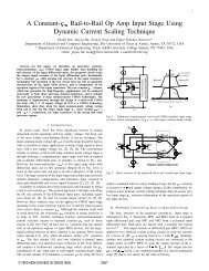
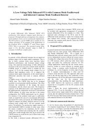
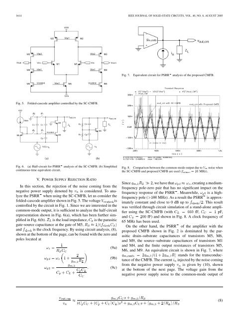
1614 IEEE JOURNAL OF SOLID-STATE CIRCUITS, VOL. 40, NO. 8, AUGUST 2005Fig. 7. Equivalent circuit <strong>for</strong> PSRR analysis of the proposed CMFB.Fig. 5.Folded-cascode amplifier controlled by the SC-CMFB.Fig. 6. (a) Half-circuit <strong>for</strong> PSRR analysis of the SC-CMFB. (b) Simplifiedcontinuous-time equivalent circuit.V. POWER SUPPLY REJECTION RATIOIn this section, the rejection of the noise coming from thenegative power supply denoted by is considered. To analyzethe PSRR when using the SC-CMFB, let us consider thefolded-cascode amplifier shown in Fig. 5. The voltage iscontrolled by the circuit in Fig. 1. Since we are interested in thecommon-mode output, it is sufficient to analyze the half-circuitrepresentation shown in Fig. 6(a), which has been further simplifiedin Fig. 6(b). is the load impedance, is the parasiticgate-source capacitance at the gate of M5,and is the clock frequency. By using circuit analysis, (8),shown at the bottom of the page, can be found with the zero andpoles located at(9a)(9b)(9c)Fig. 8. Comparison between the common-mode output due to V noise whenthe SC-CMFB and proposed CMFB are used (f =10MHz).Since , we have that , creating a mediumfrequencypole-zero pair that has no significant impact on thefrequency response of the PSRR . Meanwhile, is a highfrequencypole ( MHz). As a result the PSRR is approximatelyconstant and close to 0 dB up to . This resultwas verified through circuit simulation of a stand-alone amplifierusing the SC-CMFB (with fF, pF,and fF) and shown in Fig. 8. A clock frequency of65 MHz has been used.On the other hand, the PSRR of the amplifier with theproposed CMFB shown in Fig. 2 is dominated by the parasiticdrain–substrate capacitances of transistors M5, M6,and M9, the source–substrate capacitances of transistors M1and M4, and the finite output resistances of transistors M5,M6, and M9. An equivalent circuit is shown in Fig. 7, wherestands <strong>for</strong> the transconductanceof the CMFB. The current injected by the noise comingfrom the negative power supply is given by (10), shownat the bottom of the next page. The voltage gain from thenegative power supply noise to the common-mode output of(8)