
Create successful ePaper yourself
Turn your PDF publications into a flip-book with our unique Google optimized e-Paper software.
<strong>User</strong> <strong>Manual</strong>7.6.2 Image Recording .............................................................................................. 1127.6.3 Print .................................................................................................................. 1137.6.4 Move to Web Monitor ....................................................................................... 1137.6.5 Channel On/Off ................................................................................................ 1137.6.6 Recording Duration & Recording Size Check .................................................. 1137.6.7 Calendar Search .............................................................................................. 1147.6.8 Playback Toolbar .............................................................................................. 114Trouble Shooting ........................................................................ 114Compatible HDD List .................................................................. 117Compatible Media List ................................................................ 117Specification ............................................................................... 117Dimensions ................................................................................. 1226
<strong>User</strong> <strong>Manual</strong>Chapter 1. Safety Cautions1.1 Explaining the SymbolsWarningRefers to information users need to know in order to prevent serious injury ordeath. Before installationVerify the supplied voltage (AC100V~AC240V) before connecting to the power supply.Make sure the power supply is off before installation.Do not install in a very humid environment. Doing so may cause an electric shock or fire.Make sure ground line is connected to reduce electric shock risk. During operationDo not open the product cover except by qualified personnel or system installer. Opening theproduct cover may cause an electric shock.Do not plug multiple appliances into a single power outlet. Doing so may cause fire.Do not place dishes holding water or heavy objects on the product. Doing so may cause amalfunction.Do not use in areas where inflammable substances such as propane gas or gasoline or highamount of dust is present. Doing so may cause an explosion or fire.Do not touch the power line with a wet hand. Doing so may cause an electric shock.Do not insert a hand into the opening of the DVD. Doing so may cause an injury.Make sure conductive materials do not enter the cooling ventilator opening.Do not apply excessive force when pulling on the power cord. Damaging the cord may causean electric shock or fire.Improper replacement of the built-in battery by other types of batteries may cause explosion.The batter must be replaced by the same battery type. Also, expired batteries may causepollution and must be disposed of with care.Do not place the battery in fire or in extreme heat. Also, do not dissect or disassemble thebattery.Recharge the batteries for the remote controller. Dismantling and cleaningDo not dismantle, repair or modify the product deliberately. Doing so may cause a damage, anelectric shock or an injury.7
<strong>User</strong> <strong>Manual</strong>Do not use water, paint thinner or organic solvent for cleaning the product exterior. Doing somay cause a malfunction or an electric shock. Use a dry cloth to clean the exterior.CautionProvides information users need to know in order to prevent minorinjury or product damage. During installationFor adequate ventilation, install the product with at least 15cm of space between the coolerand the wall surface.To prevent falling, install the product on a flat area . Dropping the product may cause an injuryor a malfunction.Avoid areas exposed to direct exposure to sun light or excessive heat since they may causedeformation or a malfunction.If a camera is installed while the DVR is being recorded, image in another channel may bedisrupted. Starting the storage after the camera has been installed is recommended. During useMake sure the product is not exposed to concussions or shaking during usage or movement.Do not move, throw or expose to excessive physical concussion during usage.Installing additional unapproved hard disk drives may result in abnormal operation. Inquire atthe agency of purchase before installing additional hard disk drives.Product warranty will not cover malfunctions due to additional installation of unapproved harddisk drives.This product is a supplementary rather than primary means for preventing fire and theft. Ourcompany is not responsible for accidents or damage that may occur.<strong>Samsung</strong> Techwin recommends the installation of a UPS (Uninterrupted PowerSupply) with all its recording products.<strong>Samsung</strong> Techwin cares for the environment at all productmanufacturing stages, and is taking a number of steps to providecustomers with more environmentally friendly products. The Ecomark represents <strong>Samsung</strong> Techwin’s will to create environmentallyfriendly products, and indicates that the product satisfies the EURoHS Directive.FCC Compliance StatementNOTE : This equipment has been tested and found to comply with the limits for a Class A digitaldevice, pursuant to part 15 of the FCC Rules. These limits are designed to provide reasonable8
<strong>User</strong> <strong>Manual</strong>protection against harmful interference when the equipment is operated in a commercialenvironment. This equipment generates, uses, and can radiate radio frequency energy and, if notinstalled and used in accordance with the instruction manual, may cause harmful interference toradio communications. Operation of this equipment in a residential area is likely to cause harmfulinterference in which cause the user will be required to correct the interference at his own expense.Correct Disposal of This Product(Waste Electrical & Electronic Equipment)(Applicable in the European Union and other European countries with separatecollection systems.) This marking shown on the product or its literature, indicates that itshould not be disposed with other household wastes at the end of its working life. Toprevent possible harm to the environment or human health from uncontrolled wastedisposal, please separate this from other types of wastes and recycle it responsibly to promote thesustainable reuse of material resources. Household users should contact either the retailer wherethey purchased this product, or their local government office, for details of where and how they cantake this item for environmentally safe recycling. Business users should contact their supplier andcheck the terms and conditions of the purchase contract. This product should not be mixed withother commercial wastes for disposal.Correct Disposal of Batteries in this Product(Applicable in the European Union and other European countries withseparate battery return systems.)This marking on the battery, manual or packaging indicates that the batteries in thisproduct should not be disposed of with other household waste at the end of theirworking life. Where marked, the chemical symbols Hg, Cd or Pb indicate that thebattery contains mercury, cadmium or lead above the reference levels in ECDirective 2006/66. If batteries are not properly disposed of, these substances can cause harm tohuman health or the environment. To protect natural resources and to promote material reuse,please separate batteries from other types of waste and recycle them through your local, free batteryreturn system. The rechargeable battery incorporated in this product is not user replaceable.For information on its replacement, please contact your service provider.9
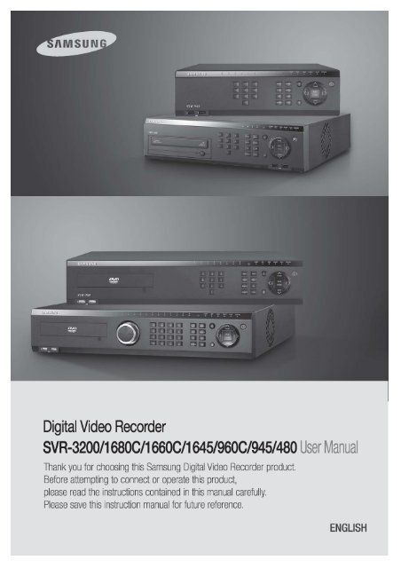
<strong>User</strong> <strong>Manual</strong>Chapter 2. SummaryThis unit is a digital video recording and playback device to record image and video inputfrom 32/16/9/4 channels to its built-in hard disk. The buttons on the front of the unit aswell as the mouse and GUI allow easy setup and operation.The <strong>Samsung</strong> <strong>SVR</strong> series of digital video recorders (DVRs) provide additional safety andsecurity to banks, apartment buildings and complexes, government offices as well asother public, private and commercial facilities. Recorded high-quality video and imagesare stored on hard disk for later retrieval or playback. Real time functionality deliversusers with the ability to simultaneously record multiple channels, playback video, andcopy video. A few of the more advanced user-conveniences include motion detection,Pan/Tilt/Zoom controls (PTZ), password protection, real time audio recording, event lists,and log files.2.1 FeaturesMonitoring ScreenThe monitoring screen supports vivid, high-definition live visual feed from each channel andprovides multiple screens. Real time MPEG-4 visual output (480 frames) Multiple split-screen monitoring modes<strong>SVR</strong>-<strong>3200</strong>/1680C/1660C/1645: Single, 4, 9, 10, 16<strong>SVR</strong>-960C/945: Single, 4, 9<strong>SVR</strong>-480 : Single, 4 Automatic Screen Switching (AUTO) Supports various monitor output modes<strong>SVR</strong>-<strong>3200</strong>: 4 Composite, 2 VGA<strong>SVR</strong>-1680C: 4 Composite, 1 VGA<strong>SVR</strong>-1660C/1645/960C/945/480: 2 Composite, 1 VGA Pan/Tilt, Digital Zoom, PIP (Picture-In-Picture), The PIP function will be availablewith a firmware upgrade in the future.Audio Recording10
<strong>User</strong> <strong>Manual</strong><strong>SVR</strong> series DVRs provide real time audio recording. Simultaneous recording of 16/9/4 channels of audio in real time<strong>SVR</strong>-<strong>3200</strong>/1680C/1600/1645 : Input - 16 channels (4 RCA in rear, 12 D-SUB),Output - 1 in rear, <strong>SVR</strong>-960C/945 : 9 channels (4 RCA in rear, 5 D-SUB),Output - 1 in rear, <strong>SVR</strong>-480 : 4 channels (4RCA), Output – 1 in rear Supports simultaneous recording and playbackVideo RecordingThe product is capable of storing visual image data as high resolution MPEG-4 video at upto 480 frames per second, as well as pre-emptively initiating recording sequences up to fiveseconds prior to an event. The COVERT feature (concealment of private visual data) helpsto protect privacy. High quality real time MPEG-4 recording Three screen-resolution levels for improved control over data sizes Multi-recording for manual and scheduled events Simultaneous recording/playback/backup/networking Easily accessible options for channel-specific resolution and motion detectionranges Per-second frame rates (up to 30 frames per channel) are user customizable<strong>SVR</strong>-<strong>3200</strong> Half D1 : NTSC (704x240) 960fps, PAL (704x288) 800fps<strong>SVR</strong>-1680C D1 : NTSC (704x480) 480fps, PAL (704x576) 400fps<strong>SVR</strong>-1660C/1645 CIF : NTSC (352x240) 480fps, PAL (352x288) 400fps<strong>SVR</strong>-960C/945 CIF : NTSC (352x240) 270fps, PAL (352x288) 225fps<strong>SVR</strong>-480 D1 : NTSC (704x480) 120fps, PAL (704x576) 100fps <strong>Manual</strong> and scheduled recording Video signal loss detection Event logs (sensors, D-I/O, video loss, motion detection, text) Each channel supports pre-emptive recording sequences up to 5 seconds prior toan actual eventSearch/Playback11
<strong>User</strong> <strong>Manual</strong>Various search and playback options are offered for the user’s convenience. Playback by time, date and channel Mouse interface increases data searchability Forward/backward search while playback is paused Playback by event log entry (sensor, video loss, motion detection and text) Remote controller and Jog/Shuttle further improve searching (The <strong>SVR</strong>-960C/945/480 models do not support Jog/Shuttle.) Full-frame playback (Available in <strong>SVR</strong>-<strong>3200</strong>/1680C/1660C only)Data StorageThe hard disk included with the product is for data storage. If desired, recorded data can bebacked up or stored to DVD-R, CD-R or a USB storage device. The built-in hard disk is provided as primary storage Multiple portable data storage media are supported: DVD-R, CD-R and USB※ Refer to the appendix on the back of the manual regarding compatible media types. Hard disk expansion device (external recording device): SVS-5E (optional) Externalhard disk expansion is supported with the SVS-5E (Available for purchaseseparately)12
<strong>User</strong> <strong>Manual</strong>NetworkingThe product supports LAN, xDSL and other networking capabilities. Combined with the PCinterface client, the core features of the device can be easily remotely controlled. E-mails can be sent via TCP/IP or DHCP upon an event trigger Remote live visual feed (single or 4 section split-screen) PC playback, storage, search and DVR control functions via Network Viewer Remote recording, search and playback scheduling Supports 10/100Mbps Ethernet/xDSL Multiple DVR connectionsMiscellaneous <strong>User</strong>-friendly GUI and mouse interface Simplified firmware upgrades through USB Visual data recording and backup to USB Supports PTZ control (SPEED DOME), Coax, PRESET Multilingual support: Korean, English, Italian, Spanish, Japanese Single remote controller to control 16 DVRs13
<strong>User</strong> <strong>Manual</strong>Chapter 3. Product Description3.1 Front Part3.1.1 <strong>SVR</strong>-<strong>3200</strong>No. Classification Function1DVD-Multi for For copying recorded video and images to DVD/CDcopyingoptical media.2 Channel LED Shows the data input and event operation status3 JOG/SHUTTLEJog can adjust setting values, control the STEP function,navigate through the menu, and adjust the playbackspeed and direction. Shuttle controls PTZ.4 Channel button Selects channel in live feed or playback5 AUTO Starts or stops user defined sequences.6 MULTI Changes split-screen sections for live video feeds orplayback.7 MENU Navigates into the Menu.8 SEARCH Starts Search mode.9 REC button Starts or stops manual recordingREC lampLit when recording.10HDD lampLit when HDD is working.NETWORK lamp Lit when network is connected.EVENT lamp Lit when an event is detected.14
<strong>User</strong> <strong>Manual</strong>COPY lamp Indicates copying operation.PLAY lampLit when copying.11 Power button Turns on or off the device.12 ESC button The Escape button navigates up the menu tree andcloses dialog windows.13 COPY Starts Copy mode.14 FUNC Starts Function mode.15 MONITOR Cycles through from Monitor 1 to 4.16 PTZ Starts or ends PTZ function.17USB ports for external devices (mouse, USB memoryUSB1, USB2stick).18 PLAY/ENTER Start playback or select an item on the menu.19 ◀/REW Navigates or selects in the menu, or for playback,changes the reverse playback speed.20 ▶/FWD Navigates or selects in the menu, or for playback,changes the forward playback speed.31 ▲/PAUSE Navigates or selects in the menu, or for playback,pauses live or recorded video.22▼/STOPNavigates or selects in the menu, or for playback, stopsplayback.15
<strong>User</strong> <strong>Manual</strong>3.1.2 <strong>SVR</strong>-1680C, <strong>SVR</strong>-1660C, <strong>SVR</strong>-1645No. Classification Function1DVD-Multi for For copying recorded video and images to DVD/CDcopyingoptical media.2 Channel LED Shows the data input and event operation status3 JOG/SHUTTLEJog can adjust setting values, control the STEP function,navigate through the menu, and adjust the playbackspeed and direction. Shuttle controls PTZ.4 Channel button Selects channel in live feed or playback5 AUTO Starts or stops user defined sequences.6 MULTI Changes split-screen sections for live video feeds orplayback.7 MENU Navigates into the Menu.8 SEARCH Starts Search mode.9 REC button Starts or stops manual recordingREC lampLit when recording.HDD lampLit when HDD is working.10NETWORK lamp Lit when network is connected.EVENT lamp Lit when an event is detected.COPY lamp Indicates copying operation.PLAY lamp Lit when copying.11 Power button Turns on or off the device.12 ESC button The Escape button navigates up the menu tree and16
<strong>User</strong> <strong>Manual</strong>closes dialog windows.13 COPY Starts Copy mode.14 FUNC Starts Function mode.15 MONITOR Cycles through from Monitor 1 to 4 : <strong>SVR</strong>-1680C,Switches from main and sub monitor : <strong>SVR</strong>-1660C,<strong>SVR</strong>-164516 PTZ Starts or ends PTZ function.17USB ports for external devices (mouse, USB memoryUSB1, USB2stick).18 PLAY/ENTER Start playback or select an item on the menu.19 ◀/REW Navigates or selects in the menu, or for playback,changes the reverse playback speed.20 ▶/FWD Navigates or selects in the menu, or for playback,changes the forward playback speed.31 ▲/PAUSE Navigates or selects in the menu, or for playback,pauses live or recorded video.22▼/STOPNavigates or selects in the menu, or for playback, stopsplayback.17
<strong>User</strong> <strong>Manual</strong>3.1.3 <strong>SVR</strong>-960CNo. Classification Function1DVD-Multi for For copying recorded video and images to DVD/CDcopyingoptical media.2 Channel LED Shows the data input and event operation status3 Channel button Selects channel in live feed or playback4 AUTO Starts or stops user defined sequences.5 MULTI Changes split-screen sections for live video feeds orplayback.6 MENU Navigates into the Menu.7 SEARCH Starts Search mode.8 REC button Starts or stops manual recordingREC lampLit when recording.HDD lampLit when HDD is working.9NETWORK lamp Lit when network is connected.EVENT lamp Lit when an event is detected.COPY lamp Indicates copying operation.PLAY lamp Lit when copying.10 Power button Turns on or off the device.11 ESC button The Escape button navigates up the menu tree andcloses dialog windows.12 COPY Starts Copy mode.13 FUNC Starts Function mode.18
<strong>User</strong> <strong>Manual</strong>14 MONITOR Switches from main and sub monitor15 PTZ Starts or ends PTZ function.16USB ports for external devices (mouse, USB memoryUSB1, USB2stick).17 PLAY/ENTER Start playback or select an item on the menu.18 ◀/REW Navigates or selects in the menu, or for playback,changes the reverse playback speed.19 ▶/FWD Navigates or selects in the menu, or for playback,changes the forward playback speed.20 ▲/PAUSE Navigates or selects in the menu, or for playback,pauses live or recorded video.21▼/STOPNavigates or selects in the menu, or for playback, stopsplayback.19
<strong>User</strong> <strong>Manual</strong>3.1.4 <strong>SVR</strong>-945No. Classification Function1 Channel LED Shows the data input and event operation status2 Channel button Selects channel in live feed or playback3 AUTO Starts or stops user defined sequences.4 MULTI Changes split-screen sections for live video feeds orplayback.5 MENU Navigates into the Menu.6 SEARCH Starts Search mode.7 REC button Starts or stops manual recordingREC lampLit when recording.HDD lampLit when HDD is working.8NETWORK lamp Lit when network is connected.EVENT lamp Lit when an event is detected.COPY lamp Indicates copying operation.PLAY lamp Lit when copying.9 Power button Turns on or off the device.10 ESC button The Escape button navigates up the menu tree andcloses dialog windows.11 COPY Starts Copy mode.12 FUNC Starts Function mode.13 MONITOR Switches from main and sub monitor20
<strong>User</strong> <strong>Manual</strong>14 PTZ Starts or ends PTZ function.15USB ports for external devices (mouse, USB memoryUSB1, USB2stick).16 PLAY/ENTER Start playback or select an item on the menu.17 ◀/REW Navigates or selects in the menu, or for playback,changes the reverse playback speed.18 ▶/FWD Navigates or selects in the menu, or for playback,changes the forward playback speed.19 ▲/PAUSE Navigates or selects in the menu, or for playback,pauses live or recorded video.20▼/STOPNavigates or selects in the menu, or for playback, stopsplayback.21
<strong>User</strong> <strong>Manual</strong>3.1.5 <strong>SVR</strong>-480No Classification Function1DVD-Multi for For copying recorded video and images to DVD/CD opticalcopyingmedia.2 Channel button Selects channel in live feed or playback3 Channel LED Shows the data input and event operation status4 AUTO Starts or stops user defined sequences.5 MULTI Changes split-screen sections for live video feeds orplayback.6 MENU Navigates into the Menu.7 SEARCH Starts Search mode.8 REC button Starts or stops manual recordingREC lamp Lit when recording.HDD lamp Lit when HDD is working.NETWORK Lit when network is connected.9 lampEVENT lamp Lit when an event is detected.COPY lamp Indicates copying operation.PLAY lamp Lit when copying.10 Power button Turns on or off the device.11 USB1, USB2 USB ports for external devices (mouse, USB memory stick).12 ESC button The Escape button navigates up the menu tree and closes22
<strong>User</strong> <strong>Manual</strong>dialog windows.13 COPY Starts Copy mode.14 FUNC Starts Function mode.15 MONITOR Switches from main and sub monitor16 PTZ Starts or ends PTZ function.17 PLAY/ENTER Start playback or select an item on the menu.18 ◀/REW Navigates or selects in the menu, or for playback, changesthe reverse playback speed.19 ▶/FWD Navigates or selects in the menu, or for playback, changesthe forward playback speed.20 ▲/PAUSE Navigates or selects in the menu, or for playback, pauseslive or recorded video.21▼/STOPNavigates or selects in the menu, or for playback, stopsplayback.23
<strong>User</strong> <strong>Manual</strong>3.2 Rear Part3.2.1 <strong>SVR</strong>-<strong>3200</strong>No. Input/OutputFunctionterminal name1 POWER IN Socket for AC 100V ~ AC 240V power cord.2 CH1 ~ 32 Connection terminal for camera BNC input.3 MONITOR 1 ~ 4 Connection terminal for monitor BNC output.4 AUDIO IN(RCA) RCA audio jack for RCA input.5 AUDIO OUT Audio jack for speaker output.6 GROUND Ground terminal between DVR and external device.7 ETHERNET Ethernet port for network connections (RJ-45).8 STORAGE External storage connection port (Function not supported in thecurrent version)9 eSATA Connection terminal for external eSATA HDD or HDD for backups.10 VGA OUTPUT 2 Output port for PC monitor.11 VGA OUTPUT 1 Output port for PC monitor.12 Serial Port (TerminalBlock)Connection terminal for expanded controller, speed dome camera,etc.RS-232C/485/42213 Serial Port (D-Sub) RS-232C D-SUB connector.14 RELAY OUT Connection terminal for relay output.24
<strong>User</strong> <strong>Manual</strong>15 SENSOR IN Connection terminal for sensor input.16 AUDIO IN(D-SUB) Connection terminal for audio output D-SUB.17 D-I/O Connection terminal for DIGITAL IN/OUT.3.2.2 <strong>SVR</strong>-1680C, <strong>SVR</strong>-1660C, <strong>SVR</strong>-1645No. Input/OutputFunctionterminal name1 POWER IN Socket for AC 100V ~ AC 240V power cord.2 CH1~16 Connection terminal for camera BNC input.3 LOOP OUT Connection terminal for camera BNC output (loop).4 MONITOR 1 ~ 2 Connection terminal for monitor BNC output.5 AUDIO IN(RCA) RCA audio jack for RCA input.6 AUDIO OUT Audio jack for speaker output.7 GROUND Ground terminal between DVR and external device.8 ETHERNET Ethernet port for network connections (RJ-45).9 STORAGE External storage connection port (Function not supported inthe current version)10 eSATA Connection terminal for external eSATA HDD or HDD forbackups.11 VGA OUTPUT Output port for PC monitor.12 Serial Port (TerminalBlock) RS-232C/485/422Connection terminal for expanded controller, speed domecamera, etc.13 Serial Port (D-Sub) RS-232C D-SUB connector.25
<strong>User</strong> <strong>Manual</strong>14 RELAY OUT Connection terminal for relay output.15 SENSOR IN Connection terminal for sensor input.16 AUDIO IN(D-SUB) Connection terminal for audio output D-SUB.17 D-I/O Connection terminal for DIGITAL IN/OUT.3.2.3 <strong>SVR</strong>-960CNo. Input/OutputFunctionterminal name1 POWER IN Socket for AC 100V ~ AC 240V power cord.2 GROUND Ground terminal between DVR and external device.3 CH1~9 Connection terminal for camera BNC input.4 LOOP OUT Connection terminal for camera BNC output (loop).5 MONITOR 1 ~ 2 Connection terminal for monitor BNC output.6 AUDIO IN(RCA) RCA audio jack for RCA input.7 AUDIO OUT Audio jack for speaker output.8 ETHERNET Ethernet port for network connections (RJ-45).9 eSATA Connection terminal for external eSATA HDD or HDD for backups.10 VGA OUTPUT Output port for PC monitor.11 Serial Port (D-Sub) RS-232C D-SUB connector.12 Serial Port (TerminalBlock)Connection terminal for expanded controller, speed dome camera,etc.RS-232C/485/42213 RELAY OUT Connection terminal for relay output.26
<strong>User</strong> <strong>Manual</strong>14 SENSOR IN Connection terminal for sensor input.15 AUDIO IN(D-SUB) Connection terminal for audio output D-SUB.16 D-I/O Connection terminal for DIGITAL IN/OUT.3.2.4 <strong>SVR</strong>-945No. Input/OutputFunctionterminal name1 CH1~9 Connection terminal for camera BNC input.2 LOOP OUT Connection terminal for camera BNC output (loop).3 MONITOR 1 ~ 2 Connection terminal for monitor BNC output.4 AUDIO IN(RCA) RCA audio jack for RCA input.5 AUDIO OUT Audio jack for speaker output.6 ETHERNET Ethernet port for network connections (RJ-45).7 eSATA Connection terminal for external eSATA HDD or HDD forbackups.8 VGA OUTPUT Output port for PC monitor.9 Serial Port (D-Sub) RS-232C D-SUB connector.10 Serial Port (TerminalBlock) RS-232C/485/422Connection terminal for expanded controller, speed domecamera, etc.11 RELAY OUT Connection terminal for relay output.12 AUDIO IN(D-SUB) Connection terminal for audio output D-SUB.13 SENSOR IN Connection terminal for sensor input.27
<strong>User</strong> <strong>Manual</strong>14 D-I/O Connection terminal for DIGITAL IN/OUT.15 GROUND Ground terminal between DVR and external device.16 POWER IN Socket for AC 100V ~ AC 240V power cord.3.2.5 <strong>SVR</strong>-480No. Input/OutputFunctionterminal name1 GROUND Ground terminal between DVR and external device.2 CH1~4 Connection terminal for camera BNC input.3 LOOP OUT Connection terminal for camera BNC output (loop).4 MONITOR 1 ~ 2 Connection terminal for monitor BNC output.5 AUDIO IN(RCA) RCA audio jack for RCA input.6 AUDIO OUT Audio jack for speaker output.7 ETHERNET Ethernet port for network connections (RJ-45).8 eSATA Connection terminal for external eSATA HDD or HDD fobackups.9 Serial Port (D-Sub) RS-232C D-SUB connector.10 VGA OUTPUT Output port for PC monitor.11 Serial Port (Terminal Block)RS-485/422Connection terminal for expanded controller, speeddome camera, etc.12 RELAY OUT Connection terminal for relay output.13 SENSOR IN Connection terminal for sensor input.14 POWER IN Socket for AC 100V ~ AC 240V power cord.28
<strong>User</strong> <strong>Manual</strong>Refer to detailed description for installation & use from “Install <strong>Manual</strong>”.3.3 OSD MENU structureThe menu structure is as shown below. For detailed instructions for configuration, please refer toChapter 4, 5 and 6.29
<strong>User</strong> <strong>Manual</strong>3.4 Function MenuThe function menu allows the users to access any and all functions and operations of the product with themouse. To execute a particular function, left-click the icon. Also, all functions listed in the function menucan be executed in full-screen mode. The function menu structure is as shown below.Live Function MenuPlayback Function Menu3.5 Factory settingTo restore the unit back to its factory settings, go to System > System > Restore Factory Setting.A pop-up window saying, "Warning : The system will be reset. Continue with restoring factorydefault?" will appear. Select "Yes" and press Enter to restore the factory default settings.30
<strong>User</strong> <strong>Manual</strong>Factory DefaultQuick SetupRecord Mode ¡¡ <strong>Manual</strong> & EventScheduleNot SetEvent CheckAlwaysLanguageEnglishTime ¡¡ UTC 00:00 DublinNoMM/DD/YYYYCurrent timeDisplay SetupChannel Channel NumberCh1Display Title Cam 1StatusEnableColorColorAGCEnableBrightness 0Contrast 0Monitor Monitor Number Main Monitor (Monitor 1)Covert ChannelDeselect AllSequencingNumber 1 is set to Channel 1 andNumber 2 is set to Channel 2 in order.Dwell Time5 sec.Multi Display 4E Channels 1, 3, 5 and 7VGA Mode800x600@56HzOn Screen DisplaySelect AllRecord SetupRecord Record Mode Schedule & EventSchedule Not Set AllEvent DurationBefore: 1 sec., After: 1 sec.Repeat RecordOnModeWarning Level ¡¡ 45%Record DataOffRetention31
<strong>User</strong> <strong>Manual</strong>PlaybackOnDeinterlaceAudio >>Audio Ch1ChannelAudio OffRecordingAudio Gain 0Sync Video Ch1ChannelAudio Mix Mix OnProgram A~Z ¡¡ CIF, 0fps, Q1Event SetupEvent Event Check AlwaysNormalEventEvent Screen /Dwell Monitor 1 OfftimeEvent Source Deselect AllEvent Action Relay 1Action 10 sec.DurationNormal Event Deselect AllSourceSystem EventSourceDeselect AllMDAll ChannelMD Sensitivity 2AreaSet AllSensor All Sensor N.OText >>Recording OffSync Text Ch1WithDevice <strong>Manual</strong>Seek Header OffHeader 1 header1Header 2 header2Delimiter 0D0A32
<strong>User</strong> <strong>Manual</strong>Timeout(ms) 1000Lines 20Preset Channel Number Ch1PresetNot SetD-I/O D-I/O OutputOutput TypeSensorNetworkNetwork Type EthernetDHCPOffIP addrDefault IPNet MaskDefault NMGatewayDefault GWDNS1 0.0.0.0Additional DNS 0.0.0.0Port 4000BandWidth0Limit(Mbps)xDSL <strong>User</strong> ID ¡¡ guestPassword *****StatusxDSL not connected.Port 4000Bandwidth Limit0.0(Mbps)DDNS Interval OffServerwww.samsungipolis.comIDNonePasswordNoneStatusNot RegisteredNTP Sync With NTP OffNTP ModeClientNTP Server Loc. ¡¡ PublicNTP Local Server IP 0.0.0.0Interval1 (hour)Remote Remote Keyboard ID 1Remote Controller All33
<strong>User</strong> <strong>Manual</strong>IDRemoteEnableConfiguration SetupRemote RelayEnableSerial Com1, >>PTZ Ch1, >>System SetupSystem Language EnglishKey BuzzerOnDefault >>Load/SaveLoad, >>ConfigurationFirmware Update >>DVR AliasDVR0System Log >>Time >>I-Frame IntervalAutoDisk Disk Manager >>Disk Status >>Security Change P/W Default valueMenuCheck X, Admin and <strong>User</strong>: OPTZCheck X, Admin and <strong>User</strong>: ORelay OffCheck X, Admin and <strong>User</strong>: OPlaybackCheck X, Admin and <strong>User</strong>: OPower OffCheck X, Admin and <strong>User</strong>: OPower OnCheck X, Admin and <strong>User</strong>: OCopyCheck X, Admin and <strong>User</strong>: ON/MICCheck None, Admin and <strong>User</strong>: OExitExit Save >>Do not save >>34
<strong>User</strong> <strong>Manual</strong>Record ProgramModel <strong>SVR</strong>-1660C/1645 <strong>SVR</strong>-960C/945Mode Normal Event Normal EventRes Fps Q Res Fps Q Res Fps Q Res Fps QA D1 7 Q5 D1 7 Q5 D1 7 Q5 D1 7 Q5B D1 5 Q5 D1 7 Q5 D1 5 Q5 D1 7 Q5C D1 5 Q4 D1 7 Q5 D1 5 Q4 D1 7 Q5D D1 3 Q5 D1 5 Q5 D1 3 Q5 D1 5 Q5E D1 5 Q4 D1 7 Q5 D1 5 Q4 D1 7 Q5F D1 3 Q4 D1 5 Q4 D1 3 Q4 D1 5 Q4G D1 1 Q4 D1 3 Q4 D1 1 Q4 D1 3 Q4H D1 0 Q4 D1 7 Q5 D1 0 Q4 D1 7 Q5I Half 10 Q5 Half 15 Q5 Half 10 Q5 Half 15 Q5J Half 5 Q5 Half 20 Q5 Half 5 Q5 Half 20 Q5K Half 3 Q5 Half 10 Q5 Half 3 Q5 Half 10 Q5L Half 10 Q4 Half 20 Q5 Half 10 Q4 Half 20 Q5ProgramM Half 10 Q4 Half 15 Q5 Half 10 Q4 Half 15 Q5N Half 5 Q4 Half 10 Q5 Half 5 Q4 Half 10 Q5O Half 5 Q4 Half 10 Q4 Half 5 Q4 Half 10 Q4P Half 3 Q4 Half 5 Q4 Half 3 Q4 Half 5 Q4Q Half 1 Q4 Half 3 Q4 Half 1 Q4 Half 3 Q4R Half 0 Q4 Half 7 Q5 Half 0 Q4 Half 7 Q5S CIF 30 Q5 CIF 30 Q5 CIF 30 Q5 CIF 30 Q5T CIF 20 Q5 CIF 30 Q5 CIF 20 Q5 CIF 30 Q5U CIF 20 Q4 CIF 20 Q5 CIF 20 Q4 CIF 20 Q5V CIF 10 Q4 CIF 15 Q4 CIF 10 Q4 CIF 15 Q4W CIF 7 Q3 CIF 25 Q5 CIF 7 Q3 CIF 25 Q5X CIF 4 Q3 CIF 10 Q4 CIF 4 Q3 CIF 10 Q4Y CIF 1 Q4 CIF 3 Q4 CIF 1 Q4 CIF 3 Q4Z CIF 0 Q4 CIF 7 Q5 CIF 0 Q4 CIF 7 Q5Model <strong>SVR</strong>-1680C <strong>SVR</strong>-<strong>3200</strong>Mode Normal Event Normal EventRes Fps Q Res Fps Q Res Fps Q Res Fps QA D1 30 Q5 D1 30 Q5 D1 15 Q5 D1 15 Q535
<strong>User</strong> <strong>Manual</strong>menu. To stop this feature, press thebutton again or click Auto to toggle it in the Functionmenu.4.4.1 Default System Mode- Use the button to automatically convert the set channels.- Press the [MENU] button to set the dwell time. Alternately, click the button on theFunction menu.- Go to "Display Setup" on the OSD menu.- Go to the "Monitor" submenu under "Display Setup" and press the [Enter] button or leftclick.- Select "Dwell Time" and set a value between 1 and 60 seconds. When this is set to Off,auto sequencing will not work.- Selecting “Auto Sequencing” brings up an option to select channels or split screens forthe sequencing order, as shown in the picture below.38
<strong>User</strong> <strong>Manual</strong>- Auto sequencing mode can be enabled by pressing the [AUTO] button in all split modes.- To exit auto sequencing mode, press the [AUTO] button once again.1. Up to 16 user modes can be defined.2. In the image above, 6 sequences are defined with single screen (1) fullscreen (16DIV) 4 channel split-screen (4A) single screen (5) single screen(6) 9 channel split-screen (9A) all being displayed in sequence.The <strong>SVR</strong>-960C/945 support 9, <strong>SVR</strong>-480 supports 4 channel split-screen.4.4 Event ScreenYou can set an event screen to automatically pop up.- The Event Screen can be set for each monitor.39
<strong>User</strong> <strong>Manual</strong>- To set the dwell time for each event popup, select a monitor and set the dwell time for themonitor.- You can select events to pop up at Event Source. 3 types of event are available at EventSource: Sensor, Motion Detection, and Text.- When events occur in several channels simultaneously, the screen automatically splitsinto that number of channels. For example, if events occur in 3 channels, event imagesare displayed on the 4 channel split-screen. To return to the previous screen, press one ofthe channel buttons.1. If Event Screen is set to Off, event popups will not work.2. If Event Screen is set to On, the popup image remains displayed until abutton is pressed. To return to the previous screen, press any button.4.5 Zoom In- To zoom in on an image, press the [FUNC] button in single display full screen mode,select thebutton, select the + button, and press the [Enter] button or left-click.- When the button is selected, the default location is the center of the screen. When animage is zoomed in on, it can be moved 18 levels horizontally and 12 levels vertically.- Use the navigation keys to move the image.- To return to the previous screen, select the – button and then press the [Enter] button orleft-click.4.6 Live Video Pause- You can pause a live video feed.- Press the [PAUSE] button to pause a live video, and press the button again to resumethe live feed.40
<strong>User</strong> <strong>Manual</strong>4.7 PTZ ControlYou can control PTZ while watching a video in real time byconnecting the PTZ controller with the DVR and setting theprotocol from the "Serial" menu.You can either press the PTZ button on the front or press the[Func] button to execute PTZ.To control PTZ operation, first select a channel. The selectedchannel will be outlined in blue.Available PTZ and keyboard models are as shown below.ModelSDZ160/330, <strong>Samsung</strong> SPDKeyboard SCC3000, <strong>Samsung</strong> SRX-100BBOSCH AutoDome, TC8560X-4PELCO (P), PELCO (D)Honeywell 755/655, HRX-2000, ScanDome2Sony EVI-D3xVT VPT-4xAD SpeedDomeSungJin SJ372R1'<strong>Samsung</strong> SCC641Panasonic WV-CS850LG GAC-PT2Keyboard KBD300A, WGI SPD1800/2600Merit-Lilin FastDomeElmo PTC200CCanon VC-C4HTC-230SRVisionElbexVIDOVICONHuntORX-1000Fine CRR-1600MakerSAMSUNG TECHWINBOSCHPELCOHONEYWELLSONYVTADSUNGJINSAMSUNG ELECTRONICSPANASONICLGWEBGATE Inc.MERITELMOCANOND-MAXRVISIONELBEXVIDOVICONHUNTSYSMANIALIVEI41
<strong>User</strong> <strong>Manual</strong>TokinaKodicom KRENuvicoTOKINAKODICOMNUVICO- Press a channel button.- Press the [PTZ] button on the front or click the button on the Function menu.- The PTZ menu (Pan/Tilt, Zoom/Focus, Load Preset, Save Preset) will appear.- Select the desired menu item and then press the [Enter] button or click.4.7.1 Pan/TiltThis menu item is used for real-time Pan and Tilt monitoring.- Select Pan/Tilt in PTZ mode.- To use pan the camera, press the left or right arrow key on the front or click on the left orright of the screen. To tilt the camera, press the up or down arrow key on the front or clickon the top or bottom of the screen.4.7.2 Zoom/FocusThis menu item is for real-time Zoom and Focus monitoring.- Select Zoom/Focus in PTZ mode.- Use the navigation keys on the front or the mouse wheel to use Zoom and Focus.4.7.3 Load PresetThis menu item is used to go to a preset location in the real-time monitoring mode.- Use the up or down arrow key or the mouse wheel to select a preset number.- Select Load and then press the [Enter] button or click.4.7.4 Save PresetThis menu item is for setting a new preset location in the real-time monitoring mode.- Use the Pan/Tilt and Zoom/Focus menu items to adjust the camera position.- Use the up or down arrow key or the mouse wheel to select a preset number.- Select Save and then press the [Enter] button or click.4.7.5 Auxiliary OnThis is used for special functions of a PTZ device in real-time monitoring mode.- Use the up or down arrow key or the mouse wheel to set an Aux number.- Select On and then press the [Enter] button or click.- Up to 16 Aux numbers can be set.42
<strong>User</strong> <strong>Manual</strong>4.7.6 Auxiliary OffThis is to stop special functions of a PTZ device.- Use the up or down arrow key or the mouse wheel to set an Aux number.- Select Off and then press the [Enter] button or click.4.7.7 MenuThis is used to enter the console menu of the connected PTZ device. The console menu can beset with the navigation keys and the [Enter] button on the front.After settings are done, press the [ESC] button or the [PTZ] button on the front to exit theconsole menu (available only with the <strong>Samsung</strong> SPD protocol).43
<strong>User</strong> <strong>Manual</strong>Chapter 5. Playback5.1 Playback Mode5.1.1 Playback on Default Display (16/9/4 channel split-screen)- Press the [PLAY] button or click the button on the Function menu in monitoring mode.- Press the [PLAY] button or the [FWD] button to play a video at the default 1x speed.- Press the [REW] button to play a video in reverse at the default 1x speed.Press the [Play] button in monitor split mode to play videos from 16/9/4 channels.5.1.2 PlaybackPLAY: Play a video at 1x speed. When using a mouse, click thebutton in the Function menu.Pressing the [PLAY] button in monitor mode always plays multiplevideos. Also, pressing the [PLAY] button plays recorded videos fromthe last playback timestamp.PAUSE: Pause video playback. When using a mouse, click the buttonin the Function menu.STOP: Stop video playback. When using a mouse, click the button inthe Function menu.FWD: Each press of this button changes the playback speed (in the orderof x1, x2, x4, x8, x16, x32, x64, x1/2, x1, x2 and x4). Pressing the[FWD] button while viewing a live feed plays the video recorded 1minute before the current live time. Pressing thebutton on theFunction menu also changes the playback speed.REW: Each press of this button changes the reverse playback speed (in theorder of x1, x2, x4, x8, x16, x32, x64, x1/2, x1, x2 and x4).Pressing the [REW] button while viewing a live feed plays the video inreverse from the last recorded frame. Pressing thebutton on theFunction menu also changes the playback speed.44
<strong>User</strong> <strong>Manual</strong>STEP FORWARDSTEP REWIND1/2 REWIND: Pressing the [FWD] button while paused plays the video frame byframe. Press the [PLAY] button to return to normal playback.: Pressing the [REW] button while paused plays the video frame byframe in reverse. Press the [PLAY] button to return to normal playback.: Press the button on the Function menu to play the video at 1/2xspeed.1/2 FORWARD: Press the button on the Function menu to play the video inreverse at 1/2x speed.5.2 Search ModeThis menu item is used to search by time or log to play data at a specific time.Search mode includes Time, Calendar, Event and Thumbnail.To go into search mode, press the [Search] button on the front or click the [Search] button onthe Function menu.5.2.1 Time SearchEnter a desired date and time and select Search to go to the video at the specified date andtime.Start-REC TimeEnd-REC TimeSearch Time: Displays the date and time when the recording started.: Displays the date and time of the latest recording.: Select desired date and time between the recording start time and45
<strong>User</strong> <strong>Manual</strong>Search Buttonthe end time.: Search the video for the specified date and time.5.2.2 Calendar SearchYou can search videos more easily with the calendar.The following pictures are status screens that are selected with year, date, and time. For the <strong>SVR</strong>-<strong>3200</strong>, Monitor 1 displays the recording status from channel 1 to 16 while Monitor 2displays from channel 17 to 32.Clicking on the hourly recording section displays the minute status. YearMonthDateTimeMinute: Select a year. You can use the mouse wheel to change the year.: Select a month. You can use the mouse wheel to change the month.: Go to the calendar, select the desired date and press the [Enter]button. You can use the mouse wheel to search by time.: Select a time period and press the [Enter] button to start playback.When using a mouse, select the time and use the mouse wheel to playthe video at the specified time.: Displays saved video data by minute. To play, select a minute, andthen press Enter. When using the mouse, select a minute, and thenuse the mouse wheel to play the video.5.2.3 Event SearchYou can specify a time period and search all channels, some channels, all events, motion46
<strong>User</strong> <strong>Manual</strong>detection or sensors. Use the up or down arrow key on the front to change the date and time.Alternately, select an item you want to change and use the mouse wheel to change it. Thesearch results are displayed in a separate list in the event search result window. Select an itemin the search list and press the [Enter] button or use the mouse wheel to go to the specified dateand time and start playback.Start-REC TimeEnd-REC TimeSearch StartTimeSearch End TimeEvent ChannelEvent Type: Display the date and time when the recording started.: Display the date and time of the latest recording.: Enter a start date and time to start the search from. Use thenavigation buttons to go to an item, press the [Enter] button and usethe up or down arrow key to change the value. When using mouse,click an item and use the mouse wheel to change the value.: Enter an end date and time to search until. Use the navigationbuttons to go to an item, press the [Enter] button and use the up ordown arrow key to change the value. When using a mouse, click anitem and use the mouse wheel to change the value.: Select a channel.For the <strong>SVR</strong>-<strong>3200</strong>, Ch1 ~ Ch32 are available.For the <strong>SVR</strong>-1680C/1660C/1645, Ch1 ~ Ch16 are available.For the <strong>SVR</strong>-960C/945, Ch1 ~ Ch9 are available.For the <strong>SVR</strong>-480 Ch1~Ch4 are available.: Select an event type.You can select all events, motion detection, video loss or text.5.2.4 Thumbnail SearchUse the up or down arrow key on the front or the mouse wheel to a specify time and search aspecific channel at regular intervals. The search results are displayed in thumbnails. Select athumbnail to go to the specified date and time and start playback.47
<strong>User</strong> <strong>Manual</strong>ChannelStart TimeIntervalView VideoSelect Video: Select a channel. Use the up or down arrow key on the front or themouse wheel to change the value.: Enter a start date and time to start the search from. Use the left orright arrow key to go to an item, press the [Enter] button and use theup or down arrow key or the mouse wheel to change the value.: Search in a specific interval and display the result. Use the up ordown arrow key or the mouse wheel to change the value.: Press the [Search] button to display 16 videos in the specified intervalbased on the start time. Press the [Func] button or use the mousewheel to return to the search window.: Click a video thumbnail and play it from the specified time. Pressthe [Enter] button or click to play the video.Changing the I-frame duration may produce results different from your expectationfrom Thumbnail Search.5.3 CopyThis menu item is used to copy a recorded video. There are three types of copy: CD/DVD, RE4and AVI. To use the Copy function, you must change your permissions in the Security settings.For more information about changing permissions, please refer to section 6.9.3 on Security.Tocopy, press the [COPY] button on the front or click thebutton on the Function menu.5.3.1 CD/DVDThe CD/DVD type uses a CD or DVD to copy a video and detects the CD or DVD automatically.48
<strong>User</strong> <strong>Manual</strong>The <strong>SVR</strong>-945 is not equipped with a DVD device so you must connect the unitwith an external backup device. Connect an external backup device to the USBor eSATA port, execute copy and select CD/DVD. On the media list, a CD/DVD devicewhose type is [Ext] is displayed. Select the device and make a copy in the same way asother models.TypeChannelFromToSelect DiskStartFAT32 Format: Select CD/DVD. Use the up or down arrow key on the front or themouse wheel to select it. Press the [Enter] button and use the up ordown arrow key on the front or the mouse wheel to change the value.: You can select some or all of the 16 channels. Select the channelfield and press the [Enter] button or use the mouse wheel to select achannel.: Enter the start date and time for copying. Use the up or down arrowkey or the mouse wheel to set the value.: Enter the final date and time for copying. Use the up or down arrowkey or the mouse wheel to set the value.: Select the media to copy. Select the Select Disk field and press the[Enter] button to select the media.: Start copying. Move to the [Start] button and press the [Enter] buttonor left-click.: Format a USB disk or HDD in FAT32.Do not use this for CD/DVD copying. When using media, you need toformat it first. Select the [FAT32 Format] button and press the [Enter]button or left-click.49
<strong>User</strong> <strong>Manual</strong>For more information on support media, refer to the table below.DVD-R MakerMitsubishi (16x recommended)TDK (16x recommended)Imation (16x recommended)Sony (16x recommended)CD-R MakerMitsubishi (16x recommended)TDK (16x recommended)Imation (16x recommended)Sony (16x recommended)5.3.2 RE4You can back up videos using HDD or USB storage. You can play them using the mini player ornetwork manager. Select the channel field and use the [Enter] button or the mouse wheel toopen the channel list as shown below.[<strong>SVR</strong>-<strong>3200</strong>] [<strong>SVR</strong>-1680C/1660C/1645] [<strong>SVR</strong>-960C/945] [<strong>SVR</strong>-480]TypeChannelSelect ChannelFromToSelect Disk: Select RE4. Use the up or down arrow key or the mouse wheel toselect it.: Select the channel field and press the [Enter] button or use themouse wheel to pop up the channel list.: You can select some or all of the channels. Select a channel on thechannel list and press the [Enter] button or left-click.: Enter a start date and time for copying. Use the up or down arrow keyor the mouse wheel to set a value.: Enter the final date and time for copying. Use the up or down arrowkey or the mouse wheel to set a value.: Select a media to copy. Select the Select Disk field and press the50
<strong>User</strong> <strong>Manual</strong>StartFAT32 Format[Enter] button or click to select a media.: Start copying. Move to the [Start] button and press the [Enter] buttonor left-click.: Format unformatted USB storage devices or HDDs in FAT32 beforecopying. Select the [FAT32 Format] button and press the [Enter] buttonor left-click.A backup file that is not 100% complete cannot play on a PC properly.5.3.3 AVIThis type is used to copy a part of a selected channel using USB or HDD storage.TypeChannelFromDurationSelect Disk: Select AVI. Use the up or down arrow key or the mouse wheel to selectit.: Select a channel. Use the up or down arrow key or the mouse wheel toselect it.: Enter the start date and time for copying. Use the left or right arrow keyto move between the items and use the up or down arrow key to changethe time and date. When using a mouse, left-click an item and use thewheel to change the value.: Specify the duration for copying. Make a copy only for the specifiedduration. Use the up or down arrow key or the mouse wheel to specify it.: Select a media to copy. Select the Select Disk field and press the51
<strong>User</strong> <strong>Manual</strong>StartFAT32 Format[Enter] button or click to select media.: Start copying. Move to the [Start] button and press the [Enter] button orleft-click.: Format unformatted USB storage devices and HDDs in FAT32 beforecopying. Select the [FAT32 Format] button and press the [Enter] buttonor left-click.If the copied file does not play on a PC, install the unified codec pack.52
<strong>User</strong> <strong>Manual</strong>Chapter 6. Setup6.1 Record SetupThere are 4 DVR recording modes. Their relationship is as shown in the image below, whichbriefly describes recording modes.For more information on recording, refer to the following sections.RecordingEvent Recording Schedule Recording <strong>Manual</strong> RecordingEmergency Recording6.2 Time SetupYou need to set the system time before setting recording.Setting the time based on your location is very important for the protection of recorded data. It is53
<strong>User</strong> <strong>Manual</strong>not recommended to change the time while recording.The factory default time zone is UTC 00:00 Dublin.6.2.1 How to Set TimeIf you change the time when recording is already in progress, the time is alsochanged for existing recorded videos. It is recommended to back up criticalvideo data before changing the time.- Press the [MENU] button on the front or the button on the Function menu.- Go to the "Quick Setup" menu.- Select "Time" from "Quick Setup". Use the [Enter] button or the mouse wheel to select it.- If you press the buttons in the proper order, the image in 6.2 Time Setup appears.- Use the navigation keys or the mouse to move to each submenu and press the [Enter]button or click.Time ZoneUse the left or right arrow key on the front or the mouse wheel to select your time zone. Eachpress of the arrow keys changes the time zone. (To go to the previous menu, press the [ESC]button on the front or right-click. This is the same for all OSD menus.)Daylight Saving(1) When selecting a Daylight Saving Time zone, Daylight Saving automatically changes to On,and is Off for other time zones.(2) To customize the start and end time of DST, use the [◀/▶] buttons and change DaylightSaving to Custom.(3) Changing Daylight Saving to Custom displays the Custom DST Setup options.54
<strong>User</strong> <strong>Manual</strong>Upon clicking on Custom DST Setup, two setup methods display.The first is for selecting a month and date to define the start and end times of DST.The second is for selecting a month, week, and day to define the start and end times of DST.For more information on NTP, refer to "NTP" of Network Setup.Date FormatSelect the date format. Use the left or right arrow key or the mouse wheel to select"MM/DD/YYYY", "YYYY/MM/DD" or "DD/MM/YYYY".TimeUse the left or right arrow key to move between year, month, date and time. Use the up or downarrow key or the mouse wheel to set each item.ApplyYou must press the [Apply] button to save the Date/Time values. Then, the dialog box belowappears.55
<strong>User</strong> <strong>Manual</strong>Setups other than "Date/Time" setup are automatically recorded if the menus arecompletely closed, but "Date/Time" setup is not automatically recorded becauseit may damage the HDD recording file system. Be sure to press the [Apply]button to apply changes.6.3 Camera SetupThis menu is used to set the conditions of each camera connected to the unit.You can use the camera setup menu to adjust [Title], [Status], [Color], [AGC], [Brightness],[Contrast] for each of the connected cameras. The set values apply to monitoring and search inthe same way.For more information on each menu item, refer to the following sections.NTSC and PAL cameras cannot be used for the unit at the same time. Forexample, you cannot connect NTSC cameras to 1CH to 5CH while connectingPAL cameras to 6CH to 16CH. Also, when replacing NTSC cameras with PALcameras, you must reboot (power on/off) the unit after connecting the PALcameras for proper recognition.The set values apply to monitoring and search in the same way.56
<strong>User</strong> <strong>Manual</strong>6.3.1 How to Set a CameraPress the [MENU] button and use the navigation keys or the mouse wheel to select a desiredchannel from the "Channel" menu under the "Display" menu of Display Setup.TitleSpecify the camera name.Press the [Enter] button or click to open the character input menu.When inputting a string, the character input window appears.The character input window may differ depending on the menu, but the character input methodis the same.- Use the navigation buttons to input characters.- When using a mouse, click a character.- Press the navigation buttons to select characters.- After selecting characters, press the [Enter] button to input them.- To delete characters, press the [] button to move back.- To insert a space between characters, press the [] button to insert a space.57
<strong>User</strong> <strong>Manual</strong>Channel StatusYou can enable or disable a camera.Press the [Enter] button and use the left or right arrow key or the mouse wheel to select"Enable" or "Disable".To increase recording or network monitoring speed, be sure to disable unused channels.ColorPress the [Enter] button and use the left or right arrow key or the mouse button to select "Color"or "B/W".AGC (Auto Gain Control)AGC is used to automatically control the input range of video signals from a camera.Press the [Enter] button and use the left or right arrow key or the mouse wheel to select"Enable" or "Disable".Brightness / ContrastYou can adjust the brightness and contrast of a video.Press the [Enter] button and use the left or right arrow key or the mouse wheel to select a valuebetween "-9" and "+9".6.4 Monitor SetupThis menu is used to set related items when displaying a video on the monitor.Monitor 1 & Monitor 2~4 (<strong>SVR</strong>-<strong>3200</strong>/1680C/1660C)Monitor 1 is available for all supported functions of the DVR while Monitor 2~4 are available forall functions other than playback and search.The <strong>SVR</strong>-<strong>3200</strong>, however, uses Monitor 2 just like Monitor 1, allowing monitoring and playingchannels from 17 to 32.58
<strong>User</strong> <strong>Manual</strong>Monitor 1 & Monitor 2 (<strong>SVR</strong>-1645/960C/945)Monitor 1 is available for all supported functions of the DVR while Monitor 2 is available forevent popup, user sequencing and split screen.Covert ChannelThis menu is used to hide channels in live mode.The Covert Channel menu shows the unit's channel list. Press the [Enter] button or click toselect a channel. The selected channels then do not show videos in live/playback modes.FocusableThis option is for eliminating unnecessary focusing movements in monitors other than Monitor 1,when they are not in use.When turning Off the Focusable option for Monitors 2 to 4 (Spot Monitors), the focus functionremains in Monitor 1 and is not available in Monitors 2 to 4 when the Monitor button is pressed.When Focusable is disabled, monitors cannot be used for any function other than displaying theLive screen.When Monitor 3’s Focusable is Off, the focus function is only available in Monitors 1, 2 and 4.Auto SequencingThis is for editing the auto sequencing function. The 16 available sequencing modes have adwell time between 1 and 60 seconds.Multi DisplayThis menu is used to define the multi display of 4E (4 channels), 9B (7 channels) or 10A (10channels) in advance. For the <strong>SVR</strong>-960C/945, only 4E (4 channels) can be defined.To set multi display, select the target and the window on its right, use the [Enter] button or themouse wheel to open the window, and press the [Enter] button or click to select a channel.Then, press the [ESC] button or right-click.※ <strong>SVR</strong>-480 does not support to set multi display.VGA ModeThree VGA modes are provided for VGA monitors. The available modes are 800x600, 1024x768and 1280x1024.On Screen DisplayThis determines what information is displayed for live video feeds or video playback.59
<strong>User</strong> <strong>Manual</strong>For live video feeds, you can set the time, channel name, event, recording status, HDD, remotecontrol ID and text. For video playback, you can set the time, command, channel name, eventand text display.6.5 Record SetupThree different recording options are available: Schedule Recording, <strong>Manual</strong> Recording, andEvent Recording. Schedule Recording records video automatically at a scheduled time. <strong>Manual</strong>Recording enables you to record video manually by pressing the "REC" button. EventRecording records video when an event occurs if the Program and Event Check settings areactivated.6.5.1 Program SetupUsing the [Program] menu, you can set up a program to use for both <strong>Manual</strong> & Event andSchedule & Event. You can adjust the frame rate, video quality and resolution of the program.Two choices are available: 1) Select a program by the frame rate, quality, and resolution, or 2)Set up a program manually. For Event Recording, you can select a frame rate up to themaximum possible for one channel. When events occur simultaneously in more than twochannels, the recording frame rate may be automatically adjusted.ProgramUnder the Program menu, a total of 26 programs labeled from A to Z are available for you to definewith the recording resolution and quality for each channel. For more information about the settingvalues of the Program menu, please refer to section 3.5.60
<strong>User</strong> <strong>Manual</strong>Ch (Channel)Indicates a channel number.R (Resolution)Indicates the recording resolution. A total of three types are available: D1 (704x480), Half D1 (704x240),and CIF (352x240).F (fps)Indicates frames per second: from 1 to 30fps. The maximum frame rate may vary depending onsettings.Q (Quality)Indicates the recording quality: Q5, Q4, Q3, Q2, and Q1. For Event Recording, Q3 or higher isrecommended.Max R/FIndicates the maximum frame rate available for a selected resolution. For instance, CIF 30fpsmeans that you can select up to 30fps for the CIF resolution of a selected channel. D1 30fpsmeans that you can select up to 30fps for the D1 resolution.How to Calculate Recording PerformanceD1 [704x480] = 2 x Half D1 [704x240] = 4 x CIF [352x240]120 D1 compressed frames = 240 Half D1 compressed frames = 480 CIFcompressed framesThe resolution and maximum frame rate vary depending on the number of enabled channels.• When disabling a channel in the Channel settingsHow to Disable: Select Menu > Camera Settings > Use Channel > Disable. (The channel is thengrayed out to show that it is disabled.) For example, the <strong>SVR</strong>-1660C can record every channel at up toCIF 30fps. If a channel is "Disabled" in the Channel settings, there is then a surplus of CIF 30fpsrecording capacity. You can use the —surplus CIF (352x240) 30fps to increase another channel'sresolution to Half D1 (704x240) 30fps (remember from above that CIF x 2 = Half D1).• Setting a channel's frame rate to "0fps" in the Program settingsSurplus CIF 30fps cannot be used to increase another channel's resolution because the 0fpschannel still uses at least 2 to 3 recording frames per second for various reasonsincluding network communications. You must disable the channel instead of setting it to61
<strong>User</strong> <strong>Manual</strong>0fps if you want to conserve and use the surplus CIF 30fps recording capacity foranother channel.Relation Between Normal Recording and Event RecordingWhen an event occurs, Event Recording is activated with the Program settings. DVRrecording performance varies depending on the model. For example, the recording performanceof the <strong>SVR</strong>-1660C is CIF 480fps for both Normal and Event Recording. When both recordingmodes are in effect, its recording performance cannot exceed CIF 480fps. That means thatEvent Recording can be set up for the <strong>SVR</strong>-1660C only if the total of Event and NormalRecording of all channels does not exceed CIF 480fps.• Event Settings in and CIF 480fps Recording PerformanceWhen every channel is set up to record normally at CIF 30fps, the Event Recording settingsof for 1 st channel are limited to CIF 30 fps, Half 15 fps, and D1 7fps. If you want to set the EventRecording settings value to D1 30fps, the Normal Recording settings value of the otherchannels must be changed to total CIF 360fps or less.• When Events Occur in Multiple Channels SimultaneouslyWhen events occur simultaneously in multiple channels and the Event Recording settings valueexceeds the DVR's maximum recording performance, the Normal Recording settings value isretained, and the channels with events drop their Event Recording frame rates settings torecord the events.The <strong>SVR</strong>-1680C provides D1 30 compressed frames for all channels; it can record programsat a manually selected resolution and frame rate at all times.Quick Record Setup (Quick Setup)Quick Setup provides recording, language, time and audio setups in one place.62
<strong>User</strong> <strong>Manual</strong>How to Set Quick RecordingSelect 'Quick Setup'.Program SetupAll programs are set to 0fps by default so each program needs to be set individually (describedin details in recording menu).Schedule & Event SetupSet record mode to "Schedule & Event" and set a schedule and event for each date and time.63
<strong>User</strong> <strong>Manual</strong>How to Check RecordingIf record setup is properly completed, the 'REC LED' on the front will flicker. Also,[S] is displayed to show that currently all channels are recorded as scheduled.6.5.2 <strong>Manual</strong>/Schedule Recording SetupYou can switch between <strong>Manual</strong> and Schedule Recording by changing the recording mode.Both <strong>Manual</strong> and Schedule Recording enable you to choose a program to record. Theresolution, frame rate, and quality may vary depending on the selected program.<strong>Manual</strong> Recording<strong>Manual</strong> Recording is activated only when the recording mode is set to <strong>Manual</strong> & Event. Afterselecting a program, press the [REC] button on the front of the DVR unit to begin recording. Ifyou want to schedule a recording, switch the recording mode to Schedule & Event.64
<strong>User</strong> <strong>Manual</strong>Schedule Recording SettingsSchedule Recording records video automatically at a scheduled time according to the chosenprogram settings. Set the recording mode to Schedule & Event then select a program for ascheduled date and time..When selecting a program, the default settings value of the program is displayed for you toconfirm. You can select one or more programs from among the 26 available, all labeled from Ato Z. The picture below shows an example using only Program A.• Index: 1~50 different programs can be set• Day: designate recording date• Program: select a recording program (A~T)• Time: designate recording time65
<strong>User</strong> <strong>Manual</strong>• Delete: delete the desired INDEXSetting MethodAs you set INDEX, DAY, PROGRAM and HOUR, then the content will be immediately displayedin the table. If you select the start time and the stop time for recording in the table and click onthem in order, the content will be displayed in INDEX, DAY, PROGRAM and HOUR.Deletion MethodSelect the desired INDEX and then click on the Delete button. If you click on the Delete buttonbefore selecting INDEX, then the content of INDEX that was selected previously will be deletedfirst. After that, the content in the highest INDEX will be deleted and then others INDEX will bedeleted in the increasing order of INDEX.Editing MethodSelect the INDEX to be edited and then change DAY, PROGRAM and HOUR on your own.If all the INDEX fields up to INDEX 50 are already set, then click on the time in the table to beedited with your mouse. Click on the hour in the table to be changed, again with your mouse.The previous setting will be deleted and overwritten with the change that you have just made.If the same time is set twice then ‘!’ will be displayed in the table.When you set the region of time, you may not include the existing time thatis set previously.Record SettingRepeat Record ModeWhen there is no more space for recording to hard disk, recorded data is removed from theforemost portion automatically.Warning LevelThis checks the capacity of all disks connected to the DVR and gives a warning when thespecified level is met.Recorded Data Retention66
<strong>User</strong> <strong>Manual</strong>This shows videos recorded only on specified dates in hard disk.For example, if the entire video is recorded for 10 days (Drawing 1) and only 2-day recording(Drawing 2) is specified for playback, only the 2-day recording is available for playback.Playback DeinterlaceThis turns playback deinterlace on or off.This is available only when the recording resolution is set to Full D1. If this is set to On, imagingshaking decreases while Full D1 video is paused.6.5.3 Evnet Record SetupThis menu item is used to record video based on events. To use Event Recording, select aresolution, frame rate, and quality from the available 26 programs.Event recording is divided into recording by sensor, by motion detection, by text and by digitalinput. In the Programs settings, select a program first. If you want to adjust the details of aprogram, select the program and then adjust the resolution, frame rate, and quality. (For moreinformation, please refer to section 6.6.1 on Program Settings.)Event Recording is used mostly in conjunction with other recording options: <strong>Manual</strong> & Eventand Schedule & Event.Go to [Record Setup] > [Record]. In "Record Mode," select <strong>Manual</strong> & Event or Schedule &Event.67
<strong>User</strong> <strong>Manual</strong>To use Event Recording only, please refer to the following instructions.1. In Record Mode, select <strong>Manual</strong> & Event or Schedule & Event.2. In the Program settings, change the frame rate of Normal Recording to 0 andof vent Recording to the desired rate.3. Set an Event Check to activate the recording.Event Check SettingsThis menu item sets times for event recording and has the options of Always, Disable andTimezone. The "Always" option always detects events while the "Timezone" option uses eventsonly for specified hours. When Timezone is selected, a setup similar to schedule setup ispossible; the event check time can be set by the hour.68
<strong>User</strong> <strong>Manual</strong>• INDEX : 1~50 different programs can be set• Day: designate recording date• Time: designate recording time• Delete: delete the desired INDEXSetting MethodAs you set INDEX, DAY, and HOUR, then the content will be immediately displayed in the table.If you select the start time and the stop time for recording in the table and click on them inorder, the content will be displayed in INDEX, DAY, and HOUR.Deletion MethodSelect the desired INDEX and then click on the Delete button. If you click on the Deletebutton before selecting INDEX, then the content of INDEX that was selected previously willbe deleted first. After that, the content in the highest INDEX will be deleted and then othersINDEX will be deleted in the increasing order of INDEX.Editing MethodSelect the INDEX to be edited and then change DAY, and HOUR on your own.If all the INDEX fields up to INDEX 50 are already set, then click on the time in the table to beedited with your mouse. Click on the hour in the table to be changed, again with your mouse.The previous setting will be deleted and overwritten with the change that you have just made.6.6 Audio SetupThis menu is used to set audio recording, sync or mixing.69
<strong>User</strong> <strong>Manual</strong>6.6.1 AudioThis menu is used to set the audio channel, audio recording, audio gain and sync.Audio ChannelSelect a channel for audio.Audio RecordingDecide whether to record audio. If No is selected, audio is outputted only for live video feeds. IfYes is selected, audio is outputted even for playback.Audio GainThis menu is used to adjust audio volume up or down.Sync Video ChannelThis menu is used to determine which channel the input audio is linked to for output. This isavailable only for recording. Audio output for live video feeds is described in Audio Mixing. IfSync Video Channel is set to 5 for Channel 1 audio, the audio inputted into Channel 1 isoutputted when Channel 5 is selected. By default, Channel 1 audio is outputted to Channel 1video.70
<strong>User</strong> <strong>Manual</strong>6.6.2 Audio MixingThis menu is used to select audio for live video feeds. If All is set, all inputted audio is mixed foroutput regardless of channel selection. If specific audio is selected, only the specified channel isoutputted regardless of the channel selection.6.7 General Event SetupThis menu is used to set events that you want to use.Motion Detection SetupThis menu is used to save events occurring through motion detection for each channel.※ <strong>SVR</strong>-480 does not support Digital I/O71
<strong>User</strong> <strong>Manual</strong>Motion DetectionThis enables each channel or all channels to detect motion and notify users.- ChannelChannel can be set to All or as follows.<strong>SVR</strong>-<strong>3200</strong>: 1~32CH<strong>SVR</strong>-1680C/1660C/1645: 1~16CH<strong>SVR</strong>-960C/945: 1~9CH<strong>SVR</strong>-480 : 1~4CH- SensitivitySensitivity can be set to Lowest, 1~10, or Highest for each channel.- AreaArea is used to set the motion detection area.If Channel is set to All, Area can be set to Set All or Unset All. When each channel is setindividually, Area can be set to Set All, Unset All or <strong>User</strong> Defined.- <strong>User</strong> Defined<strong>User</strong> Defined is only available when each channel is set individually. It is used to set anarea where you want to detect motion intensely.It allows you to set a user-defined motion detection area. You can select one or moremotion detection areas out of the squares on the 22x15 grid.The default setting is "Set All". Press the [Area Setup] button to open the motion detectionarea setup window.<strong>User</strong>s can specify motion detection areas on the screen.The setup window composed of 330 squares in a 22x15 grid appears. Squares set as motion72
<strong>User</strong> <strong>Manual</strong>detection areas turn gray. To select motion detection areas, use the navigation buttons to selectthem and press the [Enter] button or click them. Press the [ESC] button or right-click to return tothe previous menu.SensorA total of 16 sensors (9 sensors for the <strong>SVR</strong>-960C/945, 4 sensors for the <strong>SVR</strong>-480) can be set.If All is selected, all channels are set to N.O or N.C. You can select channels and set themindividually to N.O., N.C. or Off.6.7.1 Text SetupRecordingYou can turn recording for text input on or off.Sync Text WithThis selects channels to link with text data.Seek HeaderThis parameter is not needed if, just like Star Finger-007, protocols are already registered andsupported for various types of data that comes from external devices (Access Control, POS,ATM, etc.). However, this parameter is needed to see how one unit of data out of continuouslyincoming text data is structured. In other words, all data has its start and end points, and theheader is data that is always inserted to indicate the start point. Therefore, by defining a headerhere, the DVR can recognize from the header that it is the start point of the data. Two headerscan be set and detected because one device can send various types of data to externalreceivers.DelimiterThe delimiter value may differ depending on the device used. For more information on delimiters,refer to the user manual or the device manufacturer.Timeout (ms)Lines defined below are the maximum number of text lines available for one piece of data. Eventhough data is standardized, lengths may differ. For example, three lines are programmed forclient name input for an ATM, but if someone registers only his/her first name and last name,only two lines are provided when the person uses an ATM. However, the DVR cannot detect thisautomatically, so Timeout is used to determine how long is needed to recognize the receiveddata as complete data after the last line is entered.73
<strong>User</strong> <strong>Manual</strong>LinesThis defines the maximum number of lines for one piece of data.An external device may not be recognized depending upon its characteristics,so it is recommended to contact the manufacturer before installation.6.7.2 PresetThis menu is used to activate the presets specified in the PTZ based on sensor input.Specify a preset with PTZ attached to each channel.Select a channel in the preset menu and select an event for the preset.You can choose sensor, MD or text for an event, and 16 presets can be set.74
<strong>User</strong> <strong>Manual</strong>6.7.3 Digital I/ODigital I/O are digital ports available for input and output at the same time., There are 12 digitalinputs and outputs.Digital I/O Channel & Input/OutputAll 12 channels can be set to input/output. When channels are set to input, if an input signal isreceived by even one channel, emergency recording will operate. When they are set to output, ifsensor input is received, it will operate.In Digital I/O Setup, if you set one of the 12 Digital I/O to [Input], set Input Type to [Emergency]and turn Digital I/O on, the emergency recording will operate. The macro set in the eventrecording is used for the recording. The recording will continue based on the value set in[Recording After Event] under Event Recording and then stop.※ <strong>SVR</strong>-480 does not support Digital I/O.75
<strong>User</strong> <strong>Manual</strong>6.7.4 Event ActionThis sets actions based on event input.Event ActionFor Event Action, you can select Relay 1~4, buzzer, or E-Mail.Action DurationAction Duration is used to maintain an action for a specified time when relay or buzzer is set. IfE-Mail is set, e-mails are sent in specified time intervals. FTP transfers an image when a presetevent occurs.Normal Event SourceYou can set Normal Event Source to 16 Sensors, 16 MDs, 16 Video Losses and Text,Emergency.※ <strong>SVR</strong>-480 does not support Digital I/O, thus it does not display “Emergency” on select mode.76
<strong>User</strong> <strong>Manual</strong>System Event SourceThis sets some or all of disk error, disk full, fan error, authentication failure and DDNSregistration failure.E-Mail SetupE-Mail address is set when e-mail is used for output.For e-mail address, enter an e-mail address for a message recipient.The address format is xxxx@xxxxxx.xxx. However, only Roman alphabet letters and numbersare allowed.- Sender Address77
<strong>User</strong> <strong>Manual</strong>Sender Address is set when e-mail is used for output. The address format isxxxx@xxxxxx.xxx. You do not have to enter an e-mail address. In general, use an addressthat identifies the e-mail as being sent from a specific DVR.- Attaching Image FilesFor a Normal event log, the system sends an e-mail attached with an image of the eventchannel along with the event information including the sensor, movement detection, andobject disappearance.For a System event log, the system sends only the event information because the channelpairing option is not available.FTP SetupSet to transfer a video to the FTP server when an event fires.FTP UploadSend an image to the FTP server when an event fires.Select 'On' to send an image to the FTP server.78
<strong>User</strong> <strong>Manual</strong>Server URLEnter the address of the FTP server.<strong>User</strong> IDEnter the login ID for the FTP server.PasswordEnter the password.FTP DirectorySet the directory to transfer image files to on the FTP server.Specify a directory in the FTP Directory setup to transfer files to; if this field is left blank,files are sent to the default folder.Enter the name of the directory to save files to.For example, if you enter "Download" in FTP Directory, create the "Download" folder in asub-directory of the server.Now, images are sent to the "Download" folder when events occur.6.8 NetworkThis sets network information when connecting the DVR to a network.79
<strong>User</strong> <strong>Manual</strong>TypeThis is used to select the network type (Ethernet/xDSL) connected to the DVR. Select Ethernetwhen the DVR is connected to dedicated line, cable modem or LAN.Select xDSL when the DVR is connected to a PPPoE-type xDSL line. However, if the xDSL lineis not of the PPPoE type, you must select Ethernet.DHCPDynamic Host Configuration Protocol (DHCP) manages host addresses on a network. All thehosts on a LAN use this protocol to share limited IP addresses when accessing the Internet. Inother words, a DHCP server allocates dynamic IP addresses to all the hosts on the LAN.If the LAN has its DHCP server and the DHCP menu item is enabled, the DHCP serverallocates an IP address to the DVR.'DHCP' is used on a LAN with a DHCP server installed. Generally, small and large LANs haveDHCP servers while small LANs use Network Address Translation (NAT) from a hub or router.IP AddrIP Address is used for communication between the DVR and Network Manager, and is alsoused when Webviewer accesses the DVR. This is available only when Net Mask and Gatewayare set.Net Mask80
<strong>User</strong> <strong>Manual</strong>Net Mask specifies a range of IP addresses and enables IP addresses in the range tocommunicate. Net Mask should be allocated by a network administrator.GatewayGateway must be specified to enable IP addresses to communicate and should be allocated bya network administrator.DNS1DNS1 must be specified to register the DVR to SWR while DNS Address should be allocated bya network administrator.Additional DNSAdditional DNS is used to replace DNS1 when it is unstable or has a problem.PortPort is used to register to SWR, connect to Network Manager, or connect to Webviewer.The default port is 4000. Be careful about the port entry when a PPPoE modemInternet sharing device are in use.Bandwidth Limit (Mbps)This sets the maximum transmission speed of data outputted from the DVR, or the datatransmission capability of the DVR. This may be left blank. Ask your network administrator tospecify it when necessary.6.8.1 xDSLIf the DVR is connected to xDSL and uses PPPoE, set Type to xDSL and specify a user ID andpassword. You must use the user ID and password given when you subscribed to the xDSLservice.81
<strong>User</strong> <strong>Manual</strong><strong>User</strong> ID/PasswordIf the DVR is connected to xDSL, you must specify a user ID and password.StatusThis shows the connection status of the DVR.6.8.2 DDNSIf the DVR is connected to a cable modem or an xDSL modem, a new IP address will beassigned each time the device connects to the ISP. In such a case, the user may not be able tofind out the DVR's IP address. By registering a DVR with a dynamic IP address to a DDNSserver, the DVR's IP may be identified by connecting to the DDNS server.To register a dynamic IP address to a DDNS, follow the instructions shown below.DDNS Registration procedure1) Sign up at iPOLiS homepage.- The homepage URL is [www.samsungipolis.com]82
<strong>User</strong> <strong>Manual</strong>- Accept the terms and conditions, SIGN UP page: check ID availability2) Register the product after sign up.- Log on to iPOLiS website83
<strong>User</strong> <strong>Manual</strong>- Product List (If you didn’t register products, there are no list)- Product Registration (Check ID availability), Information regarding the registeredproducts may be reviewed from the list84
<strong>User</strong> <strong>Manual</strong>3) Configure the product for DDNSFrom the DVR's Network Setup menu, configure the settings as shown below. Select Menu andNetwork to prompt a screen similar to the illustration shown below. Set DDNS to "On" and inputthe DDNS address in 'DDNS SERVER DOMAIN NAME'. (The default value iswww.samsungipolis.com.) For ID and PW, use the user ID (domain) and password used iniPOLiS product registration process.This concludes the necessary configurations to the DVR for DDNS connection.4) The connection status of product can be checked on the product list.85
<strong>User</strong> <strong>Manual</strong>- The Product list will display status 'On' for the connected device[VIEW]: See the log-in page of selected product[Edit]/ [Delete]: Edit/Delete the selected productOnce the product has been registered, its ID (domain) may not be changed. When theproduct’s ID needs to be changed, the product’s registration must be reset. Register theproduct again with the new ID.To register a fixed IP address to a DDNS, follow the instructions shown below.IntervalTo maintain continuous registration status, a registration cycle must be assigned from "Interval".86
<strong>User</strong> <strong>Manual</strong>A dynamic IP address will renew the relevant data from the DDNS per each interval. If the usersets the registration interval to "Disabled" or the DVR does not upload any information over twodays, information regarding the DVR will be removed from the DDNS database.ServerThis menu is used to configure the server address to be registered. The address of the SWR iswww.samsungipolis.com.IDUse the ID for the DDNS login.PasswordUse the password for the DDNS login.StatusThe DVR's registration status is indicated. "Not Registered" means that the DVR is notregistered to the DDNS. "Date/Time & OK" means that the DVR has been registered to theDDNS.6.8.3 NTPNetwork Time Protocol (NTP) synchronizes time between devices on network. On a network,there is a server that provides the base time and clients that receive the time from the server forsynchronization.Sync With NTP87
<strong>User</strong> <strong>Manual</strong>This turns NTP on or off.NTP ModeThis sets NTP Mode to Client, Server or All.NTP Server LocationThis is enabled when NTP Mode is set to Client. This determines whether the NTP server is ona local network or on the Internet.NTP Local Server IPThis is enabled when the NTP Server Location is set to Local and is used to set the IP of theNTP server. Enter either the IP of an NTP server on the local network or the IP of a DVR with itsNTP mode set to Server.IntervalThis menu is used to set the synchronization interval.When NTP Mode is set to Client, Sync With NTP must be set to On.6.8.4 RemoteDVR IDThis sets the address of the keyboard when operating all DVR functions with the controllerbuttons. The default value is "1". If one keyboard is connected to several DVRs, it might conflictwith other channels, so a different value should be set for the keyboard address.88
<strong>User</strong> <strong>Manual</strong>Remote Controller IDUp to 16 remote controller IDs can be set. You can use one remote controller to operate up to16 DVRs.How to register the remote controller is as shown below.- Direct the remote controller to the DVR.- Press the [ID] button based on the specified remote controller ID.- If the remote controller ID and the DVR ID are the same, the DVR buzzer beeps.- The remote controller is now configured and available for use.Remote Configuration SetupThis determines whether to use the SNM Configuration program for setup.If "Enable" is set, SNM Configuration is available for setup. If "Disable" is set, SNMConfiguration is unavailable for setup.Remote RelayRemote Relay is used to determine whether to use the Relay On/Off function on the SNMmonitor.If "Enable" is set, all four relays can be controlled remotely. If "Disable" is set, remotecontrol is unavailable with the SNM Configuration.6.8.4.1 Serial PortA total of four serial ports are available for the DVR. Two are RS-232C(Com1, Com3) and theother two are RS-422/485(Com2, Com4).The Serial Port settings are available under Communication > Remote.The following options are provided for the Serial Port settings.※ A total of 3 serial ports are available for <strong>SVR</strong>-480. One is RS-232C(Com1), and the othertwo are RS-485(Com2,3).89
<strong>User</strong> <strong>Manual</strong>6.8.4.1.1 TextTo use the Text option, please follow the instructions below.Please note that the Text option supports only Com1 (RS-232); make sure to select Com1 onthe Serial Port menu.DeviceSelect Text.InterfaceSelect RS-232.Baud rate/Parity/Stop Bit/Data BitEnter the same settings as the ones for the selected TP device.90
<strong>User</strong> <strong>Manual</strong>6.8.4.1.2 TransparentTo use a transparent device, please follow the instructions below.DeviceSelect a connected transparent device.InterfaceSelect COM1 or COM3.※ Only Com1 is available for <strong>SVR</strong>-480.Baud rate/Parity/Stop Bit/Data BitEnter the same settings as the ones for the selected Transparent device.6.8.4.1.3 KeyboardTo set up a keyboard, select Keyboard for the Device option, and then select a keyboard model.91
<strong>User</strong> <strong>Manual</strong>DeviceSelect Keyboard.KeyboardSelect a desired keyboard model.InterfaceSelect COM1 or COM3.※ Only Com1 is available for <strong>SVR</strong>-480.Baud rate/Parity/Stop Bit/Data BitEnter the same settings as the ones for the selected keyboard.6.8.4.1.4 PTZSelect PTZ.To control the PTZ operation via serial port, select PTZ in the Device options, and then set upa serial port; refer to 6.8.4.2.2 PTZ (Serial).To control the PTZ operation via coax protocol, you do not need to set up this option. (Refer to6.8.4.2 PTZ.)92
<strong>User</strong> <strong>Manual</strong>DeviceSelect a connected PTZ device.6.8.4.2 PTZTwo PTZ control methods are available: via serial port and coax protocol.6.8.4.2.1 PTZ(Coax)The Coax Protocol option does not support normal PTZ protocols, but rather supports the PelcoStandard and Extended Protocols.The standard protocol supports basic PTZ functions such as PTZ and presets. The extendedprotocol supports more expansive features such as menu control and video playback in additionto the basic PTZ functions.93
<strong>User</strong> <strong>Manual</strong>To use this option, a PTZ device must be embedded with a coax standard or extended protocol.※ <strong>SVR</strong>-<strong>3200</strong>, <strong>SVR</strong>-1645, <strong>SVR</strong>-945, <strong>SVR</strong>-480 does not support coaxial function.TypeSelect Coax.ProtocolSelect Pelco or Pelco Extended according to the coax protocol type of Pelco camera.AD Dome does not support menu control, Presets or AUX when setup with acoax protocol.Idle TimeActivate or disable PTZ Home, and setup a standby duration of the device before moving toPTZ home.6.8.4.2.2 PTZ(Serial)Select PTZ.94
<strong>User</strong> <strong>Manual</strong>TypeSelect a serial port.ProtocolSelect a connected PTZ device.Camera IDEnter the ID of the selected camera.InterfaceSelect one from among Com2 to 4.To use RS-232, select Com3. For RS-422 or 485, select Com2 or 4.Baud rate/Parity/Stop Bit/Data BitEnter the same settings as the ones for the PTZ device.Idle TimeActivate or disable PTZ Home, and set up a standby duration for the device before moving toPTZ home.For more information on cameras supporting PTZ and how to set them up, referto "4.8 PTZ Use".95
<strong>User</strong> <strong>Manual</strong>6.9 System Setup6.9.1 System SetupLanguageThe OSD menu supports multiple languages. Select a language.Key BuzzerThis determines whether to use the buzzer for the buttons on the front.DefaultThis restores the factory default settings. Press the [Default] button to restore the factory default.Load ConfigurationThis sends the DVR setting stored in a USB storage device to the DVR.Save ConfigurationThis saves the DVR setting to a USB storage device.Firmware UpdateSave the Update Firmware for USB to USB storage and connect it to the DVR.Select Firmware Update from System Setup and press the [Enter] button.When a message prompting you to update appears, select [Yes] and press the [Enter] button.After a while, a buzzer beeps and the unit reboots.The Update Firmware for USB is provided in a "*.dat" file.96
<strong>User</strong> <strong>Manual</strong>To do a firmware update through the network, run the updater executable file and click a DVRon the DVR list. When the IP, MAC address and port of the DVR are displayed, enter thepassword (default: 11111111) specified in SNM-128S into "Admin Password" and press the [StartUpgrade] button.After the upgrade progress window appears, a message prompting you to reboot the unit isdisplayed. Select "Yes" to reboot the unit.DVR AliasThis sets a DVR alias.System LogThe system logs various events including changing menu settings, turning the power on or off,changing the time zone, turning HDD on or off, using the Copy function, and when systemevents occur.You can check log details with the >> icon by pressing the Enter button or scrolling the mousewheel.97
<strong>User</strong> <strong>Manual</strong>Copying System LogSystem logs are saved as txt-formatted files, and can be saved to a USB flash drive.To save system logs to a USB drive, insert the drive into a USB port, open the System Log list.And then press the "COPY" button on the front.The data will be saved as "Model Name_System Log_Date&Time.txt."TimeThis is used to set the time zone, date format, and time for the DVR.Daylight Saving needs to be set depending upon the region.I-Frame Duration98
<strong>User</strong> <strong>Manual</strong>An I-frame duration is the interval between I-frames and is measured by the video frame rate.For video recordings with less motion, I-frame duration enhances the video quality.You should only set I-frame duration settings to anything other than Auto if you are specializedin MPEG-4.6.9.2 DiskThis section describes how to add, remove, or format internal and external hard disks.Disk ManagerDisk Manager is used to manage internal and external HDDs.It manages HDD status, bad blocks, size, enabled, disabled, etc.99
<strong>User</strong> <strong>Manual</strong>Type : Displays disk locations and types.Int A (Internal A HDD), Int B (Internal B HDD), Ext (External HDD)Model : Displays HDD models.Bad Block : Displays HDDs with bad blocks. 0 is displayed when there are noproblems. Nothing is displayed for HDDs not in use.Size(MB) : Displays HDD sizes in MB.Enabled : Enables or disables HDDs.Yes: Enabled / No: DisabledTo change HDD to Yes- Enabled: Select No and press the [Enter] button or use the mouse wheel to open the noticewindow with the following message.- "Warning: This disk is usable without being formatted. Do you want to format the diskanyway?"- Select No to keep the previous data stored in the HDD and change it to Enabled-Yes.- Select Yes to delete the previous data stored in the HDD and change it to Enabled-Yes.To change HDD to No- Enabled: Select Yes and press the [Enter] button or use the mouse wheel to open the noticewindow with the following message.- "Warning: Do you want to remove the disk?"- Select Yes to open the "The disk has been removed." message and change the HDD toEnabled-No.- The HDD is now unused.- Select No to keep the HDD as it is.100
<strong>User</strong> <strong>Manual</strong>Disk StatusThis displays the temperature and status for each HDD.6.9.3 SecurityDVR users are divided into administrators and general users. Administrators can use all DVRfeatures without any limitations. The maximum number of users is 10. They can only usefeatures that they have permissions for.RightIn Right Setup, if Check is set to all X, all users can use all features without any limitations.If Check is set to all O, each user can use only features for which they have been givenpermissions.101
<strong>User</strong> <strong>Manual</strong>In the image above, <strong>User</strong> 1 & 2 can use only “O” function. You can set <strong>User</strong> 1 to <strong>User</strong> 10 in thesame way.Admin PasswordThe default Admin Password is "11111111" and can be changed. The Admin Password shouldbe an 8-digit number.<strong>User</strong> Password<strong>User</strong> 1's password is "11111111", <strong>User</strong> 2's is "22222222", and similarly for <strong>User</strong> 3 to <strong>User</strong> 9. <strong>User</strong>10's password is "00000000". The 16 channel-DVRs do not have a [0] (zero) button so theyuse the [10] (ten) button instead.Change PasswordAs shown in the image below, click Change P/W for a user you want to change.The password input window appears. Use the number buttons on the front or the character inputwindow to enter a new password. Click the [Change] button to save it.Clicking the [Change] button displays a popup confirmation window that prompts you to changepassword. Click Yes.102
<strong>User</strong> <strong>Manual</strong>The password has been changed.PermissionsUsing permission restricted features requires a password check. Execute a command to openthe password input window. Select a user and enter his/her password. Now the function isavailable.[Permission check]6.10 ExitThis exits with or without saving menu settings.SaveThis saves all settings and exits to the live screen.Select Yes to save all settings and exit, or select No to exit without saving any settings.Do not save103
<strong>User</strong> <strong>Manual</strong>This is used to exit without saving any settings.Chapter 7. Web ViewerWeb Viewer is a web application provided as a complement for the DVR, capable of receivingvisual live feeds and playing recorded data from a distance over the Internet. Web Viewer'sstructure consists of the log-in page, monitoring monitor and playback monitor. Detaileddescriptions of the components are as follow.7.1 System RequirementsMinimumRecommendedCPU Intel Pentium 4 / 3.0GHz Core2duo E6750 or higherMain Memory 1GB 2GB or higherVideo Memory 128MB 512MB or higherDisplay Resolution1280 x 1024 (with 32bit color) or higherHDD1GB or higherOSWindows XP Professional / Window Vista BusinessOthersDirectX 9.0 or higher104
<strong>User</strong> <strong>Manual</strong>7.2 LOGINUse the IP address and port assigned to the product to access the Web Viewer Log-in page.The URL to access the page will be similar to http://192.168.1.100:4000. If the port value hasbeen changed from the default value of 4000, use the changed value instead after the colons.Use the ID and password from SNM-128S and click "Login". The default ID and password are[admin] and [11111111] (eight ones). The password may be changed, but the ID may not.To change the DVR's administrator password or issue new user ID and password,refer to "7.3 Connection <strong>User</strong> Setup".7.3 Connection <strong>User</strong> setupTo log into Web Viewer, the user ID and password must be entered to Network Manager'sConfiguration Tool.Up to 1 administrator and 10 regular user IDs and passwords may be issued. For securitypurposes, the administrator and regular passwords must be distinct. Uncheck the usage box of105
<strong>User</strong> <strong>Manual</strong>unused user accounts as well.The illustration above displays Network Manager Configuration Tool after user IDs andpasswords have been changed.After the accounts have been configured, assign authority levels for each account. To allowplayback access, check "Hard" under the user's account in Configuration Tool. Also, to allowaccesses to "Microphone", "PTZ", "Relay", etc., check the relevant boxes and apply thechanges. To allow access to Ch.1 only, uncheck all boxes aside Ch.1.7.4 Supported BrowserWeb Viewer is optimized to Windows Internet Explorer 6.0 and higher.Web viewer InstallerThe installation program necessary to use Web Viewer is provided at the login page. Forcomputers without ActiveX, Web Viewer will install ActiveX to allow Web Viewer's functions towork as intended.Please close all programs related to Network Manager before installing Web106
<strong>User</strong> <strong>Manual</strong>Viewer. Failure to do so may result in malfunction.7.5 MonitorOnce provided with the correct ID and password combination, Web Viewer will automaticallymove to the monitoring page. The monitoring page is used to watch live visual feed or toperform other functions allowed with the account's authority level.Detailed explanation and description of the features of the monitoring page is as follow.7.5.1 Screen Partition & Image MovementThe monitoring page will display a partition mode according to the model.Using the buttons shown above, the partition mode may shift from Single, 4, 9, 13 and 16partitions. Clicking the monitoring area will change the partition mode to Single.Double-click the channel to expand into Single partition mode.The screen will expand into Single partition. To return to the partition screen, double-click themonitoring area once again. In a partition mode, the placement of screens may be movedaround. To move Ch.3 to where Ch.6 currently is, drag and drop the partition corresponding to107
<strong>User</strong> <strong>Manual</strong>Ch.3 over Ch.6 to switch their places.7.5.2 Moving PlaybackClick the "Playback" button shown above to move to the playback page.7.5.3 Channel On/OffChannel On/Off buttons are located to the left of the page. Click the channels to toggle betweenOn and Off. The default value for all channels is On.The above illustration displays the result of toggling Ch.8 and 9 off. When turned off, buttonswill change color and the corresponding screen will fade to black. Deactivated buttons arechannels not supported by the DVR model.7.5.4 Sensor indicationThis icon indicates that a sensor has been triggered.When triggered, its corresponding icon will turn red and the sensor ID number will be displayedon the video. Sensors that have not been triggered will remain blue.Deactivated sensor icons are sensors not supported by the DVR model.108
<strong>User</strong> <strong>Manual</strong>7.5.5 Relay operationThe product's Relay can be set to On or Off. Clicking a relay button will set the correspondingrelay to On and change the button's color from blue to orange.Deactivated relay buttons are relays not supported by the DVR model. Relay actions require aspecific authority level. Consult the manual on how to configure relay authority level.7.5.6 Microphone useMicrophone usage may be set to On or Off. The default value is Off. Clicking the button willdepress the button and toggle the usage status.Deactivated Mic. button means that the model does not support this function.7.5.7 Event DataA real-time log of event information is displayed below the monitoring page. Items foundin this log are as shown below. (Table Event Icon)Button FunctionChange setupMotion detectionSensor, Relay OnV-lossText Input<strong>User</strong> Login109
<strong>User</strong> <strong>Manual</strong>7.5.8 Video Recording & Video Storage7.5.8.1 Video RecordingTo record the visual data from the monitoring mode, select the channel, right-click and select"Rec Start". Up to 10 minutes of video may be recorded in this manner. If a Quick Recordingoperation is executed, the duration of the recording will be displayed on thevisual.Selecting "Rec Stop" while recording will conclude the recording operation. A dialogue windowregarding the file location will be prompted and the user may save the file in any desireddirectory. The recording will save as a .re4 file, which can be played in NETWORK MANAGERPlayback Program or a Mini-Player.7.5.8.2 Save ImageThe visual image may be saved as a .jpg, .bmp or .eye file and will save the frame currentlydisplayed on the monitoring screen. To save an image, right-click the channel to save imagefrom and select "Save As". To confirm the saving operation, go to the directory the image issaved to and double-click the image.7.5.9 PTZ UseWhile monitoring, right-clicking on a channel supporting PTZ and selecting "PTZ" will allow theuser to manipulate the camera position.Pan, Tilt Control110
<strong>User</strong> <strong>Manual</strong>To control PTZ, right-click the channel to manipulate and select "PTZ". A white cross will appearat the center of the screen. Click on the screen to manipulate camera position. Clicking left orright of the cross will pan the camera and above or below will tilt it. Clicking further from thecamera will cause the camera to change its position faster.Zoom, Focus ControlPlacing the cursor at the left and right sides of the screen will reveal the zoom and focus slidebars. A camera unit supporting Area Zoom In will also support the Zoom Zero button. Use theslide bar to the left to zoom in and out and the right slide bar to control focus.PTZ HomeIf a preset position is configured, right-click during PTZ mode and select the desired presetposition from "Goto Preset". The camera will move to the preset position. Preset positions musthave been configured beforehand.Auxiliary OperationIf a preset position has been configured, the pop-up menu will also contain "Auxiliary". Selectingthe item will perform the assigned action.For detailed explanation of the PTZ function and the list of supported cameras,please refer to "4.8 Manipulating PTZ".7.5.10 Audio UseIf a channel is paired with an audio channel, right-clicking the visual and selecting "Listen" fromthe pop-up menu will activate audio input. Also, to listen to the audio signal, Mute also needs tobe unchecked.111
<strong>User</strong> <strong>Manual</strong>7.5.11 Image Channel CloseClicking the channel buttons to the left of the screen will disconnect the visual connection andfade to black. To reconnect the channel, click the off channel button again.7.6 PlaybackRecorded data can be reviewed in the playback mode. Only users with HDD access may usethis mode. The playback mode uses 16 Partition screens and supports searches by time,calendar and cycle. Also, paused streams may be printed or saved as .bmp image files.Detailed explanation and description of the features of the playback page is as follow.7.6.1 Screen Division & Channel ChangePlayback supports 1, 4, 9 and 16 Partition modes. Use the menu (shown above) at the top ofthe page to choose a partition mode. When the monitoring screen is displaying Channel 1through 4 in 4 Partition mode, clicking ">>" button will display the next four channels. To returnto the previous four channels, click "
<strong>User</strong> <strong>Manual</strong>A Save Image dialogue window will pop up. A brief memo on the image can be saved with it.Click "OK" to prompt save location window.7.6.3 PrintPrinting a channel is similar to capturing a frame. Click the channel to print and click "Print".Type the relevant memo and click "OK" to print the image. The print will contain the printingdate, channel name, recording date, event and memo.7.6.4 Move to Web MonitorTo move to Web Monitor, click "Monitor" at the top left of the page.7.6.5 Channel On/OffThis function is identical to the Web Monitor counterpart. The Channel On/Off buttons are atthe right side of the page and clicking them will turn the channels on and off. The default valueis On. Deactivated channel buttons are not supported by the DVR model.7.6.6 Recording Duration & Recording Size CheckThis menu displays used and remaining spaces in the HDD. It also displays the total recordingduration. HDD usage is expressed as a percentage.113
<strong>User</strong> <strong>Manual</strong>7.6.7 Calendar SearchDays with recordings are activated as black buttons and days without recordings are gray anddeactivated. To review the recording, select the date and time of the recording and click to playthe recording from the specified timeframe.Clicking "Go To ( )" will display the timeframe of 24 hours beginning from the date andtime specified above at the bottom left. Click "24h" to adjust the timeframe.7.6.8 Playback Toolbar1 Displays the recording duration.2 Shifts through the time frame by an interval set by (5).3 From left to right: "Move back 1 frame", "Play backward", "Pause", "Play" and "Moveforward 1 frame"4 Sets the standard video speed. Click the button and choose from 0.5x, 1x, 2x, 4x, 16x,32x, 64x and All.5 Sets the shift interval. Click the button and choose from 10 min, 30 min, 1 hour, 3 hour,6 hour, 12 hour and 24 hour.6 Toggles DirectX usage. If enabled, the video will be drawn with DirectDraw andimprove the quality depending on the PC's specification.7 Controls the volumeTrouble Shooting1. DVR is not booting up• Check the power supply• Check the power cord2. Monitor won’t display anything• Check the monitor’s power supply• Check the connection between the DVR and the monitor114
<strong>User</strong> <strong>Manual</strong>• Check the monitor’s cable port• Check whether DVR is turned on• If the images are in black and white, check the camera type (NTSC/PAL) andreboot3. Some channels are dead• Check the camera’s power supply• Check the camera’s input status• Check the DVR’s input port• Check the Activity setting under the Screen menu• Check the Covert setting under the Monitor menu4. The video won’t record• Check for the HDD connection status from Disk Manager• Check the Recording settings5. The recordings won’t play• Check the Recording settings• Check the button activity6. Images are too dark or bright• Check the camera’s configuration• Separate the visual input cable from power supplies• Check the Brightness and Contrast settings under the Screen menu7. The remote won’t work• Check the batteries• Check the remote’s ID• Check the remote’s specification8. The buttons aren’t working• Check the DVR’s power supply• Check the Screen Lock setting9. The DVR won’t connect to the network• Check whether the network cable is connected properly• Check the DVR’s IP115
<strong>User</strong> <strong>Manual</strong>• Check the PC’s IP• Ping Test• Check the PC’s specification if Web Viewer will not run properly10. Cases to contact purchasing agencyIf the following cases occur, immediately cease the product operation, shut off the powersupply and take the console to the purchasing agency for repair.• The product malfunctions during operation (Ex.: Strange noise, smell, smoke, etc.)• The power cable or the connector has been damaged.• The product has been flooded.• The product has been spilled on.• The product will not function as stated in this document.• The product was severely damaged due to physical shock.• A stark change in performances has been noticed.116
<strong>User</strong> <strong>Manual</strong>Compatible HDD ListWestern DigitalCapacity Model1000GB WD10EVCS750GB WD7500AVCS500GB WD5000AVVS320GB WD<strong>3200</strong>AVVSCompatible Media ListDVD-R manufactureCD-R manufactureMitsubishi(Exhortation 16X) Mitsubishi(Exhortation 16X)TDK(Exhortation 16X) TDK(Exhortation 16X)Imation(Exhortation 16X) Imation(Exhortation 16X)Sony(Exhortation 16X) Sony(Exhortation 16X)SpecificationDisplayVideoLiveItemInputsResolutionFrame rateDescription<strong>SVR</strong>-<strong>3200</strong> : 32 composite video 0.5–2 Vpp, 75 ohmautomatic termination<strong>SVR</strong>-1680C/1660C/1645 : 16 composite video 0.5–2Vpp, 75 ohm automatic termination<strong>SVR</strong>-960C/945 : 9 composite video 0.5–2 Vpp, 75ohm automatic termination<strong>SVR</strong>-480 : 4 composite video 0.5–2 Vpp, 75 ohmautomatic termination704x480 NTSC<strong>SVR</strong>-<strong>3200</strong> : NTSC(960Cfps), PAL(800fps)<strong>SVR</strong>-1680C/1660C/1645 : NTSC(480fps),PAL(400fps)<strong>SVR</strong>-960C/945 : NTSC(270fps), PAL(225fps)<strong>SVR</strong>-480 : NTSC(120fps), PAL(100fps)117
<strong>User</strong> <strong>Manual</strong>Resolution704x480 NTSC, 704x576 PAL<strong>SVR</strong>-<strong>3200</strong>/1680C/1660C/1645 : 1/4/9/10/16Multi Screen<strong>SVR</strong>-960C/945 : 1/4/9<strong>SVR</strong>-480 : 1/4PerformanceRecording Compression MPEG-4Record Rate/NTSC<strong>SVR</strong>-<strong>3200</strong> : 480fps@704x480, 960Cfps@704x240,960Cfps@352x240<strong>SVR</strong>-1680C : 480fps@704x480, 480fps@704x240,480fps@352 x 240<strong>SVR</strong>-1660C/1645 : 120fps@704x480,240fps@704x240, 480fps@352x240<strong>SVR</strong>-960C/945 : 120fps@704x480,240fps@704x240, 270fps@352x240<strong>SVR</strong>-480 : 120fps@704x480, 120fps@704x240,120fps@352x240Record Rate/PAL<strong>SVR</strong>-<strong>3200</strong> : 400fps@704x576, 800fps@704x288,800fps@352x288<strong>SVR</strong>-1680C : 400fps@704x576, 400fps@704x288,400fps@352x288<strong>SVR</strong>-1660C/1645 : 100fps@704x576,200fps@704x288, 400fps@352x288<strong>SVR</strong>-960C/945 : 100fps@704x576,200fps@704x288, 225fps@352x288<strong>SVR</strong>-480: 100fps@704x576,100fps@704x288, 100fps@352x288Mode<strong>Manual</strong>, Schedule, Event, EmergencyOverwrite modes ContinuousPre-EventUp to 5 sec.Post-EventUp to 60 sec.Search &Date/time, Event, Calendar, Thumbnail, BookmarkSearch modePlaybackText(Exclusive viewer)Frame rate480 fps D1 NTSC, 400 fps D1 PALPlayback functionREW, FWD, Frame advance (control keys and jogshuttle)Network Transmission speed <strong>SVR</strong>-<strong>3200</strong>/1680C : 16 Mbps118
<strong>User</strong> <strong>Manual</strong><strong>SVR</strong>-1660C/1645/960C/945/480 : 9 MbpsBandwidth control AutomaticMulti StreamMPEG-4(Dual Streams)/JPEGRemote <strong>User</strong>sUp to 10 simultaneous usersProtocol supportTCP/IP, DHCP, DNS, DDNS, HTTP, ARP, ICMPand NTPMonitoringCMS Software(SNM-128S/P), Built-in web serverStorage Maximum Capacity<strong>SVR</strong>-<strong>3200</strong>/1680C/1660C : 16 TB<strong>SVR</strong>-1645/960C/945/480 : 8 TBInternal HDD<strong>SVR</strong>-<strong>3200</strong>/1680C/1660C : 4 HDD<strong>SVR</strong>-1645/960C/945/480 : 2 HDDExternal HDD<strong>SVR</strong>-<strong>3200</strong>/1680C/1660C : External eSATA 2 port<strong>SVR</strong>-1645/960C/945/480 : External eSATA 1 portDVD Writer (Back-up) DVD-R / CD-RUSB (Back-up) 2 External USB Ports(USB 2.0)File Format (Back-up)BMP, AVI, Proprietary format / JPG(Exclusiveviewer)Security Password Protection 10 <strong>User</strong> LevelData Authentication WatermarkInterfaceMonitors VGAAnalog RGB 800x600, 1024x768, 1280x1024resolutionMain Composite BNC, 1 Vp-p, 75 ohm, Multi-screen, Menu, PlaybackSub CompositeMonitor2~4 : <strong>SVR</strong>-<strong>3200</strong>/1680C(Menu, Event Popup,Covert, Display Switching)Sport : <strong>SVR</strong>-1660C/1645/960C/945/480(event Popup,Display switching), 1 Vp-p, 75 ohmLoop Outputs<strong>SVR</strong>-<strong>3200</strong> : None<strong>SVR</strong>-1680C/1660C/1645 : 16 Output, 1 Vpp, 75ohm<strong>SVR</strong>-960C/945 : 9 Output, 1 Vpp, 75 ohm<strong>SVR</strong>-480 : 4 Output, 1 Vpp, 75 ohmAudioInputs<strong>SVR</strong>-<strong>3200</strong>/1680C/1660C/1645 : 16 input, 30k ohm<strong>SVR</strong>-960C/945 : 9 inputOutput1 line, 100k ohmCompressionADPCM119
<strong>User</strong> <strong>Manual</strong>AlarmSampling rateInputsOutputsRemote notification16 kHz<strong>SVR</strong>-<strong>3200</strong>/1680C/1660C/1645 : 16 Input, NO/NC<strong>SVR</strong>-960C/945 : 9 Input<strong>SVR</strong>-480 : 4 InputScrew terminal 4 relay outputs, NO/NC(<strong>SVR</strong>-480 : Screw terminal 2 relay outputs, NO/NC)Notification via e-mailConnections Ethernet RJ45 10/100 Base-TDomeProtocolsGeneralSerial interfacePTZ control interfacePTZ KeyboardUSBeSATAApplication SupportSupported PTZ camerasRS232<strong>SVR</strong>-<strong>3200</strong>/1680C/1660C : RS485/RS422<strong>SVR</strong>-1645/960C/945/480 : RS485Via coax cable (<strong>SVR</strong>-1680C/1660C/960C)RS485, max. signal voltage ±12 V2 USB 2.0 ports<strong>SVR</strong>-<strong>3200</strong>/1680C/1660C : External eSATA 2 port<strong>SVR</strong>-1645/960C/945/480 : External eSATA 1 portATM/POS, Mouse, Remote Controller<strong>Samsung</strong> Techwin, Pelco D, Pelco P, PelcoCoaxitron, Panasonic, Bosch, SECElectrical Input Voltage 100 to 240 VAC ±10%; 50/60 Hz, Auto-rangingPower consumptionEnvironmental Operating TemperatureOperating HumidityMechanical Dimensions (W x H x D)Weight (1x hard disks)Rack mount kitMax. 65 W (with 1x HDD)Max. 88 W (with 2x HDD)Max. 90 W (with 4x HDD)+5°C to +40°C (+32°F to +104°F)0% RH to 60% RH445 x 88 x 388 mm (17.5 x 3.5 x 15.3 in)<strong>SVR</strong>-945 : 300 x 88 x 302 mm(118.11 x 34.65 x130.7 in)<strong>SVR</strong>-480 : 350 x 88 x 401.3 mm(13.77 x 3.46 x15.79 in)Approx. 10 kg (22.1 lb), <strong>SVR</strong>-945 : 5 kg (11 Ib)<strong>SVR</strong>-480 : 5.6kgFor mounting one unit in an EIA 19-inch rack(<strong>SVR</strong>-945 Stand type)LanguageEnglish, Spanish, French, German, Italian, Polish,120
<strong>User</strong> <strong>Manual</strong>Portuguese, Russian, Turkish, Japanese, Czech,Serbian, Swedish, Rumanian, Danish, Chinese,Korean, Taiwanese121
<strong>User</strong> <strong>Manual</strong>Dimensions<strong>SVR</strong>-<strong>3200</strong>, <strong>SVR</strong>-1680C, <strong>SVR</strong>-1660C, <strong>SVR</strong>-1645122
<strong>User</strong> <strong>Manual</strong><strong>SVR</strong>-960C123
<strong>User</strong> <strong>Manual</strong><strong>SVR</strong>-945124
<strong>User</strong> <strong>Manual</strong><strong>SVR</strong>-480125
<strong>User</strong> <strong>Manual</strong>This product uses some Software programs which are distributed under the GNU GPL(GeneralPublic License)/LGPL license, and the program is licensed as is without warranty of any kind. ,The program can be obtained from us for a period of three years after our last distribution of thisproduct by sending email to help.cctv@samsung.com. If you want to obtain the completeCorresponding Source Code in the physical medium such as CD-ROM by airmail, the cost ofphysically performing source distribution might be charged. This offer is valid to anyone inreceipt of this information. For more additional information visit http://samsungcctv.com/gplGPL Software : linux kernel, busybox, boa, dhcpcd, iproute2, rp-pppoe, smartsuite.GNU GENERAL PUBLIC LICENSEVersion 2, June 1991Copyright (C) 1989, 1991 Free Software Foundation, Inc.51 Franklin Street, Fifth Floor, Boston, MA 02110-1301, USAEveryone is permitted to copy and distribute verbatim copies of this license document, butchanging it is not allowed.PreambleThe licenses for most software are designed to take away your freedom to share and change it.By contrast, the GNU General Public License is intended to guarantee your freedom to shareand change free software--to make sure the software is free for all its users. This General PublicLicense applies to most of the Free Software Foundation's software and to any other programwhose authors commit to using it. (Some other Free Software Foundation software is coveredby the GNU Lesser General Public License instead.) You can apply it to your programs, too.When we speak of free software, we are referring to freedom, not price. Our General PublicLicenses are designed to make sure that you have the freedom to distribute copies of freesoftware (and charge for this service if you wish), that you receive source code or can get it ifyou want it, that you can change the software or use pieces of it in new free programs; and thatyou know you can do these things.To protect your rights, we need to make restrictions that forbid anyone to deny you these rightsor to ask you to surrender the rights. These restrictions translate to certain responsibilities foryou if you distribute copies of the software, or if you modify it.For example, if you distribute copies of such a program, whether gratis or for a fee, you mustgive the recipients all the rights that you have. You must make sure that they, too, receive or canget the source code. And you must show them these terms so they know their rights.We protect your rights with two steps: (1) copyright the software, and (2) offer you this licensewhich gives you legal permission to copy, distribute and/or modify the software.126
<strong>User</strong> <strong>Manual</strong>Also, for each author's protection and ours, we want to make certain that everyone understandsthat there is no warranty for this free software. If the software is modified by someone else andpassed on, we want its recipients to know that what they have is not the original, so that anyproblems introduced by others will not reflect on the original authors' reputations.Finally, any free program is threatened constantly by software patents. We wish to avoid thedanger that redistributors of a free program will individually obtain patent licenses, in effectmaking the program proprietary. To prevent this, we have made it clear that any patent must belicensed for everyone's free use or not licensed at all.The precise terms and conditions for copying, distribution and modification follow.TERMS AND CONDITIONS FOR COPYING, DISTRIBUTION AND MODIFICATION0. This License applies to any program or other work which contains a notice placed by thecopyright holder saying it may be distributed under the terms of this General Public License.The "Program", below, refers to any such program or work, and a "work based on theProgram" means either the Program or any derivative work under copyright law: that is to say,a work containing the Program or a portion of it, either verbatim or with modifications and/ortranslated into another language. (Hereinafter, translation is included without limitation in theterm "modification".) Each licensee is addressed as "you".Activities other than copying, distribution and modification are not covered by this License;they are outside its scope. The act of running the Program is not restricted, and the outputfrom the Program is covered only if its contents constitute a work based on the Program(independent of having been made by running the Program). Whether that is true dependson what the Program does.1. You may copy and distribute verbatim copies of the Program's source code as you receive it,in any medium, provided that you conspicuously and appropriately publish on each copy anappropriate copyright notice and disclaimer of warranty; keep intact all the notices that referto this License and to the absence of any warranty; and give any other recipients of theProgram a copy of this License along with the Program.You may charge a fee for the physical act of transferring a copy, and you may at your optionoffer warranty protection in exchange for a fee.2. You may modify your copy or copies of the Program or any portion of it, thus forming a workbased on the Program, and copy and distribute such modifications or work under the termsof Section 1 above, provided that you also meet all of these conditions:a) You must cause the modified files to carry prominent notices stating that you changedthe files and the date of any change.b) You must cause any work that you distribute or publish, that in whole or in part containsor is derived from the Program or any part thereof, to be licensed as a whole at no127
<strong>User</strong> <strong>Manual</strong>charge to all third parties under the terms of this License.c) If the modified program normally reads commands interactively when run, you mustcause it, when started running for such interactive use in the most ordinary way, to printor display an announcement including an appropriate copyright notice and a notice thatthere is no warranty (or else, saying that you provide a warranty) and that users mayredistribute the program under these conditions, and telling the user how to view a copyof this License. (Exception: if the Program itself is interactive but does not normally printsuch an announcement, your work based on the Program is not required to print anannouncement.)These requirements apply to the modified work as a whole. If identifiable sections of thatwork are not derived from the Program, and can be reasonably considered independentand separate works in themselves, then this License, and its terms, do not apply tothose sections when you distribute them as separate works. But when you distribute thesame sections as part of a whole which is a work based on the Program, the distributionof the whole must be on the terms of this License, whose permissions for otherlicensees extend to the entire whole, and thus to each and every part regardless of whowrote it.Thus, it is not the intent of this section to claim rights or contest your rights to workwritten entirely by you; rather, the intent is to exercise the right to control the distributionof derivative or collective works based on the Program.In addition, mere aggregation of another work not based on the Program with theProgram (or with a work based on the Program) on a volume of a storage or distributionmedium does not bring the other work under the scope of this License.3. You may copy and distribute the Program (or a work based on it, under Section 2) in objectcode or executable form under the terms of Sections 1 and 2 above provided that you alsodo one of the following:a) Accompany it with the complete corresponding machine-readable source code, whichmust be distributed under the terms of Sections 1 and 2 above on a mediumcustomarily used for software interchange; or,b) Accompany it with a written offer, valid for at least three years, to give any third party,for a charge no more than your cost of physically performing source distribution, acomplete machine-readable copy of the corresponding source code, to be distributedunder the terms of Sections 1 and 2 above on a medium customarily used for softwareinterchange; or,c) Accompany it with the information you received as to the offer to distributecorresponding source code. (This alternative is allowed only for noncommercialdistribution and only if you received the program in object code or executable form with128
<strong>User</strong> <strong>Manual</strong>such an offer, in accord with Subsection b above.)The source code for a work means the preferred form of the work for makingmodifications to it. For an executable work, complete source code means all the sourcecode for all modules it contains, plus any associated interface definition files, plus thescripts used to control compilation and installation of the executable. However, as aspecial exception, the source code distributed need not include anything that isnormally distributed (in either source or binary form) with the major components(compiler, kernel, and so on) of the operating system on which the executable runs,unless that component itself accompanies the executable.If distribution of executable or object code is made by offering access to copy from adesignated place, then offering equivalent access to copy the source code from thesame place counts as distribution of the source code, even though third parties are notcompelled to copy the source along with the object code.4. You may not copy, modify, sublicense, or distribute the Program except as expresslyprovided under this License. Any attempt otherwise to copy, modify, sublicense or distributethe Program is void, and will automatically terminate your rights under this License.However, parties who have received copies, or rights, from you under this License will nothave their licenses terminated so long as such parties remain in full compliance.5. You are not required to accept this License, since you have not signed it. However, nothingelse grants you permission to modify or distribute the Program or its derivative works. Theseactions are prohibited by law if you do not accept this License. Therefore, by modifying ordistributing the Program (or any work based on the Program), you indicate your acceptanceof this License to do so, and all its terms and conditions for copying, distributing or modifyingthe Program or works based on it.6. Each time you redistribute the Program (or any work based on the Program), the recipientautomatically receives a license from the original licensor to copy, distribute or modify theProgram subject to these terms and conditions. You may not impose any further restrictionson the recipients' exercise of the rights granted herein. You are not responsible for enforcingcompliance by third parties to this License.7. If, as a consequence of a court judgment or allegation of patent infringement or for any otherreason (not limited to patent issues), conditions are imposed on you (whether by court order,agreement or otherwise) that contradict the conditions of this License, they do not excuseyou from the conditions of this License. If you cannot distribute so as to satisfysimultaneously your obligations under this License and any other pertinent obligations, thenas a consequence you may not distribute the Program at all.For example, if a patent license would not permit royalty-free redistribution of the Programby all those who receive copies directly or indirectly through you, then the only way you129
<strong>User</strong> <strong>Manual</strong>could satisfy both it and this License would be to refrain entirely from distribution of theProgram.If any portion of this section is held invalid or unenforceable under any particularcircumstance, the balance of the section is intended to apply and the section as a whole isintended to apply in other circumstances.It is not the purpose of this section to induce you to infringe any patents or other propertyright claims or to contest validity of any such claims; this section has the sole purpose ofprotecting the integrity of the free software distribution system, which is implemented bypublic license practices. Many people have made generous contributions to the wide rangeof software distributed through that system in reliance on consistent application of thatsystem; it is up to the author/donor to decide if he or she is willing to distribute softwarethrough any other system and a licensee cannot impose that choice.This section is intended to make thoroughly clear what is believed to be a consequence ofthe rest of this License.8. If the distribution and/or use of the Program is restricted in certain countries either bypatents or by copyrighted interfaces, the original copyright holder who places the Programunder this License may add an explicit geographical distribution limitation excluding thosecountries, so that distribution is permitted only in or among countries not thus excluded. Insuch case, this License incorporates the limitation as if written in the body of this License.9. The Free Software Foundation may publish revised and/or new versions of the GeneralPublic License from time to time. Such new versions will be similar in spirit to the presentversion, but may differ in detail to address new problems or concerns.Each version is given a distinguishing version number. If the Program specifies a versionnumber of this License which applies to it and "any later version", you have the option offollowing the terms and conditions either of that version or of any later version published bythe Free Software Foundation. If the Program does not specify a version number of thisLicense, you may choose any version ever published by the Free Software Foundation.10. If you wish to incorporate parts of the Program into other free programs whose distributionconditions are different, write to the author to ask for permission. For software which iscopyrighted by the Free Software Foundation, write to the Free Software Foundation; wesometimes make exceptions for this. Our decision will be guided by the two goals ofpreserving the free status of all derivatives of our free software and of promoting the sharingand reuse of software generally.NO WARRANTY11. BECAUSE THE PROGRAM IS LICENSED FREE OF CHARGE, THERE IS NOWARRANTY FOR THE PROGRAM, TO THE EXTENT PERMITTED BY APPLICABLE LAW.EXCEPT WHEN OTHERWISE STATED IN WRITING THE COPYRIGHT HOLDERS130
<strong>User</strong> <strong>Manual</strong>AND/OR OTHER PARTIES PROVIDE THE PROGRAM "AS IS" WITHOUT WARRANTY OFANY KIND, EITHER EXPRESSED OR IMPLIED, INCLUDING, BUT NOT LIMITED TO, THEIMPLIED WARRANTIES OF MERCHANTABILITY AND FITNESS FOR A PARTICULARPURPOSE. THE ENTIRE RISK AS TO THE QUALITY AND PERFORMANCE OF THEPROGRAM IS WITH YOU. SHOULD THE PROGRAM PROVE DEFECTIVE, YOUASSUME THE COST OF ALL NECESSARY SERVICING, REPAIR OR CORRECTION.12. IN NO EVENT UNLESS REQUIRED BY APPLICABLE LAW OR AGREED TO IN WRITINGWILL ANYCOPYRIGHT HOLDER, OR ANY OTHER PARTY WHO MAY MODIFY AND/ORREDISTRIBUTE THE PROGRAM AS PERMITTED ABOVE, BE LIABLE TO YOU FORDAMAGES, INCLUDING ANY GENERAL, SPECIAL, INCIDENTAL OR CONSEQUENTIALDAMAGES ARISING OUT OF THE USE OR INABILITY TO USE THE PROGRAM(INCLUDING BUT NOT LIMITED TO LOSS OF DATA OR DATA BEING RENDEREDINACCURATE OR LOSSES SUSTAINED BY YOU OR THIRD PARTIES OR A FAILURE OFTHE PROGRAM TO OPERATE WITH ANY OTHER PROGRAMS), EVEN IF SUCHHOLDER OR OTHER PARTY HAS BEEN ADVISED OF THE POSSIBILITY OF SUCHDAMAGES.GNU LESSER GENERAL PUBLIC LICENSEVersion 3, 29 June 2007Copyright (C) 2007 Free Software Foundation, Inc. Everyone is permittedto copy and distribute verbatim copies of this license document, but changing it is notallowed.This version of the GNU Lesser General Public License incorporates the terms andconditions of version 3 of the GNU General Public License, supplemented by the additionalpermissions listed below.0. Additional Definitions.As used herein, "this License" refers to version 3 of the GNU Lesser General PublicLicense, and the "GNU GPL" refers to version 3 of the GNU General Public License."The Library" refers to a covered work governed by this License, other than an Applicationor a Combined Work as defined below.131
<strong>User</strong> <strong>Manual</strong>An "Application" is any work that makes use of an interface provided by the Library, butwhich is not otherwise based on the Library. Defining a subclass of a class defined by theLibrary is deemed a mode of using an interface provided by the Library.A "Combined Work" is a work produced by combining or linking an Application with theLibrary. The particular version of the Library with which the Combined Work was made isalso called the "Linked Version".The "Minimal Corresponding Source" for a Combined Work means the CorrespondingSource for the Combined Work, excluding any source code for portions of the CombinedWork that, considered in isolation, are based on the Application, and not on the LinkedVersion.The "Corresponding Application Code" for a Combined Work means the object codeand/or source code for the Application, including any data and utility programs needed forreproducing the Combined Work from the Application, but excluding the System Libraries ofthe Combined Work.1. Exception to Section 3 of the GNU GPL.You may convey a covered work under sections 3 and 4 of this License without beingbound by section 3 of the GNU GPL.2. Conveying Modified Versions.If you modify a copy of the Library, and, in your modifications, a facility refers to a functionor data to be supplied by an Application that uses the facility (other than as an argumentpassed when the facility is invoked), then you may convey a copy of the modifiedversion:a) under this License, provided that you make a good faith effort to ensure that, in the eventan Application does not supply the function or data, the facility still operates, and performswhatever part of its purpose remains meaningful, or b) under the GNU GPL, with none ofthe additional permissions of this License applicable to that copy.3. Object Code Incorporating Material from Library Header Files.132
<strong>User</strong> <strong>Manual</strong>The object code form of an Application may incorporate material from a header file that ispart of the Library. You may convey such object code under terms of your choice, providedthat, if the incorporated material is not limited to numerical parameters, data structurelayouts and accessors, or small macros, inline functions and templates (ten or fewer lines inlength), you do both of the following:a) Give prominent notice with each copy of the object code that the Library is used in it andthat the Library and its use are covered by this License.b) Accompany the object code with a copy of the GNU GPL and this license document.4. Combined Works.You may convey a Combined Work under terms of your choice that, taken together,effectively do not restrict modification of the portions of the Library contained in theCombined Work and reverse engineering for debugging such modifications, if you also doeach of the following:a) Give prominent notice with each copy of the Combined Work that the Library is used inand that the Library and its use are covered by this License.b) Accompany the Combined Work with a copy of the GNU GPL and this licensedocument.c) For a Combined Work that displays copyright notices during execution, include thecopyright notice for the Library among these notices, as well as a reference directing theuserto the copies of the GNU GPL and this license document.d) Do one of the following:0) Convey the Minimal Corresponding Source under the terms of this License, and theCorresponding Application Code in a form suitable for, and under terms that permit,the user to recombine or relink the Application with a modified version of the LinkedVersion to produce a modified Combined Work, in the manner specified by section 6of the GNU GPL for conveying Corresponding Source.133
<strong>User</strong> <strong>Manual</strong>1) Use a suitable shared library mechanism for linking with the Library. A suitablemechanism is one that (a) uses at run time a copy of the Library already present onthe user's computer system, and (b) will operate properly with a modified versionof the Library that is interface-compatible with the Linked Version.e) Provide Installation Information, but only if you would otherwise be required to providesuch information under section 6 of the GNU GPL, and only to the extent that suchinformation is necessary to install and execute a modified version of the CombinedWorkproduced by recombining or relinking the Application with a modified version of theLinkedVersion. (If you use option 4d0, the Installation Information must accompany the MinimalCorresponding Source and Corresponding Application Code. If you use option 4d1, youmust provide the Installation Information in the manner specified by section 6 of theGNUGPL for conveying Corresponding Source.)5. Combined Libraries.You may place library facilities that are a work based on the Library side by side in a singlelibrary together with other library facilities that are not Applications and are not covered bythis License, and convey such a combined library under terms of your choice, if you do bothof the following:a) Accompany the combined library with a copy of the same work based on the Library,uncombined with any other library facilities, conveyed under the terms of this License.b) Give prominent notice with the combined library that part of it is a work based on theLibrary, and explaining where to find the accompanying uncombined form of the same work.6. Revised Versions of the GNU Lesser General Public License.The Free Software Foundation may publish revised and/or new versions of the GNULesser General Public License from time to time. Such new versions will be similar in spiritto the present version, but may differ in detail to address new problems or concerns.134
<strong>User</strong> <strong>Manual</strong>Each version is given a distinguishing version number. If the Library as you received itspecifies that a certain numbered version of the GNU Lesser General Public License "or anylater version"applies to it, you have the option of following the terms and conditions either of thatpublished version or of any later version published by the Free Software Foundation. If theLibrary as youreceived it does not specify a version number of the GNU Lesser General Public License,you may choose any version of the GNU Lesser General Public License ever published bythe Free Software Foundation.If the Library as you received it specifies that a proxy can decide whether future versionsof the GNU Lesser General Public License shall apply, that proxy's public statement ofacceptance of any version is permanent authorization for you to choose that version for theLibrary.135
136<strong>User</strong> <strong>Manual</strong>