
You also want an ePaper? Increase the reach of your titles
YUMPU automatically turns print PDFs into web optimized ePapers that Google loves.
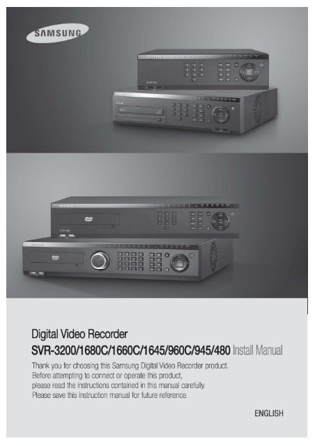
Install Manual0
Install Manual`IntroductionThank you for purchasing a Samsung SVR series digital video recorder.This manual is for SVR-3200, SVR-1680C, SVR-1660C, SVR-1645, SVR-960C, SVR-945,SVR-480. Before product installation and operation, please become thoroughly familiar with thisuser manual and other manuals referenced by this manual.This user manual and the software and hardware described here are protected by copyright law.With the exception of copying for general use within fair use, copying and reprinting the usermanual, either partially or in entirety, or translating it into another language without the consentof Samsung Techwin, Inc. is strictly prohibited.This specification may change without prior notice for improvement of product performance.Product Warranty and Limits of ResponsibilityThe manufacturer does not assume any responsibility concerning the sale of this product anddoes not delegate any right to any third party to take any responsibility on its behalf. Theproduct warranty does not cover cases of accidents, negligence, alteration, misuse or abuse.No warranty is offered for any attachments or parts not supplied by the manufacturer.The warranty period for this product is for 3 years from the date of purchase. The followingcases are not covered by the warranty and payment is required for repairs.Malfunctions due to negligence by the userDeliberate disassembly and replacement by the userConnection of a power source other than a properly rated power sourceMalfunctions caused by natural disasters (fire, flood, tidal wave, etc.)Replacement of expendable parts (HDD, FAN, etc.)※ The warranty period for the HDD and Fan is one year after purchase.Warranty only refers to the warranty covering products that have been paid for.1
Install ManualAfter the expiration of the warranty period (3 years), examination and repair will be provided fora fee. Even during the warranty period, repair and examination of items outside the warrantyscope will require payment.This product is not for exclusive use of crime prevention but for assistance in cases asfire or theft. We take no responsibility for damage from any incident.Experience and technical skills are needed for the installation of this product as an improperinstallation may cause fire, electric shocks, or defects. Any installation job should be performedby the vendor you purchased this product from.This manual is authored SVR-3200, SVR-1680C, SVR-1660C, SVR-1645, SVR-960C, SVR-945,SVR-480 according to firmware version 1.8.0The content of this manual may differ according to Firmware or Software upgrades, and thestandard and appearance of the product is changeable without prior notice to users.2
Install ManualContentsIntroduction ..................................................................................... 1Product Warranty and Limits of Responsibility ............................................................ 1Chapter 1. Safety Precautions ....................................................... 41.1 Explaining the Symbols ................................................................................. 4Chapter 2. Summary ....................................................................... 82.1 Features .................................................................................................... 82.1 Components ............................................................................................. 122.2 Description of product ................................................................................. 132.2.1 Front view .......................................................................................... 132.2.2 Rear Part ........................................................................................... 232.2.3 Remote control ................................................................................... 29Chapter 3. <strong>Installation</strong> .................................................................. 313.1 <strong>Installation</strong> & Connection ............................................................................. 313.1.1 Basic connection and operation .............................................................. 313.2 OSD Menu structure & Operation .................................................................. 333.2.2 Remote control setup & basic operation ................................................... 343.2.3 Example of installation structure ............................................................. 363.2.4 Basic setup ........................................................................................ 373.3 Using input/output terminals ......................................................................... 413.3.4 External Storage connections ................................................................. 563.3.5 Remote monitoring & control .................................................................. 63Trouble Shooting .......................................................................... 65Compatible HDD List .................................................................... 67Compatible Media List .................................................................. 67Specification ................................................................................. 67Dimensions ................................................................................... 713
Install ManualChapter 1. Safety Precautions1.1 Explaining the SymbolsWarningRefers to information users need to know in order to prevent serious injury ordeath.Before installation Verify the supplied voltage (AC100V~AC240V) before connecting to the power supply. Make sure the power supply is off before installation. Do not install in a very humid environment. Doing so may cause an electric shock orfire. Make sure ground line is connected to reduce electric shock risk.During operation Do not open the product cover except by qualified personnel or system installer.Opening the product cover may cause an electric shock. Do not plug multiple appliances into a single power outlet. Doing so may cause fire. Do not place dishes holding water or heavy objects on the product. Doing so maycause a malfunction. Do not use in areas where inflammable substances such as propane gas or gasolineor high amount of dust is present. Doing so may cause an explosion or fire. Do not touch the power line with a wet hand. Doing so may cause an electric shock. Do not insert a hand into the opening of the DVD. Doing so may cause an injury. Make sure conductive materials do not enter the cooling ventilator opening. Do not apply excessive force when pulling on the power cord. Damaging the cordmay cause an electric shock or fire. Improper replacement of the built-in battery by other types of batteries may causeexplosion. The batter must be replaced by the same battery type. Also, expiredbatteries may cause pollution and must be disposed of with care. Do not place the battery in fire or in extreme heat. Also, do not dissect or disassemblethe battery. Recharge the batteries for the remote controller.4
Install ManualDismantling and cleaning Do not dismantle, repair or modify the product deliberately. Doing so may cause adamage, an electric shock or an injury. Do not use water, paint thinner or organic solvent for cleaning the product exterior.Doing so may cause a malfunction or an electric shock. Use a dry cloth to clean theexterior.CautionProvides information users need to know in order to prevent minorinjury or product damage.During installation To get adequate ventilation, install the product with at least 15cm of space betweenthe cooling ventilation opening and a wall. To prevent falling, install the product in a flat area . Dropping the product maycause an injury or a malfunction. Avoid areas exposed to sun light or heat since they may cause deformation or amalfunction. If a camera is installed while the DVR is recording, image in another channel maybe disrupted. Start the storage after installing the camera is recommended.During use Make sure the product is not exposed to shocks or shaking when using the productor during moving. Do not move the product while it is in operation, and apply strong shocks to theproduct or throw the product. If hard disk drives other than those recommended are used additionally, abnormaloperation may occur. Inquire at the point of purchase of the product beforeinstalling such a hard disk drive. Product warranty will not cover deliberate additional use of such hard disk drives. This product is a supplementary rather than primary means for preventing fire andtheft. Our company is not responsible for incidence of incident or damage that mayoccur.5
Install ManualSamsung Techwin cares for the environment at all productmanufacturing stages, and is taking a number of steps to providecustomers with more environmentally friendly products. The Ecomark represents Samsung Techwin’s will to create environmentallyfriendly products, and indicates that the product satisfies the EURoHS Directive.FCC Compliance StatementNOTE : This equipment has been tested and found to comply with the limits for a Class A digitaldevice, pursuant to part 15 of the FCC Rules. These limits are designed to provide reasonableprotection against harmful interference when the equipment is operated in a commercialenvironment. This equipment generates, uses, and can radiate radio frequency energy and, if notinstalled and used in accordance with the instruction manual, may cause harmful interference toradio communications. Operation of this equipment in a residential area is likely to cause harmfulinterference in which cause the user will be required to correct the interference at his own expense.Correct Disposal of This Product(Waste Electrical & Electronic Equipment)(Applicable in the European Union and other European countries with separatecollection systems.) This marking shown on the product or its literature, indicates that itshould not be disposed with other household wastes at the end of its working life. Toprevent possible harm to the environment or human health from uncontrolled wastedisposal, please separate this from other types of wastes and recycle it responsibly to promote thesustainable reuse of material resources. Household users should contact either the retailer wherethey purchased this product, or their local government office, for details of where and how they cantake this item for environmentally safe recycling. Business users should contact their supplier andcheck the terms and conditions of the purchase contract. This product should not be mixed withother commercial wastes for disposal.Correct Disposal of Batteries in this Product(Applicable in the European Union and other European countries withseparate battery return systems.)This marking on the battery, manual or packaging indicates that the batteries in thisproduct should not be disposed of with other household waste at the end of theirworking life. Where marked, the chemical symbols Hg, Cd or Pb indicate that thebattery contains mercury, cadmium or lead above the reference levels in EC6
Install ManualDirective 2006/66. If batteries are not properly disposed of, these substances can cause harm tohuman health or the environment. To protect natural resources and to promote material reuse,please separate batteries from other types of waste and recycle them through your local, free batteryreturn system. The rechargeable battery incorporated in this product is not user replaceable.For information on its replacement, please contact your service provider.7
Install ManualChapter 2. SummaryThis unit is a digital video recording and playback device to record image and video inputfrom 32/16/9 channels to its built-in hard disk. The buttons on the front of the unit as wellas the mouse and GUI allow easy setup and operation.The Samsung SVR series of digital video recorders (DVRs) provide additional safety andsecurity to banks, apartment buildings and complexes, government offices as well asother public, private and commercial facilities. Recorded high-quality video and imagesare stored on hard disk for later retrieval or playback. Real time functionality deliversusers with the ability to simultaneously record multiple channels, playback video, andcopy video. A few of the more advanced user-conveniences include motion detection,Pan/Tilt/Zoom controls (PTZ), password protection, real time audio recording, event lists,and log files.2.1 FeaturesMonitoring ScreenThe monitoring screen supports vivid, high-definition live visual feed from each channel andprovides multiple screens. Real time MPEG-4 visual output (480 frames)Multiple split-screen monitoring modesSVR-3200/1680C/1660C/1645: Single, 4, 9, 10, 16SVR-960C/945: Single, 4, 9SVR-480 : Single, 4Automatic Screen Switching (AUTO)Supports various monitor output modesSVR-3200: 4 Composite, 2 VGASVR-1680C: 4 Composite, 1 VGASVR-1660C/1645/960C/945/480: 2 Composite, 1 VGAPan/Tilt, Digital Zoom, PIP (Picture-In-Picture), The PIP function will be available witha firmware upgrade in the future.8
Install ManualAudio RecordingSVR series DVRs provide real time audio recording. Simultaneous recording of 16/9/4 channels of audio in real timeSVR-3200/1680C/1600/1645 : Input - 16 channels (4 RCA in rear, 12 D-SUB),Output - 1 in rear, SVR-960C/945 : 9 channels (4 RCA in rear, 5 D-SUB),Output - 1 in rear, SVR-480 : 4 channels (4RCA), Output – 1 in rearSupports simultaneous recording and playbackVideo RecordingThe product is capable of storing visual image data as high resolution MPEG-4 video at upto 480 frames per second, as well as pre-emptively initiating recording sequences up to fiveseconds prior to an event. The COVERT feature (concealment of private visual data) helpsto protect privacy. High quality real time MPEG-4 recordingThree screen-resolution levels for improved control over data sizesMulti-recording for manual and scheduled eventsSimultaneous recording/playback/backup/networkingEasily accessible options for channel-specific resolution and motion detection rangesPer-second frame rates (up to 30 frames per channel) are user customizableSVR-3200 Half D1 : NTSC (704x240) 960fps, PAL (704x288) 800fpsSVR-1680C D1 : NTSC (704x480) 480fps, PAL (704x576) 400fpsSVR-1660C/1645 CIF : NTSC (352x240) 480fps, PAL (352x288) 400fpsSVR-960C/945 CIF : NTSC (352x240) 270fps, PAL (352x288) 225fpsSVR-480 D1 : NTSC (704x480) 120fps, PAL (704x576) 100fpsManual and scheduled recordingVideo signal loss detectionEvent logs (sensors, D-I/O, video loss, motion detection, text)9
Install ManualEach channel supports pre-emptive recording sequences up to 5 seconds prior to anactual eventSearch/PlaybackVarious search and playback options are offered for the user’s convenience. Playback by time, date and channelMouse interface increases data searchabilityForward/backward search while playback is pausedPlayback by event log entry (sensor, video loss, motion detection and text)Remote controller and Jog/Shuttle further improve searching (The SVR-960C/945/480 models do not support Jog/Shuttle.)Full-frame playback (Available in SVR-3200/1680C/1660C only)Data StorageThe hard disk included with the product is for data storage. If desired, recorded data can bebacked up or stored to DVD-R, CD-R or a USB storage device. The built-in hard disk is provided as primary storageMultiple portable data storage media are supported: DVD-R, CD-R and USB※ Refer to the appendix on the back of the manual regarding compatible media types.Hard disk expansion device (external recording device): SVS-5E (optional) Externalhard disk expansion is supported with the SVS-5E (Available for purchase separately)10
Install ManualNetworkingThe product supports LAN, xDSL and other networking capabilities. Combined with the PCinterface client, the core features of the device can be easily remotely controlled. E-mails can be sent via TCP/IP or DHCP upon an event triggerRemote live visual feed (single or 4 section split-screen)PC playback, storage, search and DVR control functions via Network ViewerRemote recording, search and playback schedulingSupports 10/100Mbps Ethernet/xDSLMultiple DVR connectionsMiscellaneousUser-friendly GUI and mouse interfaceSimplified firmware upgrades through USBVisual data recording and backup to USBSupports PTZ control (SPEED DOME), Coax, PRESETMultilingual support: Korean, English, Italian, Spanish, JapaneseSingle remote controller to control 16 DVRs11
Install Manual2.1 ComponentsPlease check the included accessories as follows.AC CORD Remote Controller Program CDSATA Cable HDD Mount Screw Install ManualDVR Quickguide SNM-128S Quickguide Rackmount & ScrewFor the SVR-945, a switched-mode power supply (SMPS) power cord is included, while a standis included instead of the standard rack mount. SVR-480 does not include rack mount & Screw.AC CORD & SMPSSTAND12
Install Manual2.2 Description of product2.2.1 Front view2.2.1.1 SVR-3200No. Classification Function1DVD-Multi for For copying recorded video and images to DVD/CDcopyingoptical media.2 Channel LED Shows the data input and event operation status3 JOG/SHUTTLEJog can adjust setting values, control the STEP function,navigate through the menu, and adjust the playbackspeed and direction. Shuttle controls PTZ.4 Channel button Selects channel in live feed or playback5 AUTO Starts or stops user defined sequences.6 MULTI Changes split-screen sections for live video feeds orplayback.7 MENU Navigates into the Menu.8 SEARCH Starts Search mode.9 REC button Starts or stops manual recordingREC lampLit when recording.HDD lampLit when HDD is working.10 NETWORK lamp Lit when network is connected.EVENT lamp Lit when an event is detected.COPY lamp Indicates copying operation.13
Install ManualPLAY lampLit when copying.11 Power button Turns on or off the device.12 ESC button The Escape button navigates up the menu tree andcloses dialog windows.13 COPY Starts Copy mode.14 FUNC Starts Function mode.15 MONITOR Cycles through from Monitor 1 to 4.16 PTZ Starts or ends PTZ function.17USB ports for external devices (mouse, USB memoryUSB1, USB2stick).18 PLAY/ENTER Start playback or select an item on the menu.19 ◀/REW Navigates or selects in the menu, or for playback,changes the reverse playback speed.20 ▶/FWD Navigates or selects in the menu, or for playback,changes the forward playback speed.31 ▲/PAUSE Navigates or selects in the menu, or for playback,pauses live or recorded video.22▼/STOPNavigates or selects in the menu, or for playback, stopsplayback.14
Install Manual2.2.1.2 SVR-1680C, SVR-1660C, SVR-1645No. Classification Function1DVD-Multi for For copying recorded video and images to DVD/CDcopyingoptical media.2 Channel LED Shows the data input and event operation status3 JOG/SHUTTLEJog can adjust setting values, control the STEP function,navigate through the menu, and adjust the playbackspeed and direction. Shuttle controls PTZ.4 Channel button Selects channel in live feed or playback5 AUTO Starts or stops user defined sequences.6 MULTI Changes split-screen sections for live video feeds orplayback.7 MENU Navigates into the Menu.8 SEARCH Starts Search mode.9 REC button Starts or stops manual recordingREC lampLit when recording.HDD lampLit when HDD is working.10NETWORK lamp Lit when network is connected.EVENT lamp Lit when an event is detected.COPY lamp Indicates copying operation.PLAY lamp Lit when copying.11 Power button Turns on or off the device.12 ESC button The Escape button navigates up the menu tree and15
Install Manualcloses dialog windows.13 COPY Starts Copy mode.14 FUNC Starts Function mode.15 MONITOR Cycles through from Monitor 1 to 4 : SVR-1680C,Switches from main and sub monitor : SVR-1660C,SVR-164516 PTZ Starts or ends PTZ function.17USB ports for external devices (mouse, USB memoryUSB1, USB2stick).18 PLAY/ENTER Start playback or select an item on the menu.19 ◀/REW Navigates or selects in the menu, or for playback,changes the reverse playback speed.20 ▶/FWD Navigates or selects in the menu, or for playback,changes the forward playback speed.31 ▲/PAUSE Navigates or selects in the menu, or for playback,pauses live or recorded video.22▼/STOPNavigates or selects in the menu, or for playback, stopsplayback.16
Install Manual2.2.1.3 SVR-960CNo. Classification Function1DVD-Multi for For copying recorded video and images to DVD/CDcopyingoptical media.2 Channel LED Shows the data input and event operation status3 Channel button Selects channel in live feed or playback4 AUTO Starts or stops user defined sequences.5 MULTI Changes split-screen sections for live video feeds orplayback.6 MENU Navigates into the Menu.7 SEARCH Starts Search mode.8 REC button Starts or stops manual recordingREC lampLit when recording.HDD lampLit when HDD is working.9NETWORK lamp Lit when network is connected.EVENT lamp Lit when an event is detected.COPY lamp Indicates copying operation.PLAY lamp Lit when copying.10 Power button Turns on or off the device.11 ESC button The Escape button navigates up the menu tree andcloses dialog windows.12 COPY Starts Copy mode.13 FUNC Starts Function mode.17
Install Manual14 MONITOR Switches from main and sub monitor15 PTZ Starts or ends PTZ function.16USB ports for external devices (mouse, USB memoryUSB1, USB2stick).17 PLAY/ENTER Start playback or select an item on the menu.18 ◀/REW Navigates or selects in the menu, or for playback,changes the reverse playback speed.19 ▶/FWD Navigates or selects in the menu, or for playback,changes the forward playback speed.20 ▲/PAUSE Navigates or selects in the menu, or for playback,pauses live or recorded video.21▼/STOPNavigates or selects in the menu, or for playback, stopsplayback.18
Install Manual2.2.1.4 SVR-945No. Classification Function1 Channel LED Shows the data input and event operation status2 Channel button Selects channel in live feed or playback3 AUTO Starts or stops user defined sequences.4 MULTI Changes split-screen sections for live video feeds orplayback.5 MENU Navigates into the Menu.6 SEARCH Starts Search mode.7 REC button Starts or stops manual recordingREC lampLit when recording.HDD lampLit when HDD is working.8NETWORK lamp Lit when network is connected.EVENT lamp Lit when an event is detected.COPY lamp Indicates copying operation.PLAY lamp Lit when copying.9 Power button Turns on or off the device.10 ESC button The Escape button navigates up the menu tree andcloses dialog windows.11 COPY Starts Copy mode.12 FUNC Starts Function mode.13 MONITOR Switches from main and sub monitor19
Install Manual14 PTZ Starts or ends PTZ function.15USB ports for external devices (mouse, USB memoryUSB1, USB2stick).16 PLAY/ENTER Start playback or select an item on the menu.17 ◀/REW Navigates or selects in the menu, or for playback,changes the reverse playback speed.18 ▶/FWD Navigates or selects in the menu, or for playback,changes the forward playback speed.19 ▲/PAUSE Navigates or selects in the menu, or for playback,pauses live or recorded video.20▼/STOPNavigates or selects in the menu, or for playback, stopsplayback.20
Install Manual2.2.1.5 SVR-480No Classification Function1DVD-Multi for For copying recorded video and images to DVD/CD opticalcopyingmedia.2 Channel button Selects channel in live feed or playback3 Channel LED Shows the data input and event operation status4 AUTO Starts or stops user defined sequences.5 MULTI Changes split-screen sections for live video feeds orplayback.6 MENU Navigates into the Menu.7 SEARCH Starts Search mode.8 REC button Starts or stops manual recordingREC lamp Lit when recording.HDD lamp Lit when HDD is working.NETWORK Lit when network is connected.9 lampEVENT lamp Lit when an event is detected.COPY lamp Indicates copying operation.PLAY lamp Lit when copying.10 Power button Turns on or off the device.11 USB1, USB2 USB ports for external devices (mouse, USB memory stick).12 ESC button The Escape button navigates up the menu tree and closes21
Install Manualdialog windows.13 COPY Starts Copy mode.14 FUNC Starts Function mode.15 MONITOR Switches from main and sub monitor16 PTZ Starts or ends PTZ function.17 PLAY/ENTER Start playback or select an item on the menu.18 ◀/REW Navigates or selects in the menu, or for playback, changesthe reverse playback speed.19 ▶/FWD Navigates or selects in the menu, or for playback, changesthe forward playback speed.20 ▲/PAUSE Navigates or selects in the menu, or for playback, pauseslive or recorded video.21▼/STOPNavigates or selects in the menu, or for playback, stopsplayback.22
Install Manual2.2.2 Rear Part2.2.2.1 SVR-3200No. Input/OutputFunctionterminal name1 POWER IN Socket for AC 100V ~ AC 240V power cord.2 CH1 ~ 32 Connection terminal for camera BNC input.3 MONITOR 1 ~ 4 Connection terminal for monitor BNC output.4 AUDIO IN(RCA) RCA audio jack for RCA input.5 AUDIO OUT Audio jack for speaker output.6 GROUND Ground terminal between DVR and external device.7 ETHERNET Ethernet port for network connections (RJ-45).8 STORAGE External storage connection port (Function not supported in thecurrent version)9 eSATA Connection terminal for external eSATA HDD or HDD for backups.10 VGA OUTPUT 2 Output port for PC monitor.11 VGA OUTPUT 1 Output port for PC monitor.12 Serial Port (TerminalBlock)Connection terminal for expanded controller, speed dome camera,etc.RS-232C/485/42213 Serial Port (D-Sub) RS-232C D-SUB connector.14 RELAY OUT Connection terminal for relay output.23
Install Manual15 SENSOR IN Connection terminal for sensor input.16 AUDIO IN(D-SUB) Connection terminal for audio output D-SUB.17 D-I/O Connection terminal for DIGITAL IN/OUT.24
Install Manual2.2.2.2 SVR-1680C, SVR-1660C, SVR-1645No. Input/OutputFunctionterminal name1 POWER IN Socket for AC 100V ~ AC 240V power cord.2 CH1~16 Connection terminal for camera BNC input.3 LOOP OUT Connection terminal for camera BNC output (loop).4 MONITOR 1 ~ 2 Connection terminal for monitor BNC output.5 AUDIO IN(RCA) RCA audio jack for RCA input.6 AUDIO OUT Audio jack for speaker output.7 GROUND Ground terminal between DVR and external device.8 ETHERNET Ethernet port for network connections (RJ-45).9 STORAGE External storage connection port (Function not supported inthe current version)10 eSATA Connection terminal for external eSATA HDD or HDD forbackups.11 VGA OUTPUT Output port for PC monitor.12 Serial Port (TerminalBlock) RS-232C/485/422Connection terminal for expanded controller, speed domecamera, etc.13 Serial Port (D-Sub) RS-232C D-SUB connector.14 RELAY OUT Connection terminal for relay output.15 SENSOR IN Connection terminal for sensor input.16 AUDIO IN(D-SUB) Connection terminal for audio output D-SUB.17 D-I/O Connection terminal for DIGITAL IN/OUT.25
Install Manual2.2.2.3 SVR-960CNo. Input/OutputFunctionterminal name1 POWER IN Socket for AC 100V ~ AC 240V power cord.2 GROUND Ground terminal between DVR and external device.3 CH1~9 Connection terminal for camera BNC input.4 LOOP OUT Connection terminal for camera BNC output (loop).5 MONITOR 1 ~ 2 Connection terminal for monitor BNC output.6 AUDIO IN(RCA) RCA audio jack for RCA input.7 AUDIO OUT Audio jack for speaker output.8 ETHERNET Ethernet port for network connections (RJ-45).9 eSATA Connection terminal for external eSATA HDD or HDD for backups.10 VGA OUTPUT Output port for PC monitor.11 Serial Port (D-Sub) RS-232C D-SUB connector.12 Serial Port (TerminalBlock)Connection terminal for expanded controller, speed dome camera,etc.RS-232C/485/42213 RELAY OUT Connection terminal for relay output.14 SENSOR IN Connection terminal for sensor input.15 AUDIO IN(D-SUB) Connection terminal for audio output D-SUB.16 D-I/O Connection terminal for DIGITAL IN/OUT.26
Install Manual2.2.2.4 SVR-945No. Input/OutputFunctionterminal name1 CH1~9 Connection terminal for camera BNC input.2 LOOP OUT Connection terminal for camera BNC output (loop).3 MONITOR 1 ~ 2 Connection terminal for monitor BNC output.4 AUDIO IN(RCA) RCA audio jack for RCA input.5 AUDIO OUT Audio jack for speaker output.6 ETHERNET Ethernet port for network connections (RJ-45).7 eSATA Connection terminal for external eSATA HDD or HDD forbackups.8 VGA OUTPUT Output port for PC monitor.9 Serial Port (D-Sub) RS-232C D-SUB connector.10 Serial Port (TerminalBlock) RS-232C/485/422Connection terminal for expanded controller, speed domecamera, etc.11 RELAY OUT Connection terminal for relay output.12 AUDIO IN(D-SUB) Connection terminal for audio output D-SUB.13 SENSOR IN Connection terminal for sensor input.14 D-I/O Connection terminal for DIGITAL IN/OUT.15 GROUND Ground terminal between DVR and external device.16 POWER IN Socket for AC 100V ~ AC 240V power cord.27
Install Manual2.2.2.5 SVR-480No. Input/OutputFunctionterminal name1 GROUND Ground terminal between DVR and external device.2 CH1~4 Connection terminal for camera BNC input.3 LOOP OUT Connection terminal for camera BNC output (loop).4 MONITOR 1 ~ 2 Connection terminal for monitor BNC output.5 AUDIO IN(RCA) RCA audio jack for RCA input.6 AUDIO OUT Audio jack for speaker output.7 ETHERNET Ethernet port for network connections (RJ-45).8 eSATA Connection terminal for external eSATA HDD or HDD fobackups.9 Serial Port (D-Sub) RS-232C D-SUB connector.10 VGA OUTPUT Output port for PC monitor.11 Serial Port (Terminal Block)RS-485/422Connection terminal for expanded controller, speeddome camera, etc.12 RELAY OUT Connection terminal for relay output.13 SENSOR IN Connection terminal for sensor input.14 POWER IN Socket for AC 100V ~ AC 240V power cord.Please refer to the detailed description for installation & use in the “Install Manual”.28
Install Manual2.2.3 Remote controlAll DVR unit features can be controlled with the remote controller; 16 units can be controlledwith a single remote controller. Unit IDs should be set in the DVR Menu > Communication >Remote > Remocon ID.No. Classification Function1 ID Selects ID.2 FUNC Starts function mode.3 MULTI Changes split-screensections for live video orplayback.4 STATUS Displays system setupinformation.5 MON Changes screen to spotmonitor.6 DISP Selects split-screen andchannel options.7 AUTO Switches to automaticdisplay.8 ZOOM Executes digital zoom.9 PIP Displays picture-in-picture.10 PTZ Switches to PTZ mode.11 Channel buttons Changes channels.12 RECORD ( ) Starts and stops manualrecording.13 +10 Uses for channels over 9(e.g. "+10” + “1”)14 FN1 Spare button 1.15 FN2 Spare button 2.16 MENU Switches to menu screen.17 COPY Displays copy menu andsaves recorded video toexternal storage device(USB).29
Install ManualNo. Classification Function18 (◀) Moves cursor left in setupmenu.19 (▶) Moves cursor right insetup menu.20 (▲) Moves cursor up in setupmenu.21 (▼) Moves cursor down insetup menu.22 ENTER Saves settings and execute.23 ESC Cancels settings ornavigates up in menu.24 SEARCH( ) Displays the search menu.25 FASTFast reverses playback.REWIND(◀◀)26 REWINDReverses playback.PLAY(◀)27 FORWARD Forwards playback.PLAY(▶)28 FASTFast forwards playback.FORWARD(▶▶)29 STOP( ) Stops playback.30 STEPREVERSE(◀l)Reverses playback frame byframe.31 STEPFORWARD(l▶)Forwards playback frame byframe.32 PAUSE(ll) Pauses playback.33 P/T Controls PAN/TILT.34 LOAD PRESET Loads presets.35 AUX ON Turns auxiliary on.30
Install ManualChapter 3. <strong>Installation</strong>3.1 <strong>Installation</strong> & Connection3.1.1 Basic connection and operation3.1.1.1 Camera connectionConnect the DVR and CCTV cameras using coaxial cable as in the following figure.- The cameras’ video input type must be one and only of NTSC or PAL. Both types should notbe used together.- Automatic settings for 75Ω terminal resistanceWhile terminal resistance is generally 75Ω with only one video input port in use, when thelower video input port is also connected, the settings automatically separate into 75Ω terminalresistance while the status is Hi-Z (high impedance).- The video input type (NTSC/PAL) is automatically recognized when the device is operation.When multiple cameras are used, the video input type is taken from the first camera detectedstarting from channel 1 and progressing sequentially to channel 16.3.1.1.2 Monitor connectionMonitors connect to the DVR unit using a video cable as shown in the following figure.31
Install Manual3.1.1.3 Audio connectionAudio equipment connects to the DVR unit using RCA audio cables or D-SUB as shown in thefollowing figure. SVR-480 does not support D-SUB audio.Refer to the following figure when connecting D-SUB. The audio inputs are pin numbers 5 ~ 16.3.1.1.4 Power connection & operationConnect the power cable as shown in the following figure.- The DVR unit will boot automatically when the power is connected.- To turn the DVR unit off, press the power button for 5 seconds, then choose “Yes” when thepower-off dialog appears.- To turn the power on again, press the power button.32
Install Manual3.2 OSD Menu structure & Operation3.2.1 Menu structurePress the [MENU] button on the front panel to change to setup mode and display the followingdialog.Main menuSub menuSetup dialogbox(1) Main menu: The currently selected tab is highlighted in blue with submenus and optionsdisplayed below. Use the cursor [◀/▶] keys to navigate between submenu items then press[Enter] to activate it.(2) Sub menu: The currently selected submenu name is displayed in the title bar. Use thecursor [◀/▶] keys to navigate across submenus and press [Enter] to display it in the dialog box.Press [ESC] to navigate up to the main menu tabs.(3) Setup dialog box: The currently selected setting is highlighted in blue. Use the cursor[◀/▶] keys to move between settings and press [Enter] or [▼] to enter edit mode and change asetting. All setting values are either numeric or text based. Use the cursor [◀/▶] or [▲/▼] keysto edit numeric values. Text based values are edited with the character input dialog. To save avalue and resume navigation, press [ESC]. Press [ESC] again to navigate up to the main menu.33
Install Manual3.2.1.1 Character input dialog boxThe characters input dialog lets you input text.Character inputUse the cursor [▲/▼] and [◀/▶] keys to choose characters then press [Enter] to input it. Use[] to backspace, and [] to insert a space. When finished, press [Enter] to exit the characterinput dialog with the newly inputted value.3.2.2 Remote control setup & basic operation3.2.2.1 ID setupWhen operating multiple units, a single remote controller can be used to control all of them byassigning each unit a unique ID. Setup each unit's unique ID as follows.(1) Press [MENU].(2) Press [▶] to select “Network” then press [Enter] or [▼].(3) Press [▼] to select “Remote” then press [Enter].(4) Press [▶] to select “Remote Control ID” then press [Enter].(5) Adjust the ID value using [◀/▶] then press [ESC].(6) Press [ESC] several times until you are back in monitor mode.34
Install ManualRemote Control ID supports a maximum of 16 IDs.For unused remote controllers, set Remote Control ID to Off.3.2.2.2 Selecting IDsAll DVR unit features can be controlled with the remote controller; 16 units can be controlledwith a single remote controller. Unit IDs should be set.1) Check the remote controller ID in DVR Menu.2) Press the ID button on the remote controller.3) Press the number button on the remote controller.If the remote controller ID and the DVR ID are the same, the DVR buzzer beeps3.2.2.3 Usable range of Remote Controller3.2.2.4 Inserting and changing batteries in the Remote ControllerThe remote controller takes AAA sized batteries.1. Open the battery cover onthe back.2. Check the positive(+) andnegative(-) battery polesand insert or replace thebatteries.3. Close the battery cover.35
Install Manual3.2.3 Example of installation structure3.2.3.1 Basic connection diagramConnect the cameras, monitors and audio.3.2.3.2 Extended connection diagramConnect the cameras, monitors, audio, sensors, relays and other peripherals.3.2.3.3 External storage and backup connection diagramConnect a USB memory device or a “Samsung SVS-5E external HDD (eSATA)” unit.36
Install Manual3.2.3.4 Internet/Intranet connection diagram3.2.4 Basic setup3.2.4.1 Video checkThe product automatically powers on when the power cord is plugged in. Once it finishesbooting up, the default 16 channel split-screen is displayed.If a password for the unit has been set, the password input dialog is displayed.Only the numeric buttons work here and all others are temporarily disabled untilthe correct password is entered. (The factory default has no password protection.)3.2.4.2 Date & time setup- Press [MENU] and select “Quick Setup” when the OSD menu appears.- After selecting “System Time”, press [Enter].37
Install ManualTime Zone(1) Press [◀/▶] or [▲/▼] to select “Time Zone”, and then press [Enter].(2) Press [◀/▶] to set the correct Time Zone, and then press [ESC].Daylight Saving(1) When selecting a Daylight Saving Time zone, Daylight Saving automatically changes to On,and is Off for other time zones.(2) To customize the start and end time of DST, use the [◀/▶] buttons and change DaylightSaving to Custom.(3) Changing Daylight Saving to Custom displays the Custom DST Setup options.Upon clicking on Custom DST Setup, two setup methods display.The first is for selecting a month and date to define the start and end times of DST.38
Install ManualThe second is for selecting a month, week, and day to define the start and end times of DST.Date Format(1) Press [◀/▶] or [▲/▼] to select “Date Format”, and then press [Enter]. Press [◀/▶] toselect a date format: YYYY/MM/DD, MM/DD/YYYY, or DD/MM/YYYY.(2) Press [ESC] to exit edit mode.Time(1) Press [◀/▶] or [▲/▼] to select “Time”, and then press [Enter].(2) Press [◀/▶] to individually select “Date” and “Time”. Press [▲/▼] to set the proper valuesfor each.(3) Press [ESC] to exit edit mode.Apply Date/TimeSetting a new date and/or time has a serious impact on the HDD recording file system. As such,unlike other settings that are automatically saved, the date and time settings must be manuallysaved to avoid the possibility of an inadvertent change. Click the [Apply Date / Time] button toconfirm and save the settings.39
Install Manual(1) Press [◀/▶] or [▲/▼] to select “Apply Date / Time” and then press [Enter]. A confirmationdialog is displayed as shown below.(2) Press [◀/▶] or [▲/▼] to select “YES” and then press [Enter]. Press [ESC] to cancel thenew date/time and return to the original value from before.3.2.4.3 Record setupPress [Menu] and select “Quick Setup” when the OSD menu appears.Program setupThis menu allows user to set resolution, frame rates, and quality for each channel individually.Please refer to the “Record setup” sections for more information.40
Install ManualSchedule SetupSelect the “Schedule & Event” option, and set the Day & Time options.How to check the record statusIf the record setup is configured correctly, [REC LED] on the front panel willlight up RED. Also, record status [S] will be displayed on the video screen.[S] indicates scheduled recording.3.3 Using input/output terminals3.3.1 Handling cable endsThe following details how to handle cables for the terminal block. Please note that differentgauges of wire are needed for stranded wire and solid wire.41
Install Manual- Stranded wire: Strip 8 ~ 10mm of insulation off the end of the wire and solder it together. UseAWG 22 ~ 26 wire.- Solid wire: Strip 8 ~ 10mm of insulation off the end of the wire. Use AWG 20 ~ 26.3.3.2 Wire insertion/removalWhen inserting/removing wires to/from the terminal block, push the driver as shown below andinsert or remove the wire.3.3.3 Sensor connections & settings3.3.3.1 SpecificationThe sensor specifications are as follows.SpecificationElectriccapacityNo. of inputsInput typesSupport SensorConnection methodPulse width of usableinputOutput power16 transistor inputN.C, N.O supportDry contact sensorInsert stripped wire end into terminal blockMinimum 500msTypical DC 12mA42
Install ManualSensor input terminal connectionConnect sensors to S1 ~ S16 as illustrated in the figure below. Please note that the figureshows connecting sensors with dry contacts. Refer to the section on handling wiring for moreinformation about connecting or disconnecting sensor wires.Sensor Settings(1) Press [Menu] and select “Event” when the OSD menu appears.(2) Press [Enter] or [▼] to enter the submenu, select “Sensor” and press [Enter].AllThis allows setting all 16 sensors simultaneously to off or Normal Open (N.O.) / Normal Close(N.C.).(1) Set the input type after setting "All".43
Install ManualIndividual sensorThis option allows setting each of the 16 sensor input types individually.(1) Select a sensor then press [Enter].(2) Set the input type for the selected sensor.(3) Press [ESC] to exit to the OSD menu when you are finished.Sensor setup lets you choose whether or not to use sensors and their type, andRecord & Relay setup, while set separately, should be set according to thesensor type. Please refer to the “Record setup”, the “Event Action” heading inthe “Event setup”, and “Relay out” sections for more information.3.3.3.2 Relay connections & settingsSpecificationThe alarm specifications are as follows.No. of outputs 4 relay outputsSpecificationOutput typeConnection methodDry contactInsert stripped wire end into terminal blockRatedcurrentDC30V 1AAC 125V 0.5A44
Install ManualRelay out connectionConnect relays to R1 ~ R16 as illustrated in the figure below. The example shows how toconnect a warning light. Refer to the section on handling wiring for more information aboutconnecting or disconnecting relay wires.Relay Out SettingsRelays can be triggered by following events; alarm sensor, motion detection, video loss, harddisk fail, hard disk full, fan fail, password fail, and DDNS registration failure. Relays can alsobe triggered remotely over the network using the Samsung Network Video Managementsoftware.For more information, refer to the user manual.The user manual can be downloaded from www.samsungcctv.com or on the CDprovided with the product.3.3.3.3 D-I/O (Digital Input/Output) connection & settingsThe D-I/O has 12 D-I/O ports and can accommodate 12 inputs/outputs. If sensors are working45
Install Manualas Relay out, the Output can be operated with digital I/O. Also, if Input is operated, theemergency recording is started. Then the emergency recording starts to record with the EventRecord value.SpecificationThe D-I/O specifications are as follows.No. of inputs/outputs 12SpecificationRatedcurrentOutput typeConnection methodDCDC 3V outputConnect stripped wire end with 15 pin D_SUB.3.3 ~ 5VD-I/O ConnectionD-I/O inputs/outputs are connected shown in the following figure. Please refer to the section onhandling wiring for information about connecting and disconnecting.D-I/O SettingsThe 12 D-I/O ports are split with 6 for input and 6 for output. They can be configured under theEvent Setup menu tab.46
Install ManualFor more information, refer to the user manual.The user manual can be downloaded from www.samsungcctv.com or on theCD provided with the product.3.3.3.4 Serial communication terminal connections & settingsSerial communication terminal connection for Pan/Tilt/ZoomPTZ cameras for the DVR unit can be connected through the COM port, and supported modelsconfigured through the OSD menu.The following figures illustrate how to connect PTZ cameras through the RS-422/485 port(COM2/COM4) and how to connect other devices through the serial port connection terminals.cRefer to the section on handling wiring for more information about connecting or disconnectingwires.[SVR-3200, 1680C, 1660C] [SVR-1645, 960C, 945]47
Install ManualSerial Comm. Terminal Connection DiagramCOM1 connection diagram(RS-232)COM2 connection diagram (RS-422/485)RS-422(SVR-3200, 1680C, 1660C)RS-485(All SVR series )48
Install ManualCOM3 connection diagram (RS-232)PTZ, Keyboard Compatible ListModelSDZ160/330, Samsung SPDKeyboard SCC3000, Samsung SRX-100BBOSCH AutoDome, TC8560X-4PELCO(P), PELCO(D)Honeywell 755/655, HRX-2000, ScanDome2Sony EVI-D3xVT VPT-4xAD SpeedDomeSungJin SJ372R1’Samsung SCC641Panasonic WV-CS850LG GAC-PT2Keyboard KBD300A, WGI SPD1800/2600Merit-Lilin FastDomeElmo PTC200CCanon VC-C4HTC-230SRVisionElbexVIDOVICONHuntORX-1000Fine CRR-1600ManufacturerSAMSUNG TECHWINBOSCHPELCOHONEYWELLSONYVTADSUNGJINSAMSUNG ELECTRONICSPANASONICLGWEBGATE Inc.MERITELMOCANOND-MAXRVISIONELBEXVIDOVICONHUNTSYSMANIALIVEI49
Install ManualTokinaKodicom KRENuvicoTOKINAKODICOMNUVICOSerial SettingsA total of four serial ports are available for the DVR. Two are RS-232C(Com1, Com3) and theother two are RS-422/485(Com2, Com4).The Serial Port settings are available under Communication > Remote.The following options are provided for the Serial Port settings.PTZ(Serial)Select PTZ.To control the PTZ operation via serial port, select PTZ in the Device options, and then set up aserial port. To control the PTZ operation via coax protocol, you do not need to set up this option.50
Install ManualTypeSelect a serial port.ProtocolSelect a connected PTZ device.Camera IDEnter the ID of the selected camera.InterfaceSelect one from among Com2 to 4.To use RS-232, select Com3. For RS-422 or 485, select Com2 or 4.Baud rate/Parity/Stop Bit/Data BitEnter the same settings as the ones for the PTZ device.Idle TimeActivate or disable PTZ Home, and set up a standby duration for the device beforemoving toPTZ home.PTZ(Coax)The Coax Protocol option does not support normal PTZ protocols, but rather supports the PelcoStandard and Extended Protocols.The standard protocol supports basic PTZ functions such as PTZ and presets. The extendedprotocol supports more expansive features such as menu control and video playback in additionto the basic PTZ functions.To use this option, a PTZ device must be embedded with a coax standard or extended protocol.51
Install ManualTypeSelect Coax.ProtocolSelect Pelco or Pelco Extended according to the coax protocol type of Pelco camera.AD Dome does not support menu control, Presets or AUX when setup with acoax protocol.Idle TimeActivate or disable PTZ Home, and setup a standby duration of the device before moving toPTZ home.3.3.3.5 External device connection using Serial portText Input Device Connection (ATM / POS / Access Control)Text and video data from POS/ATM terminals can be synchronously recorded throughCOM1/RS-232.As shown in the above figure, COM1/RS-232 (9-pin D-SUB) are used to receive text data that isconfigured under the OSD Communication > Event menu.52
Install ManualSerial Settings (COM1)(1) In the OSD menu, navigate to Communication > Serial.(2) Set the “Serial Number” option to COM1 for text.(3) Set the Baud Rate/Parity/Stop bit/Data bit options identical to the Input device.Text Settings(1) On the OSD menu, select Event Setup > Text.(2) Set text and relations options.Some external devices may not be recognized. Please consult your productdistributor prior to installation.3.3.3.6 USB device connectionsThe USB ports are mainly used to copy video data to supported external USB storage deviceslike USB memory sticks (copies data within an hour).53
Install ManualSupported USB devices conform to the following specifications.USB Spec. Ver. 2.0Supported devicetypesUSB memory stickOutputvoltage/currentMax. 200mA per DC 5V / PortThe storage device should be formatted with the FAT32 file system.Supported storage devices are automatically recognized when copying. To copy video, setcopying options in the Copy dialog, select the storage device, then copy the data.[CD/DVD Copy][RE4 Copy]Select the channel to copy.[SVR-960C/945] [SVR-1680C/1660C/1645] [SVR-3200]54
Install Manual[AVI Copy]Some USB storage devices may require additional software and drivers. Careshould be taken in these cases as the DVR may not recognize some USBproducts like this. If copied files do not playback on another computer, doublecheck that proper playback software and codecs are installed.3.3.3.7 Video in/out connectionsThe DVR video input/output are “Loop through" and detect connection status automatically toset terminal resistance.For example, when only video input is connected, terminal resistance is internally set to 75Ω.However, when video input and output are connected, terminal resistance is set to Hi-Z. As such,when input and output are connected, the external output device should have its resistance setto 75Ω.55
Install Manual3.3.3.8 Audio in/out connectionsThere are 4 RCA audio in and 12 D-SUB audio in.All 16 audio sources can be monitored through a single output.The 12 D-SUB audio inputs use terminals 5 ~ 16 and are connected as shown in the followingfigure.3.3.4 External Storage connections3.3.4.1 eSATA PortOne eSATA external storage device can be connected through the eSATA port in the back of theDVR unit for a maximum of 8TB of storage space.The eSATA port only supports the “SVS-5E” eSATA external HDD from SamsungTechwin.3.3.4.2 eSATA device connectionUse the eSATA port in the back of the DVR unit to connect your SVS-5E external HDD. Externalstorage requires its own power source as the DVR unit does not supply power to it.Since some external devices may not be recognized if connected with the DVRunit on, the following procedure should be followed.56
Install Manual1. Turn DVR power OFF.2. Connect external device and eSATA interface cable.3. Turn external device power ON.4. Turn DVR Power ON.3.3.4.3 Supported HDDRefer to the appendix in the back of the manual for information on supported HDDs.3.3.4.4 Registering & formatting HDDsWhen the DVR is first booted after a new HDD is physically installed, the "Disk Manager"automatically runs as shown in the following figure.If the “Disk Manager” does not run, check that the HDD is properly installed.(1) Press [Enter] with “Disk Manager” selected.(2) Press [▲/▼] to select the new HDD (“No” under the “Enabled” column heading), and thenpress [Enter].(3) If prompted to format the disk, select “YES”.(4) Close “Disk Manager” by pressing [ESC].3.3.4.5 Attaching & Detaching HDDPlease follow the instructions below to add or replace an HDD.Attaching an HDDAttach the enclosed HDD fixture screws to both sides of the HDD.With 2 fixture screws to a side, attach 4 screws to the HDD.The following picture shows an HDD attached with 4 fixture screws.57
Install ManualOnce the HDD is attached with the screws, insert it into an HDD bracket.For the location of HDDs, IntA is the bottom right, IntB is the upper right, IntC is the bottom left,and IntD is the upper left.The following picture shows an HDD being inserted to IntA.When attaching an HDD, first insert the front part of the HDD to the bracket, and then pressdown on the other side with the SATA port.Once the HDD is inserted, connect the SATA and power cables.As shown in the picture below, connect the enclosed SATA cable, and then an SMPS powercable.The following picture shows the product attached with the maximum 4 HDDs.58
Install ManualAfter inserting the HDD, fasten the HDD fixture bracket as shown in the picture below.Now the HDD is fully attached to the product.59
Install ManualTo enable the newly attached HDD, you must change the availability of the HDD to "Yes" underthe DVR Disk menu.To access the menu, go to Menu > System Settings > Disk > Disk Manager.The newly attached HDD will display in the HDD list with No in the Availability pane.To change the availability, place the cursor on No and then press Enter.When a dialog window appears, select "Yes." Now the HDD is ready to use.60
Install ManualDetaching HDDDetaching an HDD is the same as attaching it, but in reverse order.Loosen the HDD fixture bracket. Unplug the SATA and power cables.Detach the HDD.When detaching an HDD, first lift up the back part of the HDD with the SATA port, and then thefront part. Remove or keep the HDD fixture screws in case you want to attach an HDD later.61
Install ManualGo to Menu > System Settings > Disk > Disk Manager.Select the detached HDD, and the press Enter. Select "Yes" in the dialog window and removethe HDD from the HDD list.62
Install Manual3.3.5 Remote monitoring & controlConnections can be made through Internet/Intranet by using the remote computer. Thisconnection can be used to control DVRs and monitor areas same as local spot.3.3.5.1 Ethernet connection(1) Shut the DVR power off.(2) Connect the Ethernet cable to the DVR and hub or router.(3) Turn the DVR power on.To prevent damage to the DVR, turn the power on after connecting the Ethernetcable. The Ethernet cable should be securely connected. After powering on theDVR, check the connection.3.3.5.2 Network settingsThe following describes settings for Ethernet.Refer to “User Manual” when using xDSL for detailed setup instructions.The user manual can be downloaded from www.samsungcctv.com or found onthe CD provided with the product.63
Install ManualWhen using EthernetSet the type to Ethernet and fill in the IP address, Netmask, Gateway, and DNS informationprovided by your network administrator. Use Up/Down direction keys or the mouse wheel toselect the items, and then setup with the appropriate values.When using PPPoEChange the network configuration type to xDSL then navigate to the xDSL menu.Change the port from Ethernet. (IMPORTANT: You must remember the port.)In the xDSL screen, input the login ID and password that you received when you registered forPPPoE.When using DDNSChange the DDNS polling interval to more than 1 minute and enter the login ID and passwordfor your DDNS server.64
Install ManualTrouble Shooting1. DVR does not boot• Check power• Check power cord2. Monitor does not display camera video• Check monitor power• Check cable between the monitor and DVR• Check monitor cable port• Check that DVR power is on3. Some channels do not display images• Check camera power• Check camera video input• Check DVR video input port• Check whether the Screen > Activity option is on/off• Check the Monitor > Covert option for privacy settings4. DVR does not record• Check Disk Manager to see that the HDD is installed• Check the Record settings5. DVR does not playback• Check the Record settings• Check for button activation6. Video is overly bright / dark• Check the camera settings• Check that video and power cables are properly plugged in• Check brightness and contrast settings under the “Screen” menu7. Remote controller does not work• Check the Remote controller battery• Check the Remote controller ID• Check Remote controller usage specifications65
Install Manual8. Front buttons do not work• Check DVR power• Check screen lock status9. Cannot connect to network• Check that network cable is properly connected• Check DVR IP address• Check PC IP address• Run a ping test10. When to contact your resellerIf any of the following happen, immediately turn of the DVR and contact the reseller thatyou purchased it from.• The product exhibits extremely abnormal behavior, e.g. strange noises, odors, orsmoke• The power jack is damaged• Rain, water, or other liquids get into the product• The product does not work as described in the user manual• The product has fallen and become damaged• Product performance changes significantly66
Install ManualCompatible HDD ListWestern DigitalCapacity Model1000GB WD10EVCS750GB WD7500AVCS500GB WD5000AVVS320GB WD3200AVVSCompatible Media ListDVD-R manufactureMitsubishi (16X)TDK (16X)Imation (16X)Sony (16X)CD-R manufactureMitsubishi (16X)TDK (16X)Imation (16X)Sony (16X)SpecificationItemDisplayVideoInputsResolutionLiveFrame rateResolutionMulti ScreenDescriptionSVR-3200 : 32 composite video 0.5–2 Vpp, 75 ohmautomatic terminationSVR-1680C/1660C/1645 : 16 composite video 0.5–2Vpp, 75 ohm automatic terminationSVR-960C/945 : 9 composite video 0.5–2 Vpp, 75ohm automatic terminationSVR-480 : 4 composite video 0.5–2 Vpp, 75 ohmautomatic termination704x480 NTSCSVR-3200 : NTSC(960Cfps), PAL(800fps)SVR-1680C/1660C/1645 : NTSC(480fps),PAL(400fps)SVR-960C/945 : NTSC(270fps), PAL(225fps)SVR-480 : NTSC(120fps), PAL(100fps)704x480 NTSC, 704x576 PALSVR-3200/1680C/1660C/1645 : 1/4/9/10/16SVR-960C/945 : 1/4/9SVR-480 : 1/467
Install ManualPerformanceRecording Compression MPEG-4Record Rate/NTSCSVR-3200 : 480fps@704x480, 960Cfps@704x240,960Cfps@352x240SVR-1680C : 480fps@704x480, 480fps@704x240,480fps@352 x 240SVR-1660C/1645 : 120fps@704x480,240fps@704x240, 480fps@352x240SVR-960C/945 : 120fps@704x480,240fps@704x240, 270fps@352x240SVR-480 : 120fps@704x480, 120fps@704x240,120fps@352x240Record Rate/PALSVR-3200 : 400fps@704x576, 800fps@704x288,800fps@352x288SVR-1680C : 400fps@704x576, 400fps@704x288,400fps@352x288SVR-1660C/1645 : 100fps@704x576,200fps@704x288, 400fps@352x288SVR-960C/945 : 100fps@704x576,200fps@704x288, 225fps@352x288SVR-480: 100fps@704x576,100fps@704x288, 100fps@352x288ModeManual, Schedule, Event, EmergencyOverwrite modes ContinuousPre-EventUp to 5 sec.Post-EventUp to 60 sec.Search &Date/time, Event, Calendar, Thumbnail, BookmarkSearch modePlaybackText(Exclusive viewer)Frame rate480 fps D1 NTSC, 400 fps D1 PALPlayback functionREW, FWD, Frame advance (control keys and jogshuttle)Network Transmission speedSVR-3200/1680C : 16 MbpsSVR-1660C/1645/960C/945/480 : 9 MbpsBandwidth control AutomaticMulti StreamMPEG-4(Dual Streams)/JPEGRemote UsersUp to 10 simultaneous users68
Install ManualProtocol supportTCP/IP, DHCP, DNS, DDNS, HTTP, ARP, ICMPand NTPMonitoringCMS Software(SNM-128S/P), Built-in web serverStorage Maximum CapacitySVR-3200/1680C/1660C : 16 TBSVR-1645/960C/945/480 : 8 TBInternal HDDSVR-3200/1680C/1660C : 4 HDDSVR-1645/960C/945/480 : 2 HDDExternal HDDSVR-3200/1680C/1660C : External eSATA 2 portSVR-1645/960C/945/480 : External eSATA 1 portDVD Writer (Back-up) DVD-R / CD-RUSB (Back-up) 2 External USB Ports(USB 2.0)File Format (Back-up)BMP, AVI, Proprietary format / JPG(Exclusiveviewer)Security Password Protection 10 User LevelData Authentication WatermarkInterfaceMonitors VGAAnalog RGB 800x600, 1024x768, 1280x1024resolutionMain Composite BNC, 1 Vp-p, 75 ohm, Multi-screen, Menu, PlaybackSub CompositeMonitor2~4 : SVR-3200/1680C(Menu, Event Popup,Covert, Display Switching)Sport : SVR-1660C/1645/960C/945/480(event Popup,Display switching), 1 Vp-p, 75 ohmLoop OutputsSVR-3200 : NoneSVR-1680C/1660C/1645 : 16 Output, 1 Vpp, 75ohmSVR-960C/945 : 9 Output, 1 Vpp, 75 ohmSVR-480 : 4 Output, 1 Vpp, 75 ohmAudioInputsSVR-3200/1680C/1660C/1645 : 16 input, 30k ohmSVR-960C/945 : 9 inputOutput1 line, 100k ohmCompressionADPCMSampling rate16 kHzAlarmInputsSVR-3200/1680C/1660C/1645 : 16 Input, NO/NCSVR-960C/945 : 9 InputSVR-480 : 4 Input69
Install ManualOutputsRemote notificationScrew terminal 4 relay outputs, NO/NC(SVR-480 : Screw terminal 2 relay outputs, NO/NC)Notification via e-mailConnections Ethernet RJ45 10/100 Base-TDomeProtocolsGeneralSerial interfacePTZ control interfacePTZ KeyboardUSBeSATAApplication SupportSupported PTZ camerasRS232SVR-3200/1680C/1660C : RS485/RS422SVR-1645/960C/945/480 : RS485Via coax cable (SVR-1680C/1660C/960C)RS485, max. signal voltage ±12 V2 USB 2.0 portsSVR-3200/1680C/1660C : External eSATA 2 portSVR-1645/960C/945/480 : External eSATA 1 portATM/POS, Mouse, Remote ControllerSamsung Techwin, Pelco D, Pelco P, PelcoCoaxitron, Panasonic, Bosch, SECElectrical Input Voltage 100 to 240 VAC ±10%; 50/60 Hz, Auto-rangingPower consumptionEnvironmental Operating TemperatureOperating HumidityMechanical Dimensions (W x H x D)LanguageWeight (1x hard disks)Rack mount kitMax. 65 W (with 1x HDD)Max. 88 W (with 2x HDD)Max. 90 W (with 4x HDD)+5°C to +40°C (+32°F to +104°F)0% RH to 60% RH445 x 88 x 388 mm (17.5 x 3.5 x 15.3 in)SVR-945 : 300 x 88 x 302 mm(118.11 x 34.65 x130.7 in)SVR-480 : 350 x 88 x 401.3 mm(13.77 x 3.46 x15.79 in)Approx. 10 kg (22.1 lb), SVR-945 : 5 kg (11 Ib)SVR-480 : 5.6kgFor mounting one unit in an EIA 19-inch rack(SVR-945 Stand type)English, Spanish, French, German, Italian, Polish,Portuguese, Russian, Turkish, Japanese, Czech,Serbian, Swedish, Rumanian, Danish, Chinese,Korean, Taiwanese70
Install ManualDimensionsSVR-3200, SVR-1680C, SVR-1660C, SVR-164571
Install ManualSVR-960C72
Install ManualSVR-94573
Install ManualSVR-48074
Install ManualThis product uses some Software programs which are distributed under the GNU GPL(GeneralPublic License)/LGPL license, and the program is licensed as is without warranty of any kind. ,The program can be obtained from us for a period of three years after our last distribution of thisproduct by sending email to help.cctv@samsung.com. If you want to obtain the completeCorresponding Source Code in the physical medium such as CD-ROM by airmail, the cost ofphysically performing source distribution might be charged. This offer is valid to anyone inreceipt of this information. For more additional information visit http://samsungcctv.com/gplGPL Software : linux kernel, busybox, boa, dhcpcd, iproute2, rp-pppoe, smartsuite.GNU GENERAL PUBLIC LICENSEVersion 2, June 1991Copyright (C) 1989, 1991 Free Software Foundation, Inc.51 Franklin Street, Fifth Floor, Boston, MA 02110-1301, USAEveryone is permitted to copy and distribute verbatim copies of this license document, butchanging it is not allowed.PreambleThe licenses for most software are designed to take away your freedom to share and change it.By contrast, the GNU General Public License is intended to guarantee your freedom to shareand change free software--to make sure the software is free for all its users. This General PublicLicense applies to most of the Free Software Foundation's software and to any other programwhose authors commit to using it. (Some other Free Software Foundation software is coveredby the GNU Lesser General Public License instead.) You can apply it to your programs, too.When we speak of free software, we are referring to freedom, not price. Our General PublicLicenses are designed to make sure that you have the freedom to distribute copies of freesoftware (and charge for this service if you wish), that you receive source code or can get it ifyou want it, that you can change the software or use pieces of it in new free programs; and thatyou know you can do these things.To protect your rights, we need to make restrictions that forbid anyone to deny you these rightsor to ask you to surrender the rights. These restrictions translate to certain responsibilities foryou if you distribute copies of the software, or if you modify it.For example, if you distribute copies of such a program, whether gratis or for a fee, you mustgive the recipients all the rights that you have. You must make sure that they, too, receive or canget the source code. And you must show them these terms so they know their rights.We protect your rights with two steps: (1) copyright the software, and (2) offer you this licensewhich gives you legal permission to copy, distribute and/or modify the software.75
Install ManualAlso, for each author's protection and ours, we want to make certain that everyone understandsthat there is no warranty for this free software. If the software is modified by someone else andpassed on, we want its recipients to know that what they have is not the original, so that anyproblems introduced by others will not reflect on the original authors' reputations.Finally, any free program is threatened constantly by software patents. We wish to avoid thedanger that redistributors of a free program will individually obtain patent licenses, in effectmaking the program proprietary. To prevent this, we have made it clear that any patent must belicensed for everyone's free use or not licensed at all.The precise terms and conditions for copying, distribution and modification follow.TERMS AND CONDITIONS FOR COPYING, DISTRIBUTION AND MODIFICATION0. This License applies to any program or other work which contains a notice placed by thecopyright holder saying it may be distributed under the terms of this General Public License.The "Program", below, refers to any such program or work, and a "work based on theProgram" means either the Program or any derivative work under copyright law: that is to say,a work containing the Program or a portion of it, either verbatim or with modifications and/ortranslated into another language. (Hereinafter, translation is included without limitation in theterm "modification".) Each licensee is addressed as "you".Activities other than copying, distribution and modification are not covered by this License;they are outside its scope. The act of running the Program is not restricted, and the outputfrom the Program is covered only if its contents constitute a work based on the Program(independent of having been made by running the Program). Whether that is true dependson what the Program does.1. You may copy and distribute verbatim copies of the Program's source code as you receive it,in any medium, provided that you conspicuously and appropriately publish on each copy anappropriate copyright notice and disclaimer of warranty; keep intact all the notices that referto this License and to the absence of any warranty; and give any other recipients of theProgram a copy of this License along with the Program.You may charge a fee for the physical act of transferring a copy, and you may at your optionoffer warranty protection in exchange for a fee.2. You may modify your copy or copies of the Program or any portion of it, thus forming a workbased on the Program, and copy and distribute such modifications or work under the termsof Section 1 above, provided that you also meet all of these conditions:a) You must cause the modified files to carry prominent notices stating that you changedthe files and the date of any change.b) You must cause any work that you distribute or publish, that in whole or in part containsor is derived from the Program or any part thereof, to be licensed as a whole at no76
Install Manualcharge to all third parties under the terms of this License.c) If the modified program normally reads commands interactively when run, you mustcause it, when started running for such interactive use in the most ordinary way, to printor display an announcement including an appropriate copyright notice and a notice thatthere is no warranty (or else, saying that you provide a warranty) and that users mayredistribute the program under these conditions, and telling the user how to view a copyof this License. (Exception: if the Program itself is interactive but does not normally printsuch an announcement, your work based on the Program is not required to print anannouncement.)These requirements apply to the modified work as a whole. If identifiable sections of thatwork are not derived from the Program, and can be reasonably considered independentand separate works in themselves, then this License, and its terms, do not apply tothose sections when you distribute them as separate works. But when you distribute thesame sections as part of a whole which is a work based on the Program, the distributionof the whole must be on the terms of this License, whose permissions for otherlicensees extend to the entire whole, and thus to each and every part regardless of whowrote it.Thus, it is not the intent of this section to claim rights or contest your rights to workwritten entirely by you; rather, the intent is to exercise the right to control the distributionof derivative or collective works based on the Program.In addition, mere aggregation of another work not based on the Program with theProgram (or with a work based on the Program) on a volume of a storage or distributionmedium does not bring the other work under the scope of this License.3. You may copy and distribute the Program (or a work based on it, under Section 2) in objectcode or executable form under the terms of Sections 1 and 2 above provided that you alsodo one of the following:a) Accompany it with the complete corresponding machine-readable source code, whichmust be distributed under the terms of Sections 1 and 2 above on a mediumcustomarily used for software interchange; or,b) Accompany it with a written offer, valid for at least three years, to give any third party,for a charge no more than your cost of physically performing source distribution, acomplete machine-readable copy of the corresponding source code, to be distributedunder the terms of Sections 1 and 2 above on a medium customarily used for softwareinterchange; or,c) Accompany it with the information you received as to the offer to distributecorresponding source code. (This alternative is allowed only for noncommercialdistribution and only if you received the program in object code or executable form with77
Install Manualsuch an offer, in accord with Subsection b above.)The source code for a work means the preferred form of the work for makingmodifications to it. For an executable work, complete source code means all the sourcecode for all modules it contains, plus any associated interface definition files, plus thescripts used to control compilation and installation of the executable. However, as aspecial exception, the source code distributed need not include anything that isnormally distributed (in either source or binary form) with the major components(compiler, kernel, and so on) of the operating system on which the executable runs,unless that component itself accompanies the executable.If distribution of executable or object code is made by offering access to copy from adesignated place, then offering equivalent access to copy the source code from thesame place counts as distribution of the source code, even though third parties are notcompelled to copy the source along with the object code.4. You may not copy, modify, sublicense, or distribute the Program except as expresslyprovided under this License. Any attempt otherwise to copy, modify, sublicense or distributethe Program is void, and will automatically terminate your rights under this License.However, parties who have received copies, or rights, from you under this License will nothave their licenses terminated so long as such parties remain in full compliance.5. You are not required to accept this License, since you have not signed it. However, nothingelse grants you permission to modify or distribute the Program or its derivative works. Theseactions are prohibited by law if you do not accept this License. Therefore, by modifying ordistributing the Program (or any work based on the Program), you indicate your acceptanceof this License to do so, and all its terms and conditions for copying, distributing or modifyingthe Program or works based on it.6. Each time you redistribute the Program (or any work based on the Program), the recipientautomatically receives a license from the original licensor to copy, distribute or modify theProgram subject to these terms and conditions. You may not impose any further restrictionson the recipients' exercise of the rights granted herein. You are not responsible for enforcingcompliance by third parties to this License.7. If, as a consequence of a court judgment or allegation of patent infringement or for any otherreason (not limited to patent issues), conditions are imposed on you (whether by court order,agreement or otherwise) that contradict the conditions of this License, they do not excuseyou from the conditions of this License. If you cannot distribute so as to satisfysimultaneously your obligations under this License and any other pertinent obligations, thenas a consequence you may not distribute the Program at all.For example, if a patent license would not permit royalty-free redistribution of the Programby all those who receive copies directly or indirectly through you, then the only way you78
Install Manualcould satisfy both it and this License would be to refrain entirely from distribution of theProgram.If any portion of this section is held invalid or unenforceable under any particularcircumstance, the balance of the section is intended to apply and the section as a whole isintended to apply in other circumstances.It is not the purpose of this section to induce you to infringe any patents or other propertyright claims or to contest validity of any such claims; this section has the sole purpose ofprotecting the integrity of the free software distribution system, which is implemented bypublic license practices. Many people have made generous contributions to the wide rangeof software distributed through that system in reliance on consistent application of thatsystem; it is up to the author/donor to decide if he or she is willing to distribute softwarethrough any other system and a licensee cannot impose that choice.This section is intended to make thoroughly clear what is believed to be a consequence ofthe rest of this License.8. If the distribution and/or use of the Program is restricted in certain countries either bypatents or by copyrighted interfaces, the original copyright holder who places the Programunder this License may add an explicit geographical distribution limitation excluding thosecountries, so that distribution is permitted only in or among countries not thus excluded. Insuch case, this License incorporates the limitation as if written in the body of this License.9. The Free Software Foundation may publish revised and/or new versions of the GeneralPublic License from time to time. Such new versions will be similar in spirit to the presentversion, but may differ in detail to address new problems or concerns.Each version is given a distinguishing version number. If the Program specifies a versionnumber of this License which applies to it and "any later version", you have the option offollowing the terms and conditions either of that version or of any later version published bythe Free Software Foundation. If the Program does not specify a version number of thisLicense, you may choose any version ever published by the Free Software Foundation.10. If you wish to incorporate parts of the Program into other free programs whose distributionconditions are different, write to the author to ask for permission. For software which iscopyrighted by the Free Software Foundation, write to the Free Software Foundation; wesometimes make exceptions for this. Our decision will be guided by the two goals ofpreserving the free status of all derivatives of our free software and of promoting the sharingand reuse of software generally.NO WARRANTY11. BECAUSE THE PROGRAM IS LICENSED FREE OF CHARGE, THERE IS NOWARRANTY FOR THE PROGRAM, TO THE EXTENT PERMITTED BY APPLICABLE LAW.EXCEPT WHEN OTHERWISE STATED IN WRITING THE COPYRIGHT HOLDERS79
Install ManualAND/OR OTHER PARTIES PROVIDE THE PROGRAM "AS IS" WITHOUT WARRANTY OFANY KIND, EITHER EXPRESSED OR IMPLIED, INCLUDING, BUT NOT LIMITED TO, THEIMPLIED WARRANTIES OF MERCHANTABILITY AND FITNESS FOR A PARTICULARPURPOSE. THE ENTIRE RISK AS TO THE QUALITY AND PERFORMANCE OF THEPROGRAM IS WITH YOU. SHOULD THE PROGRAM PROVE DEFECTIVE, YOUASSUME THE COST OF ALL NECESSARY SERVICING, REPAIR OR CORRECTION.12. IN NO EVENT UNLESS REQUIRED BY APPLICABLE LAW OR AGREED TO IN WRITINGWILL ANYCOPYRIGHT HOLDER, OR ANY OTHER PARTY WHO MAY MODIFY AND/ORREDISTRIBUTE THE PROGRAM AS PERMITTED ABOVE, BE LIABLE TO YOU FORDAMAGES, INCLUDING ANY GENERAL, SPECIAL, INCIDENTAL OR CONSEQUENTIALDAMAGES ARISING OUT OF THE USE OR INABILITY TO USE THE PROGRAM(INCLUDING BUT NOT LIMITED TO LOSS OF DATA OR DATA BEING RENDEREDINACCURATE OR LOSSES SUSTAINED BY YOU OR THIRD PARTIES OR A FAILURE OFTHE PROGRAM TO OPERATE WITH ANY OTHER PROGRAMS), EVEN IF SUCHHOLDER OR OTHER PARTY HAS BEEN ADVISED OF THE POSSIBILITY OF SUCHDAMAGES.GNU LESSER GENERAL PUBLIC LICENSEVersion 3, 29 June 2007Copyright (C) 2007 Free Software Foundation, Inc. Everyone is permitted tocopy and distribute verbatim copies of this license document, but changing it is not allowed.This version of the GNU Lesser General Public License incorporates the terms andconditions of version 3 of the GNU General Public License, supplemented by the additionalpermissions listed below.0. Additional Definitions.As used herein, "this License" refers to version 3 of the GNU Lesser General PublicLicense, and the "GNU GPL" refers to version 3 of the GNU General Public License."The Library" refers to a covered work governed by this License, other than an Applicationor a Combined Work as defined below.80
Install ManualAn "Application" is any work that makes use of an interface provided by the Library, butwhich is not otherwise based on the Library. Defining a subclass of a class defined by theLibrary is deemed a mode of using an interface provided by the Library.A "Combined Work" is a work produced by combining or linking an Application with theLibrary. The particular version of the Library with which the Combined Work was made isalso called the "Linked Version".The "Minimal Corresponding Source" for a Combined Work means the CorrespondingSource for the Combined Work, excluding any source code for portions of the CombinedWork that, considered in isolation, are based on the Application, and not on the LinkedVersion.The "Corresponding Application Code" for a Combined Work means the object codeand/or source code for the Application, including any data and utility programs needed forreproducing the Combined Work from the Application, but excluding the System Libraries ofthe Combined Work.1. Exception to Section 3 of the GNU GPL.You may convey a covered work under sections 3 and 4 of this License without beingbound by section 3 of the GNU GPL.2. Conveying Modified Versions.If you modify a copy of the Library, and, in your modifications, a facility refers to a functionor data to be supplied by an Application that uses the facility (other than as an argumentpassed when the facility is invoked), then you may convey a copy of the modifiedversion:a) under this License, provided that you make a good faith effort to ensure that, in the eventan Application does not supply the function or data, the facility still operates, and performswhatever part of its purpose remains meaningful, or b) under the GNU GPL, with none ofthe additional permissions of this License applicable to that copy.3. Object Code Incorporating Material from Library Header Files.81
Install ManualThe object code form of an Application may incorporate material from a header file that ispart of the Library. You may convey such object code under terms of your choice, providedthat, if the incorporated material is not limited to numerical parameters, data structurelayouts and accessors, or small macros, inline functions and templates (ten or fewer lines inlength), you do both of the following:a) Give prominent notice with each copy of the object code that the Library is used in it andthat the Library and its use are covered by this License.b) Accompany the object code with a copy of the GNU GPL and this license document.4. Combined Works.You may convey a Combined Work under terms of your choice that, taken together,effectively do not restrict modification of the portions of the Library contained in theCombined Work and reverse engineering for debugging such modifications, if you also doeach of the following:a) Give prominent notice with each copy of the Combined Work that the Library is used inand that the Library and its use are covered by this License.b) Accompany the Combined Work with a copy of the GNU GPL and this licensedocument.c) For a Combined Work that displays copyright notices during execution, include thecopyright notice for the Library among these notices, as well as a reference directing theuserto the copies of the GNU GPL and this license document.d) Do one of the following:0) Convey the Minimal Corresponding Source under the terms of this License, and theCorresponding Application Code in a form suitable for, and under terms that permit,the user to recombine or relink the Application with a modified version of the LinkedVersion to produce a modified Combined Work, in the manner specified by section 6of the GNU GPL for conveying Corresponding Source.82
Install Manual1) Use a suitable shared library mechanism for linking with the Library. A suitablemechanism is one that (a) uses at run time a copy of the Library already present onthe user's computer system, and (b) will operate properly with a modified versionof the Library that is interface-compatible with the Linked Version.e) Provide <strong>Installation</strong> Information, but only if you would otherwise be required to providesuch information under section 6 of the GNU GPL, and only to the extent that suchinformation is necessary to install and execute a modified version of the CombinedWorkproduced by recombining or relinking the Application with a modified version of theLinkedVersion. (If you use option 4d0, the <strong>Installation</strong> Information must accompany the MinimalCorresponding Source and Corresponding Application Code. If you use option 4d1, youmust provide the <strong>Installation</strong> Information in the manner specified by section 6 of theGNUGPL for conveying Corresponding Source.)5. Combined Libraries.You may place library facilities that are a work based on the Library side by side in a singlelibrary together with other library facilities that are not Applications and are not covered bythis License, and convey such a combined library under terms of your choice, if you do bothof the following:a) Accompany the combined library with a copy of the same work based on the Library,uncombined with any other library facilities, conveyed under the terms of this License.b) Give prominent notice with the combined library that part of it is a work based on theLibrary, and explaining where to find the accompanying uncombined form of the same work.6. Revised Versions of the GNU Lesser General Public License.The Free Software Foundation may publish revised and/or new versions of the GNULesser General Public License from time to time. Such new versions will be similar in spiritto the present version, but may differ in detail to address new problems or concerns.83
Install ManualEach version is given a distinguishing version number. If the Library as you received itspecifies that a certain numbered version of the GNU Lesser General Public License "or anylater version"applies to it, you have the option of following the terms and conditions either of thatpublished version or of any later version published by the Free Software Foundation. If theLibrary as youreceived it does not specify a version number of the GNU Lesser General Public License,you may choose any version of the GNU Lesser General Public License ever published bythe Free Software Foundation.If the Library as you received it specifies that a proxy can decide whether future versionsof the GNU Lesser General Public License shall apply, that proxy's public statement ofacceptance of any version is permanent authorization for you to choose that version for theLibrary.84
85Install Manual
Install Manual86