Section 7 Hydraulic System - Xtreme Manufacturing
Section 7 Hydraulic System - Xtreme Manufacturing
Section 7 Hydraulic System - Xtreme Manufacturing

Create successful ePaper yourself
Turn your PDF publications into a flip-book with our unique Google optimized e-Paper software.
<strong>Xtreme</strong> <strong>Manufacturing</strong>XR945 Forklift771674756632Figure 7-1. <strong>Hydraulic</strong> Tank Assembly (Current)December 26, 2006 Preliminary Manual 7-2
<strong>Xtreme</strong> <strong>Manufacturing</strong>XR945 ForkliftTable 7-1. <strong>Hydraulic</strong> Tank Assembly (Current)Figure &Item No.Part No. Description Quantity Use On– 26641-001 <strong>Hydraulic</strong> tank assembly – –7-1-1 26640-001 <strong>Hydraulic</strong> tank assembly 1 –7-1-2 12856-000 Temperature switch 1 –7-1-3 11700-014 Fitting STR 08MFS-08MB 1 –7-1-4 11700-028 Fitting STR 16MFS-20MB 1 –7-1-5 11702-007 Fitting elbow 90 -08MBA-06MFS 1 –7-1-6 11698-008 Plug ext hex HD -12MB 3 –7-1-7 12355-000 Shock mount 1-3/8” dia 4 –Refer to <strong>Section</strong> 1 for the definition of acronyms and abbreviations used in the Description Column.December 26, 2006 Preliminary Manual 7-3
<strong>Xtreme</strong> <strong>Manufacturing</strong>XR945 Forklift771677456632Figure 7-2. <strong>Hydraulic</strong> Tank Assembly (Current)December 26, 2006 Preliminary Manual 7-4
<strong>Xtreme</strong> <strong>Manufacturing</strong>XR945 ForkliftTable 7-2. <strong>Hydraulic</strong> Tank Assembly (Current)Figure &Item No.Part No. Description Quantity Use On– 26641-000 <strong>Hydraulic</strong> tank assembly – –7-2-1 26640-000 <strong>Hydraulic</strong> tank assembly 1 –7-2-2 12856-000 Temperature switch 1 –7-2-3 11700-014 Fitting STR 08MFS-08MB 1 –7-2-4 11700-028 Fitting STR 16MFS-20MB 1 –7-2-5 11702-007 Fitting elbow 90 -08MBA-06MFS 1 –7-2-6 11698-008 Plug ext hex HD -12MB 3 –7-2-7 12355-000 Shock mount 1-3/8” dia 4 –Refer to <strong>Section</strong> 1 for the definition of acronyms and abbreviations used in the Description Column.December 26, 2006 Preliminary Manual 7-5
<strong>Xtreme</strong> <strong>Manufacturing</strong>XR945 ForkliftFigure 7-3. <strong>Hydraulic</strong> Tank Assembly (Version 1)December 26, 2006 Preliminary Manual 7-6
<strong>Xtreme</strong> <strong>Manufacturing</strong>XR945 ForkliftTable 7-3. <strong>Hydraulic</strong> Tank Assembly (Version 1)Figure &Item No.Part No. Description Quantity Use On– 26570-001 <strong>Hydraulic</strong> tank assembly – –7-3-1 25730-000 <strong>Hydraulic</strong> tank subassembly 1 –7-3-2 13160-000 Temperature switch 1 –7-3-3 11700-028 Fitting STR 16MFS-20MB 1 –7-3-4 11698-005 Plug ext hex HD -06MB 2 –7-3-5 11700-014 Fitting STR 08MFS-08MB 1 –7-3-6 11671-040 Fitting reducer -24MB-20FB 1 –Refer to <strong>Section</strong> 1 for the definition of acronyms and abbreviations used in the Description Column.December 26, 2006 Preliminary Manual 7-7
<strong>Xtreme</strong> <strong>Manufacturing</strong>XR945 ForkliftFigure 7-4. <strong>Hydraulic</strong> Tank Assembly (Version 1)December 26, 2006 Preliminary Manual 7-8
<strong>Xtreme</strong> <strong>Manufacturing</strong>XR945 ForkliftTable 7-4. <strong>Hydraulic</strong> Tank Assembly (Version 1)Figure &Item No.Part No. Description Quantity Use On– 26570-000 <strong>Hydraulic</strong> tank assembly – –7-4-1 25730-001 <strong>Hydraulic</strong> tank subassembly 1 –7-4-2 13160-000 Temperature switch 1 –7-4-3 11700-028 Fitting STR 16MFS-20MB 1 –7-4-4 11698-005 Plug ext hex HD -06MB 2 –7-4-5 11700-014 Fitting STR 08MFS-08MB 1 –7-4-6 11671-040 Fitting reducer -24MB-20FB 1 –Refer to <strong>Section</strong> 1 for the definition of acronyms and abbreviations used in the Description Column.December 26, 2006 Preliminary Manual 7-9
<strong>Xtreme</strong> <strong>Manufacturing</strong>XR945 ForkliftFigure 7-5. High-Pressure Filter/Steering Valve Assembly (Current)December 26, 2006 Preliminary Manual 7-10
<strong>Xtreme</strong> <strong>Manufacturing</strong>XR945 ForkliftTable 7-5. High-Pressure Filter/Steering Valve Assembly (Current)Figure &Item No.Part No. Description Quantity Use On– 25763-001 High-pressure filter/steering valveassembly– –7-5-1 14359-000 High-pressure filter 1 –7-5-2 14240-000 Steering priority valve 1 –7-5-3 11651-009 Fitting STR -20MBA-20MB 1 –7-5-4 11700-001 Fitting STR 04MFS-04MB 2 –7-5-5 11700-013 Fitting STR 08MFS-06MB 1 –7-5-6 11700-014 Fitting STR 08MFS-08MB 1 –7-5-7 11700-028 Fitting STR 16MFS-20MB 2 –7-5-8 14360-000 Filter element 1 –Refer to <strong>Section</strong> 1 for the definition of acronyms and abbreviations used in the Description Column.December 26, 2006 Preliminary Manual 7-11
<strong>Xtreme</strong> <strong>Manufacturing</strong>XR945 Forklift413276554Figure 7-6. High-Pressure Filter/Steering Valve Assembly (Version 1)December 26, 2006 Preliminary Manual 7-12
<strong>Xtreme</strong> <strong>Manufacturing</strong>XR945 ForkliftTable 7-6. High-Pressure Filter/Steering Valve Assembly (Version 1)Figure &Item No.Part No. Description Quantity Use On– 25763-000 High-pressure filter/steering valveassembly– –7-6-1 14359-000 High-pressure filter 1 –7-6-2 14208-000 Steering priority valve 1 –7-6-3 11651-009 Fitting STR -20MBA-20MB 1 –7-6-4 11700-028 Fitting STR 16MFS-20MB 2 –7-6-5 11702-001 Fitting elbow 90 -04MBA-04MFS 2 –7-6-6 11707-006 Fitting tee -8MFS-8MBA-8MFS 1 –7-6-7 14360-000 Filter element 1 –Refer to <strong>Section</strong> 1 for the definition of acronyms and abbreviations used in the Description Column.December 26, 2006 Preliminary Manual 7-13
<strong>Xtreme</strong> <strong>Manufacturing</strong>XR945 ForkliftFigure 7-7. Distribution Manifold Assembly (Current, Sheet 1 of 2)December 26, 2006 Preliminary Manual 7-14
<strong>Xtreme</strong> <strong>Manufacturing</strong>XR945 ForkliftFigure 7-7. Distribution Manifold Assembly (Current, Sheet 2 of 2)December 26, 2006 Preliminary Manual 7-15
<strong>Xtreme</strong> <strong>Manufacturing</strong>XR945 ForkliftTable 7-7. Distribution Manifold Assembly (Current)Figure &Item No.Part No. Description Quantity Use On– 25211-001 Distribution manifold assembly – –7-7-1 14269-000 Distribution manifold 1 –7-7-2 11700-001 Fitting STR 04MFS-04MB 5 –7-7-3 11700-009 Fitting STR 06MFS-06MB 7 –7-7-4 11700-014 Fitting STR 08MFS-08MB 5 –7-7-5 11700-024 Fitting STR 12MFS-16MB 1 –7-7-6 11700-027 Fitting STR 16MFS-16MB 2 –7-7-7 11702-001 Fitting elbow 90 -04MBA-04MFS 2 –7-7-8 11702-023 Fitting elbow 90 -16MBA-16MFS 1 –7-7-9 14361-000 Filter element 1 –7-7-10 14255-017 Pressure reduction valve 1 –7-7-11 14255-010 Pressure reduction valve 1 –7-7-12 14269-014 Directional valve 1 –7-7-13 14255-016 Cartridge 1 –7-7-14 14255-012 Cartridge 2 –7-7-15 14255-021 Test point 4 –7-7-16 14255-018 Cartridge 1 –7-7-17 14255-013 Cartridge 1 –7-7-18 14255-015 Cartridge 1 –Refer to <strong>Section</strong> 1 for the definition of acronyms and abbreviations used in the Description Column.December 26, 2006 Preliminary Manual 7-16
<strong>Xtreme</strong> <strong>Manufacturing</strong>XR945 ForkliftFigure 7-8. Distribution Manifold Assembly (Version 1, Sheet 1 of 2)December 26, 2006 Preliminary Manual 7-17
<strong>Xtreme</strong> <strong>Manufacturing</strong>XR945 ForkliftFigure 7-8. Distribution Manifold Assembly (Version1, Sheet 2 of 2)December 26, 2006 Preliminary Manual 7-18
<strong>Xtreme</strong> <strong>Manufacturing</strong>XR945 ForkliftTable 7-8. Distribution Manifold Assembly (Version 1)Figure &Item No.Part No. Description Quantity Use On– 25211-000 Distribution manifold assembly – –7-8-1 14255-000 Distribution manifold 1 –7-8-2 11700-009 Fitting STR 06MFS-06MB 11 –7-8-3 11700-001 Fitting STR 04MFS-04MB 6 –7-8-4 11700-014 Fitting STR 08MFS-08MB 1 –7-8-5 11700-024 Fitting STR 12MFS-16MB 1 –7-8-6 11702-023 Fitting elbow 90 -16MBA-16MFS 1 –7-8-7 11700-027 Fitting STR 16MFS-16MB 2 –7-8-8 11702-001 Fitting elbow 90 -04MBA-04MFS 1 –7-8-9 14361-000 Filter element 1 –7-8-10 14255-021 Test point 2 –7-8-11 14255-010 Pressure reduction valve 1 –7-8-12 14255-017 Pressure reduction valve 1 –7-8-13 14255-011 Coil 7 –7-8-14 14255-019 Check valve 1 –7-8-15 14255-016 Cartridge 1 –7-8-16 14255-020 Relief valve 1 –7-8-17 14255-023 Orifice, diameter 1mm 3 –7-8-18 14255-012 Cartridge 2 –Refer to <strong>Section</strong> 1 for the definition of acronyms and abbreviations used in the Description Column.December 26, 2006 Preliminary Manual 7-19
<strong>Xtreme</strong> <strong>Manufacturing</strong>XR945 ForkliftFigure 7-9. Isolation Manifold Assembly (Current, Sheet 1 of 2)December 26, 2006 Preliminary Manual 7-20
<strong>Xtreme</strong> <strong>Manufacturing</strong>XR945 ForkliftFigure 7-9. Isolation Manifold Assembly (Current, Sheet 2 of 2)December 26, 2006 Preliminary Manual 7-21
<strong>Xtreme</strong> <strong>Manufacturing</strong>XR945 ForkliftTable 7-9. Isolation Manifold Assembly (Current)Figure &Index No.Part No. Description Quantity Use On– 25212-003 Isolation manifold assembly – –7-9-1 14267-000 Fork tilt manifold 1 –7-9-2 11700-010 Fitting STR 06MFS-08MB 3 –7-9-3 11700-014 Fitting STR 08MFS-08MB 7 –7-9-4 11700-019 Fitting STR 10MFS-10MB 2 –7-9-5 11700-023 Fitting STR 12MFS-12MB 1 –7-9-6 11702-011 Fitting elbow 90 -08MBA-08MFS 2 –7-9-7 14267-014 Cartridge 1 –7-9-8 14267-012 Cartridge 1 –7-9-9 14255-019 Check valve 1 –7-9-10 14267-010 Cartridge 1 –7-9-11 14267-015 Check valve 2 –7-9-12 14267-011 Cartridge 1 –7-9-13 14267-013 Cartridge 1 –Refer to <strong>Section</strong> 1 for the definition of acronyms and abbreviations used in the Description Column.December 26, 2006 Preliminary Manual 7-22
<strong>Xtreme</strong> <strong>Manufacturing</strong>XR945 Forklift87632432224 2 15Figure 7-10. Isolation Manifold Assembly (Version 2, Sheet 1 of 2)December 26, 2006 Preliminary Manual 7-23
<strong>Xtreme</strong> <strong>Manufacturing</strong>XR945 ForkliftFigure 7-10. Isolation Manifold Assembly (Version 2, Sheet 2 of 2)December 26, 2006 Preliminary Manual 7-24
<strong>Xtreme</strong> <strong>Manufacturing</strong>XR945 ForkliftTable 7-10. Isolation Manifold Assembly (Version 2)Figure &Index No.Part No. Description Quantity Use On– 25212-001 Isolation manifold assembly – –7-10-1 14259-000 Fork tilt manifold 1 –7-10-2 11700-014 Fitting STR 08MFS-08MB 5 –7-10-3 11700-009 Fitting STR 06MFS-06MB 2 –7-10-4 11700-019 Fitting STR 10MFS-10MB 2 –7-10-5 11700-023 Fitting STR 12MFS-12MB 1 –7-10-6 14256-010 Cartridge 2 –7-10-7 14256-011 Check valve 1 –7-10-8 14256-012 Check valve 1 –7-10-9 14255-019 Check valve 1 –Refer to <strong>Section</strong> 1 for the definition of acronyms and abbreviations used in the Description Column.December 26, 2006 Preliminary Manual 7-25
<strong>Xtreme</strong> <strong>Manufacturing</strong>XR945 ForkliftFigure 7-11. Isolation Manifold Assembly (Version 1, Sheet 1 of 2)December 26, 2006 Preliminary Manual 7-26
<strong>Xtreme</strong> <strong>Manufacturing</strong>XR945 ForkliftFigure 7-11. Isolation Manifold Assembly (Version 1, Sheet 2 of 2)December 26, 2006 Preliminary Manual 7-27
<strong>Xtreme</strong> <strong>Manufacturing</strong>XR945 ForkliftTable 7-11. Isolation Manifold Assembly (Version 1)Figure &Index No.Part No. Description Quantity Use On– 25212-000 Isolation manifold assembly – –7-11-1 14256-000 Fork tilt manifold 1 –7-11-2 11700-014 Fitting STR 08MFS-08MB 5 –7-11-3 11700-009 Fitting STR 06MFS-06MB 2 –7-11-4 11700-019 Fitting STR 10MFS-10MB 2 –7-11-5 11700-023 Fitting STR 12MFS-12MB 1 –7-11-6 14256-010 Cartridge 2 –7-11-7 14256-011 Check valve 1 –7-11-8 14256-012 Check valve 1 –7-11-9 14255-019 Check valve 1 –Refer to <strong>Section</strong> 1 for the definition of acronyms and abbreviations used in the Description Column.December 26, 2006 Preliminary Manual 7-28
<strong>Xtreme</strong> <strong>Manufacturing</strong>XR945 ForkliftFigure 7-12. Boom Manifold Assembly (Current)December 26, 2006 Preliminary Manual 7-29
<strong>Xtreme</strong> <strong>Manufacturing</strong>XR945 ForkliftTable 7-12. Boom Manifold Assembly (Current)Figure &Index No.Part No. Description Quantity Use On– 25143-000 Boom manifold assembly – –7-12-1 25334-000 Boom manifold 1 –7-12-2 11700-014 Fitting STR 08MFS-08MB 2 –7-12-3 11700-010 Fitting STR 06MFS-08MB 2 –Refer to <strong>Section</strong> 1 for the definition of acronyms and abbreviations used in the Description Column.December 26, 2006 Preliminary Manual 7-30
<strong>Xtreme</strong> <strong>Manufacturing</strong>XR945 ForkliftFigure 7-13. Boom Manifold Assembly (Version 1)December 26, 2006 Preliminary Manual 7-31
<strong>Xtreme</strong> <strong>Manufacturing</strong>XR945 ForkliftTable 7-13. Boom Manifold Assembly (Version 1)Figure &Index No.Part No. Description Quantity Use On– 26628-000 Boom manifold assembly – –7-13-1 25334-000 Boom manifold 1 –7-13-2 11708-003 Fitting STR -08MB-08FFSA 4 –Refer to <strong>Section</strong> 1 for the definition of acronyms and abbreviations used in the Description Column.December 26, 2006 Preliminary Manual 7-32
<strong>Xtreme</strong> <strong>Manufacturing</strong>XR945 ForkliftFigure 7-14. Operator Control Valve Assembly (Current)December 26, 2006 Preliminary Manual 7-33
<strong>Xtreme</strong> <strong>Manufacturing</strong>XR945 ForkliftTable 7-14. Operator Control Valve Assembly (Current)Figure &Item No.Part No. Description Quantity Use On– 26652-000 Operator control valve assembly – –7-14-1 14225-000 Control valve 1 –7-14-2 25773-000 Rear handle assembly 1 –7-14-3 25772-001 Front handle assembly 1 –7-14-4 50508-000 Sway handle assembly 1 –7-14-5 11700-001 Fitting STR 04MFS-04MB 1 –7-14-6 11700-011 Fitting STR 06MFS-10MB 4 –7-14-7 11700-015 Fitting STR 08MFS-10MB 4 –7-14-8 11700-019 Fitting STR 10MFS-10MB 1 –7-14-9 11705-013 Fitting elbow 45 -10MBA-12MFS 1 –7-14-10 11699-003 Plug hex SOC -04MB 2 –7-14-11 11702-019 Fitting elbow 90 -12MBA-12MFS 1 –7-14-12 11702-022 Fitting elbow 90 -12MBA-16MFS 1 –Refer to <strong>Section</strong> 1 for the definition of acronyms and abbreviations used in the Description Column.December 26, 2006 Preliminary Manual 7-34
<strong>Xtreme</strong> <strong>Manufacturing</strong>XR945 Forklift4 32121010116776661798 75Figure 7-15. Operator Control Valve Assembly (Version 1)December 26, 2006 Preliminary Manual 7-35
<strong>Xtreme</strong> <strong>Manufacturing</strong>XR945 ForkliftTable 7-15. Operator Control Valve Assembly (Version 1)Figure &Item No.Part No. Description Quantity Use On– 25750-000 Operator control valve assembly – –7-15-1 14204-000 Control valve 1 –7-15-2 25772-000 Front handle assembly 1 –7-15-3 25773-000 Rear handle assembly 1 –7-15-4 25775-000 Center handle assembly 1 –7-15-5 11700-001 Fitting STR 04MFS-04MB 1 –7-15-6 11700-011 Fitting STR 06MFS-10MB 4 –7-15-7 11700-015 Fitting STR 08MFS-10MB 4 –7-15-8 11700-019 Fitting STR 10MFS-10MB 1 –7-15-9 11705-013 Fitting elbow 45 -10MBA-12MFS 1 –7-15-10 11699-003 Plug hex SOC -04MB 2 –7-15-11 11702-019 Fitting elbow 90 -12MBA-12MFS 1 –7-15-12 11702-022 Fitting elbow 90 -12MBA-16MFS 1 –Refer to <strong>Section</strong> 1 for the definition of acronyms and abbreviations used in the Description Column.December 26, 2006 Preliminary Manual 7-36
<strong>Xtreme</strong> <strong>Manufacturing</strong>XR945 ForkliftFigure 7-16. Front Handle Assembly (Current)December 26, 2006 Preliminary Manual 7-37
<strong>Xtreme</strong> <strong>Manufacturing</strong>XR945 ForkliftTable 7-16. Front Handle Assembly (Current)Figure &Item No.Part No. Description Quantity Use On– 25772-001 Front handle assembly – –7-16-1 14204-001 Handle nut 1 –7-16-2 25611-001 Front valve handle 1 –7-16-3 10902-006 Nut 3/8-16UNC hex jam 1 –7-16-4 12807-000 Handle 1 –Refer to <strong>Section</strong> 1 for the definition of acronyms and abbreviations used in the Description Column.December 26, 2006 Preliminary Manual 7-38
<strong>Xtreme</strong> <strong>Manufacturing</strong>XR945 Forklift42153Figure 7-17. Front Handle Assembly (Version 1)December 26, 2006 Preliminary Manual 7-39
<strong>Xtreme</strong> <strong>Manufacturing</strong>XR945 ForkliftTable 7-17. Front Handle Assembly (Version 1)Figure &Item No.Part No. Description Quantity Use On– 25772-000 Front handle assembly – –7-17-1 25611-000 Front handle 1 –7-17-2 25615-000 Handle grip 1 –7-17-3 14204-001 Handle nut 1 –7-17-4 10354-004 Screw 1/4-20UNC HS set x 1/2” 1 –7-17-5 25906-000 Boot seal 1 –Refer to <strong>Section</strong> 1 for the definition of acronyms and abbreviations used in the Description Column.December 26, 2006 Preliminary Manual 7-40
<strong>Xtreme</strong> <strong>Manufacturing</strong>XR945 ForkliftFigure 7-18. Sway Valve Handle Assembly (Current)December 26, 2006 Preliminary Manual 7-41
<strong>Xtreme</strong> <strong>Manufacturing</strong>XR945 ForkliftTable 7-18. Sway Valve Handle Assembly (Current)Figure &Item No.Part No. Description Quantity Use On– 50508-000 Sway valve handle assembly – –7-18-1 50507-000 Sway valve handle 1 –7-18-2 50504-000 Sway handle weldment 1 –7-18-3 14204-001 Handle nut 1 –7-18-4 50503-000 Sway handle grip 2 –7-18-5 10353-002 Screw #10-24UNC HS set x 1/4” 2 –Refer to <strong>Section</strong> 1 for the definition of acronyms and abbreviations used in the Description Column.December 26, 2006 Preliminary Manual 7-42
<strong>Xtreme</strong> <strong>Manufacturing</strong>XR945 ForkliftFigure 7-19. Sway Valve Handle Assembly (Version 1)December 26, 2006 Preliminary Manual 7-43
<strong>Xtreme</strong> <strong>Manufacturing</strong>XR945 ForkliftTable 7-19. Sway Valve Handle Assembly (Version 1)Figure &Item No.Part No. Description Quantity Use On– 25775-000 Sway valve handle assembly – –7-19-1 26031-000 Center valve handle 1 –7-19-2 25614-000 Center handle grip 1 –7-19-3 14204-001 Handle nut 1 –7-19-4 13156-000 Pushbutton switch 1 –7-19-5 10354-004 Screw 1/4-20UNC HS set x 1/2” 1 –7-19-6 10353-002 Screw #10-24UNC HS set x 1/4” 1 –7-19-7 25905-000 Boot seal 1 –Refer to <strong>Section</strong> 1 for the definition of acronyms and abbreviations used in the Description Column.December 26, 2006 Preliminary Manual 7-44
<strong>Xtreme</strong> <strong>Manufacturing</strong>XR945 ForkliftFigure 7-20. Rear Handle AssemblyDecember 26, 2006 Preliminary Manual 7-45
<strong>Xtreme</strong> <strong>Manufacturing</strong>XR945 ForkliftTable 7-20. Rear Handle AssemblyFigure &Item No.Part No. Description Quantity Use On– 25773-000 Rear handle assembly – –7-20-1 25613-000 Rear valve handle 1 –7-20-2 14204-001 Handle nut 1 –7-20-3 14204-002 Handle knob 1 –Refer to <strong>Section</strong> 1 for the definition of acronyms and abbreviations used in the Description Column.December 26, 2006 Preliminary Manual 7-46
<strong>Xtreme</strong> <strong>Manufacturing</strong>XR945 ForkliftFigure 7-21. Master Cylinder AssemblyDecember 26, 2006 Preliminary Manual 7-47
<strong>Xtreme</strong> <strong>Manufacturing</strong>XR945 ForkliftTable 7-21. Master Cylinder AssemblyFigure &Item No.Part No. Description Quantity Use On– 26322-000 Master cylinder assembly – –– 26985-000 Seal kit (not shown) 1 –7-21-1 26985-000 Master cylinder 1 –7-21-2 11702-011 Fitting elbow 90 -08MBA-08MFS 1 –7-21-3 11700-014 Fitting STR 08MFS-08MB 1 –7-21-4 13804-009 Spherical bearing 1-3/4” ID 1 –Refer to <strong>Section</strong> 1 for the definition of acronyms and abbreviations used in the Description Column.December 26, 2006 Preliminary Manual 7-48
<strong>Xtreme</strong> <strong>Manufacturing</strong>XR945 ForkliftFigure 7-22. Lift Cylinder Assembly (Current)December 26, 2006 Preliminary Manual 7-49
<strong>Xtreme</strong> <strong>Manufacturing</strong>XR945 ForkliftTable 7-22. Lift Cylinder Assembly (Current)Figure &Item No.Part No. Description Quantity Use On– 26670-000 Lift cylinder assembly – –– 26671-010 Seal kit (not shown) 1 –7-22-1 26671-000 Lift cylinder 1 –7-22-2 11702-006 Fitting elbow 90 -06MBA-06MFS 1 –7-22-3 11702-014 Fitting elbow 90 -08MBA-10MFS 1 –7-22-4 14245-000 Manual retract valve 1 –7-22-5 14216-000 Cartridge valve 1 –7-22-6 13804-011 Spherical bearing 2-1/4” ID 1 –Refer to <strong>Section</strong> 1 for the definition of acronyms and abbreviations used in the Description Column.December 26, 2006 Preliminary Manual 7-50
<strong>Xtreme</strong> <strong>Manufacturing</strong>XR945 Forklift652314Figure 7-23. Lift Cylinder Assembly (Version 1)December 26, 2006 Preliminary Manual 7-51
<strong>Xtreme</strong> <strong>Manufacturing</strong>XR945 ForkliftTable 7-23. Lift Cylinder Assembly (Version 1)Figure &Item No.Part No. Description Quantity Use On– 25117-000 Lift cylinder assembly – –– 25121-010 Seal kit (not shown) 1 –7-23-1 25121-000 Lift cylinder 1 –7-23-2 11702-007 Fitting elbow 90 -08MBA-06MFS 1 –7-23-3 11702-014 Fitting elbow 90 -08MBA-10MFS 1 –7-23-4 14245-000 Manual retract valve 1 –7-23-5 14216-000 Cartridge valve 1 –7-23-6 13804-010 Spherical bearing 2” ID 1 –Refer to <strong>Section</strong> 1 for the definition of acronyms and abbreviations used in the Description Column.December 26, 2006 Preliminary Manual 7-52
<strong>Xtreme</strong> <strong>Manufacturing</strong>XR945 ForkliftFigure 7-24. Extend Cylinder Assembly (Current)December 26, 2006 Preliminary Manual 7-53
<strong>Xtreme</strong> <strong>Manufacturing</strong>XR945 ForkliftTable 7-24. Extend Cylinder Assembly (Current)Figure &Item No.Part No. Description Quantity Use On– 26572-000 Extend cylinder assembly – –– 26573-010 Seal kit (not shown) 1 –7-24-1 26573-000 Extend cylinder 1 –7-24-2 26591-000 Cylinder collar assembly 1 –7-24-3 11700-019 Fitting STR 10MFS-10MB 2 –7-24-4 14209-XXX Counterbalance valve 1 –7-24-5 14209-XXX Counterbalance valve 1 –7-24-6 14245-000 Needle valve 1 –7-24-7 13703-032 Bearing 2 –Refer to <strong>Section</strong> 1 for the definition of acronyms and abbreviations used in the Description Column.December 26, 2006 Preliminary Manual 7-54
<strong>Xtreme</strong> <strong>Manufacturing</strong>XR945 Forklift6425213Figure 7-25. Extend Cylinder Assembly (Version 1)December 26, 2006 Preliminary Manual 7-55
<strong>Xtreme</strong> <strong>Manufacturing</strong>XR945 ForkliftTable 7-25. Extend Cylinder Assembly (Version 1)Figure &Item No.Part No. Description Quantity Use On– 25423-000 Extend cylinder assembly – –– 25422-010 Seal kit (not shown) 1 –7-25-1 25422-000 Extend cylinder 1 –7-25-2 11700-019 Fitting STR 10MFS-10MB 2 –7-25-3 25436-000 Cylinder collar assembly 1 –7-25-4 14222-000 Counterbalance valve 1 –7-25-5 14209-000 Counterbalance valve 1 –7-25-6 14245-000 Needle valve 1 –7-25-7 13703-032 Bearing 2 –Refer to <strong>Section</strong> 1 for the definition of acronyms and abbreviations used in the Description Column.December 26, 2006 Preliminary Manual 7-56
<strong>Xtreme</strong> <strong>Manufacturing</strong>XR945 ForkliftFigure 7-26. Cylinder Collar Assembly (Current)December 26, 2006 Preliminary Manual 7-57
<strong>Xtreme</strong> <strong>Manufacturing</strong>XR945 ForkliftTable 7-26. Cylinder Collar Assembly (Current)Figure &Item No.Part No. Description Quantity Use On– 26591-000 Cylinder collar assembly – –7-26-1 26164-000 Cylinder mount collar 2 –7-26-2 11001-004 Washer 1/4” SAE flat ASTM 4 –7-26-3 10908-004 Nut 1/4-20UNC hex lock reg 2 –7-26-4 10000-032 Screw 1/4-20UNC HHC x 4” 2 –Refer to <strong>Section</strong> 1 for the definition of acronyms and abbreviations used in the Description Column.December 26, 2006 Preliminary Manual 7-58
<strong>Xtreme</strong> <strong>Manufacturing</strong>XR945 ForkliftFigure 7-27. Cylinder Collar Assembly (Version 1)December 26, 2006 Preliminary Manual 7-59
<strong>Xtreme</strong> <strong>Manufacturing</strong>XR945 ForkliftTable 7-27. Cylinder Collar Assembly (Version 1)Figure &Item No.Part No. Description Quantity Use On– 25436-000 Cylinder collar assembly – –7-27-1 26129-000 Cylinder collar mount 2 –7-27-2 11001-004 Washer 1/4” SAE flat ASTM 4 –7-27-3 10908-004 Nut 1/4-20UNC hex lock reg 2 –7-27-4 10000-032 Screw 1/4-20UNC HHC x 4” 2 –Refer to <strong>Section</strong> 1 for the definition of acronyms and abbreviations used in the Description Column.December 26, 2006 Preliminary Manual 7-60
<strong>Xtreme</strong> <strong>Manufacturing</strong>XR945 ForkliftFigure 7-28. Extend Cylinder Housing Assembly (Current)December 26, 2006 Preliminary Manual 7-61
<strong>Xtreme</strong> <strong>Manufacturing</strong>XR945 ForkliftTable 7-28. Extend Cylinder Housing Assembly (Current)Figure &Item No.Part No. Description Quantity Use On– 26614-000 Extend cylinder housing assembly – –7-28-1 26615-000 Extend cylinder housing weldment 1 –7-28-2 10853-001 Stud bolt 1/2-13UNC x 2” 2 –Refer to <strong>Section</strong> 1 for the definition of acronyms and abbreviations used in the Description Column.December 26, 2006 Preliminary Manual 7-62
<strong>Xtreme</strong> <strong>Manufacturing</strong>XR945 ForkliftFigure 7-29. Extend Cylinder Housing Assembly (Version 1)December 26, 2006 Preliminary Manual 7-63
<strong>Xtreme</strong> <strong>Manufacturing</strong>XR945 ForkliftTable 7-29. Extend Cylinder Housing Assembly (Version 1)Figure &Item No.Part No. Description Quantity Use On– 25424-000 Extend cylinder housing assembly – –7-29-1 25426-000 Extend cylinder housing weldment 1 –7-29-2 10853-001 Stud bolt 1/2-13UNC x 2” 2 –Refer to <strong>Section</strong> 1 for the definition of acronyms and abbreviations used in the Description Column.December 26, 2006 Preliminary Manual 7-64
<strong>Xtreme</strong> <strong>Manufacturing</strong>XR945 ForkliftFigure 7-30. Extend Cylinder Support AssemblyDecember 26, 2006 Preliminary Manual 7-65
<strong>Xtreme</strong> <strong>Manufacturing</strong>XR945 ForkliftTable 7-30. Extend Cylinder Support AssemblyFigure &Item No.Part No. Description Quantity Use On– 25131-000 Extend cylinder support assembly – –7-30-1 26574-000 Extend tube support weldment 1 –7-30-2 25122-000 Slide block assembly 1 –7-30-3 25298-000 Slide block 1 –7-30-4 11001-005 Washer 5/16” SAE flat ASTM 4 –7-30-5 10001-010 Screw 5/16-18UNC HHC x 1-1/4” 4 –7-30-6 11001-008 Washer 1/2” SAE flat 2 –7-30-7 10004-008 Screw 1/2-13UNC HHC x 1” 2 –Refer to <strong>Section</strong> 1 for the definition of acronyms and abbreviations used in the Description Column.December 26, 2006 Preliminary Manual 7-66
<strong>Xtreme</strong> <strong>Manufacturing</strong>XR945 ForkliftFigure 7-31. Extend Cylinder Pin AssemblyDecember 26, 2006 Preliminary Manual 7-67
<strong>Xtreme</strong> <strong>Manufacturing</strong>XR945 ForkliftTable 7-31. Extend Cylinder Pin AssemblyFigure &Item No.Part No. Description Quantity Use On– 26642-000 Extend cylinder pin assembly – –7-31-1 26233-000 Extend cylinder pin 1 –7-31-2 11222-011 Hairpin clip double loop 3mm x 3/4” 2 –Refer to <strong>Section</strong> 1 for the definition of acronyms and abbreviations used in the Description Column.December 26, 2006 Preliminary Manual 7-68
<strong>Xtreme</strong> <strong>Manufacturing</strong>XR945 ForkliftFigure 7-32. Carriage Tilt Cylinder AssemblyDecember 26, 2006 Preliminary Manual 7-69
<strong>Xtreme</strong> <strong>Manufacturing</strong>XR945 ForkliftTable 7-32. Carriage Tilt Cylinder AssemblyFigure &Item No.Part No. Description Quantity Use On– 25430-000 Carriage tilt cylinder assembly – –7-32-1 25098-000 Tilt cylinder subassembly 1 –7-32-2 11915-000 Fitting grease 1/8” NPT 45 4 –7-32-3 11702-011 Fitting elbow 90 -08MBA-08MFS 2 –7-32-4 14244-000 Counterbalance valve 1 –Refer to <strong>Section</strong> 1 for the definition of acronyms and abbreviations used in the Description Column.December 26, 2006 Preliminary Manual 7-70
<strong>Xtreme</strong> <strong>Manufacturing</strong>XR945 ForkliftFigure 7-33. Tilt Cylinder SubassemblyDecember 26, 2006 Preliminary Manual 7-71
<strong>Xtreme</strong> <strong>Manufacturing</strong>XR945 ForkliftTable 7-33. Tilt Cylinder SubassemblyFigure &Item No.Part No. Description Quantity Use On– 25098-000 Carriage tilt cylinder subassembly – –– 25415-010 Seal kit (not shown) 1 –7-33-1 25415-000 Carriage tilt cylinder 1 –7-33-2 13721-001 Bearing 1-3/4” x 2-1/4” x 2” 4 –7-33-3 12253-000 Grease seal 2-1/4” x 1-3/4” x 3/16” 4 –Refer to <strong>Section</strong> 1 for the definition of acronyms and abbreviations used in the Description Column.December 26, 2006 Preliminary Manual 7-72
<strong>Xtreme</strong> <strong>Manufacturing</strong>XR945 ForkliftFigure 7-34 Rotate Cylinder AssemblyDecember 26, 2006 Preliminary Manual 7-73
<strong>Xtreme</strong> <strong>Manufacturing</strong>XR945 ForkliftTable 7-34. Rotate Cylinder AssemblyFigure &Item No.Part No. Description Quantity Use On– 25111-000 Rotate cylinder assembly – –– 25405-010 Seal kit (not shown) 1 –7-34-1 25099-000 Rotate cylinder subassembly 1 –7-34-2 11915-000 Fitting grease 1/8” NPT 45 1 –7-34-3 11700-001 Fitting STR 04MFS-04MB 1 –7-34-4 11707-001 Fitting tee -4MFS-4MBA-4MFS 1 –7-34-5 11699-003 Plug hex SOC -04MB 2 –7-34-6 14216-000 Valve 1 –Refer to <strong>Section</strong> 1 for the definition of acronyms and abbreviations used in the Description Column.December 26, 2006 Preliminary Manual 7-74
<strong>Xtreme</strong> <strong>Manufacturing</strong>XR945 Forklift1223254Figure 7-35. Rotate Cylinder AssemblyDecember 26, 2006 Preliminary Manual 7-75
<strong>Xtreme</strong> <strong>Manufacturing</strong>XR945 ForkliftTable 7-35. Rotate Cylinder AssemblyFigure &Item No.Part No. Description Quantity Use On– 25112-000 Rotate cylinder assembly – –– 25405-010 Seal kit (not shown) 1 –7-35-1 25099-000 Rotate cylinder subassembly 1 –7-35-2 11700-001 Fitting STR 04MFS-04MB 3 –7-35-3 11699-003 Plug hex SOC -04MB 1 –7-35-4 11915-000 Fitting grease 1/8” NPT 45 1 –7-35-5 25045-011 Valve 1 –Refer to <strong>Section</strong> 1 for the definition of acronyms and abbreviations used in the Description Column.December 26, 2006 Preliminary Manual 7-76
<strong>Xtreme</strong> <strong>Manufacturing</strong>XR945 ForkliftFigure 7-36. Rotate Cylinder SubassemblyDecember 26, 2006 Preliminary Manual 7-77
<strong>Xtreme</strong> <strong>Manufacturing</strong>XR945 ForkliftTable 7-36. Rotate Cylinder SubassemblyFigure &Item No.Part No. Description Quantity Use On– 25099-000 Rotate cylinder subassembly – –7-36-1 12252-000 Grease seal 2-3/8” x 2” 2 –7-36-2 13722-003 Bearing 2” x 2-3/8” x 1-1/8” 1 –7-36-3 25405-000 Carriage rotate cylinder 1 –Refer to <strong>Section</strong> 1 for the definition of acronyms and abbreviations used in the Description Column.December 26, 2006 Preliminary Manual 7-78
<strong>Xtreme</strong> <strong>Manufacturing</strong>XR945 ForkliftFigure 7-37. Front Axle Cylinder AssemblyDecember 26, 2006 Preliminary Manual 7-79
<strong>Xtreme</strong> <strong>Manufacturing</strong>XR945 ForkliftTable 7-37. Front Axle Cylinder AssemblyFigure &Item No.Part No. Description Quantity Use On– 25442-000 Front axle cylinder assembly – –– 25747-010 Seal kit (not shown) 1 –7-37-1 25097-000 Axle cylinder subassembly 1 –7-37-2 11915-000 Fitting grease 1/8” NPT 45 1 –7-37-3 11700-009 Fitting STR 06MFS-06MB 1 –7-37-4 11702-006 Fitting elbow 90 -06MBA-06MFS 1 –7-37-5 14221-000 Counterbalance valve 1 –7-37-6 14220-000 Counterbalance valve 1 –Refer to <strong>Section</strong> 1 for the definition of acronyms and abbreviations used in the Description Column.December 26, 2006 Preliminary Manual 7-80
<strong>Xtreme</strong> <strong>Manufacturing</strong>XR945 ForkliftFigure 7-38. Rear Axle Cylinder AssemblyDecember 26, 2006 Preliminary Manual 7-81
<strong>Xtreme</strong> <strong>Manufacturing</strong>XR945 ForkliftTable 7-38. Rear Axle Cylinder AssemblyFigure &Item No.Part No. Description Quantity Use On– 25441-000 Rear axle cylinder assembly – –– 25747-010 Seal kit (not shown) 1 –7-38-1 25097-000 Axle cylinder subassembly 1 –7-38-2 25595-000 Manifold guard 1 –7-38-3 11915-000 Fitting grease 1/8” NPT 45 1 –7-38-4 11700-009 Fitting STR 06MFS-06MB 2 –7-38-5 25213-000 Rear axle lock manifold assembly 1 –7-38-6 10055-020 Screw 5/16-18UNC SHC x 2-1/2” 4 –7-38-7 11001-006 Washer 3/8” SAE flat 2 –7-38-8 10002-022 Screw 3/8-16UNC HHC x 2-3/4” 2 –Refer to <strong>Section</strong> 1 for the definition of acronyms and abbreviations used in the Description Column.December 26, 2006 Preliminary Manual 7-82
<strong>Xtreme</strong> <strong>Manufacturing</strong>XR945 ForkliftFigure 7-39. Rear Axle Lock Manifold AssemblyDecember 26, 2006 Preliminary Manual 7-83
<strong>Xtreme</strong> <strong>Manufacturing</strong>XR945 ForkliftTable 7-39. Rear Axle Lock Manifold AssemblyFigure &Item No.Part No. Description Quantity Use On– 25213-000 Rear axle lock manifold assembly – –7-39-1 14257-000 Rear axle lock manifold 1 –7-39-2 11700-009 Fitting STR 06MFS-06MB 1 –7-39-3 14257-010 Cartridge 1 –7-39-4 14257-011 Cartridge 1 –Refer to <strong>Section</strong> 1 for the definition of acronyms and abbreviations used in the Description Column.December 26, 2006 Preliminary Manual 7-84
<strong>Xtreme</strong> <strong>Manufacturing</strong>XR945 ForkliftTO BE SUPPLIEDFigure 7-40. Boom Hose KitDecember 26, 2006 Preliminary Manual 7-85
<strong>Xtreme</strong> <strong>Manufacturing</strong>XR945 ForkliftTable 7-40. Boom Hose KitFigure &Item No.Part No. Description Quantity Use On– 25011-000 Boom hose kit – –7-40-1 12036-408 Hose assembly -8FC735-8FR8-8FR8x 4087-40-2 12037-395 Hose assembly -6FC735-6FR6-8FR6x 3957-40-3 12014-016 Hose assembly -10GH781-10FR-10FRB x 162 –2 –2 –Refer to <strong>Section</strong> 1 for the definition of acronyms and abbreviations used in the Description Column.December 26, 2006 Preliminary Manual 7-86
<strong>Xtreme</strong> <strong>Manufacturing</strong>XR945 ForkliftTO BE SUPPLIEDFigure 7-41. Chassis Hose Kit (Current)December 26, 2006 Preliminary Manual 7-87
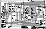
<strong>Xtreme</strong> <strong>Manufacturing</strong>XR945 ForkliftTable 7-41. Chassis Hose Kit (Current)Figure &Item No.Part No. Description Quantity Use On– 25010-001 Chassis hose kit – –7-41-1 12027-021 Suction 1 –7-41-2 12046-023 Return tank 1 –7-41-3 12000-060 Control valve L.S.-LS5 1 –7-41-4 12018-063 Control valve P-P2 1 –7-41-5 12048-061 Control valve return 1 –7-41-6 12022-014 Valve block P1-divider EF 1 –7-41-7 12026-041 Pump HP filter 1 –7-41-8 12010-130 Boom lower (A to BA) 1 –7-41-9 12018-130 Boom lift B-BB 1 –7-41-10 12010-130 Fork tilt A to FTA 1 –7-41-11 12010-130 Fork tilt B to FTB 1 –7-41-12 12010-192 Tele retract Hawe A 1 –7-41-13 12014-194 Tele extend Hawe B 1 –7-41-14 12041-206 Aux A and B 1 –7-41-15 12041-206 Aux A and B 1 –7-41-16 12006-066 Frame level Hawe A – FLA 1 –7-41-17 12006-098 Frame level Hawe B – front cylinder R 1 –7-41-18 12006-050 Frame level left to FLL 1 –7-41-19 12029-050 Cooler top to transmission 1 –7-41-20 12029-060 Cooler bottom to transmission 1 –7-41-21 12006-139 Rear axle lock-ALS 1 –7-41-22 12006-149 Rear axle lock-ALL 1 –7-41-23 12006-149 Rear axle lock-ALR 1 –7-41-24 12002-113 Brake rear (valve bottom port) 1 –7-41-25 12002-075 Brake front (valve top port) 1 –December 26, 2006 Preliminary Manual 7-88
<strong>Xtreme</strong> <strong>Manufacturing</strong>XR945 ForkliftTable 7-41. Chassis Hose Kit (Current)Figure &Item No.Part No. Description Quantity Use On7-41-26 12011-054 Steer return-T3 1 –7-41-27 12040-097 Rear steering (RSB) 1 –7-41-28 12047-120 Rear steering (RSA) 1 –7-41-29 12040-069 Front steering (steer valve-R cylinder) 1 –7-41-30 12040-043 Front steer (FSB-L cylinder) 1 –7-41-31 12010-063 Steer P-divider 1 –7-41-32 12006-043 Steer unit R-SVR 1 –7-41-33 12000-044 Steer LS-LS3 1 –7-41-34 12006-042 Brake valve return (pedal) 1 –7-41-35 12003-017 Priority valve L.S.-LS2 1 –7-41-36 12002-014 Priority valve T-T2 1 –7-41-37 12010-028 Charge valve P-priority CF 1 –7-41-38 12000-013 Charge valve P-priority 1 –7-41-39 12005-013 Accumulator supply B 1 –7-41-40 12005-015 Accumulator supply A 1 –7-41-41 12002-014 Brake charge valve LS-LS4 1 –7-41-42 12006-020 Charge valve T-T4 1 –7-41-43 12000-025 Pump LS-LS1 1 –7-41-44 12006-045 Brake valve supply 1 –7-41-45 12006-045 Brake valve supply 1 –7-41-46 12049-029 Pump case drain 1 –7-41-47 12002-052 Parking brake release 1 –7-41-48 12008-075 Fork tilt FTU-Lft. cylinder 1 –7-41-49 12008-075 Fork tilt FTD-Rt. cylinder 1 –7-41-50 12038-042 BU1-R cylinder port E 1 –7-41-51 12037-042 BD1-R cylinder port R 1 –December 26, 2006 Preliminary Manual 7-89
<strong>Xtreme</strong> <strong>Manufacturing</strong>XR945 ForkliftTable 7-41. Chassis Hose Kit (Current)Figure &Item No.Part No. Description Quantity Use On7-41-52 12038-042 BU2-L cylinder port E 1 –7-41-53 12037-042 BD2-L cylinder port E 1 –7-41-54 12003-017 Brake crossover 1 –7-41-55 12003-020 Brake crossover 2 –7-41-56 12008-120 OR1A, OB1B to outrigger cylinderports7-41-57 12008-120 OR2A, OR2B to outrigger cylinderports0 –0 –Refer to <strong>Section</strong> 1 for the definition of acronyms and abbreviations used in the Description Column.December 26, 2006 Preliminary Manual 7-90
<strong>Xtreme</strong> <strong>Manufacturing</strong>XR945 ForkliftTO BE SUPPLIEDFigure 7-42. Chassis Hose Kit (Version 1)December 26, 2006 Preliminary Manual 7-91
<strong>Xtreme</strong> <strong>Manufacturing</strong>XR945 ForkliftTable 7-42. Chassis Hose Kit (Version 1)Figure &Item No.Part No. Description Quantity Use On– 25010-000 Chassis hose kit – –7-42-1 12027-016 Suction 1 –7-42-2 12046-023 Return tank 1 –7-42-3 12000-060 Control valve L.S.-LS5 1 –7-42-4 12018-063 Control valve P-P2 1 –7-42-5 12048-061 Control valve return 1 –7-42-6 12022-015 Valve block P1-divider EF 1 –7-42-7 12026-041 Pump HP filter 1 –7-42-8 12010-130 Boom lower (A to BA) 1 –7-42-9 12018-130 Boom lift B-BB 1 –7-42-10 12010-130 Fork tilt A to FTA 1 –7-42-11 12010-130 Fork tilt B to FTB 1 –7-42-12 12010-192 Tele retract Hawe A 1 –7-42-13 12014-194 Tele extend Hawe B 1 –7-42-14 12041-206 Aux A and B 1 –7-42-15 12041-206 Aux A and B 1 –7-42-16 12006-066 Frame level Hawe A – FLA 1 –7-42-17 12006-098 Frame level Hawe B – front cylinder R 1 –7-42-18 12006-050 Frame level left to FLL 1 –7-42-19 12029-050 Cooler top to transmission 1 –7-42-20 12029-060 Cooler bottom to transmission 1 –7-42-21 12006-139 Rear axle lock-ALS 1 –7-42-22 12006-149 Rear axle lock-ALL 1 –7-42-23 12006-149 Rear axle lock-ALR 1 –7-42-24 12002-113 Brake rear (valve bottom port) 1 –7-42-25 12002-075 Brake front (valve top port) 1 –December 26, 2006 Preliminary Manual 7-92
<strong>Xtreme</strong> <strong>Manufacturing</strong>XR945 ForkliftTable 7-42. Chassis Hose Kit (Version 1)Figure &Item No.Part No. Description Quantity Use On7-42-26 12011-054 Steer return-T3 1 –7-42-27 12040-097 Rear steering (RSB) 1 –7-42-28 12047-120 Rear steering (RSA) 1 –7-42-29 12040-069 Front steering (steer valve-R cylinder) 1 –7-42-30 12040-043 Front steer (FSB-L cylinder) 1 –7-42-31 12010-063 Steer P-divider 1 –7-42-32 12006-043 Steer unit R-SVR 1 –7-42-33 12000-044 Steer LS-LS3 1 –7-42-34 12006-042 Brake valve return (pedal) 1 –7-42-35 12002-014 Priority valve L.S.-LS2 1 –7-42-36 12002-009 Priority valve T-T2 1 –7-42-37 12010-028 Charge valve P-priority CF 1 –7-42-38 12000-011 Charge valve to P.S. 1 –7-42-39 12005-013 Accumulator supply B 1 –7-42-40 12005-015 Accumulator supply A 1 –7-42-41 12002-014 Brake charge valve LS-LS4 1 –7-42-42 12006-020 Charge valve T-T4 1 –7-42-43 12000-011 Pump LS-LS1 1 –7-42-44 12006-045 Brake valve supply 1 –7-42-45 12006-045 Brake valve supply 1 –7-42-46 12049-029 Pump case drain 1 –Refer to <strong>Section</strong> 1 for the definition of acronyms and abbreviations used in the Description Column.December 26, 2006 Preliminary Manual 7-93
<strong>Xtreme</strong> <strong>Manufacturing</strong>XR945 ForkliftTHIS PAGE INTENTIONALLY LEFT BLANKDecember 26, 2006 Preliminary Manual 7-94