Download complete manual - pdf - Xtreme Manufacturing
Download complete manual - pdf - Xtreme Manufacturing
Download complete manual - pdf - Xtreme Manufacturing

Create successful ePaper yourself
Turn your PDF publications into a flip-book with our unique Google optimized e-Paper software.
Service ManualForward Reach ForkliftsXR620/621/842/1045/12451254/1267/1534/2050/3034<strong>Xtreme</strong> <strong>Manufacturing</strong>, LLC1415 West Bonanza RoadLas Vegas, NV 89106(702) 858-2404(702) 646-2196 (fax)www.xtrememanufacturing.comIMPORTANTRead and understand this <strong>manual</strong> beforeoperating or performing maintenance on these forklifts.Copyright © 2010 – <strong>Xtreme</strong> <strong>Manufacturing</strong>, LLCP/N 24933-000 Rev 01 – 05/10
Ask your supervisor to explain any operation, maintenance, or safety informationthat you do not fully understand.Untrained personnel can cause death or severe injury. Do not operate or performmaintenance on a forklift until you have read and understand:• The Operation and Safety Manual for the forklift.• Chapter 2 of this Service Manual.• The safety decals affixed to the forklift.• Your employer's applicable work rules regarding the safety,operation, and maintenance of the forklift.• Applicable federal, state, or local government regulations.Untrained personnel can cause death or severe injury. Do not operate or work on aforklift until you have been trained in the safe operation and maintenance of theforklift.– REPLACEMENT OF MANUALS –Contact <strong>Xtreme</strong> <strong>Manufacturing</strong>, LLC, to obtain replacement Operation and SafetyManuals, Owner’s Service Manuals, Service Manuals, or Illustrated Parts Catalogs.<strong>Xtreme</strong> <strong>Manufacturing</strong>, LLC1415 West Bonanza RoadLas Vegas, NV 89106(702) 851-3750xtrememanufacturing.com
List of Effective PagesXR620/621/842/1045/1245/1254/1267/1534/2050/3034List of Effective PagesThis <strong>manual</strong> consists of 277 pages as listed below:Front cover pageInside front cover pageTitle pagePages A through BPages i through xPages 1-1 through 1-32Pages 2-1 through 2-22Pages 3-1 through 3-6Pages 4-1 through 4-6Pages 5-1 through 5-34Pages 6-1 through 6-14Pages 7-1 through 7-8Pages 8-1 through 8-48Pages 9-1 through 9-22Pages 10-1 through 10-32Pages 11-1 through 11-6Pages 12-1 through 12-6Pages Index 1 through Index 6Pages A-1 through A-20Inside back cover pageBack cover pageCopyright © 2010 – <strong>Xtreme</strong> <strong>Manufacturing</strong> Co.Service Manual Rev 01 – 05/10 AP/N 24933-000
Service BulletinsXR620/621/842/1045/1245/1254/1267/1534/2050/3034Service BulletinsThe following Service Bulletins have been incorporated in this <strong>manual</strong>:Number Title CommentsService Manual Rev 01 – 05/10 BP/N 24933-000
Table of ContentsXR620/621/842/1045/1245/1254/1267/1534/2050/3034Table of ContentsPARA. TITLE PAGEList of Effective Pages...................................................................................................Service Bulletins............................................................................................................Table of Contents...........................................................................................................List of Illustrations ........................................................................................................List of Tables .................................................................................................................ABiviixSECTION 1 – GENERAL INFORMATION & SPECIFICATIONS....................................... 1-11-1 Scope of Manual ......................................................................................................... 1-11-2 Applicability ................................................................................................................. 1-11-3 Service Bulletins.......................................................................................................... 1-11-4 Related Technical Documentation.............................................................................. 1-21-5 Forklift Nomenclature.................................................................................................. 1-21-6 Component Data Plates.............................................................................................. 1-101-7 Lubricants and Fluids.................................................................................................. 1-141-8 Filters and Strainers.................................................................................................... 1-151-9 Forklift and Engine Specifications............................................................................... 1-161-10 Torque Wrench Use.................................................................................................... 1-261-11 Cap Screw Torque Values .......................................................................................... 1-27SECTION 2 – MAINTENANCE & OPERATION SAFETY ................................................. 2-12-1 General ....................................................................................................................... 2-12-2 Safety Signal Words.................................................................................................... 2-12-3 Notes........................................................................................................................... 2-12-4 Safety Symbols ........................................................................................................... 2-22-5 Lockout/Tagout Procedure.......................................................................................... 2-62-6 General Maintenance Precautions.............................................................................. 2-72-7 Viton Seals .................................................................................................................. 2-72-8 Using Compressed Air Safely ..................................................................................... 2-82-9 Battery Handling and Maintenance............................................................................. 2-82-10 Engine Operation and Maintenance ........................................................................... 2-102-11 Fuel Handling and Maintenance ................................................................................. 2-102-12 California Proposition 65 Warnings............................................................................. 2-112-13 Functional Tests.......................................................................................................... 2-112-14 Safe Operation Checklist ............................................................................................ 2-122-15 Functional Test Checklist............................................................................................ 2-132-16 Load Handling ............................................................................................................. 2-14Service Manual Rev 01 – 05/10 iP/N 24933-000
Table of ContentsXR620/621/842/1045/1245/1254/1267/1534/2050/3034Table of Contents – Cont.PARA. TITLE PAGE2-17 Picking Up a Load....................................................................................................... 2-162-18 Carrying a Load........................................................................................................... 2-162-19 Placing a Load ............................................................................................................ 2-162-20 Load Shift .................................................................................................................... 2-172-21 Proper Use of Forks.................................................................................................... 2-172-22 Prohibited Practices .................................................................................................... 2-172-23 Operator Hand Signals ............................................................................................... 2-172-24 Safety Decals .............................................................................................................. 2-24SECTION 3 – MAINTENANCE SCHEDULE .................................................................... 3-13-1 Establishing a Preventive Maintenance Program ....................................................... 3-13-2 Long-Interval Maintenance Requirements.................................................................. 3-5SECTION 4 – AXLE CYLINDER AND OUTRIGGER LUBRICATION................................ 4-14-1 General Maintenance Safety ...................................................................................... 4-14-2 Using a Grease Gun ................................................................................................... 4-24-3 Lubricate Axle Cylinders and Outriggers .................................................................... 4-3SECTION 5 – ENGINE ................................................................................................... 5-15-1 General Maintenance Safety ...................................................................................... 5-15-2 Check Engine Oil Level............................................................................................... 5-15-3 Check Engine Coolant Level....................................................................................... 5-35-4 Check for Oil and Coolant Leaks ................................................................................ 5-65-5 Check for Water in Fuel-Water Separator................................................................... 5-75-6 Empty Air Filter Dust Cup ........................................................................................... 5-95-7 Check Condition and Tension of Drive Belts .............................................................. 5-115-8 Change Engine Oil...................................................................................................... 5-115-9 Replace Oil Filters....................................................................................................... 5-145-10 Replace Fuel Filter...................................................................................................... 5-175-11 Check Specific Gravity of Coolant .............................................................................. 5-195-12 Drain and Flush Cooling System ................................................................................ 5-225-13 Replace Air Filter......................................................................................................... 5-245-14 Check Air Filter............................................................................................................ 5-255-15 Check Condition and Tension of Drive Belts .............................................................. 5-265-16 Check and Adjust Valve Tip Clearances..................................................................... 5-285-17 Check Engine Hoses and Connections ...................................................................... 5-30Service Manual Rev 01 – 05/10 iiP/N 24933-000
Table of ContentsXR620/621/842/1045/1245/1254/1267/1534/2050/3034Table of Contents – Cont.PARA. TITLE PAGE5-18 Check Radiator Hoses and Connections.................................................................... 5-315-19 Check Engine Wiring and Connections ...................................................................... 5-325-20 Check for Oil, Coolant, and Fuel Leaks ...................................................................... 5-33SECTION 6 – TRANSMISSION, AXLES, & DRIVE SHAFTS ........................................... 6-16-1 General Maintenance Safety ...................................................................................... 6-16-2 Using a Grease Gun ................................................................................................... 6-16-3 Lubricate Axle Grease Fittings.................................................................................... 6-26-4 Lubricate Drive Shafts................................................................................................. 6-46-5 Replace Transmission Filters and Fluids.................................................................... 6-66-6 Check Axle Oil Level................................................................................................... 6-86-7 Check Wheel End Oil Level ........................................................................................ 6-116-8 Drain and Fill Axle Wheel End .................................................................................... 6-13SECTION 7 – WHEELS & TIRES ................................................................................... 7-17-1 General Maintenance Safety ...................................................................................... 7-17-2 Check Wheel Lug Nut Torque..................................................................................... 7-17-3 Inspect Wheel/Tire Assembly ..................................................................................... 7-37-4 Replace Wheel/Tire Assembly.................................................................................... 7-47-5 Replace Tire................................................................................................................ 7-7SECTION 8 – HYDRAULIC SYSTEM.............................................................................. 8-18-1 General Maintenance Safety ...................................................................................... 8-18-2 Hydraulics Maintenance Safety and Precautions ....................................................... 8-18-3 Handling Hydraulic Fluid ............................................................................................. 8-28-4 Making Leak-Free Connections .................................................................................. 8-28-4-1 Hose and Tubing Installation Practices....................................................................... 8-28-4-2 Operating Conditions .................................................................................................. 8-28-4-3 Maintenance Practices................................................................................................ 8-38-5 Keeping the Hydraulic System Clean ......................................................................... 8-48-6 Check Hydraulic Fluid Level ....................................................................................... 8-68-7 Change Hydraulic Fluid............................................................................................... 8-88-8 Replace Suction Strainer ............................................................................................ 8-108-9 Clean Hydraulic Reservoir Strainer............................................................................. 8-128-10 Replace Air Breather................................................................................................... 8-148-11 Replace High-Pressure Filter...................................................................................... 8-168-12 Replace Return Line Filter .......................................................................................... 8-19Service Manual Rev 01 – 05/10 iiiP/N 24933-000
Table of ContentsXR620/621/842/1045/1245/1254/1267/1534/2050/3034List of Figures – Cont.FIGURE TITLE PAGE6-1 Axle Grease Fittings.................................................................................................... 6-36-2 Drive Shaft Grease Fittings......................................................................................... 6-56-3 Transmission Plugs and Filters................................................................................... 6-76-4 Axle Differential and Trumpet Fluid Levels ................................................................. 6-106-5 Axle Wheel End........................................................................................................... 6-127-1 Lug Nut Torque Check Sequence............................................................................... 7-27-2 Wheel/Tire Assembly .................................................................................................. 7-47-3 Wheel Lug Nut Tightening Sequence ......................................................................... 7-68-1 Making Leak-Free Connections .................................................................................. 8-38-2 Hydraulic Filtration System ......................................................................................... 8-58-3 Hydraulic Reservoir Sight Gauge................................................................................ 8-78-4 Hydraulic Reservoir Fill Cap ....................................................................................... 8-88-5 Hydraulic Reservoir..................................................................................................... 8-108-6 Hydraulic Reservoir Strainer ....................................................................................... 8-128-7 Air Breather ................................................................................................................. 8-158-8 Location of Hydraulic Filters........................................................................................ 8-178-9 High-Pressure Filter .................................................................................................... 8-188-10 Return Line Filter......................................................................................................... 8-208-11 Taking Hydraulic Fluid Sample ................................................................................... 8-238-12 Hose Installation Guidelines ....................................................................................... 8-268-13 Cartridge Valve Solenoid ............................................................................................ 8-308-14 Location of Hydraulic Components............................................................................. 8-328-15 Distribution Manifold Hose Connections – Model XR842........................................... 8-378-16 Distribution Manifold Hose Connections – Model XR1045......................................... 8-398-17 Distribution Manifold Hose Connections – Model XR1245......................................... 8-418-18 Distribution Manifold Hose Connections – Model XR1254......................................... 8-439-1 Battery and Cables...................................................................................................... 9-49-2 Battery Installation....................................................................................................... 9-79-3 Auxiliary Battery Installation........................................................................................ 9-129-4 Connecting Auxiliary Battery....................................................................................... 9-139-5 Electrical Center Relays and Fuses............................................................................ 9-149-6 Engine Relay Assembly .............................................................................................. 9-199-7 Correct Installation of Relays B through G, P/N 12068567 ........................................ 9-20Service Manual Rev 01 – 05/10 viiP/N 24933-000
Table of ContentsXR620/621/842/1045/1245/1254/1267/1534/2050/3034List of Figures – Cont.FIGURE TITLE PAGE9-8 Determining Fuse Condition ....................................................................................... 9-2210-1 Boom and Attachment Lubrication.............................................................................. 10-410-2 Boom Extend Chain Lubrication ................................................................................. 10-910-3 Chain Nomenclature ................................................................................................... 10-1010-4 Chain Damage Inspection........................................................................................... 10-1210-5 Chain Edge Wear Measurement................................................................................. 10-1410-6 Chain Elongation Measurement.................................................................................. 10-1610-7 Boom Chain Tension Adjustment ............................................................................... 10-1810-8 Boom Slide Blocks ...................................................................................................... 10-2010-9 Boom Roller Inspection............................................................................................... 10-2410-10 Location of Boom Rollers............................................................................................ 10-2510-11 Fork Nomenclature...................................................................................................... 10-2710-12 Measuring Fork Flank Wear........................................................................................ 10-3010-13 Boom Lift and Extend Cylinder Manual Lowering Valves........................................... 10-3411-1 Boom Angle Indicator.................................................................................................. 11-211-2 Frame Level Indicator ................................................................................................. 11-312-1 Tie-Down Point Locations ........................................................................................... 12-6Service Manual Rev 01 – 05/10 viiiP/N 24933-000
Table of ContentsXR620/621/842/1045/1245/1254/1267/1534/2050/3034List of TablesTABLE TITLE PAGE1-1 Related Technical Documentation.............................................................................. 1-11-2 Lubricants and Fluids.................................................................................................. 1-141-3 Filter and Strainer Part Numbers ................................................................................ 1-151-4 Model XR620/621 Specifications................................................................................ 1-171-5 Model XR842 Specifications ....................................................................................... 1-171-6 Model XR1045 Specifications ..................................................................................... 1-181-7 Model XR1245 Specifications ..................................................................................... 1-201-8 Model XR1254 Specifications ..................................................................................... 1-211-9 Model XR1267 Specifications ..................................................................................... 1-221-10 Model XR1534 Specifications ..................................................................................... 1-241-11 Model XR2050 Specifications ..................................................................................... 1-251-12 Model XR3034 Specifications ..................................................................................... 1-261-13 Engine Specifications.................................................................................................. 1-281-14 Tightening Torque Values – Cap Screws ................................................................... 1-302-1 Safety Symbols ........................................................................................................... 2-23-1 Preventive Maintenance – After Every 8 Hours of Operation..................................... 3-13-2 Preventive Maintenance – After First 50 Hours of Operation ..................................... 3-23-3 Preventive Maintenance – After Every 50 Hours of Operation................................... 3-23-4 Preventive Maintenance – After Every 250 Hours of Operation................................. 3-33-5 Preventive Maintenance – After Every 500 Hours of Operation................................. 3-33-6 Preventive Maintenance – After Every 1,000 Hours of Operation.............................. 3-43-7 Preventive Maintenance – After Every 2,000 Hours of Operation.............................. 3-53-8 Long-Interval Maintenance Requirements.................................................................. 3-55-1 Cylinder and Valve Numbers ...................................................................................... 5-297-1 Forklift Operating Weights .......................................................................................... 7-57-2 Wheel and Tire Specifications .................................................................................... 7-78-1 Hose Connector Torque Values.................................................................................. 8-278-2 Boom Isolation Manifold Valve Torque Values ........................................................... 8-458-3 Rear Axle Cylinder Valve Torque Values ................................................................... 8-458-4 Distribution Manifold Torque Values (XR842/1045) .................................................. 8-458-5 Distribution Manifold Torque Values (XR1245/1254) ................................................ 8-469-1 Electrical Center Relays.............................................................................................. 9-179-2 Electrical Center Fuses and Circuit Breaker............................................................... 9-17Service Manual Rev 01 – 05/10 ixP/N 24933-000
Table of ContentsXR620/621/842/1045/1245/1254/1267/1534/2050/3034List of Tables – Cont.TABLE TITLE PAGE9-3 Fuse Block Fuses........................................................................................................ 9-189-4 Engine Relay Assembly Relays and Fuse.................................................................. 9-1810-1 Fork Nomenclature...................................................................................................... 10-2712-1 Forklift Operating Weights .......................................................................................... 12-5Service Manual Rev 01 – 05/10 xP/N 24933-000
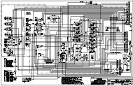
General Information & SpecificationsXR620/621/842/1045/1245/1254/1267/1534/2050/3034Section 1General Information & Specifications1-1 SCOPE OF MANUALThis <strong>manual</strong> provides operation and maintenance information and procedures intended for use by theowner and/or operator of the forklift. For detailed, specific operating instructions, refer to the applicableOperation and Safety Manual for the specific model forklift. For detailed maintenance and troubleshootinginformation and schematic diagrams, refer to the Service Manual.1-2 APPLICABILITYThis Owner's Service Manual applies to the following model rough-terrain, forward-reach forkliftsmanufactured by <strong>Xtreme</strong> <strong>Manufacturing</strong>:• XR620/621• XR842• XR1045• XR1245• XR1254• XR1267• XR1534• XR2050• XR30341-3 SERVICE BULLETINSService Bulletins are issued by <strong>Xtreme</strong> <strong>Manufacturing</strong>, LLC to help mechanics diagnose and repair forkliftproblems discovered during the manufacturing process or reported by owners and repair shops. Thereare two types of Service Bulletins:• Safety Service Bulletin: This type of bulletin is issued for safety problems that affect the safeoperation of the forklift. An example would be "Parking brake is weak."• Service Bulletin: This type of bulletin is issued for non-safety problems that affect the reliabilityor performance of the forklift of forklift subsystem. An example would be "Engine idles rough."Perform the following steps when you have received a service bulletin:• Carefully read and analyze the service bulletin.• Determine if the service bulletin applies to your forklift(s).Service Manual Rev 01 – 05/10 1-1P/N 24933-000
General Information & SpecificationsXR620/621/842/1045/1245/1254/1267/1534/2050/3034• Determine if you have the skills, tools, equipment, and personnel required to comply with theService Bulletin. If not, contact a reputable service center for assistance.• Comply with the inspection or maintenance procedure contained in the Service Bulletin.• For Safety Service Bulletins, <strong>complete</strong> the enclosed response form and return to:<strong>Xtreme</strong> <strong>Manufacturing</strong> Co.1415 West Bonanza RoadLas Vegas, NV 891061-4 RELATED TECHNICAL DOCUMENTATIONRefer to Table 1-1 for a listing of technical documentation related to the safety, operation, repair, andoverhaul of the forklifts.Table 1-1. Related Technical DocumentationItem Manufacturer/Agency Part No.Users Manual – 1100 Series EnginesModels RE, RF, RG, RH, RJ, RKPerkins Engines, Inc. TPD 1477Repair Manual – Transmission Model TLB24WDSpare Parts List – Transmission Model TLB2(Ref. 141166)Cararro SPACararro SPACA357151CA355311Repair Manual – Axle Model 26.28M Cararro SPA CA355038Spare Parts List – Axle Model 26.28M(Ref. 136534)Spare Parts List – Axle Model 26.28M(Ref. 142200)Service Manual – K3VL Swash-Plate TypeAxial Piston PumpMaintenance and Repair Instruction ManualDrive Axle Type 212Safety Standard for Rough Terrain ForkliftTrucksCararro SPACararro SPAKawasaki PrecisionMachinery of AmericaDANA ITALIA SpAAmerican Society ofMechanical EngineersCA355038CA35544303890327-EMO212S10ASME B56.6-20021-5 FORKLIFT NOMENCLATURERefer to Figure 1-1 for a depiction of forklift components and nomenclature. All forklifts are basically thesame except that models XR1245, XR1254, XR1267, and XR2050 are equipped with left and rightoutriggers.Service Manual Rev 01 – 05/10 1-2P/N 24933-000
General Information & SpecificationsXR620/621/842/1045/1245/1254/1267/1534/2050/3034Figure 1-1. Forklift Nomenclature (Sheet 1 of 4)Service Manual Rev 01 – 05/10 1-3P/N 24933-000
General Information & SpecificationsXR620/621/842/1045/1245/1254/1267/1534/2050/3034Figure 1-1. Forklift Nomenclature (Sheet 2 of 4)Service Manual Rev 01 – 05/10 1-4P/N 24933-000
General Information & SpecificationsXR620/621/842/1045/1245/1254/1267/1534/2050/3034FRAME SWAYCYLINDEROUTRIGGER PADFOAM- FILLEDTIREFigure 1-1. Forklift Nomenclature (Sheet 3 of 4)Service Manual Rev 01 – 05/10 1-5P/N 24933-000
General Information & SpecificationsXR620/621/842/1045/1245/1254/1267/1534/2050/3034Figure 1-1. Forklift Nomenclature (Sheet 4 of 4)Service Manual Rev 01 – 05/10 1-6P/N 24933-000
General Information & SpecificationsXR620/621/842/1045/1245/1254/1267/1534/2050/3034Figure 1-2. Forklift CoversService Manual Rev 01 – 05/10 1-7P/N 24933-000
General Information & SpecificationsXR620/621/842/1045/1245/1254/1267/1534/2050/3034Figure 1-3. Forklift CabService Manual Rev 01 – 05/10 1-8P/N 24933-000
General Information & SpecificationsXR620/621/842/1045/1245/1254/1267/1534/2050/3034LEGEND:1. PARKING BRAKE SWITCH 11. RIGHT OUTRIGGER DEPLOYED INDICATOR2. PARKING BRAKE INDICATOR 12. RIGHT OUTRIGGER DEPLOY SWITCH3. LOAD CAPACITY CHART HOLDER 13. LEFT OUTRIGGER DEPLOYED INDICATOR4. HYDRAULIC OIL TEMPERATURE INDICATOR 14. LEFT OUTRIGGER DEPLOY SWITCH5. LOW BRAKE PRESSURE INDICATOR 15. DECLUTCH SWITCH6. REAR AXLE LOCKED INDICATOR 16. DECLUTCH INDICATOR7. VOLTS GAUGE 17. STEERING SELECT SWITCH8. FUEL GAUGE 18. REAR AXLE CENTERED INDICATOR9. OIL PRESSURE GAUGE 19. WORKLIGHT SWITCH10. COOLANT GAUGE 20. HOUR METERFigure 1-4. Front Control PanelService Manual Rev 01 – 05/10 1-9P/N 24933-000
General Information & SpecificationsXR620/621/842/1045/1245/1254/1267/1534/2050/3034Figure 1-5. Side Control Console1-6 COMPONENT DATA PLATESRefer to Figure 1-6 for the location of major component data plates.Service Manual Rev 01 – 05/10 1-10P/N 24933-000
General Information & SpecificationsXR620/621/842/1045/1245/1254/1267/1534/2050/3034CHASSISENGINEFigure 1-6. Location of Chassis and Engine Data PlatesService Manual Rev 01 – 05/10 1-11P/N 24933-000
General Information & SpecificationsXR620/621/842/1045/1245/1254/1267/1534/2050/3034CARRARO TRANSMISSION INSTALLED IN MODEL XR1045/1245/1254/1534 FORKLIFTSDANA TRANSMISSION INSTALLED IN MODEL XR842/1267/2050/3034 FORKLIFTSFigure 1-7. Location of Transmission Data PlatesService Manual Rev 01 – 05/10 1-12P/N 24933-000
General Information & SpecificationsXR620/621/842/1045/1245/1254/1267/1534/2050/3034CARRARO AXLES INSTALLED IN MODEL XR620/621/1045/1245/1254/1534 FORKLIFTSDANA AXLES INSTALLED IN MODEL XR842/1267 FORKLIFTSKESSLER AXLES INSTALLED IN MODEL XR2050/3034 FORKLIFTSFigure 1-8. Location of Axle Data PlatesService Manual Rev 01 – 05/10 1-13P/N 24933-000
General Information & SpecificationsXR620/621/842/1045/1245/1254/1267/1534/2050/30341-7 LUBRICANTS AND FLUIDSThe lubricants and fluids listed in Table 1-2 are required for forklift lubrication and servicing.Table 1-2. Lubricants and FluidsItemSpecificationFuelASTM #2 diesel fuel with minimum Cetane rating of 40 forbetter fuel economy and performance under most operatingconditions.Use standard #2 diesel fuel for operating at temperaturesabove 32°F.Use a blend of #1 and #2 diesel fuel ("winterized" #2 diesel)for operating at temperatures below 32°F.Fuels with Cetane ratings higher than 40 may be required inhigher altitudes or an extremely low temperature climate toprevent misfiring and excessive smoke.Engine oil 15W-40 API CG4 or ACEA E3 (good to -4º F)Engine coolantTransmission fluidAxle oil (842)Service brake fluid (842)Axle oil(620/621/1045/1245/1254/1534/20503034)Hydraulic fluidGreaseChain lubricants50% ethylene glycol / 50% water mixtureDexron IIITRACTELF SF3Dexron II or Dexron IIIThere are two different axles that may be installed onModel XR620/621/1045/1245/1254/1534 forklifts. Theseaxles have different lubrication requirements. One axlerequires SAE 80W-90 EP API GL4 Oil; the other axlerequires SAE 80W-90 EP API GL5 Oil. Always check theaxle data plate to determine the correct lubricant andquantity required.Dexron III (AW46 for older units with clear fluid)Extreme pressure NLGI #2 or betterZep 45 Penetrating LubricantLPS 3® Heavy-Duty InhibitorLubriplate Chain & Cable FluidService Manual Rev 01 – 05/10 1-14P/N 24933-000
General Information & SpecificationsXR620/621/842/1045/1245/1254/1267/1534/2050/30341-9 FORKLIFT AND ENGINE SPECIFICATIONSRefer to Tables 1-4 through 1-7 for forklift specifications. Engine specifications are provided in Table 1-8.Table 1-4. Model XR620/621 SpecificationsItemSpecificationPerformanceLift capacity6,000 lbsLift height 21'Forward reach 12' 9"Frame levelingOperating weight6° left, 6° right12,700 lbsPower TrainEnginePerkins dieselHorsepower 84Fuel capacityTransmission24 galCarraroSpeeds 1AxleService brakesParking brakeTiresCarraroInboard, wet diskSpring-actuated, hydraulically-released12 x 16.5 E3 / G2Hydraulic SystemPumpMaximum flow rate at rated engine speedMaximum pressureReservoir capacityMarzocchi, fixed displacement, 44 cc27 gallons per minute3,500 psi22 gallonsService Manual Rev 01 – 05/10 1-16P/N 24933-000
General Information & SpecificationsXR620/621/842/1045/1245/1254/1267/1534/2050/3034Table 1-4. Model XR620/621 Forklift – Cont.ItemSpecificationDimensionsLength to fork face 15'Width 74"Height 7' 6"Wheel base 94”Ground clearance 10"Turning radius4' 6” (inside)Table 1-5. Model XR842 SpecificationsItemSpecificationPerformanceLift capacity8,000 lbsLift height 41' 5"Forward reach 28' 10"Frame levelingOperating weight11° left, 11° right26,850 lbsPower TrainEnginePerkins dieselHorsepower 99Fuel capacityTransmission48 galDanaSpeeds 3AxleDana/SpicerService Manual Rev 01 – 05/10 1-17P/N 24933-000
General Information & SpecificationsXR620/621/842/1045/1245/1254/1267/1534/2050/3034Table 1-5. Model XR842 Specifications – Cont.ItemSpecificationService brakesParking brakeTiresInboard, wet diskSpring-actuated, hydraulically-releasedFoam filled, 13.0 x 24 E3Hydraulic SystemPumpMaximum flow rate at rated engine speedMaximum pressureReservoir capacityKawasaki, variable displacement axial piston60 cc39 gallons per minute3,500 psi45 gallonsDimensionsLength to fork face 20' 11"Width 8' 5"Height 7' 11"Wheel base 10'Ground clearance 16.5"Turning radius12' (inside)Table 1-6. Model XR1045 SpecificationsItemSpecificationPerformanceLift capacity10,000 lbsLift height 44' 8"Forward reach 30' 4"Frame levelingOperating weight11° left, 11° right27,130 lbsService Manual Rev 01 – 05/10 1-18P/N 24933-000
General Information & SpecificationsXR620/621/842/1045/1245/1254/1267/1534/2050/3034Table 1-6. Model XR1045 Specifications – Cont.ItemSpecificationPower TrainEnginePerkins dieselHorsepower 108Fuel capacityTransmission48 gallonsCarraroSpeeds 4AxleService brakesParking brakeTiresCarraroInboard, wet diskSpring-actuated, hydraulically-releasedFoam filled, 13.0 x 24 E3Hydraulic SystemPumpMaximum flow rate at rated engine speedMaximum pressureReservoir capacityKawasaki, variable displacement axial piston(80 cc)49 gallons per minute3,500 psi45 gallonsDimensionsLength to fork face 21' 9"Width 8' 5"Height 7' 11"Wheel base 10'Ground clearance 16.5"Turning radius12' (inside)Service Manual Rev 01 – 05/10 1-19P/N 24933-000
General Information & SpecificationsXR620/621/842/1045/1245/1254/1267/1534/2050/3034Table 1-7. Model XR1245 SpecificationsItemSpecificationPerformanceLift capacity12,000 lbsLift height 44' 8"Forward reach 30' 4"Frame levelingOperating weight11° left, 11° right32,930 lbsPower TrainEnginePerkins dieselHorsepower 122Fuel capacityTransmission48 galCarraroSpeeds 4AxleService brakesParking brakeTiresCarraroInboard, wet diskSpring-actuated, hydraulically-releasedFoam filled, 15.5 x 25 E3Hydraulic SystemPumpMaximum flow rate at rated engine speedMaximum pressureReservoir capacityKawasaki, variable displacement axial piston80 cc49 gallons per minute3,500 psi45 gallonsService Manual Rev 01 – 05/10 1-20P/N 24933-000
General Information & SpecificationsXR620/621/842/1045/1245/1254/1267/1534/2050/3034Table 1-7. Model XR1245 Specifications – Cont.ItemSpecificationDimensionsLength to fork face 22' 3"Width 8' 5"Height 7' 11"Wheel base 10' 4"Ground clearance 16.5"Turning radius12' 2" (inside)Table 1-8. Model XR1254 SpecificationsItemSpecificationPerformanceLift capacity12,000 lbsLift height 53' 6"Forward reach 38'Frame levelingOperating weight11° left, 11° right35,700 lbsPower TrainEnginePerkins dieselHorsepower 122Fuel capacityTransmission72 gallonsCarraroSpeeds 4AxleCarraroService Manual Rev 01 – 05/10 1-21P/N 24933-000
General Information & SpecificationsXR620/621/842/1045/1245/1254/1267/1534/2050/3034Table 1-8. Model XR1254 Specifications – Cont.ItemSpecificationService brakesParking brakeTiresInboard, wet diskSpring-actuated, hydraulically-releasedFoam filled, 15.5 x 25 E3Hydraulic SystemPumpMaximum flow rate at rated engine speedMaximum pressureReservoir capacityKawasaki, variable displacement axial piston80 cc49 gallons per minute3,500 psi45 gallonsDimensionsLength to fork face 25'Width 8' 5"Height 7' 11"Wheel base 11' 9"Ground clearance 16.5"Turning radius14' (inside)Table 1-9. Model XR1267 SpecificationsItemSpecificationPerformanceLift capacity12,000 lbsLift height 67’Forward reach 53' 8"Frame levelingOperating weight8° left, 8° right46,300 lbsService Manual Rev 01 – 05/10 1-22P/N 24933-000
General Information & SpecificationsXR620/621/842/1045/1245/1254/1267/1534/2050/3034Table 1-9. Model XR1267 Specifications – Cont.ItemSpecificationPower TrainEnginePerkins dieselHorsepower 130Fuel capacityTransmission72 gallonsDanaSpeeds 3AxleService brakesParking brakeTiresDana/SpicerInboard, wet diskSpring-actuated, hydraulically-releasedFoam filled, 17.5 x 25 E3Hydraulic SystemPumpMaximum flow rate at rated engine speedMaximum pressureReservoir capacityKawasaki, variable displacement axial piston(80 cc)49 gallons per minute4,000 psi45 gallonsDimensionsLength to fork face 26' 6"Width 102"Height 8' 11"Wheel base 147”Ground clearance 15"Turning radius15' 10” (inside)Service Manual Rev 01 – 05/10 1-23P/N 24933-000
General Information & SpecificationsXR620/621/842/1045/1245/1254/1267/1534/2050/3034Table 1-10. Model XR1534 SpecificationsItemSpecificationPerformanceLift capacity15,000 lbsLift height 34'Forward reach 17'Frame levelingOperating weight11° left, 11° right29,000 lbsPower TrainEnginePerkins dieselHorsepower 122Fuel capacityTransmission48 galCarraroSpeeds 4AxleService brakesParking brakeTiresCarraroInboard, wet diskSpring-actuated, hydraulically-releasedFoam filled, 15.5 x 25 E3Hydraulic SystemPumpMaximum flow rate at rated engine speedMaximum pressureReservoir capacityKawasaki, variable displacement axial piston80 cc49 gallons per minute4,300 psi45 gallonsService Manual Rev 01 – 05/10 1-24P/N 24933-000
General Information & SpecificationsXR620/621/842/1045/1245/1254/1267/1534/2050/3034Table 1-10. Model XR1534 Specifications – Cont.ItemSpecificationDimensionsLength to fork face 21' 6"Width 101"Height 7' 11"Wheel base 124"Ground clearance 16.5"Turning radius12' 2" (inside)Table 1-11. Model XR2050 SpecificationsItemSpecificationPerformanceLift capacity20,000 lbsLift height 50'Forward reach 36'Frame levelingOperating weight8° left, 8° right48,750 lbsPower TrainEnginePerkins dieselHorsepower 130Fuel capacityTransmission72 galDanaSpeeds 3AxleService brakesParking brakeKesslerInboard, wet diskSpring-actuated, hydraulically-releasedService Manual Rev 01 – 05/10 1-25P/N 24933-000
General Information & SpecificationsXR620/621/842/1045/1245/1254/1267/1534/2050/3034Table 1-11. Model XR2050 Specifications – Cont.ItemSpecificationTiresFoam filled, 16 x 25 E3Hydraulic SystemPumpMaximum flow rate at rated engine speedMaximum pressureReservoir capacityKawasaki, variable displacement axial piston80 cc49 gallons per minute4,000 psi45 gallonsDimensionsLength to fork face 27'Width 102"Height 9' 6"Wheel base 148"Ground clearance 15"Turning radius16' 8" (inside)Table 1-12. Model XR3034 SpecificationsItemSpecificationPerformanceLift capacity30,000 lbsLift height 34'Forward reach 17' 6”Frame levelingOperating weight8° left, 8° right47,850 lbsPower TrainEnginePerkins dieselHorsepower 130Service Manual Rev 01 – 05/10 1-26P/N 24933-000
General Information & SpecificationsXR620/621/842/1045/1245/1254/1267/1534/2050/3034Table 1-12. Model XR3034 Specifications – Cont.ItemSpecificationFuel capacityTransmission72 galDanaSpeeds 3AxleService brakesParking brakeTiresKesslerInboard, wet diskSpring-actuated, hydraulically-releasedFoam filled, 16 x 25 E3Hydraulic SystemPumpMaximum flow rate at rated engine speedMaximum pressureReservoir capacityKawasaki, variable displacement axial piston80 cc49 gallons per minute4,500 psi45 gallonsDimensionsLength to fork face 23' 4"Width 102"Height 9' 6"Wheel base 148"Ground clearance 15"Turning radius16' 8" (inside)Service Manual Rev 01 – 05/10 1-27P/N 24933-000
General Information & SpecificationsXR620/621/842/1045/1245/1254/1267/1534/2050/3034Table 1-13. Engine SpecificationsItemSpecificationManufacturerPerkins Engines, Inc.Model 1104Emission standardTier 2 or Tier 3 (depending on application)Number of cylinders 4Cylinder arrangementCycleHorsepowerDirection of rotationAir induction system (aspiration)ItemCombustion systemInlineFour strokeModel 620/621: 84 hp @ 2,300 rpmModel 842:Model 1045:Model 1245:Model 1254:Model 1267:Model 1534:Model 2050:Model 3034:Clockwise (from front)99 hp @ 2,300 rpm108 hp @ 2,300 rpm122 hp @ 2,300 rpm122 hp @ 2,300 rpm130 hp @ 2,300 rpm122 hp @ 2,300 rpm130 hp @ 2,300 rpm130 hp @ 2,300 rpmTurbocharged(charge is cooled on 1045/1245/1254/1267/1534/2050/3034)Direct injectionSpecificationFiring order 1 - 3 - 2 - 4Low idleHigh idle1,000 rpm2,300 rpmValve tip clearances (cold engine) Intake: 0.008 in. (0.20 mm)Exhaust: 0.018 in. (0.45 mm)Lubricating oil pressure 1VoltageStarting aid43 lbf/in. (300 kpa, 3.0 kg/cm)12 voltsGlow plug heated combustion chamber1 Minimum pressure at maximum engine speed and normal engine temperature.Service Manual Rev 01 – 05/10 1-28P/N 24933-000
General Information & SpecificationsXR620/621/842/1045/1245/1254/1267/1534/2050/30341-10 TORQUE WRENCH USENumerous forklift components require that the attaching hardware be torqued to a specific value duringcomponent installation. A torque wrench is required to tighten bolts, nuts, and screws. Listed below arestandard procedures and precautions to observe when using a torque wrench:• Ensure that the torque wrench has been calibrated.• Always work with clean fastener threads that are free of corrosion.• If an installation procedure specifies a thread lubricant, use it.• Observe the torque sequence instructions provided in installation procedures.• Pull the torque wrench in a clockwise direction, using a steady, smooth motion. A fast or jerkytightening motion will result in an improperly torqued fastener.• Avoid over-tightening a fastener with a conventional wrench or impact wrench before applyinga torque wrench to the fastener.• Do not use the torque wrench to apply greater amounts of torque than its rated capacity.• Never use a torque wrench as a hammer or to pry apart parts.• Never use a torque wrench as a conventional wrench.• Do not apply a torque wrench to a nut that has been tightened. Back off the nut one turn with aconventional wrench and retighten it to the correct torque with a torque wrench.• Do not use the torque wrench to break loose bolts that have been previously tightened.• Avoid dropping a torque wrench. If a wrench is dropped, check its accuracy on a torque tester.• When using a torque wrench, do not over-torque the fastener by applying torque past therelease point. Learn the feel of the torque wrench release rather than relying on the sound thewrench makes.• When not in use, set the torque wrench to its lowest torque value. But DO NOT set the wrenchto a value below the lowest torque value.When the torque wrench is in frequent or continuous use, periodically check the wrench's calibrationaccuracy.1-11 CAP SCREW TORQUE VALUESRefer to Table 1-9 for a listing of recommended assembly torque values for Society of AutomotiveEngineers (SAE) Grade 5 and Grade 8 caps crews. The following criteria apply to the determination oftorque values:• All torque values are based on the use of through-hardened flat washers under the bolt head andnut or only under the bolt head in a tapped hole application. This provides a uniform, hard, smoothbearing surface.• Torque values are calculated at 75% of proof load. This calculation method provides a safety factor.• All dry torque values are given for the as received condition, such as plated hex head cap screws.Ensure that damaged cap screws are replaced with SAE grade 8 cap screws from a reputablemanufacturer/vendor. Refer to Figure 1-9 for a diagram depicting the cap screw head markings of a grade8 cap screw or bolt.Service Manual Rev 01 – 05/10 1-29P/N 24933-000
General Information & SpecificationsXR620/621/842/1045/1245/1254/1267/1534/2050/3034Table 1-12. Tightening Torque Values – Cap ScrewsNominal Diameter (Inches)and Threads-Per-InchSAE Grade 5 Cap ScrewsTightening Torque (Ft-Lbs)SAE Grade 8 Cap Screws1/4 20 8 (96) a 12 (144) a1/4 28 10 (120) a 14 (170) a5/16 18 17 (205) a 25 (300) a5/16 24 19 (230) a 27 (325) a3/8 16 31 (370) a 44 (530) a3/8 24 35 (420) a 49 (590) a7/16 14 49 (590) a 707/16 20 56 (670) a 781/2 13 76 1081/2 20 86 1209/16 12 110 154Table 1-12. Tightening Torque Values – Cap Screws – Cont.Nominal Diameter (Inches)and Threads-Per-InchSAE Grade 5 Cap ScrewsTightening Torque (Ft-Lbs)SAE Grade 8 Cap Screws9/16 18 122 1725/8 11 150 2125/8 18 170 2403/4 10 265 3753/4 16 295 4207/8 9 430 6067/8 14 475 6741 8 645 9091 14 723 10201-1/8 7 794 12871-1/8 12 890 1444Service Manual Rev 01 – 05/10 1-30P/N 24933-000
General Information & SpecificationsXR620/621/842/1045/1245/1254/1267/1534/2050/30341-1/4 7 1120 18171-1/4 12 1241 20131-3/8 6 1469 23821-3/8 12 1672 27121-1/2 6 1949 31611-1/2 12 2194 3557aInstallation with an inch-pound torque wrench is recommended. The inch-pound torque value is listed in parentheses.SAE GRADE 8BOLT MARKINGSFigure 1-9. SAE Grade 8 Bolt MarkingsService Manual Rev 01 – 05/10 1-31P/N 24933-000
General Information & SpecificationsXR620/621/842/1045/1245/1254/1267/1534/2050/3034THIS PAGE INTENTIONALLY LEFT BLANKService Manual Rev 01 – 05/10 1-32P/N 24933-000
Maintenance & Operation SafetyXR620/621/842/1045/1245/1254/1267/1534/2050/3034Section 2Maintenance & Operation Safety2-1 GENERALOperating and maintaining a rough-terrain, forward-reach forklift can be a very safe endeavor, or a verydangerous endeavor. The U.S. Government, private industry, and <strong>Xtreme</strong> <strong>Manufacturing</strong> have extendeda great deal of time, effort, and money in making the operator’s and mechanic’s workplace safe. To helpaccomplish that goal, standardized safety signal words and symbols have been developed andincorporated in this <strong>manual</strong>.2-2 SAFETY SIGNAL WORDSSafety signal words are the word or words that call attention to a hazard and designate a degree or levelof hazard seriousness. The signal words used in this <strong>manual</strong> are DANGER, WARNING, and CAUTION.The word DANGER in a red box indicates an imminently hazardous situation which, if notavoided, will result in death or serious injury.The word WARNING in an orange box indicates a potentially hazardous situation which,if not avoided, could result in death or serious injury.The word CAUTION in a yellow box, when used with the safety alert symbol, indicates apotentially hazardous situation which, if not avoided, could result in minor or moderateinjury.The word CAUTION in a yellow box, when used without the safety alert symbol, indicatesa potentially hazardous situation which, if not avoided, may result in property damage.2-3 NOTESNotes are used to highlight important maintenance information that is provided to facilitatetroubleshooting and repair actions. Notes are not used to convey any type of danger or safetyinformation. Notes may appear before or after the affected text or illustration and appear as follows:NOTE: Do not over-tighten the chain.Service Manual Rev 01 – 05/10 2-1P/N 24933-000
Maintenance & Operation SafetyXR620/621/842/1045/1245/1254/1267/1534/2050/30342-4 SAFETY SYMBOLSSafety symbols are used in the <strong>manual</strong> to warn of hazardous situations. <strong>Xtreme</strong> <strong>Manufacturing</strong> providesthese symbols in an attempt to inform all mechanics and operators, regardless of reading and languageskills, of as many potential hazards as possible. These symbols cover many, but not all, potential dangersand hazards associated with operating the forklift. Make safety a high priority while operating the forklift.Learn and follow all safety messages in this <strong>manual</strong> and on the forklift labels to prevent death, injury, orequipment damage. Refer to Table 2-1 for a <strong>complete</strong> listing of safety symbols and their meaning.Table 2-1. Safety SymbolsSymbol Meaning Symbol MeaningGENERAL SAFETYALERT SYMBOLDO NOT OPERATE!VEHICLE DOWN FORSAFETY ORMAINTENANCEPERSONALPROTECTIVEEQUIPMENTWEAR EARPROTECTIONPERSONALPROTECTIVEEQUIPMENTWEAR SAFETYGLASSESPERSONALPROTECTIVEEQUIPMENTWEAR HARD HATPERSONALPROTECTIVEEQUIPMENTWEAR SAFETY GLOVESPERSONAL PROTECTIVEEQUIPMENTWEAR SAFETY BOOTSPERFORM OPERATORINSPECTION BEFORESTARTING THIS VEHICLEKNOW FIRSTINSTRUCTIONS AND/ORFIRST AID LOCATIONS ONJOBSITEREAD MAINTENANCEMANUAL BEFOREWORKING ON THISVEHICLEREAD THE OPERATORMANUAL BEFOREOPERATING THIS VEHICLEREAD MATERIAL SAFETYDATA SHEETS (MSDS)FOR CHEMICALS ANDFLUIDSService Manual Rev 01 – 05/10 2-2P/N 24933-000
Maintenance & Operation SafetyXR620/621/842/1045/1245/1254/1267/1534/2050/3034Table 2-1. Safety Symbols – Cont.Symbol Meaning Symbol MeaningWARNING!HOT SURFACE. KEEPHANDS AWAYWARNING!HOT OIL. DO NOT OPENUNLESS CAP IS COOL TOTOUCH.WARNING!USE BOARD ORCARDBOARD TO CHECKFOR HYDRAULIC LEAKS.DO NOT USE YOUR HANDWARNING!HYDRAULIC OIL UNDERPRESSUREHYDRAULIC SYSTEMUNDER PRESSUREATTACH DANGER TAGWARNING!KEEP HANDS A SAFEDISTANCE FROMROTATING BELTSWARNING!ROTATING FAN BLADESCAN CUTWARNING!KEEP HANDS A SAFEDISTANCE FROMROTATING FAN BLADESWARNING!ROTATING BELTS CANCUT OR ENTANGLEKEEP FLAMES ANDIGNITION SOURCES AWAYNO SMOKINGKEEP LIT CIGARETTESAWAYPINCH POINT FOR HANDSPINCH POINTS FOR BODYService Manual Rev 01 – 05/10 2-3P/N 24933-000
Maintenance & Operation SafetyXR620/621/842/1045/1245/1254/1267/1534/2050/3034Table 2-1. Safety Symbols – Cont.Symbol Meaning Symbol MeaningLEAD-ACID BATTERIESDEVELOP EXPLOSIVEGASESBATTERYWARNING!EXPLOSION HAZARDHAVE ADEQUATEVENTILATION IFOPERATING THIS VEHICLEIN AN ENCLOSED SPACEMAKE SURE ALL SAFETYLABELS ARE ATTACHEDAND LEGIBLEREPLACE WORN ANDILLEGIBLE SAFETYLABELS AND LABELSDO NOT USE ETHER AS ASTARTING FLUIDDO NOT OPERATE IFUSING ALCOHOL, DRUGS,OR MEDICATIONUSE 3-POINT CONTACTMOUNTING ANDDISMOUNTING FORKLIFTDO NOT JUMP WHILEDISMOUNTING FORKLIFTFASTEN SEAT BELTDO NOT USE AS APERSONNEL CARRIERDO NOT ALLOW RIDERSON FORKLIFT FRAME ORFENDERSDO NOT ALLOW RIDERSON OR IN OPERATOR CABService Manual Rev 01 – 05/10 2-4P/N 24933-000
Maintenance & Operation SafetyXR620/621/842/1045/1245/1254/1267/1534/2050/3034Table 2-1. Safety Symbols – Cont.Symbol Meaning Symbol MeaningFALLING OFF OFATTACHMENT CANRESULT IN DEATH ORSERIOUS INJURYSET PARKING BRAKE TOONENGAGE PARKING BREAKSET PARKING BRAKE TOOFFDISENGAGE PARKINGBRAKEWARNING!VEHICLE ROLL AWAY CANCAUSE DEATH ORSERIOUS INJURYWARNING!VEHICLE TIP OVER CANCAUSE DEATH ORSERIOUS INJURYDO NOT JUMP!IF VEHICLE TIPS, KEEPSEAT BELT ON ANDBRACE YOURSELFDO NOT TRAVEL WITHBOOM RAISEDDO NOT RAISE BOOMWHILE TRAVELING ON ASLOPETIP OVER HAZARD,ESPECIALLY TRAVELINGUP A SLOPE WITHOUT ALOADWARNINGELECTROCUTION CANCAUSE DEATH ORSERIOUS INJURYDANGER!KEEP A SAFE DISTANCEFROM ELECTRICAL LINESDO NOT ALLOW ANYONEUNDER A RAISED LOADService Manual Rev 01 – 05/10 2-5P/N 24933-000
Maintenance & Operation SafetyXR620/621/842/1045/1245/1254/1267/1534/2050/30342-5 LOCKOUT/TAGOUT PROCEDUREPerform the following procedure to lockout and tagout the forklift. This procedure, requiring a lock, dangertags, and a condition tag is to be used whenever the forklift is unsafe for operation or maintenance.REMOVING FORKLIFT FROM SERVICE1. Attach danger tags (Figure 2-1) to steering wheel and ignition key.2. Pull back on both battery cover T-handles until they release from holders (Figure 1-2).3. Lower battery cover.4. Set battery disconnect switch (Figure 2-2) to OFF.5. Lock battery disconnect switch.If forklift is unsafe for operation or maintenance, the defect or defects must beclearly documented and posted in a conspicuous place on the forklift. Failure tocomply may result in death, serious injury, and property damage.6. Attach condition tag (Figure 2-1) to battery disconnect switch. Condition tag should clearly state whyforklift is unsafe for operation or maintenance.RETURNING FORKLIFT TO SERVICEWhen the forklift has been repaired and made safe for operation and maintenance, perform the followingprocedure to return the forklift to service:1. Remove lock and condition tag from battery disconnect switch.2. Raise and secure battery cover.3. Remove danger tags from steering wheel and ignition key.NOTE:SAMPLE DANGER TAGS ARE PROVIDED IN THEAPPENDIX, MAINTENANCE FORMS & SAFETY TAGS.Figure 2-1. Danger and Condition TagsService Manual Rev 01 – 05/10 2-6P/N 24933-000
Maintenance & Operation SafetyXR620/621/842/1045/1245/1254/1267/1534/2050/3034Figure 2-2. Battery Disconnect Switch2-6 GENERAL MAINTENANCE PRECAUTIONS• Do not make adjustments that you do not understand.• Do not permit loose clothing or long hair near moving parts.• Use extreme care if emergency repairs must be made in adverse conditions.• Do not wear clothing which is contaminated by lubricating oil. Do not put materialwhich is contaminated with oil into the pockets of clothing.2-7 VITON SEALSViton is used by many manufacturers and is a safe material under normal conditions of operation. Someseals used in the engine and in components fitted to the engine are made of Viton.If Viton is burned, a product of this burnt material is an acid which is extremely dangerous.Never allow this burnt material to come into contact with the skin or with the eyes. If it isService Manual Rev 01 – 05/10 2-7P/N 24933-000
Maintenance & Operation SafetyXR620/621/842/1045/1245/1254/1267/1534/2050/3034necessary to come into contact with components which have been burnt, ensure that theprecautions which follow are used:• Ensure that the components have cooled.• Use neoprene gloves and discard the gloves safely after use.• Wash the area with calcium hydroxide solution and then with clean water.• Disposal of components and gloves which are contaminated must be inaccordance with local regulations.If there is contamination of the skin or eyes, wash the affected area with a continuous supply ofclean water or with calcium hydroxide solution for 15-60 minutes. Obtain immediate medicalattention.2-8 USING COMPRESSED AIR SAFELY• Always wear goggles, face shield, or other eye protection when usingcompressed air to clean equipment.• Do not allow compressed air to contact your skin. If compressed air enters yourskin, obtain medical help immediately.• Do not use compressed air to clean dust and dirt from clothing.• Ensure that the nozzle is equipped with a chip guard.• Never use compressed air that exceeds 30 psi.• Hoses should not be strung across floors or aisles where they are liable tocause a trip hazard. When possible, air supply hoses should be suspendedoverhead.• Hose ends must be secured to prevent whipping if an accidental cut or breakoccurs.• Never point pneumatic tools at a person.• Do not use compressed air to dry roller bearings. The air can cause the bearingto rotate at an extremely high speed and disintegrate.• Turn off the air supply before disconnecting a pneumatic tool (unless equippedwith a quick-disconnect coupling).2-9 BATTERY HANDLING AND MAINTENANCE• If contact with battery acid occurs, administer the following first aid treatment toself or others:– External contact – Flush with water.Service Manual Rev 01 – 05/10 2-8P/N 24933-000
Maintenance & Operation SafetyXR620/621/842/1045/1245/1254/1267/1534/2050/3034– Eyes – Flush with water for at least 15 minutes. Get medical attentionimmediately.– Internal contact – Drink large quantities of water. Follow with Milk ofMagnesia, beaten egg, or vegetable oil. Get medical attention immediately.– IMPORTANT – In case of internal contact, DO NOT give fluids that inducevomiting.• Disconnect the battery terminals before a repair is made to the electricalsystem.• Lead-acid batteries produce flammable and potentially explosive gases. Toavoid injury or death when checking, testing, or charging batteries:– DO NOT use smoking materials near batteries.– Keep arcs, sparks, and open flames away from batteries.– Provide ventilation for flammable vapors.– Wear proper personal protective equipment, including safety glasses.• Fluid in electric storage batteries contains sulfuric acid which is a poison thatcan cause severe chemical burns. Avoid all contact of fluid with eyes, skin, orclothing. Use protective gear when handling batteries.• DO NOT tip a battery beyond a 45° angle in any direction.• Wear eye protection when starting a forklift with jump start cables. Improperjump start procedures can cause the battery to explode.• Do not allow sparks or fire near the batteries (especially when the batteries areon charge) because the gases from the electrolyte are highly flammable. Thebattery fluid is dangerous to the skin and especially to the eyes.• NEVER jump start a frozen battery, as it can explode. Let the battery thaw outbefore charging.• NEVER jump start the forklift directly at the starter solenoid. This could causethe forklift to lurch forward or backward, resulting in injury or death.• To avoid injury or death when jump starting with another vehicle, ensure thetwo vehicles are not touching.• DO NOT allow jump start cable ends to contact each other near the battery.• Connect charged battery positive (+) to stalled battery positive (+).• Connect charged battery negative (–) to stalled forklift ground. Make theconnection to the stalled vehicle ground LAST.• Connect jump start cable to stalled forklift ground a safe distance from thebattery to PREVENT sparks near the battery.• Jump start only with a power source with the same voltage as the stalledforklift.• Jump start power source must have a negative-ground electrical system.• To safely carry the current load, jump start cables must be fabricated from 2AWG cable or larger.• Electrolyte is an acid and cause injury if it contacts the skin or eyes.Service Manual Rev 01 – 05/10 2-9P/N 24933-000
Maintenance & Operation SafetyXR620/621/842/1045/1245/1254/1267/1534/2050/30342-10 ENGINE OPERATION AND MAINTENANCE• Do not add lubricating oil to the engine when it is running.• Do not make adjustments to the engine while it is running unless you have beencorrectly trained to make the adjustments. Use extreme care to prevent injury.• Do not operate the engine if a safety guard has been removed.• Do not remove the filler cap or any component of the cooling system while theengine is hot and while the coolant is under pressure. Dangerous hot coolantcan be discharged and cause severe burns.• Ensure that the engine does not run in a location where it can cause aconcentration of toxic emissions.• Operate the engine only when seated in the forklift operator's seat.• Keep away from moving parts during engine operation.• Only one person must control the engine.• Other persons must be kept at a safe distance while the engine is operating.• Some moving parts cannot be seen clearly while the engine runs. Exerciseextreme caution when placing head, hands, and arms in the enginecompartment.• The combustible material of some components of the engine (for examplecertain seals) can become extremely dangerous when burned. Never allow thisburnt material to come into contact with the skin or eyes.• Turbochargers operate at high speed and at high temperatures. Keep fingers,tools, and debris away from the inlet and outlet ports of the turbocharger andprevent contact with hot surfaces.• Do not wash an engine when it is running or is hot. If cold cleaning fluids areapplied to a hot engine, certain components on the engine could be damaged.• Use only genuine Perkins Engines Inc. parts. Using substitute parts can damagethe engine and may void the warranty. Contact Perkins at 1-888-PERK-ENG orwww.perkins.com.Service Manual Rev 01 – 05/10 2-10P/N 24933-000
Maintenance & Operation SafetyXR620/621/842/1045/1245/1254/1267/1534/2050/30342-11 FUEL HANDLING AND MAINTENANCE• Always clean spilled fuel. Material which has been contaminated by fuel must bemoved to a safe place.• Diesel fuel can damage the skin of certain persons. Protect your hands withgloves or a special solution to protect the skin.• Do not put fuel in the tank while the engine is running (unless it is absolutelynecessary).• Do not smoke when you put fuel in the tank.• Ensure that the IGNITION switch is in the OFF position before servicing orrepairs are made to the fuel system. Fuel will be pumped out if the fuel lift pumphas power applied.• If your skin comes into contact with high-pressure fuel, obtain medical assistanceimmediately.2-12 CALIFORNIA PROPOSITION 65 WARNINGS• Engine exhaust from the forklift contains chemicals known to the State ofCalifornia to cause cancer, birth defects, and other reproductive harm.• Battery posts, terminals, and related accessories contain lead and leadcompounds. These chemicals are known to the State of California to causecancer, birth defects, and other reproductive harm.• Discard used lubricating oil in accordance with local regulations to preventenvironmental contamination.2-13 FUNCTIONAL TESTSService Manual Rev 01 – 05/10 2-11P/N 24933-000
Maintenance & Operation SafetyXR620/621/842/1045/1245/1254/1267/1534/2050/3034• Perform a pre-operation inspection and functional tests at the beginning of eachwork shift. Perform the pre-operation inspection of the forklift first. DO NOTperform the pre-operation inspection with the engine running or hot. Contactwith moving or heated parts can cause injury or death.• Perform the pre-operation inspection and functional tests in an open area.Inspections and functional tests may require assistance. Keep the assistantvisible and a safe distance from the forklift to prevent injury or death.• Remove forklift from service and comply with the lockout/tagout procedure(para. 2-5) if anything is found to be in need of repair or maintenance, or isdefective, or is unsafe in any way.The safety, efficiency, and service life of your forklift will be increased by performing functional tests at thebeginning of each shift. If any of the items in the functional tests are not operating properly or within settolerances, stop the forklift, follow proper shut-down procedures, tag the vehicle with “DO NOTOPERATE” tags, and have a qualified mechanic service or repair the forklift BEFORE placing it intoservice again.2-14 SAFE OPERATION CHECKLIST Wear the seat belts at all times. Adjust the seat for optimum reach and comfort. Adjust the mirrors to provide optimum visibility. Clean mirrors if dirty. Wear all required personal protective equipment. Operate the forklift only while securely seated in the operator's seat. Never allow riders on the forklift. Clear all people and obstacles from the work area. Keep clear of overhead power lines. Allow a proper warm-up time and wait for the gauges to register properly. Verify the operation of all controls and functions. Position the forklift to allow good visibility of the work area.Service Manual Rev 01 – 05/10 2-12P/N 24933-000
Maintenance & Operation SafetyXR620/621/842/1045/1245/1254/1267/1534/2050/3034 Never use the boom or any attachment as a personnel carrier. Position the boom and load as low as possible to maintain maximum stability. Know the forklift's operating capabilities and limitations. Know the hand signals used in the work area. Ground the boom and engage the parking brake before leaving the forklift.SHUT DOWN THE FORKLIFT WHEN: Leaving the forklift. The forklift is not operating properly. The Hydraulic Oil Temperature indicator has been illuminated for longer than five (5) minutes. Seenote below. The Low Brake Pressure indicator illuminates. The Volts gauge indicates below 11 volts or above 15 volts. The engine Oil pressure gauge indicates below 40 psi or above 80 psi when the engine is at normaloperating temperature. The engine Coolant temperature gauge indicates below 180°F or above 220°F when the engine is atnormal operating temperature.NOTE: When light comes on, stop and idle the engine to allow time for cooling. If lightdoes not go out after five minutes, shut the forklift down. Attach DO NOT OPERATE tagsto steering wheel and ignition key. Repair forklift before placing it into service again.2-15 FUNCTIONAL TEST CHECKLIST Operate the Boom Control forward and backward to raise and lower boom. Operate the Boom Control left and right to extend and retract boom. Press the Attachment Tilt switch up and down to tilt the boom attachment up and down. Note: Earlierforklift models are equipped with a combined Attachment Tilt and Frame Sway Control. Operate the Frame Sway Control left and right to sway the frame left and right. Note: Earlier forkliftmodels are equipped with a combined Attachment Tilt and Frame Sway Control. Operate the Auxiliary Attachment Control (if a hydraulic attachment is being used). Set the Lights switch to ON and OFF to check operation of the work lights. Press the Horn button to sound horn. Place the Travel Select lever in reverse to sound the backup alarm. Operate the forklift in forward and reverse. Test the Gear Select lever while operating the forklift in forward and reverse. Test the service and parking brakes.Service Manual Rev 01 – 05/10 2-13P/N 24933-000
Maintenance & Operation SafetyXR620/621/842/1045/1245/1254/1267/1534/2050/3034– Depress the Service Brake pedal after the forklift begins to move. The forklift should stopimmediately.– Set the Parking Brake switch to ON. The forklift should not move unless the Parking Brake switchis set to OFF. Test each steering function. Operate the forklift in forward and reverse at low idle speed and turn thesteering wheel approximately ¼ turn in each direction.– Align the wheels and set the steering select switch to crab steering.– Align the wheels and set the Steering Select switch to 2 wheel (2W) steering.– Align the wheels and set the Steering Select switch to 4 wheel (4W) steering.Check gauges after the engine warms to the proper operating range. Check the Volts gauge. The voltage gauge should read between 11 to 15 Volts. Check the Coolant temperature gauge. The engine coolant temperature gauge should read between180 to 200°F. Check the Oil pressure gauge. The engine oil pressure gauge should read between 40 to 80 psi. Check the Fuel gauge and make sure the fuel gauge reads between ½ to full. Fill the fuel tank if theFuel gauge shows less than ½ full.2-16 LOAD HANDLING• Injury or death by electrocution can result from contact with or inadequateclearance with energized power lines or apparatus.• NEVER operate the forklift in an area where active overhead power lines,overhead or underground cables, or other power sources exist.• Contact the appropriate power or utility company to de-energize power lines ortake other suitable precautions.• Keep the forklift, attachments, and loads a safe distance from electrical powerlines.• Stay clear of power lines. Contact with power lines will cause death or severeinjury. DO NOT allow forklift or load within 10 feet (3 meters) plus 2 times theline insulator length of any power line. Notify the power company to de-energizethe power lines before operating the forklift near the power lines.• Worksite operating directives and/or local or state codes might require a greaterdistance.• Know the maximum height and reach of this reach forklift.Service Manual Rev 01 – 05/10 2-14P/N 24933-000
Maintenance & Operation SafetyXR620/621/842/1045/1245/1254/1267/1534/2050/3034• Failure to follow proper safety procedures when lifting, lowering, and travelingwith a load can cause property damage, injury, or death.• DO NOT exceed forklift capacity. The total rated capacity of the forks being usedmust equal or exceed forklift capacity. Forks can break or bend causing loss ofload and possible injury or death.• DO NOT exceed the manufacturer’s rated load for any auxiliary attachment. Anyattempt to lift or carry loads in excess of the manufacturer’s rated load maycause forklift tip over, loss of load, or structural damage which could result ininjury or death.• Failure to keep personnel clear of the load area while the load is being raised orlowered can result in injury or death. DO NOT lift, swing, or move a load overanyone or over a forklift cab.• Review the rated load capacity of each auxiliary attachment before performingany operation.• Use the correct load chart and NEVER exceed the maximum load height andreach for the load weight.• DO NOT exceed the manufacturer’s recommended load capacity.• DO NOT operate the forklift with an unsafe load distribution.• Adjust the load as necessary, especially for nonstandard loads.• Use caution when handling loose material that can fall into the cab.• Remove overhanging load materials, when possible, and watch for slidingmaterial.• DO NOT reach a load over posts or other objects that can enter the cab, iftipped.Service Manual Rev 01 – 05/10 2-15P/N 24933-000
Maintenance & Operation SafetyXR620/621/842/1045/1245/1254/1267/1534/2050/3034• Avoid sudden stops, starts, or turns.• Avoid carrying a swinging load. If necessary, secure the load by attaching it tothe forklift tie-downs and/or have another person assist with safely steadyingthe load.2-17 PICKING UP A LOADPerform the following procedure to pick up a load with the forklift:1. Use correct load chart to review rated load capacity of auxiliary attachment being used. NEVERexceed specified weights and load centers.2. Approach load slowly and squarely with fork tips straight and level.3. Adjust spacing of the forks so they engage pallet or load at its maximum width. NEVER use just onefork to lift load.4. Tilt attachment forward so forks hang freely on fork shaft.5. Insert forks under load until load is against fork frame.6. Tilt forks back slightly to secure load.2-18 CARRYING A LOADPerform the following procedure to carry a load with the forklift:1. Carry the load as low as possible while maintaining good ground clearance and visibility.2. Back away slowly.3. To travel with a load use first gear (1) for highest torque and pulling power. NEVER travel in third (3)or fourth gear (4) when carrying a load.2-19 PLACING A LOADPerform the following procedure to place a load with the forklift:1. Before placing load, use appropriate load capacity chart to determine safe boom extension range.2. Set parking brake switch to ON (engaged).3. Set Declutch switch to ON.Use of frame sway control with boom raised above horizontal can cause tip overresulting in injury or death. Always use frame sway control to level forklift BEFOREraising boom above horizontal. If forklift cannot be leveled using frame swaycontrol, do not attempt to raise or place load. Reposition forklift or have surfaceleveled.Service Manual Rev 01 – 05/10 2-16P/N 24933-000
Maintenance & Operation SafetyXR620/621/842/1045/1245/1254/1267/1534/2050/30344. Use frame sway control to level forklift.5. Align the forks at the level the load is to be placed.6. Extend boom slowly until load is just above area where it is to be placed.7. Lower boom until pallet rests in position and forks are free to retract.8. Retract forks slowly from under load.2-20 LOAD SHIFTIf load shifts, take action immediately:1. Stop forklift immediately.2. Lower and adjust load to center its weight.3. If load shift is too great for adjustment, rearrange load before attempting to move forklift.2-21 PROPER USE OF FORKSAdherence to the following guidelines will help ensure safe and reliable forklift operation:• Inspect forks regularly and record the results. A fork inspection log suitable for copying is includedin Appendix, Maintenance Forms and Safety Tags.• Ensure capacity of forks meet or exceed forklift rating and load weight.• Obtain written approval from the fork manufacturer prior to making any fork modifications.• Determine the fork wear cycle and replacement schedule for your operation. Use of larger forks indemanding applications will extend fork life.2-22 PROHIBITED PRACTICESThe following forklift practices are prohibited:• DO NOT overload forks beyond the rated capacity.• DO NOT change fork from one lift truck to another without knowing capacities of each.• DO NOT use fork in an application for which it is not designed.• DO NOT add a fork extension longer than 150% of the supporting fork’s length.• DO NOT repair or modify forks in the field, especially by welding. Improper welding destroys heattreatment properties and makes the forks brittle.• DO NOT carry full or partial loads on one fork.• DO NOT apply sideways pressure to forks, commonly called side loading. Forks are designed forvertical loading only.Service Manual Rev 01 – 05/10 2-17P/N 24933-000
Maintenance & Operation SafetyXR620/621/842/1045/1245/1254/1267/1534/2050/30342-23 OPERATOR HAND SIGNALSIt is extremely important that the forklift operator and signalman be able communicate clearly in a noisyenvironment. Operator hand signals (Figure 2-3) provide a means for communicating in this type ofenvironment, but it is essential that the signals are understood by the operator and signalman.When signals for auxiliary equipment functions or conditions are required, they must be agreed upon inadvance. When it necessary to give verbal instructions to the forklift operator, all forklift operation mustfirst be stopped.Figure 2-3. Operator Hand SignalsService Manual Rev 01 – 05/10 2-18P/N 24933-000
Maintenance & Operation SafetyXR620/621/842/1045/1245/1254/1267/1534/2050/30342-24 SAFETY LABELSVarious safety labels are applied to the forklift to alert operators, maintenance personnel, and others tothe specific safety hazards involved in the operation and maintenance of the forklift. To orderreplacement labels, refer to the applicable illustrated parts catalog.Figure 2-4. Safety Labels (Sheet 1 of 4)Service Manual Rev 01 – 05/10 2-19P/N 24933-000
Maintenance & Operation SafetyXR620/621/842/1045/1245/1254/1267/1534/2050/3034WARNINGFigure 2-4. Safety Labels (Sheet 2 of 4)Service Manual Rev 01 – 05/10 2-20P/N 24933-000
Maintenance & Operation SafetyXR620/621/842/1045/1245/1254/1267/1534/2050/3034DEATH or SERIOUS INJURY could result fromimproper operation when using tow connection.DO NOT ELEVATE BOOM ABOVE 30 WHENTOWING.DO NOT EXCEED RATED TOW CAPACITY.Max vertical load 500 LBS.Max tow capacity 5000 LBS.18332-000Figure 2-4. Safety Labels (Sheet 3 of 4)Service Manual Rev 01 – 05/10 2-21P/N 24933-000
Maintenance & Operation SafetyXR620/621/842/1045/1245/1254/1267/1534/2050/3034CARRIAGE DAMAGEDAMAGE may result from adjusting forkswhen carriage is loaded.ONLY ADJUST FORKS WHEN CARRIAGEIS UNLOADED.18331-000Figure 2-4. Safety Labels (Sheet 4 of 4)Service Manual Rev 01 – 05/10 2-22P/N 24933-000
Maintenance ScheduleXR620/621/842/1045/1245/1254/1267/1534/2050/3034Section 3Maintenance Schedule3-1 ESTABLISHING A PREVENTIVE MAINTENANCE PROGRAMAn hour meter (Figure 3-1) is installed in the operator control panel. The hour meter displays elapsedengine operating hours and has a total readout of 9,999.9 hours. Use the hour meter and the tablescontained in this chapter to establish a comprehensive preventive maintenance program for the forklift.The same preventive maintenance tables are included in the Appendix, Maintenance Forms and SafetyTags, for the purpose of copying and reuse.Refer to Tables 3-1 through 3-9 for specific maintenance requirements, intervals, and a reference to thespecific paragraph in this Owner's Service Manual that provides the maintenance instructions for the task.Figure 3-1. Forklift Hour MeterTable 3-1. Preventive Maintenance – After First 50 Hours of OperationMaintenance RequirementRefer toPara.Change engine oil 5-8Replace engine oil filters 5-9Check air filter. Replace if necessary. 5-14Replace fuel filter 5-10Check engine hoses and connections for leaks, damage, and tightness 5-17Check radiator hoses for leaks, damage, and tightness 5-18Check engine electrical cables, leads, and connections for damage and tightness 5-19Check for oil and coolant leaks 5-4Check condition and tension of drive belts. Use tensiometer to check belt tension. 5-15Lubricate front and rear driveshaft grease fittings 6-4Service Manual Rev 01 – 05/10 3-1P/N 24933-000
Maintenance ScheduleXR620/621/842/1045/1245/1254/1267/1534/2050/3034Table 3-1. Preventive Maintenance – After First 50 Hours of Operation – Cont.Maintenance RequirementRefer toPara.Change differential oil 6-6Change wheel-end oil 6-8Check wheel lug nuts torqued to 380-420 ft-lbs 7-2Lubricate boom pivot point grease fittings 10-3Lubricate front and rear axle cylinder pivot point grease fittings 4-3Lubricate left and right outrigger pivot point grease fittings(XR1245/1254/1267/2050/3034)4-3Lubricate boom roller grease fittings and chains 10-3, 10-4Replace hydraulic return line filter 8-12Replace transmission filter and top off fluid 6-5Table 3-2. Preventive Maintenance – After First 250 Hours of OperationMaintenance RequirementRefer toPara.Change transmission fluid (XR1045/1245/1254/1534) 6-5Replace transmission filters (XR1045/1245/1254/1534) 6-5Service Manual Rev 01 – 05/10 3-2P/N 24933-000
Maintenance ScheduleXR620/621/842/1045/1245/1254/1267/1534/2050/3034Table 3-3. Preventive Maintenance – After Every 8 Hours of OperationMaintenance RequirementRefer toPara.Check engine oil level 5-2Check engine coolant level 5-3Check engine for oil and coolant leaks 5-4Check for water in fuel-water separator 5-5In extremely dusty conditions, empty air filter dust cup. Also, check air filter and replaceif necessary.5-6Check condition of battery and cables 9-5Check condition and tension (by hand) of engine drive belts 5-7Check transmission fluid level 6-5Check hydraulic fluid level 8-6Table 3-4. Preventive Maintenance – After Every 50 Hours of OperationMaintenance RequirementRefer toPara.Lubricate boom pivot point grease fittings 10-3Lubricate front and rear axle cylinder pivot point grease fittings 4-3Lubricate left and right outrigger pivot point grease fittings(XR1245/1254/1267/2050/3034)4-3Service Manual Rev 01 – 05/10 3-3P/N 24933-000
Maintenance ScheduleXR620/621/842/1045/1245/1254/1267/1534/2050/3034Table 3-5. Preventive Maintenance – After Every 250 Hours of OperationMaintenance RequirementRefer toPara.Comply with 50-Hour Maintenance Requirements –Change engine oil 5-8Replace engine oil filters 5-9Check air filter. Replace if necessary. 5-14Check tension and condition of drive belts. Use tensiometer to check belt tension. 5-15Lubricate front and rear driveshaft grease fittings 6-4Lubricate front and rear axle grease fittings 6-3Check differential oil level 6-6Check wheel-end oil level 6-7Check boom chain tension. Adjust if necessary. 10-6Lubricate boom roller grease fittings 10-3Lubricate boom chains 10-4Inspect boom slide blocks for condition and tightness 10-8Inspect boom rollers for condition and tightness 10-10Table 3-6. Preventive Maintenance – After Every 500 Hours of OperationMaintenance RequirementRefer toPara.Comply with 50-Hour Maintenance Requirements –Comply with 250-Hour Maintenance Requirements –Replace air filter 5-13Replace fuel filter 5-10Empty air filter dust cup 5-6Check engine hoses and connections for leaks, damage, and tightness 5-17Service Manual Rev 01 – 05/10 3-4P/N 24933-000
Maintenance ScheduleXR620/621/842/1045/1245/1254/1267/1534/2050/3034Table 3-6. Preventive Maintenance – After Every 500 Hours of Operation – Cont.Maintenance RequirementRefer toPara.Check radiator hoses for leaks, damage, and tightness 5-18Check engine electrical cables, leads, and connections for damage and tightness 5-19Check specific gravity of engine coolant 5-11Replace transmission fluid and filters (XR620/621/1045/1245/1254/1534) 6-5Replace hydraulic reservoir air breather 8-10Replace hydraulic return line filter 8-12Inspect wheel/tire assemblies 7-3Table 3-7. Preventive Maintenance – After Every 1,000 Hours of OperationMaintenance RequirementRefer toPara.Comply with 50-Hour Maintenance Requirements –Comply with 250-Hour Maintenance Requirements –Comply with 500-Hour Maintenance Requirements –Change transmission fluid (XR842/1267/2050/3034) –Change wheel-end oil 6-8Change differential oil 6-6Check valve tip clearance. Adjust if necessary. 5-16Inspect boom chains 10-5Replace hydraulic high-pressure filter 8-11Service Manual Rev 01 – 05/10 3-5P/N 24933-000
Maintenance ScheduleXR620/621/842/1045/1245/1254/1267/1534/2050/3034Table 3-8. Preventive Maintenance – After Every 2,000 Hours of OperationMaintenance RequirementRefer toPara.Comply with 50-Hour Maintenance Requirements –Comply with 250-Hour Maintenance Requirements –Comply with 500-Hour Maintenance Requirements –Comply with 1,000-Hour Maintenance Requirements –Change hydraulic fluid 8-7Clean or replace hydraulic reservoir strainer 8-8, 8-93-2 LONG-INTERVAL MAINTENANCE REQUIREMENTSIn addition to the preventive maintenance requirements listed in Tables 3-1 through 3-8, several longintervalpreventive maintenance requirements are listed in Table 3-9.Table 3-9. Long-Interval Maintenance RequirementsMaintenance RequirementHoursRefer toPara.Drain and flush cooling system 4,000 5-12Service Manual Rev 01 – 05/10 3-6P/N 24933-000
Axle Cylinder & Outrigger LubricationXR620/621/842/1045/1245/1254/1267/1534/2050/3034Section 4Axle Cylinder and Outrigger Lubrication4-1 GENERAL MAINTENANCE SAFETYUse caution when performing maintenance on the forklift. Wear personalprotective equipment when appropriate and use danger tags. Carefully follow themaintenance procedures provided in this chapter. Read the Material Safety DataSheets (MSDS) for solvents, cleaners, etc. Read and fully understand the safetyinformation provided in Chapter 2 – Maintenance & Operation Safety, beforeperforming maintenance on the forklift.4-2 USING A GREASE GUNThe following is a general procedure to follow when lubricating grease fittings:Use caution when loading grease into the gun to ensure that contaminants are notintroduced into the grease. If using a cartridge, be careful when removing themetal lid to prevent metal slivers from being introduced into the grease.1. Load grease gun with extreme pressure, NLGI #2 grease.Dirt and other contaminants in the grease can cause premature failure of thebearing. Ensure that grease fitting and grease gun nozzle are clean.2. Clean dispensing nozzle of grease gun with clean cloth.3. Pump small amount of grease out of dispensing nozzle to ensure that fresh, clean grease will beused.4. Clean grease fitting with clean cloth.5. Inspect fitting for damage. Replace as necessary. Torque grease fitting to correct value.Service Manual Rev 01 – 05/10 4-1P/N 24933-000
Axle Cylinder & Outrigger LubricationXR620/621/842/1045/1245/1254/1267/1534/2050/30346. Attach grease gun dispensing nozzle to grease fitting.A high-pressure grease gun delivers pressure up to 15,000 psi. The maximumpressure rating for forklift grease seals is 500 psi. Excessive applied pressure candamage the seal and lead to early failure.NOTE: If back pressure is felt immediately when attempting to pump grease into thegrease fitting, the fitting may be defective or the grease port and/or path may blocked.7. Pump grease in front and rear axle cylinder and outrigger fittings until back-pressure is felt at greasegun lever, then stop pumping.8. Start engine and operate forklift system or subsystem for several minutes. Shut-off engine, then regreasefittings.9. Clean excess grease off fitting with clean cloth.10. After use, store grease gun (unpressurized) in a horizontal position to prevent leakage.4-3 LUBRICATE AXLE CYLINDERS AND OUTRIGGERSEVERY 50 HOURS OFOPERATIONPerform the following procedure to lubricate the axle cylinders and outriggers:PersonnelSpecial tools and equipment– TASK REQUIREMENTS –One mechanicSafety glassesGrease gunParts and consumable materials Danger tags (2)Grease, extreme pressure, NLGI #2Clean clothBe very careful when working in and around the axle cylinders and outriggers.There are numerous pinch points that may cause serious personal injury.Service Manual Rev 01 – 05/10 4-2P/N 24933-000
Axle Cylinder & Outrigger LubricationXR620/621/842/1045/1245/1254/1267/1534/2050/3034NOTE: Outriggers are installed on XR1245, XR1254, XR1267, and XR2050 forklifts.INITIAL SET-UP1. Park forklift on level surface.2. Set Travel Select lever to NEUTRAL (N).3. Set Parking Brake switch to ON.4. Retract boom and lower carriage to ground.5. Extend outriggers.6. Set Ignition switch to OFF.7. Attach danger tags to steering wheel and ignition key. Refer to para. 2-5, for lockout-tagoutprocedure.LUBRICATION1. See Figures 4-1 and 4-2 for location of front and rear axle cylinder and outrigger grease fittings.2. Lubricate front and rear axle cylinder and outrigger grease fittings in accordance with para. 4.2.Figure 4-1. Front and Rear Axle Cylinder Grease FittingsService Manual Rev 01 – 05/10 4-3P/N 24933-000
Axle Cylinder & Outrigger LubricationXR620/621/842/1045/1245/1254/1267/1534/2050/3034Figure 4-2. Outrigger Grease Fittings – XR1245/1254/1267/2050 (Sheet 1 of 2)Service Manual Rev 01 – 05/10 4-4P/N 24933-000
Axle Cylinder & Outrigger LubricationXR620/621/842/1045/1245/1254/1267/1534/2050/3034Figure 4-2. Outrigger Grease Fittings – XR1245/1254/1267/2050 (Sheet 2 of 2)Service Manual Rev 01 – 05/10 4-5P/N 24933-000
Axle Cylinder & Outrigger LubricationXR620/621/842/1045/1245/1254/1267/1534/2050/3034THIS PAGE INTENTIONALLY LEFT BLANKService Manual Rev 01 – 05/10 4-6P/N 24933-000
EngineXR620/621/842/1045/1245/1254/1267/1534/2050/3034Section 5Engine5-1 GENERAL MAINTENANCE SAFETYUse caution when performing maintenance on the forklift. Wear personalprotective equipment when appropriate and use danger tags. Carefully follow themaintenance procedures provided in this chapter. Read the Material Safety DataSheets (MSDS) for solvents, cleaners, etc. Read and fully understand the safetyinformation provided in Chapter 2 – Maintenance & Operation Safety, beforeperforming maintenance on the forklift.5-2 CHECK ENGINE OIL LEVELEVERY 8 HOURS OFOPERATIONPerform the following procedure to check the engine oil level and add oil if required:PersonnelSpecial tools and equipment– TASK REQUIREMENTS –One mechanicSafety glassesFunnelParts and consumable materials Danger tags (2)Clean clothOil, 15W-40 API CG4INITIAL SET-UP1. Park forklift on level surface.2. Set Travel Select lever to NEUTRAL (N).Service Manual Rev 01 – 05/10 5-1P/N 24933-000
EngineXR620/621/842/1045/1245/1254/1267/1534/2050/30343. Set Parking Brake switch to ON.4. Retract boom and lower carriage. Allow sufficient space to open forklift covers.5. Set Ignition switch to OFF.6. Attach danger tags to steering wheel and ignition key. Refer to para. 2-5, for lockout-tagoutprocedure.CHECK OIL LEVEL1. Open engine cover (Figure 1-2).2. Pull dipstick (Figure 5-1) from engine and wipe with clean cloth.3. Re-insert dipstick in engine and remove to check amount of oil in crankcase. If oil level is below uppernotch on dipstick, add oil to crankcase.ADD OIL1. Remove engine oil fill cap from valve cover (Figure 5-1).2. Using clean funnel, pour oil into valve cover opening.3. Use dipstick to recheck oil level.4. Repeat Steps 2 and 3 until oil level reaches second notch on dipstick.5. Install oil fill cap in valve cover.6. Close engine cover.Figure 5-1. Engine Oil Fill Cap and DipstickService Manual Rev 01 – 05/10 5-2P/N 24933-000
EngineXR620/621/842/1045/1245/1254/1267/1534/2050/30345-3 CHECK ENGINE COOLANT LEVELEVERY 8 HOURS OFOPERATIONThe engine coolant level can easily be checked by looking at the opening in engine cover (Figure 5-2).The coolant level in the overflow tank (behind the opening) should be at mid level. If the coolant level islow, perform the following procedure to add coolant to the cooling system:PersonnelSpecial tools and equipment– TASK REQUIREMENTS –One mechanicSafety glassesFunnelParts and consumable materials Danger tags (2)Coolant, 50%/50% mixture ofethylene glycol and water (normal).Maximum amount of ethylene glycolin mixture must not exceed 70%DO NOT leave coolant out where children or pets can get to it. Coolant has a sweetsmell but is very toxic.NOTE: If the overflow tank contains some coolant, coolant can be added directly to thetank to achieve the proper amount of coolant in the cooling system. If the overflow tank isempty, then coolant must be added to BOTH the radiator and the overflow tank.INITIAL SET-UP1. Park forklift on level surface.2. Set Travel Select lever to NEUTRAL (N).3. Set Parking Brake switch to ON.4. Retract boom and lower carriage. Allow sufficient space to open forklift covers.5. Set Ignition switch to OFF.6. Attach danger tags to steering wheel and ignition key. Refer to para. 2-5, for lockout-tagoutprocedure.ADD COOLANT TO OVERFLOW TANK1. Open engine cover (Figure 1-2).2. Remove cap from overflow tank (Figure 5-3).Service Manual Rev 01 – 05/10 5-3P/N 24933-000
EngineXR620/621/842/1045/1245/1254/1267/1534/2050/30343. Using clean funnel, pour coolant into overflow tank until tank is approximately half full.ADD COOLANT TO RADIATOR AND OVERFLOW TANKNEVER open a radiator cap on a hot engine. The radiator is pressurized and thecoolant could spurt out and scald you1. Let engine cool down <strong>complete</strong>ly.2. Cover vent (Figure 5-3) with cloth. Turn vent to counter-clockwise (CCW) to release any pressurestored in radiator.3. Remove radiator cap.4. Using clean funnel, pour coolant into radiator until radiator core is <strong>complete</strong>ly covered.5. Remove cloth from vent and turn clockwise (CW) until closed. Replace radiator cap.6. Open overflow tank cap.7. Using clean funnel, pour coolant into overflow tank until tank is approximately half full. Close cap.8. Start engine and operate until engine reaches normal operating temperature.9. Check coolant level in overflow tank. Add coolant as required.10. Close engine cover.Figure 5-2. Coolant Level IndicatorService Manual Rev 01 – 05/10 5-4P/N 24933-000
EngineXR620/621/842/1045/1245/1254/1267/1534/2050/3034Figure 5-3. Radiator5-4 CHECK FOR OIL AND COOLANT LEAKSEVERY 8 HOURS OFOPERATIONPerform the following procedure to check the engine for oil and coolant leaks:PersonnelSpecial tools and equipment– TASK REQUIREMENTS –One mechanicSafety glassesParts and consumable materials Danger tags (2)Clean clothINITIAL SET-UP1. Park forklift on level surface.2. Set Travel Select lever to NEUTRAL (N).3. Set Parking Brake switch to ON.4. Retract boom and lower carriage. Allow sufficient space to open forklift covers.5. Set Ignition switch to OFF.6. Attach danger tags to steering wheel and ignition key. Refer to para. 2-5, for lockout-tagoutprocedure.Service Manual Rev 01 – 05/10 5-5P/N 24933-000
EngineXR620/621/842/1045/1245/1254/1267/1534/2050/3034CHECK FOR OIL AND COOLANT LEAKS1. Open engine and radiator covers (Figure 1-2).2. Check ground beneath engine for evidence of oil and coolant leaks.3. Check top, sides, and underside of engine for evidence of oil and coolant leaks.4. Check all hoses and tubing for evidence of leaks.5. Close engine and radiator covers.5-5 CHECK FOR WATER IN FUEL-WATER SEPARATOREVERY 8 HOURS OFOPERATIONPerform the following procedure to check for water in the fuel-water separator:PersonnelSpecial tools and equipment– TASK REQUIREMENTS –One mechanicSafety glassesContainerParts and consumable materials Danger tags (2)INITIAL SET-UP1. Park forklift on level surface.2. Set Travel Select lever to NEUTRAL (N).3. Set Parking Brake switch to ON.4. Retract boom and lower carriage. Allow sufficient space to open forklift covers.5. Set Ignition switch to OFF.6. Attach danger tags to steering wheel and ignition key. Refer to para. 2-5, for lockout-tagoutprocedure.DRAIN WATER1. Open engine cover (Figure 1-2).2. Place container beneath fuel-water separator.3. Open drain valve (Figure 5-4).4. If water does not drain, loosen fill valve.5. When water has <strong>complete</strong>ly drained, close drain valve.6. Hand tighten fill valve. DO NOT over tighten.7. Close engine cover.Service Manual Rev 01 – 05/10 5-6P/N 24933-000
EngineXR620/621/842/1045/1245/1254/1267/1534/2050/3034Figure 5-4. Fuel-Water SeparatorService Manual Rev 01 – 05/10 5-7P/N 24933-000
EngineXR620/621/842/1045/1245/1254/1267/1534/2050/30345-6 EMPTY AIR FILTER DUST CUPEVERY 8 HOURS OFOPERATIONPerform the following procedure to empty the air filter dust cup:PersonnelSpecial tools and equipment– TASK REQUIREMENTS –One mechanicSafety glassesParts and consumable materials Danger tags (2)Clean, disposable clothINITIAL SET-UP1. Park forklift on level surface.2. Set Travel Select lever to NEUTRAL (N).3. Set Parking Brake switch to ON.4. Retract boom and lower carriage. Allow sufficient space to open forklift covers.5. Set Ignition switch to OFF.6. Attach danger tags to steering wheel and ignition key. Refer to para. 2-5, for lockout-tagoutprocedure.EMPTY DUST CUP1. Open engine cover (Figure 1-2).2. Loosen thumb screw (Figure 5-5) on dust cup clamp.3. Remove clamp.4. Remove dust cup.5. Clean out dust cup with clean, disposable cloth. Dampen cloth if necessary.Use caution when replacing the air filters. The engine is highly vulnerable toabrasive dust contaminants during the servicing process when the filters areremoved from the housing.NOTE: The least efficient time in the life of an air filter element is when it is new. Filterelements increase in efficiency as dust builds up on the media. The filters should only bechanged when the dust build-up is beginning to restrict engine air intake.6. Remove main filter and safety filter and inspect. Replace if dirty. (Refer to para. 5-13.)Service Manual Rev 01 – 05/10 5-8P/N 24933-000
EngineXR620/621/842/1045/1245/1254/1267/1534/2050/30347. Position dust cup on air filter assembly body.8. Attach dust cup to air filter assembly body with clamp. Tighten thumb screw.9. Close engine cover.Figure 5-5. Engine Air Filter AssemblyService Manual Rev 01 – 05/10 5-9P/N 24933-000
EngineXR620/621/842/1045/1245/1254/1267/1534/2050/30345-7 CHECK CONDITION AND TENSION OF DRIVEBELTSEVERY 8 HOURS OFOPERATIONPerform the following procedure to check the condition and tension of the engine drive belts:PersonnelSpecial tools and equipment– TASK REQUIREMENTS –One mechanicSafety glassesTensiometerParts and consumable materials Danger tags (2)INITIAL SET-UP1. Park forklift on level surface.2. Set Travel Select lever to NEUTRAL (N).3. Set Parking Brake switch to ON.4. Retract boom and lower carriage. Allow sufficient space to open forklift covers.5. Set Ignition switch to OFF.6. Attach DANGER – DO NOT OPERATE tags to steering wheel and ignition key.CHECK CONDITION AND TENSION OF BELTS1. Open engine cover (Figure 1-2).2. Locate midpoint of belt between engine and alternator.3. Alternately push and pull on belts to roughly measure belt tension. Belts should have approximately½" total slack. Refer to para. 5-15 for belt tension adjustment procedure.4. Close engine cover.5-8 CHANGE ENGINE OILAFTER FIRST 50 HOURSAND EVERY 250 HOURSOF OPERATIONPerform the following procedure to change the engine oil:– TASK REQUIREMENTS –PersonnelOne mechanicService Manual Rev 01 – 05/10 5-10P/N 24933-000
EngineXR620/621/842/1045/1245/1254/1267/1534/2050/3034Special tools and equipmentSafety glassesTorque wrenchFunnelContainerParts and consumable materials Danger tags (2)Oil, 15W-40 API CG4 (8 qts)(See Figure 5-7 for additional info.)INITIAL SET-UP1. Park forklift on level surface. This will help ensure an accurate reading on dipstick.2. Set Travel Select lever to NEUTRAL (N).3. Set Parking Brake switch to ON.4. Retract boom and lower carriage. Allow sufficient space to open forklift covers.5. Operate engine until warm.6. Set Ignition switch to OFF.7. Attach danger tags to steering wheel and ignition key. Refer to para. 2-5, for lockout-tagoutprocedure.Do not exceed the correct level of engine oil. An excess of engine oil could enterthe breather valve. This could cause the engine speed to increase rapidly withoutcontrol.Discard the used engine oil in a safe place and in accordance with localregulations.DRAIN AND FILL CRANKCASE1. Open engine cover (Figure 1-2).2. Place container below engine oil pan.3. See Figure 5-6. Remove oil pan drain plug (1) and O-ring.4. Drain engine oil into container.5. Ensure O-ring is not damaged. Install drain plug and O-ring. Torque drain plug to 25 ft-lbs.6. Add approximately 8 quarts of oil to crankcase until oil level reaches fill line on dipstick (2).7. Remove container and properly dispose of engine oil.8. Start engine and check for oil leaks.Service Manual Rev 01 – 05/10 5-11P/N 24933-000
EngineXR620/621/842/1045/1245/1254/1267/1534/2050/3034Figure 5-6. Oil Drain Plug and DipstickFigure 5-7. Recommended Engine Oil Viscosity GradesService Manual Rev 01 – 05/10 5-12P/N 24933-000
EngineXR620/621/842/1045/1245/1254/1267/1534/2050/30345-9 REPLACE OIL FILTERSAFTER FIRST 50 HOURSAND EVERY 250 HOURSOF OPERATIONNOTE: The engine is equipped with two oil filters, an element-type oil filter and acartridge-type oil filter. If only the engine oil is to be changed, refer to para. 5-8 for oilchange procedures.Perform the following procedures to replace the element-type and canister-type oil filters:PersonnelSpecial tools and equipment– TASK REQUIREMENTS –One mechanicSafety glassesTorque wrenchFunnelContainerStrap wrenchParts and consumable materials Danger tags (2)Element-type oil filterCanister-type oil filter• Discard the used engine oil and filters in a safe place and in accordance withlocal regulations.• It is important that only <strong>Xtreme</strong> <strong>Manufacturing</strong> or Perkins oil filters are used. Theuse of other filters may damage the engine and void the warranty.INITIAL SET-UP1. Park forklift on level surface.2. Set Travel Select lever to NEUTRAL (N).3. Set Parking Brake switch to ON.4. Retract boom and lower carriage. Allow sufficient space to open forklift covers.5. Operate engine until warm.6. Set Ignition switch to OFF.7. Attach danger tags to steering wheel and ignition key. Refer to para. 2-5, for lockout-tagoutprocedure.Service Manual Rev 01 – 05/10 5-13P/N 24933-000
EngineXR620/621/842/1045/1245/1254/1267/1534/2050/3034DRAIN OIL FROM CRANKCASE1. Open engine cover (Figure 1-2).2. Position suitable container below engine oil pan.3. See Figure 5-6. Remove oil pan drain plug (1) and O-ring.4. Drain engine oil into container.REPLACE ELEMENT-TYPE OIL FILTER1. See Figure 5-8. Put suitable container below oil filter (A4).2. Remove plug (A2) and drain oil from filter.3. Install ½” square drive ratchet into recess (A1) and remove casing (A3).4. Discard old filter element.5. Clean filter casing and replace seal (B2).6. Install new filter element (B1) into casing and rotate element to locate it into position.7. Install new seal on drain plug (A2).8. Torque plug to 9 ft-lbs.9. Lubricate seal (B2) with clean engine oil.10. Fill casing with clean engine oil.11. Install filter (B1) into casing.12. Torque casing (A3) to 18 ft-lbs.13. Remove container and properly dispose of engine oil.Figure 5-8. Element-Type Oil FilterService Manual Rev 01 – 05/10 5-14P/N 24933-000
EngineXR620/621/842/1045/1245/1254/1267/1534/2050/3034REPLACE CANISTER-TYPE OIL FILTERNOTE: The canister contains a valve and a special tube to ensure that engine oil doesnot drain from the filter when the oil is changed.1. See Figure 5-9. Position container below oil filter canister (2).2. Remove filter canister (2) with strap wrench. Ensure adapter is secure in filter head.3. Discard canister (2).4. Clean filter head (3).5. Fill canister with new oil.6. Lubricate top of new canister seal (1) with clean oil.7. Install new canister (2) and tighten by hand. DO NOT use strap wrench.8. Remove container and properly dispose of engine oil.9. Close engine cover.Figure 5-9. Canister-Type Oil FilterFILL CRANKCASE WITH OIL1. Ensure O-ring is not damaged. Install drain plug and O-ring. Torque plug to 25 ft-lbs.2. Add engine oil to crankcase until oil level reaches fill line on dipstick (2).Service Manual Rev 01 – 05/10 5-15P/N 24933-000
EngineXR620/621/842/1045/1245/1254/1267/1534/2050/3034LEAK CHECK1. Start engine2. Check for leaks at crankcase drain plug and both filters.3. When engine has cooled, check oil level on dipstick and add oil as needed.5-10 REPLACE FUEL FILTEREVERY 500 HOURS OFOPERATIONPerform the following procedure to replace the fuel filter:PersonnelSpecial tools and equipment– TASK REQUIREMENTS –One mechanicSafety glassesContainerParts and consumable materials Danger tags (2)Fuel filter element<strong>Xtreme</strong> P/N 13952-008• The combustible material of some components of the engine (certain seals, forexample) can become extremely dangerous if it is burned. Never allow thisburnt material to come into contact with the skin or eyes.• Discard the used element and fuel in a safe place and in accordance with localregulations.• Ensure the starter switch is in the off position before servicing or repairs aremade to the fuel system, because fuel will be released if the lift pump haspower.• All fuel line valves must be closed before maintenance or repairs are made tothe fuel system. If this is not done, the fuel system may drain.• It is important that only genuine <strong>Xtreme</strong> parts are used. The use of parts that arenot genuine <strong>Xtreme</strong> parts may damage the fuel pump and void the warranty.• The pre-filter canister and main filter elements must be replaced at the sametime.• Do not allow dirt to enter the fuel system.Service Manual Rev 01 – 05/10 5-16P/N 24933-000
EngineXR620/621/842/1045/1245/1254/1267/1534/2050/3034INITIAL SET-UP1. Park forklift on level surface.2. Set Travel Select lever to NEUTRAL (N).3. Set Parking Brake switch to ON.4. Retract boom and lower carriage. Allow sufficient space to open forklift covers.5. Set Ignition switch to OFF.6. Attach danger tags to steering wheel and ignition key. Refer to para. 2-5, for lockout-tagoutprocedure.REPLACE FILTER1. Open engine cover (Figure 1-2).2. See Figure 5-10. Place container below fuel filter assembly to catch any fuel spillage.3. Thoroughly clean outside surfaces of fuel filter assembly. Open drain tap (A1) at bottom of filtercasing (B4) to drain fuel from filter.4. Loosen and remove filter casing (B4) and element (B1) from fuel filter head.5. Remove filter element (B1) from casing (B4). Press down on filter element (B1), against springpressure, and rotate it counter-clockwise (CCW) to release it from filter casing (B4).6. Put new filter element (B1) inside casing (B4) and press it down against spring pressure. Rotate itclockwise (CW) to lock it into casing (B4).7. Lightly lubricate new seal (B3) with clean fuel and install in casing (B4).8. Check that thread (B2) on inside of element is not damaged.9. Install filter assembly on fuel filter head and tighten by hand until it contacts filter head. Tightenassembly ¼ of turn further by hand. DO NOT over tighten.10. Close drain tap (A1) and remove container.11. Before starter motor is engaged, operate lift pump for one minute to eliminate air from filter.12. Start engine and check for fuel leaks.Figure 5-10. Fuel Filter ElementService Manual Rev 01 – 05/10 5-17P/N 24933-000
EngineXR620/621/842/1045/1245/1254/1267/1534/2050/30345-11 CHECK SPECIFIC GRAVITY OF COOLANTEVERY 500 HOURS OFOPERATIONPerform the following procedure to check the specific gravity of the coolant.PersonnelSpecial tools and equipment– TASK REQUIREMENTS –One mechanicSafety glassesCoolant hydrometer (withthermometer)ContainerParts and consumable materials Danger tags (2)Coolant, 50%/50% mixture ofethylene glycol and water (normal).Maximum amount of ethylene glycolin mixture must not exceed 70%DO NOT leave coolant out where children or pets can get to it. It has a sweet smellbut is very toxic.INITIAL SET-UP1. Park forklift on level surface.2. Set Travel Select lever to NEUTRAL (N).3. Set Parking Brake switch to ON.4. Retract boom and lower carriage. Allow sufficient space to open forklift covers.5. Attach danger tags to steering wheel and ignition key. Refer to para. 2-5, for lockout-tagoutprocedure.CHECK SPECIFIC GRAVITY OF COOLANT1. Open engine cover (Figure 1-2).2. Start engine and operate until warm enough to open thermostat. Continue to run engine until coolanthas circulated through cooling system.3. Stop engine and allow to cool until temperature of coolant is below 140°F.Service Manual Rev 01 – 05/10 5-18P/N 24933-000
EngineXR620/621/842/1045/1245/1254/1267/1534/2050/3034DO NOT drain the coolant while the engine is still hot and the system is underpressure. Dangerous hot coolant can be discharged.4. See Figure 5-11. Open cap of coolant recovery tank.5. Remove radiator cap.6. Position container beneath radiator drain.7. Open radiator drain to drain small amount of coolant into container.8. Draw coolant from container into hydrometer and read hydrometer scale (refer to chart onFigure 5-12).9. Add water or coolant to recovery tank to adjust strength of mixture as required.10. Close radiator drain.11. Install radiator cap.12. Close coolant recovery tank cap.13. Close engine cover.Figure 5-11. Coolant Recovery Tank and Radiator DrainService Manual Rev 01 – 05/10 5-19P/N 24933-000
EngineXR620/621/842/1045/1245/1254/1267/1534/2050/3034Figure 5-12. Specific Gravity Chart5-12 DRAIN AND FLUSH COOLING SYSTEMEVERY 4,000 HOURS OFOPERATIONPerform the following procedure to drain and flush the cooling system:PersonnelSpecial tools and equipment– TASK REQUIREMENTS –One mechanicSafety glassesContainers (2)Parts and consumable materials Danger tags (2)Coolant, 50%/50% mixture ofethylene glycol and water (normal).Maximum amount of ethylene glycolin mixture must not exceed 70%Service Manual Rev 01 – 05/10 5-20P/N 24933-000
EngineXR620/621/842/1045/1245/1254/1267/1534/2050/3034DO NOT leave coolant out where children or pets can get to it. It has a sweet smellbut is very toxic.INITIAL SET-UP1. Park forklift on level surface.2. Set Travel Select lever to NEUTRAL (N).3. Set Parking Brake switch to ON.4. Retract boom and lower carriage. Allow sufficient space to open forklift covers.5. Set Ignition switch to OFF.6. Attach danger tags to steering wheel and ignition key. Refer to para. 2-5, for lockout-tagoutprocedure.DRAINDO NOT drain the coolant while the engine is still hot and the system is underpressure. Dangerous hot coolant can be discharged.1. Open engine and radiator covers (Figure 1-2).2. Place cloth over radiator vent valve. Open vent.3. Remove radiator cap.4. Remove coolant recovery tank cap.5. Place container beneath radiator pet cock (Figure 5-11).6. Open radiator pet cock and allow coolant to drain into container.7. Place container beneath cylinder block drain plug (Figure 5-12).8. Remove cylinder block drain plug. Ensure that drain hole is not restricted. Allow coolant to drain intocontainer.9. After radiator and engine block have drained, properly dispose of coolant.10. Flush system with clean water.11. Re-install cylinder block drain plug and torque to 30 ft-lbs.12. Close radiator pet cock.Service Manual Rev 01 – 05/10 5-21P/N 24933-000
EngineXR620/621/842/1045/1245/1254/1267/1534/2050/3034FILL1. Fill radiator with coolant until core is covered.2. Fill coolant recovery tank with coolant until one-half full.3. Install radiator cap and close radiator vent valve.4. Install coolant recovery tank cap.5. Start engine and operate until engine reaches normal operating temperature.6. Recheck coolant level in coolant recovery tank. If necessary, add coolant until tank is one-half full.7. Close engine and radiator covers.Figure 5-13. Cylinder Block Drain Plug5-13 REPLACE AIR FILTERSEVERY 500 HOURS OFOPERATIONPerform the following procedure to replace the air filters:– TASK REQUIREMENTS –PersonnelSpecial tools and equipmentOne mechanicSafety glassesService Manual Rev 01 – 05/10 5-22P/N 24933-000
EngineXR620/621/842/1045/1245/1254/1267/1534/2050/3034Parts and consumable materials Danger tags (2)Clean, disposable clothMain air filter element<strong>Xtreme</strong> P/N 14362-010Safety air filter element<strong>Xtreme</strong> P/N 14362-011Use caution when replacing the air filters. The engine is highly vulnerable toabrasive dust contaminants during the servicing process when the filters areremoved from the housing.NOTE: The least efficient time in the life of an air filter element is when it is new. Filterelements increase in efficiency as dust builds up on the media. The filters should only bechanged when the dust build-up is beginning to restrict engine air intake.INITIAL SET-UP1. Park forklift on level surface.2. Set Travel Select lever to NEUTRAL (N).3. Set Parking Brake switch to ON.4. Retract boom and lower carriage. Allow sufficient space to open forklift covers.5. Set Ignition switch to OFF.6. Attach danger tags to steering wheel and ignition key. Refer to para. 2-5, for lockout-tagoutprocedure.REPLACE AIR FILTER1. Open engine cover (Figure 1-2).2. See Figure 5-5. Loosen thumb screw on dust cup clamp.3. Remove clamp.4. Remove dust cup.5. Inspect dust cup for cleanliness. If dirty, clean with clean, disposable cloth. Dampen cloth ifnecessary.6. Replace main and safety air filter elements.7. Position dust cup on air filter assembly body.8. Attach dust cup to air filter assembly body with clamp. Tighten thumb screw.9. Close engine cover.Service Manual Rev 01 – 05/10 5-23P/N 24933-000
EngineXR620/621/842/1045/1245/1254/1267/1534/2050/30345-14 CHECK AIR FILTERAFTER EVERY 8 HOURSOF OPERATION AND 250HOURS OF OPERATIONNOTE: The air filter should be checked after every 8 hours of operation only duringextremely dusty conditions. Normal inspection interval is 250 hours.Perform the following procedure to check the engine air filter:PersonnelSpecial tools and equipment– TASK REQUIREMENTS –One mechanicSafety glassesParts and consumable materials Danger tags (2)Use caution when replacing the air filters. The engine is highly vulnerable toabrasive dust contaminants during the servicing process when the filters areremoved from the housing.NOTE: The least efficient time in the life of an air filter element is when it is new. Filterelements increase in efficiency as dust builds up on the media. The filters should only bechanged when the dust build-up is beginning to restrict engine air intake.INITIAL SET-UP1. Park forklift on level surface.2. Set Travel Select lever to NEUTRAL (N).3. Set Parking Brake switch to ON.4. Retract boom and lower carriage. Allow sufficient space to open forklift covers.5. Set Ignition switch to OFF.6. Attach danger tags to steering wheel and ignition key. Refer to para. 2-5, for lockout-tagoutprocedure.INSPECT FILTER1. Open engine cover (Figure 1-2).2. Loosen thumb screw on clamp (Figure 5-5).3. Remove dust cup from air filter body.4. Remove main and safety filter elements from filter body.Service Manual Rev 01 – 05/10 5-24P/N 24933-000
EngineXR620/621/842/1045/1245/1254/1267/1534/2050/30345-15 CHECK CONDITION AND TENSION OFDRIVE BELTSEVERY 500 HOURS OFOPERATIONPerform the following procedure to inspect and adjust the tension of the engine drive belts:PersonnelSpecial tools and equipment– TASK REQUIREMENTS –One mechanicBelt tensiometerSafety glassesParts and consumable materials Danger tags (2)INITIAL SET-UP1. Park forklift on level surface.2. Set Travel Select lever to NEUTRAL (N).3. Set Parking Brake switch to ON.4. Retract boom and lower carriage. Allow sufficient space to open forklift covers.5. Set Ignition switch to OFF.6. Attach danger tags to steering wheel and ignition key. Refer to para. 2-5, for lockout-tagoutprocedure.CHECK CONDITION OF DRIVE BELTS1. Open engine cover (Figure 1-2).2. Check belts for following defects:• Cuts, cracks, or damage.• Excessive wear.• Dryness (loss of flexibility).• Contamination with oil or coolant.• Looseness.3. If belts are defective, replace as a set. If belts are loose, refer to procedure below.CHECK AND ADJUST BELT TENSION1. Place belt tensiometer (Figure 5-14, A1) at center of longest free length and check tension. Correcttension is 120 ft-lbs.2. Loosen pivot fastener (Figure 5-14, B1) of alternator and adjustment link fasteners (Figure 5-14, B2and C1).Service Manual Rev 01 – 05/10 5-25P/N 24933-000
EngineXR620/621/842/1045/1245/1254/1267/1534/2050/30343. Change position of alternator to increase or decrease tension on belt. Torque alternator retaining bolt(Figure 5-14, B1) and tension adjusting bolts (Figure, B2, C1) to 16 ft-lbs.4. Check belt tension again to ensure that it is still correct. If new belts are installed, belt tension must bechecked again after 20 hours of operation.Figure 5-14. Checking Drive Belt TensionService Manual Rev 01 – 05/10 5-26P/N 24933-000
EngineXR620/621/842/1045/1245/1254/1267/1534/2050/30345-16 CHECK AND ADJUST VALVE TIP CLEARANCESEVERY 1,000 HOURS OFOPERATIONPerform the following procedure to check and adjust the valve tip clearances.PersonnelSpecial tools and equipment– TASK REQUIREMENTS –One mechanicFeeler gaugeSafety glassesParts and consumable materials Danger tags (2)INITIAL SET-UP1. Park forklift on level surface.2. Set Travel Select lever to NEUTRAL (N).3. Set Parking Brake switch to ON.4. Retract boom and lower carriage. Allow sufficient space to open forklift covers.5. Set Ignition switch to OFF.6. Attach danger tags to steering wheel and ignition key. Refer to para. 2-5, for lockout-tagoutprocedure.CHECK AND ADJUST VALVE CLEARANCE1. Open engine cover (Figure 1-2).NOTE: The valve clearances are checked between the top of the valve stem and therocker lever (Figure 5-15, A), while the engine is engine cold. The correct clearance forthe inlet valves is 0.008” and 0.018” for the exhaust valves. The valve positions areshown in (B). Refer to Table 5-1 for valve and cylinder numbers.NOTE: The number 1 cylinder is the furthest from the flywheel end of the engine.2. Rotate crankshaft in normal direction until inlet valve (B7) of number 4 cylinder has just opened andexhaust valve (B8) of same cylinder has not closed <strong>complete</strong>ly. Check clearances of valves (B1/B2)and (B2) of number 1 cylinder and adjust them, if necessary.3. Set valves (B3/B4) of number 2 cylinder as indicated above for number 4 cylinder. Check clearancesof valves (B5/B6) of number 3 cylinder. Adjust valve clearance as required.4. Set valves (B1/B2) of number 1 cylinder. Check clearances of valves (B7/B8) of number 4 cylinder.Adjust valve clearance as required.5. Set valves (B5/B6) of number 3 cylinder. Check clearances of valves (B3/B4) of number 2 cylinder.Adjust valve clearance as required.Service Manual Rev 01 – 05/10 5-27P/N 24933-000
EngineXR620/621/842/1045/1245/1254/1267/1534/2050/3034Table 5-1. Cylinder and Valve NumbersCYLINDER NO.1 2 3 4VALVE NO. / TYPE(I = INLET – E = EXHAUST)1 2 3 4 5 6 7 8I E I E I E I EFigure 5-15. Checking and Adjusting Engine Valve ClearancesService Manual Rev 01 – 05/10 5-28P/N 24933-000
EngineXR620/621/842/1045/1245/1254/1267/1534/2050/30345-17 CHECK ENGINE HOSES AND CONNECTIONSEVERY 500 HOURS OFOPERATIONPerform the following procedure to check the engine hoses, tubing, and connections for leaks, damage,and tightness:PersonnelSpecial tools and equipment– TASK REQUIREMENTS –One mechanicSafety glassesDrop lightParts and consumable materials Danger tags (2)INITIAL SET-UP1. Park forklift on level surface.2. Set Travel Select lever to NEUTRAL (N).3. Set Parking Brake switch to ON.4. Retract boom and lower carriage. Allow sufficient space to open forklift covers.5. Set Ignition switch to OFF.6. Attach danger tags to steering wheel and ignition key. Refer to para. 2-5, for lockout-tagoutprocedure.INSPECTION1. Open engine cover (Figure 1-2).2. Inspect engine hoses, tubing, and connections for the following defects:• Evidence of leakage.• Loose or corroded clamps.• Bulges.• Cracks.• Cuts.• Soft or mushy spots.• Hard spots.3. Replace any defective hoses, tubing, or clamps.4. Check system for leaks.Service Manual Rev 01 – 05/10 5-29P/N 24933-000
EngineXR620/621/842/1045/1245/1254/1267/1534/2050/30345-18 CHECK RADIATOR HOSES AND CONNECTIONSEVERY 500 HOURS OFOPERATIONPerform the following procedure to check the radiator hoses and connections for leaks, damage, andtightness:PersonnelSpecial tools and equipment– TASK REQUIREMENTS –One mechanicSafety glassesDrop lightParts and consumable materials Danger tags (2)INITIAL SET-UP1. Park forklift on level surface.2. Set Travel Select lever to NEUTRAL (N).3. Set Parking Brake switch to ON.4. Retract boom and lower carriage. Allow sufficient space to open forklift covers.5. Set Ignition switch to OFF.6. Attach danger tags to steering wheel and ignition key. Refer to para. 2-5, for lockout-tagoutprocedure.INSPECTION1. Open engine cover (Figure 1-2).2. See Figure 5-16. Inspect hoses connected to radiator for the following defects:• Signs of leakage.• Loose or corroded clamps.• Bulges.• Cracks.• Cuts.• Soft or mushy spots.• Hard spots.3. Replace any defective hoses or clamps.4. Check system for leaks.Service Manual Rev 01 – 05/10 5-30P/N 24933-000
EngineXR620/621/842/1045/1245/1254/1267/1534/2050/3034Figure 5-16. Radiator Hoses and Connections5-19 CHECK ENGINE WIRING AND CONNECTIONSEVERY 500 HOURS OFOPERATIONPerform the following procedure to check the engine wiring and connections for damage and tightness:PersonnelSpecial tools and equipment– TASK REQUIREMENTS –One mechanicSafety glassesDrop lightParts and consumable materials Danger tags (2)Service Manual Rev 01 – 05/10 5-31P/N 24933-000
EngineXR620/621/842/1045/1245/1254/1267/1534/2050/3034INITIAL SET-UP1. Park forklift on level surface.2. Set Travel Select lever to NEUTRAL (N).3. Set Parking Brake switch to ON.4. Retract boom and lower carriage. Allow sufficient space to open forklift covers.5. Set Ignition switch to OFF.6. Attach danger tags to steering wheel and ignition key. Refer to para. 2-5, for lockout-tagoutprocedure.INSPECTION1. Open engine cover (Figure 1-2).2. Inspect engine wiring and connections for the following defects:• Loose connections.• Damaged connectors.• Dirty or contaminated connectors.• Loose or missing clamps and hardware.• Misrouted wires and cables.• Damaged or missing cable jacket.• Loose or corroded ground connections.3. Repair or replace any defective wiring and connections.4. Check system for proper operation.5-20 CHECK FOR OIL, COOLANT, AND FUEL LEAKSAFTER FIRST 50 HOURSOF OPERATIONPerform the following procedure to check the engine for oil, coolant, and fuel leaks:PersonnelSpecial tools and equipment– TASK REQUIREMENTS –One mechanicSafety glassesDrop lightCreeperParts and consumable materials Danger tags (2)Service Manual Rev 01 – 05/10 5-32P/N 24933-000
EngineXR620/621/842/1045/1245/1254/1267/1534/2050/3034INITIAL SET-UP1. Park forklift on level surface.2. Set Travel Select lever to NEUTRAL (N).3. Set Parking Brake switch to ON.4. Retract boom and lower carriage. Allow sufficient space to open forklift covers.5. Set Ignition switch to OFF.6. Attach danger tags to steering wheel and ignition key. Refer to para. 2-5, for lockout-tagoutprocedure.INSPECTION1. Open engine cover (Figure 1-2).2. Inspect the following components and areas for evidence of oil, coolant, and fuel leaks:Some leaks can be repaired simply by tightening a loose screw or screws.However, note that the proper method for tightening the screws of a component,such as the oil pan, is with a torque wrench. Also note that the screws should betightened in a specific sequence to prevent warping the component. All leaksshould be troubleshot and repaired by a qualified mechanic.• Engine valve cover.• Engine head.• Engine oil pan.• Water pump.• Thermostat.• Turbocharger.• Fuel pump.Service Manual Rev 01 – 05/10 5-33P/N 24933-000
EngineXR620/621/842/1045/1245/1254/1267/1534/2050/3034THIS PAGE INTENTIONALLY LEFT BLANKService Manual Rev 01 – 05/10 5-34P/N 24933-000
Transmission, Axles & DriveshaftsXR620/621/842/1045/1245/1254/1267/1534/2050/3034Section 6Transmission, Axles, & Driveshafts6-1 GENERAL MAINTENANCE SAFETYUse caution when performing maintenance on the forklift. Wear personalprotective equipment when appropriate and use danger tags. Carefully follow themaintenance procedures provided in this chapter. Read the Material Safety DataSheets (MSDS) for solvents, cleaners, etc. Read and fully understand the safetyinformation provided in Chapter 2 – Maintenance & Operation Safety, beforeperforming maintenance on the forklift.6-2 USING A GREASE GUNThe following is a general procedure to follow when lubricating grease fittings:Use caution when loading grease into the gun to ensure that contaminants are notintroduced into the grease. If using a cartridge, be careful when removing themetal lid to prevent metal slivers from being introduced into the grease.1. Load grease gun with extreme pressure, NLGI #2 grease.Dirt and other contaminants in the grease can cause premature failure of thebearing. Ensure that grease fitting and grease gun nozzle are clean.2. Clean dispensing nozzle of grease gun with clean cloth.3. Pump small amount of grease out of dispensing nozzle to ensure that fresh, clean grease will beused.4. Clean grease fitting with clean cloth.Service Manual Rev 01 – 05/10 6-1P/N 24933-000
Transmission, Axles & DriveshaftsXR620/621/842/1045/1245/1254/1267/1534/2050/30345. Inspect fitting for damage. Replace as necessary. Torque grease fitting to correct value.6. Attach grease gun dispensing nozzle to grease fitting.A high-pressure grease gun delivers pressure up to 15,000 psi. The maximumpressure rating for forklift grease seals is 500 psi. Excessive applied pressure candamage the seal and lead to early failure.NOTE: If back pressure is felt immediately when attempting to pump grease into thegrease fitting, the fitting may be defective or the grease port and/or path may blocked.7. Pump grease in front and rear axle fittings until back-pressure is felt at grease gun lever, then stoppumping.8. Start engine and operate forklift system or subsystem for several minutes. Shut-off engine, then regreasefittings.9. Clean excess grease off fitting with clean cloth.10. After use, store grease gun (unpressurized) in a horizontal position to prevent leakage.6-3 LUBRICATE AXLE GREASE FITTINGS EVERY 250 HOURS OFOPERATIONPerform the following procedure to lubricate the front and rear axle grease fittings:PersonnelSpecial tools and equipment– TASK REQUIREMENTS –One mechanicSafety glassesGrease gunParts and consumable materials Danger tags (2)Grease, extreme pressure, NLGI #2INITIAL SET-UP1. Park forklift on level surface.2. Set Travel Select lever to NEUTRAL (N).3. Set Parking Brake switch to ON.4. Retract boom and lower carriage. Allow sufficient space to open forklift covers.5. Set Ignition switch to OFF.6. Attach danger tags to steering wheel and ignition key. Refer to para. 2-5, for lockout-tagoutprocedure.Service Manual Rev 01 – 05/10 6-2P/N 24933-000
Transmission, Axles & DriveshaftsXR620/621/842/1045/1245/1254/1267/1534/2050/3034LUBRICATE FITTINGS1. See Figure 6-1 for location of axle grease fittings. Each axle has six grease fittings.2. Lubricate front and rear axle grease fittings in accordance with para. 6-3.NOTE:EACH AXLE HAS SIX GREASE FITTINGS.Figure 6-1. Axle Grease FittingsService Manual Rev 01 – 05/10 6-3P/N 24933-000
Transmission, Axles & DriveshaftsXR620/621/842/1045/1245/1254/1267/1534/2050/30346-4 LUBRICATE DRIVE SHAFTSAFTER FIRST 50 HOURSOF OPERATION ANDEVERY 250 HOURS OFOPERATIONPerform the following procedure to lubricate the front and rear driveshafts:PersonnelSpecial tools and equipment– TASK REQUIREMENTS –One mechanicSafety glassesWheel chocks (4)CreeperGrease gunParts and consumable materials Danger tags (2)Grease, extreme pressure, NLGI #2INITIAL SET-UP1. Park forklift on level surface.2. Set Travel Select lever to NEUTRAL (N).3. Set Parking Brake switch to ON.4. Retract boom and lower carriage. Allow sufficient space to open forklift covers.5. Set Ignition switch to OFF.6. Attach danger tags to steering wheel and ignition key. Refer to para. 2-5, for lockout-tagoutprocedure.7. Place wheel chocks in front of front tires and behind rear tires.LUBRICATE DRIVE SHAFTS1. See Figure 6-1 for location of driveshaft grease fittings. Each driveshaft has three grease fittings.2. Gain access to underside of forklift chassis.3. Lubricate front and rear drive shaft grease fittings in accordance with para. 6-4.Service Manual Rev 01 – 05/10 6-4P/N 24933-000
Transmission, Axles & DriveshaftsXR620/621/842/1045/1245/1254/1267/1534/2050/3034Figure 6-2. Drive Shaft Grease FittingsService Manual Rev 01 – 05/10 6-5P/N 24933-000
Transmission, Axles & DriveshaftsXR620/621/842/1045/1245/1254/1267/1534/2050/30346-5 REPLACE TRANSMISSION FILTERS AND FLUID AFTER FIRST 250 HOURSOF OPERATION, THENAFTER EVERY 500 HOURSOF OPERATIONPerform the following procedure to replace the transmission filters and fluid:– TASK REQUIREMENTS –PersonnelSpecial tools and equipmentOne mechanicSafety glassesTorque wrenchContainerParts and consumable materials Danger tags (2)Transmission fluid, Dexron IIIXR842XR1045/1245/1254/1267/1534(13.5 qts)(17 qts)Oil filterXR842 P/N 14106-010XR1267/2050/3034 P/N 14107-010XR1045/1245/1254/1534 P/N 14108-010INITIAL SET-UP1. Park forklift on level surface.2. Set Travel Select lever to NEUTRAL (N).3. Set Parking Brake switch to ON.4. Retract boom and lower carriage. Allow sufficient space to open forklift covers.5. Set Ignition switch to OFF.6. Attach danger tags to steering wheel and ignition key. Refer to para. 2-5, for lockout-tagoutprocedure.DRAIN1. Remove drain plug (Figure 6-4) and drain oil from the transmission into a suitable container.2. Remove oil filter and dispose of in accordance with local regulations.3. Clean drain plug and mating surface with a clean rag or shop towel.Service Manual Rev 01 – 05/10 6-6P/N 24933-000
Transmission, Axles & DriveshaftsXR620/621/842/1045/1245/1254/1267/1534/2050/3034FILL1. Install drain plug and torque to 44 ft-lbs.2. Apply a thin film of oil on delivery filter seal. Install delivery filter on transmission and tighten handtight.3. Remove dipstick (DANA) or fill plug (CARRARO).4. Refill transmission with Dexron III transmission fluid (as noted in chart on page 6-6).5. Replace dipstick (DANA) or fill plug (CARRARO). Hand tighten fill plug, then tighten 1/2 turn further(CARRARO).6. Start engine and run until engine is warm.7. Set Travel Select lever to F (Forward). Alternately set Gear Select switch to 1st, 2nd, 3rd, and 4thgears.8. Set Travel Select lever to R (Reverse). Alternately set Gear Select switch to 1st, 2nd, 3rd, and 4thgears.9. Re-check transmission fluid level. Add fluid as required.Fill PortFilterFill PortFilterDrain plugDANA842 / 1267 / 2050 / 3034CARRARO1045 / 1245 / 1254 / 1534Drain plugFigure 6-3. Transmission Plugs and FiltersService Manual Rev 01 – 05/10 6-7P/N 24933-000
Transmission, Axles & DriveshaftsXR620/621/842/1045/1245/1254/1267/1534/2050/30346-6 CHECK AXLE OIL LEVELEVERY 250 HOURS OFOPERATIONPerform the following procedure to check axle oil levels and add oil as required:PersonnelSpecial tools and equipment– TASK REQUIREMENTS –One mechanicSafety glassesTorque wrenchParts and consumable materials Danger tags (2)Safety solventOil, SAE 80W-90 EP API GL4Oil, SAE 80W-90 EP API GL5There are two different axles that may be installed on Model XR1045/1245/1254forklifts. These axles have different lubrication requirements. One axle requiresSAE 80W-90 EP API GL4 Oil; the other axle requires SAE 80W-90 EP API GL5 Oil.Always check the axle data plate to determine the correct lubricant and quantityrequired.INITIAL SET-UP1. Park forklift on level surface.2. Set Travel Select lever to NEUTRAL (N).3. Set Parking Brake switch to ON.4. Retract boom and lower carriage. Allow sufficient space to open forklift covers.5. Set Ignition switch to OFF.6. Attach danger tags to steering wheel and ignition key. Refer to para. 2-5, for lockout-tagoutprocedure.CLEAN OIL BREATHER1. Remove oil breather (Figure 6-5, View A).NOTE: Breather requires cleaning to prevent internal pressure build-up.2. Clean breather with safety solvent.3. Install breather and torque to 7 ft-lbs.Service Manual Rev 01 – 05/10 6-8P/N 24933-000
Transmission, Axles & DriveshaftsXR620/621/842/1045/1245/1254/1267/1534/2050/3034CHECK AND FILL DIFFERENTIAL1. Remove drain plug (Figure 6-5, View B)2. Check oil level. Oil level should be at bottom of drain plug hole. If oil level is low, proceed to Step 3. Ifoil level is OK, proceed to Step 4.3. Use funnel with flexible spout to fill axle with oil.4. Clean and install drain plug. Torque plug to 44 ft-lbs.CHECK AND FILL AXLE1. Remove fill plug (Figure 6-5, View C).2. Check oil level. Oil level should be at bottom of fill plug hole. If oil level is low, proceed to Step 3. If oillevel is OK, proceed to Step 4.3. Use funnel with flexible spout to fill axle with oil.4. Clean and install fill plug. Torque plug to 44 ft-lbs.Service Manual Rev 01 – 05/10 6-9P/N 24933-000
Transmission, Axles & DriveshaftsXR620/621/842/1045/1245/1254/1267/1534/2050/3034Figure 6-4. Axle Differential and Trumpet Fluid LevelsService Manual Rev 01 – 05/10 6-10P/N 24933-000
Transmission, Axles & DriveshaftsXR620/621/842/1045/1245/1254/1267/1534/2050/30346-7 CHECK WHEEL-END OIL LEVELEVERY 250 HOURS OFOPERATIONPerform the following procedure to check the wheel-end oil level and add oil if required:PersonnelSpecial tools and equipment– TASK REQUIREMENTS –One mechanicTorque wrenchBrushFunnel with flexible spoutParts and consumable materials Danger tags (2)O-ringClean clothSafety solventOil, SAE 80W-90 EP API GL4Oil, SAE 80W-90 EP API GL5There are two different axles that may be installed on Model XR1045/1245/1254forklifts. These axles have different lubrication requirements. One axle requiresSAE 80W-90 EP API GL4 Oil, the other axle requires SAE 80W-90 EP API GL5 Oil.Always check the axle data plate to determine the correct lubricant and quantityrequired.INITIAL SET-UP1. Move forklift to a level surface.2. Move forklift backward and/or forward until wheel-end drain plug is at 3 o’clock position (Figure 6-6).3. Set Travel Select lever to NEUTRAL (N).4. Set Parking Brake switch to ON.5. Retract boom and lower carriage. Allow sufficient space to open forklift covers.6. Set Ignition switch to OFF.7. Attach danger tags to steering wheel and ignition key. Refer to para. 2-5, for lockout-tagoutprocedure.CHECK/FILL WHEEL-END1. Clean area around wheel-end fill/drain plug with brush, solvent, and clean cloth.Service Manual Rev 01 – 05/10 6-11P/N 24933-000
Transmission, Axles & DriveshaftsXR620/621/842/1045/1245/1254/1267/1534/2050/30342. Slowly loosen fill/drain plug and remove from wheel-end.3. Inspect fill/drain plug for dirt and damaged threads. Clean, repair, and replace as required.4. Inspect fill/drain port threads for damage. Repair as required.5. Check fluid level in wheel-end. Fluid should be at bottom of drain port hole (Figure 6-6).6. If fluid level is low, proceed to Step 7. If fluid level is OK, proceed to Step 9.7. Place spout of clean funnel in wheel-end fill/drain port. Recommend using funnel that has flexiblespout.8. Slowly pour oil into wheel-end fill/drain port through funnel until oil comes up to bottom of port hole.9. Install fill/drain plug in port and tighten finger-tight.10. Torque fill/drain plug to 44 ft-lbs.11. Perform above procedure for three remaining axle wheel-ends.Figure 6-5. Axle Wheel EndService Manual Rev 01 – 05/10 6-12P/N 24933-000
Transmission, Axles & DriveshaftsXR620/621/842/1045/1245/1254/1267/1534/2050/30346-8 DRAIN AND FILL AXLE WHEEL-ENDEVERY 1,000 HOURS OFOPERATIONPerform the following procedure to drain and fill an axle wheel-end:PersonnelSpecial tools and equipment– TASK REQUIREMENTS –One mechanicTorque wrenchBrushFunnel with flexible spoutParts and consumable materials Danger tags (2)O-ringClean clothSafety solventOil, SAE 80W-90 EP API GL4Oil, SAE 80W-90 EP API GL5There are two different axles that may be installed on Model XR1045/1245/1254forklifts. These axles have different lubrication requirements. One axle requiresSAE 80W-90 EP API GL4 Oil, the other axle requires SAE 80W-90 EP API GL5 Oil.Always check the axle data plate to determine the correct lubricant and quantityrequired.INITIAL SET-UP1. Move forklift to a level surface.2. Move forklift backward and/or forward until wheel-end drain plug is at 6 o’clock position (Figure 6-4).3. Set Travel Select lever to NEUTRAL (N).4. Set Parking Brake switch to ON.5. Retract boom and lower carriage. Allow sufficient space to open forklift covers.6. Set Ignition switch to OFF.7. Attach danger tags to steering wheel and ignition key. Refer to para. 2-5, for lockout-tagoutprocedure.CHECK/FILL WHEEL-END1. Clean area around wheel-end fill/drain plug with brush, solvent, and clean cloth.2. Slowly loosen fill/drain plug and remove from wheel-end.Service Manual Rev 01 – 05/10 6-13P/N 24933-000
Transmission, Axles & DriveshaftsXR620/621/842/1045/1245/1254/1267/1534/2050/30343. Inspect fill/drain plug for dirt and damaged threads. Clean, repair, and replace as required.4. Inspect fill/drain port threads for damage. Repair as required.5. Position container beneath fill/drain port.6. Slowly loosen fill/drain plug and remove from wheel-end.7. Allow oil to drain <strong>complete</strong>ly into container.8. Move forklift until wheel-end drain plug is at 3 o'clock position.9. Place spout of clean funnel in wheel-end fill/drain port. Recommend using funnel that has flexiblespout.10. Slowly pour oil into wheel-end fill/drain port through funnel until oil comes up to bottom of port hole.11. Install fill/drain plug in port and tighten finger-tight.12. Torque fill/drain plug to 44 ft-lbs.13. Perform above procedure for three remaining axle wheel-ends.Service Manual Rev 01 – 05/10 6-14P/N 24933-000
Wheels & TiresXR620/621/842/1045/1245/1254/1267/1534/2050/3034Section 7Wheels & Tires7-1 GENERAL MAINTENANCE SAFETYUse caution when performing maintenance on the forklift. Wear personal protectiveequipment when appropriate and use danger tags. Carefully follow themaintenance procedures provided in this chapter. Read the Material Safety DataSheets (MSDS) for solvents, cleaners, etc. Read and fully understand the safety informationprovided in Chapter 2 – Maintenance & Operation Safety, beforeperforming maintenance on the forklift.7-2 CHECK WHEEL LUG NUT TORQUEAFTER FIRST 50 HOURSOF OPERATIONPerform the following procedure to check the torque applied to the wheel lug nuts:PersonnelSpecial tools and equipment– TASK REQUIREMENTS –One mechanicTorque wrench30 mm socketParts and consumable materials Danger tags (2)INITIAL SET-UP1. Park forklift on level surface.2. Set Travel Select lever to NEUTRAL (N).3. Set Parking switch to ON.4. Retract boom and lower carriage. Allow sufficient space to open forklift covers.Service Manual Rev 01 – 05/10 7-1P/N 24933-000
Wheels & TiresXR620/621/842/1045/1245/1254/1267/1534/2050/30345. Set Ignition switch to OFF.6. Attach danger tags to steering wheel and ignition key. Refer to para. 2-5, for lockout-tagoutprocedure.CHECK LUG NUT TORQUE1. Set torque wrench to 400 ft-lbs.2. Attach 30 mm socket to torque wrench.NOTE: If a lug nut is found to be very loose, first tighten lug nut with a wrench or impactdriver until moderately tight. Then use the torque wrench for precise tightening.3. See Figure 7-1. Place socket on lug nut No. 1 and check torque. With very little clockwise (tightening)pressure, torque wrench should make an audible click sound. This click sound indicates that lug nut isproperly torqued to 400 ft-lbs.4. In the sequence shown in Figure 7-1, check torque on remainder of wheel lug nuts.5. Check wheel lug nut torque on three remaining wheels.Figure 7-1. Lug Nut Torque Check SequenceService Manual Rev 01 – 05/10 7-2P/N 24933-000
Wheels & TiresXR620/621/842/1045/1245/1254/1267/1534/2050/30347-3 INSPECT WHEEL/TIRE ASSEMBLYEVERY 500 HOURS OFOPERATIONPerform the following procedure to inspect the wheel/tire assembly:– TASK REQUIREMENTS –PersonnelOne mechanicSpecial tools and equipmentSafety glassesParts and consumable materials Danger tags (2)INITIAL SET-UP1. Park forklift on level surface.2. Set Travel Select lever to NEUTRAL (N).3. Set Parking Brake switch to ON.4. Retract boom and lower carriage. Allow sufficient space to open forklift covers.5. Set Ignition switch to OFF.6. Attach danger tags to steering wheel and ignition key. Refer to para. 2-5, for lockout-tagoutprocedure.INSPECTION1. Inspect wheels (Figure 7-2) for following defects:• Loose or missing lug nuts.• Corroded or damaged lug nuts.• Cracks, corrosion, or other damage to the rim.2. Inspect tires (Figure 7-2) for the following defects:• Pneumatic (air-filled) tires installed instead of foam filled tires.• Excessive tire wear.• Mismatched tires.• Tears, cracks, or cuts in the tire casing.Service Manual Rev 01 – 05/10 7-3P/N 24933-000
Wheels & TiresXR620/621/842/1045/1245/1254/1267/1534/2050/3034Figure 7-2. Wheel/Tire Assembly7-4 REPLACE WHEEL/TIRE ASSEMBLYPerform the following procedure to replace the wheel/tire assembly:PersonnelSpecial tools and equipment– TASK REQUIREMENTS –One mechanicSafety glassesTorque wrenchLift, or Hydraulic jack(s), and jackstand(s)Tire dollyWire brush30 mm socketImpact toolParts and consumable materials Danger tags (2)Wheel with foam-filled tireService Manual Rev 01 – 05/10 7-4P/N 24933-000
Wheels & TiresXR620/621/842/1045/1245/1254/1267/1534/2050/3034Support the weight of the forklift using a suitable lift, or jack(s) and jack standswith the appropriate load capacity. Forklift operating weights are listed below.Table 7-1. Forklift Operating WeightsForklift ModelOperating Weight (Lbs.)XR620/621 12,700XR842 26,850XR1045 27,130XR1245 32,930XR1254 35,700XR1267 46,300XR1534 29,000XR2050 48,750XR3034 47,850INITIAL SET-UP1. Park forklift on level surface.2. Set Travel Select lever to NEUTRAL (N).3. Set Parking Brake switch to ON.4. Retract boom and lower carriage. Allow sufficient space to open forklift covers.5. Set Ignition switch to OFF.6. Attach danger tags to steering wheel and ignition key. Refer to para. 2-5, for lockout-tagoutprocedure.REMOVAL1. Raise forklift on lift or with jack(s) and support weight with jack stands.2. Remove lug nuts with impact wrench with 30 mm socket.3. Remove wheel/tire assembly from wheel-end.INSTALLATION1. Clean wheel-end studs if dirty or corroded.2. Clean area around wheel bolt holes if dirty or corroded.Service Manual Rev 01 – 05/10 7-5P/N 24933-000
Wheels & TiresXR620/621/842/1045/1245/1254/1267/1534/2050/30343. Place wheel/tire assembly on wheel-end.4. To prevent cross-threading lug nuts, thread nuts on wheel-end studs by hand.5. Using impact wrench and 30 mm socket, tighten lug nuts. DO NOT over tighten nuts.6. Torque lug nuts in accordance with instructions provided on Figure 7-3.7. Lower forklift.Figure 7-3. Wheel Lug Nut Tightening SequenceService Manual Rev 01 – 05/10 7-6P/N 24933-000
Wheels & TiresXR620/621/842/1045/1245/1254/1267/1534/2050/30347-5 REPLACE TIREMismatched tire sizes and ply ratings may compromise forklift stability. This mayresult in the forklift tipping over and causing death, serious injury, and propertydamage. Always replace tires with the proper size tires. Use only foam-filled tires.Tire and wheel assembly weight is critical to the stability of the forklift.<strong>Xtreme</strong> <strong>Manufacturing</strong> recommends that tire removal and installation be performed only by authorized tiredealer/service centers. Ensure that the tires are replaced with the correct size and type and filled with thecorrect type of foam. Refer to Table 7-2 for detailed tire and foam specifications.Table 7-2. Wheel and Tire SpecificationsItemSpecificationWheels and TiresTire size and tread type XR620/621: 12.0" X 16.5" E3XR842: 13.0" X 24.0" E3XR1045: 13.0" X 24.0" E3XR1245: 15.5" X 25.0" E3XR1254: 15.5" X 25.0" E3XR1267: 17.5" X 25.0" E3XR1534: 15.5" X 25.0" E3XR2050: 16" X 25.0" E3XR3034: 16" X 25.0" E3Gross weight of wheel and foam-filled tire XR620/621: 300 lbs.XR842: 850 lbs.XR1045: 850 lbs.XR1245: 960 lbs.XR1254: 960 lbs.XR1267: 1200 lbs.XR1534: 960 lbs.XR2050: 1650 lbs.XR3034: 1650 lbs.Service Manual Rev 01 – 05/10 7-7P/N 24933-000
Wheels & TiresXR620/621/842/1045/1245/1254/1267/1534/2050/3034Tire FoamMaterialPolyurethaneShore-A hardness (durometer) 28Manufacturer and brand nameArnco RePneu® (or suitable substitute)Service Manual Rev 01 – 05/10 7-8P/N 24933-000
Hydraulic SystemXR620/621/842/1045/1245/1254/1267/1534/2050/3034Section 8Hydraulic System8-1 GENERAL MAINTENANCE SAFETYUse caution when performing maintenance on the forklift. Wear personalprotective equipment when appropriate and use danger tags. Carefully follow themaintenance procedures provided in this chapter. Read the Material Safety DataSheets (MSDS) for solvents, cleaners, etc. Read and fully understand the safetyinformation provided in Chapter 2 – Maintenance & Operation Safety, beforeperforming maintenance on the forklift.8-2 HYDRAULICS MAINTENANCE SAFETY AND PRECAUTIONS• Escaping hydraulic fluid under pressure can penetrate the skin, causing deathor extremely serious injury. Amputation of hands and arms is often necessaryto prevent death. Relieve hydraulic pressure before removing and installing anyhydraulic system component.• DO NOT use your hand or any part of your body to check for hydraulic leaks.When checking for hydraulic leaks, wear safety glasses and gloves to helpprovide protection from spraying hydraulic fluid. Use a piece of cardboard orpaper to search for leaks.• Hot hydraulic fluid can cause severe burns. Wait for hydraulic fluid to coolbefore performing maintenance on any hydraulic component.Service Manual Rev 01 – 05/10 8-1P/N 24933-000
Hydraulic SystemXR620/621/842/1045/1245/1254/1267/1534/2050/3034• Spilled hydraulic fluid is a combustible and slip hazard material that requiresimmediate containment and cleaning. Failure to identify the spill, alert nearbypersonnel, and clean the spilled fluid may result in death or serious personalinjury, and damage to equipment and facilities.Very minute foreign particles, as small as 10 microns, can adversely affectoperation of the hydraulic systems. (One micron equals one millionth of a meter.)Use extreme caution to prevent dirt, debris, and other contaminants from enteringthe hydraulic system.8-3 HANDLING HYDRAULIC FLUIDThe following general precautions must be observed when handling hydraulic fluid:• NEVER allow different categories of hydraulic fluids to become mixed. Chemical reactionsmay occur; fire resistant fluids may lose their fire resistance; and seals may be damaged.• NEVER, under any circumstances, service the forklift with a fluid other than Dexron III (AW46for older units with clear fluid).• ENSURE that hydraulic fluid and fluid containers are protected from contamination of any kind.Dirt particles may cause hydraulic components to become inoperative, cause seal damage,etc. If there is any question regarding the cleanliness of the fluid, DO NOT use it. Containersfor hydraulic fluid must never be left open to air longer than necessary.• DO NOT expose hydraulic fluid to high temperature or open flames. Mineral-based fluids, suchas Dexron III, are highly flammable.8-4 MAKING LEAK-FREE CONNECTIONSSome leakage in a hydraulic system is unavoidable. An example of this type of leakage would be theslight amount of fluid found on cylinder rods. However, any leakage reduces efficiency and causes powerloss. Factors that contribute to leakage are:• Hose and tubing installation practices.• Operating conditions.• Maintenance practices.8-4-1 HOSE AND TUBING INSTALLATION PRACTICESInstalling hoses and tubing according to <strong>Xtreme</strong> <strong>Manufacturing</strong> maintenance instructions (Figure 8-1) willpromote long life of external seals. Vibration or stresses that result from improper installation can shakeloose connections. Avoid pinching, cocking, or incorrectly installing seals during hydraulic componentinstallation.8-4-2 OPERATING CONDITIONSTo ensure correct seal life, the operating conditions of the forklift must be controlled. A shaft seal orpiston-rod seal exposed to moisture, salt, dirt, or any other abrasive contaminant will adversely affect aseal. Also, operators should always try to keep their loads within the recommended limits to preventleakage caused by excessive pressures.Service Manual Rev 01 – 05/10 8-2P/N 24933-000
Hydraulic SystemXR620/621/842/1045/1245/1254/1267/1534/2050/30348-4-3 MAINTENANCE PRACTICESRegular filter and hydraulic fluid changes, using high-quality Dexron III hydraulic fluid, adds to seal life.Using an inferior fluid will cause wear on seals and interfere with desirable hydraulic fluid properties.Proper maintenance prevents introduction of contaminants that can damage seals. Never use additiveswithout approval from <strong>Xtreme</strong> <strong>Manufacturing</strong>. Manufacturers recommend soaking seals overnight inhydraulic fluid before installation. Do not install seals dry. Before installation, always coat seals with cleanhydraulic fluid.Figure 8-1. Making Leak-Free ConnectionsService Manual Rev 01 – 05/10 8-3P/N 24933-000
Hydraulic SystemXR620/621/842/1045/1245/1254/1267/1534/2050/30348-5 KEEPING THE HYDRAULIC SYSTEM CLEANThe hydraulic system has been carefully designed to keep the hydraulic fluid free of contaminants. SeeFigure 8-2 for a schematic diagram of the hydraulic filtration system. The filtration system is comprised ofthe following components:• Air breather (10 µM absolute).• Suction strainer (200 µM).• High-pressure filter (10 µM absolute).• Return line filter (10 µM absolute).Note that one micron (1 µM) is equal to one-millionth of a meter. Regardless of how thoroughly thesystem filters the fluid, it can easily be defeated by poor maintenance practices. To keep the hydraulicsystem free of contamination, it is essential that the following maintenance practices be followed:• Clean exterior surfaces of dust, dirt, hydraulic fluid, etc. before removing covers.• Ensure that new parts are clean before installation.• Keep parts protected prior to assembly or installation.• Protect system openings. Use covers, tape, plastic wrap, etc. to cover the openings.• Keep fluid transfer containers, funnels, nozzles, etc. clean.Service Manual Rev 01 – 05/10 8-4P/N 24933-000
Hydraulic SystemXR620/621/842/1045/1245/1254/1267/1534/2050/3034Figure 8-2. Hydraulic Filtration SystemService Manual Rev 01 – 05/10 8-5P/N 24933-000
Hydraulic SystemXR620/621/842/1045/1245/1254/1267/1534/2050/30348-6 CHECK HYDRAULIC FLUID LEVELEVERY 8 HOURS OFOPERATIONPerform the following procedure to check the hydraulic fluid level and add fluid if required:CHECK FLUID LEVELCheck sight gauge on side of hydraulic reservoir (Figure 8-3). Fluid level should be at mid-point on gauge.If fluid level is low, refer to ADD FLUID procedure below.ADD FLUID– TASK REQUIREMENTS –PersonnelSpecial tools and equipmentParts and consumable materialsOne mechanicSafety glassesHex key wrench, 3/4"FunnelDanger tagsHydraulic fluid, Dexron III(AW46 for older units with clear fluid)Safety solventBrushLint-free wiping cloths or clean clothINITIAL SET-UP1. Park forklift on level surface.2. Set Travel Select lever to NEUTRAL (N).3. Set Parking Brake switch to ON.4. Retract boom and lower carriage. Allow sufficient space to open forklift covers.5. Set Ignition switch to OFF.6. Attach danger tags to steering wheel and ignition key. Refer to para. 2-5, for lockout-tagoutprocedure.7. Relieve hydraulic system pressure as follows:a. Remove air breather from reservoir. Be careful to prevent contamination of air breather orreservoir fittings.b. Depress pressure relief valve in center of reservoir air breather fitting.Service Manual Rev 01 – 05/10 8-6P/N 24933-000
Hydraulic SystemXR620/621/842/1045/1245/1254/1267/1534/2050/3034ADD FLUID – FILLER CAPFigure 8-3. Hydraulic Reservoir Sight GaugeContaminated hydraulic fluid can severely damage hydraulic system components anddegrade performance. Ensure that filler cap and pipe are clean to prevent contaminantsfrom entering reservoir when fluid is added to tank.NOTE: Some early forklift models have lockable, filler caps used for adding hydraulicfluid. Late model forklifts have a plug installed in the filler/breather plate.1. Inspect filler cap (Figure 8-4) and surrounding area for dirt and debris. Clean as required.2. Unlock filler cap and lift cap.3. Add fluid to reservoir until fluid level reaches midpoint on sight gauge.4. Close and lock filler cap.ADD FLUID – PLUG1. Inspect plug (Figure 8-4) and surrounding area for dirt and debris. Clean as required.2. Remove plug with adjustable wrench or 3/4" hex key wrench. Remove O-ring.3. Add fluid to reservoir until fluid level reaches midpoint on sight gauge.4. Install O-ring and plug in filler/breather plate and tighten.Service Manual Rev 01 – 05/10 8-7P/N 24933-000
Hydraulic SystemXR620/621/842/1045/1245/1254/1267/1534/2050/3034Figure 8-4. Hydraulic Reservoir Fill Cap8-7 CHANGE HYDRAULIC FLUIDEVERY 2,000 HOURS OFOPERATIONPerform the following procedure to change the hydraulic fluid:PersonnelSpecial tools and equipment– TASK REQUIREMENTS –One mechanicSafety glassesContainers (2)FunnelParts and consumable materials Danger tags (2)Hydraulic fluid, Dexron III(AW46 for older units with clear fluid)Safety solventBrushLint-free wiping cloths or clean clothNOTE: The strainer should be replaced or cleaned when the hydraulic fluid is changed.Refer to para. 8-8 for replacement procedure and para. 8-9 for cleaning procedure.Service Manual Rev 01 – 05/10 8-8P/N 24933-000
Hydraulic SystemXR620/621/842/1045/1245/1254/1267/1534/2050/3034INITIAL SET-UP1. Park forklift on level surface.2. Set Travel Select lever to NEUTRAL (N).3. Set Parking Brake switch to ON.4. Retract boom and lower carriage. Allow sufficient space to open forklift covers.5. Set Ignition switch to OFF.6. Attach danger tags to steering wheel and ignition key. Refer to para. 2-5, for lockout-tagoutprocedure.7. Relieve hydraulic system pressure as follows:a. Remove air breather from reservoir. Be careful to prevent contamination of air breather orreservoir fittings.b. Depress pressure relief valve in center of reservoir air breather fitting.DRAIN AND FILL RESERVOIR1. Place container under each drain plug (Figure 8-5).2. Clean area around fill plug (Figure 8-4) on filler/breather plate.3. Remove fill plug.4. Clean area around each drain plug.5. Remove both drain plugs from reservoir and allow hydraulic fluid to fill containers. When containersare full almost full, reinstall drain plugs.6. Dispose of hydraulic fluid in accordance with state and/or local laws.7. Repeat Steps 5 and 6 until reservoir and hydraulic system are fully drained.8. Install both reservoir drain plugs and tighten.9. Use clean funnel to add new hydraulic fluid to reservoir through fill port on filler/breather plate. Addfluid until fluid level reaches mid point on reservoir sight gauge (Figure 8-3).10. Install fill cap on filler/breather plate and tighten.11. Install air breather on filler/breather plate and tighten hand tight.12. Start engine and check for leaks at both drain plugs, fill plug, and air breather.NOTE: It is necessary to operate all hydraulic subsystems to expel any air bubblesentrained in the hydraulic fluid.13. Use boom control to raise and extend boom. Then retract and lower boom.14. Use sway control to tilt forklift to left, right, and back to level orientation.15. Recheck reservoir fluid level sight gauge. Add more fluid as required using above procedure.Service Manual Rev 01 – 05/10 8-9P/N 24933-000
Hydraulic SystemXR620/621/842/1045/1245/1254/1267/1534/2050/3034Figure 8-5. Hydraulic Reservoir8-8 REPLACE SUCTION STRAINERPerform the following procedure to replace the suction strainer– TASK REQUIREMENTS –PersonnelSpecial tools and test equipmentParts and consumable materialsOne mechanic2-3/4" open end wrenchDanger tagsSuction strainer<strong>Xtreme</strong> P/N 14365-000Hydraulic fluid, Dexron III(AW46 for older units with clear fluid)Safety solventBrushLint-free wiping cloths or clean clothMarkerService Manual Rev 01 – 05/10 8-10P/N 24933-000
Hydraulic SystemXR620/621/842/1045/1245/1254/1267/1534/2050/3034INITIAL SET-UP1. Park forklift on level surface.2. Set Travel Select lever to NEUTRAL (N).3. Set Parking Brake switch to ON.4. Retract boom and lower carriage. Allow sufficient space to open forklift covers.5. Set Ignition switch to OFF.6. Attach danger tags to steering wheel and ignition key. Refer to para. 2-5, for lockout-tagoutprocedure.7. Relieve hydraulic system pressure as follows:a. Remove air breather from reservoir. Be careful to prevent contamination of air breather orreservoir fittings.b. Depress pressure relief valve in center of reservoir air breather fitting.REMOVAL1. Drain reservoir (refer to para. 8-7).2. To prevent contamination of reservoir, clean top of filler/breather plate (Figure 8-6) and adjacent areaaround reservoir opening.3. Use marker to make orientation marks on filler/breather plate and top of reservoir.4. Remove six screws and six flat washers from filler/breather plate.5. Remove filler/breather plate from reservoir and place on clean, contaminant-free surface.6. Use 2-3/4" open-end wrench to loosen strainer.7. Remove strainer from reservoir.INSTALLATION1. Carefully mount strainer on fitting inside reservoir.2. Tighten strainer slightly more than hand-tight with 2-3/4" open-end wrench.3. Fill reservoir with hydraulic fluid (refer to para. 8-7).4. Position filler/breather plate and O-ring on reservoir opening and align orientation marks.5. Attach filler/breather plate to reservoir with six screws and six flat washers.6. Start engine and check for leaks at filler/breather plate.7. Check all hydraulic systems for proper operation.8. Shut-off engine.Service Manual Rev 01 – 05/10 8-11P/N 24933-000
Hydraulic SystemXR620/621/842/1045/1245/1254/1267/1534/2050/3034Figure 8-6. Hydraulic Reservoir Strainer8-9 CLEAN HYDRAULIC RESERVOIR STRAINERPerform the following procedure to clean the hydraulic reservoir strainer:– TASK REQUIREMENTS –PersonnelSpecial tools and equipmentOne mechanicSafety glasses2-3/4" open-end wrenchContainerGlovesBrushService Manual Rev 01 – 05/10 8-12P/N 24933-000
Hydraulic SystemXR620/621/842/1045/1245/1254/1267/1534/2050/3034Parts and consumable materials Danger tags (2)Hydraulic fluid, Dexron III(AW46 for older units with clear fluid)Safety solventSolventLint-free wiping cloths or clean clothMarkerINITIAL SET-UP1. Park forklift on level surface.2. Set Travel Select lever to NEUTRAL (N).3. Set Parking Brake switch to ON.4. Retract boom and lower carriage. Allow sufficient space to open forklift covers.5. Set Ignition switch to OFF.6. Attach danger tags to steering wheel and ignition key. Refer to para. 2-5, for lockout-tagoutprocedure.7. Relieve hydraulic system pressure as follows:a. Remove air breather from reservoir. Be careful to prevent contamination of air breather orreservoir fittings.b. Depress pressure relief valve in center of reservoir air breather fitting.REMOVAL1. Drain reservoir (refer to para. 8-7).2. To prevent contamination of reservoir, clean top of filler/breather (Figure 8-6) and adjacent areaaround reservoir opening.3. Use marker to make orientation marks on filler/breather plate and top of reservoir.4. Remove six screws and six flat washers from filler/breather plate.5. Remove filler/breather plate from reservoir and place on clean, contaminant-free surface.6. Use 2-3/4" open-end wrench to loosen strainer.7. Remove strainer from reservoir.Be very careful to prevent dirt and other contaminants from entering the inside ofthe strainer.DO NOT use compressed air to clean the strainer. Compressed air may damagefilter media and force contaminants in to the filter media.Service Manual Rev 01 – 05/10 8-13P/N 24933-000
Hydraulic SystemXR620/621/842/1045/1245/1254/1267/1534/2050/3034CLEANING1. Inspect strainer for damage to threads. Inspect filter media for breaks and tears. Replace strainer ifdamaged.2. Fill suitable, very clean, container, with fresh solvent.3. Place strainer in solvent and clean with a clean, soft, bristle brush until all sludge, dirt, and residuehave been removed from filter.4. Remove strainer from solvent and rinse with hot soapy water until thoroughly clean. Then rinse withclean water.5. Allow strainer to air dry.INSTALLATION1. Carefully mount strainer on fitting inside reservoir.2. Tighten strainer slightly more than hand-tight with 2-3/4" open-end wrench.3. Fill reservoir with hydraulic fluid (refer to para. 8-7).4. Position filler/breather plate and O-ring on reservoir opening and align orientation marks.5. Attach filler/breather plate to reservoir with six screws and six flat washers.6. Start engine and check for leaks at filler/breather plate.7. Check all hydraulic systems for proper operation.8. Shut-off engine.8-10 REPLACE AIR BREATHEREVERY 500 HOURS OFOPERATIONPerform the following procedure to replace the air breather:– TASK REQUIREMENTS –PersonnelSpecial tools and test equipmentParts and consumable materialsOne mechanicSafety glassesStrap wrenchAir breather<strong>Xtreme</strong> P/N 14366-010Safety solventLint-free wiping cloths or clean clothBrushService Manual Rev 01 – 05/10 8-14P/N 24933-000
Hydraulic SystemXR620/621/842/1045/1245/1254/1267/1534/2050/3034INITIAL SET-UP1. Park forklift on level surface.2. Set Travel Select lever to NEUTRAL (N).3. Set Parking Brake switch to ON.4. Retract boom and lower carriage. Allow sufficient space to open forklift covers.5. Set Ignition switch to OFF.REPLACE AIR BREATHER1. Carefully clean area around air breather fitting (Figure 8-7) to prevent contamination of reservoir.2. Remove air breather from reservoir. If air breather cannot be removed by hand, loosen with a strapwrench.3. Install new air breather on fitting and hand tighten. DO NOT use strap wrench to tighten filter.4. Start engine and check for leaks at air breather.5. Check operation of hydraulic system.Figure 8-7. Air BreatherService Manual Rev 01 – 05/10 8-15P/N 24933-000
Hydraulic SystemXR620/621/842/1045/1245/1254/1267/1534/2050/30348-11 REPLACE HIGH-PRESSURE FILTEREVERY 1,000 HOURS OFOPERATIONPerform the following procedure to replace the high-pressure filter:PersonnelSpecial tools and equipment– TASK REQUIREMENTS –One mechanicSafety glassesWheel chocks (4)O-ring removal/installation toolContainerParts and consumable materials Danger tags (2)High-pressure filter element<strong>Xtreme</strong> P/N 14360-000O-ring seal kit, <strong>Xtreme</strong>P/N 14359-000Chip indicator, <strong>Xtreme</strong>P/N 14359-010Hydraulic fluid, Dexron III(AW46 for older units with clear fluid)Safety solventLint-free cloths or clean clothBrushINITIAL SET-UP1. Park forklift on level surface.2. Set Travel Select lever to NEUTRAL (N).3. Set Parking Brake switch to ON.4. Retract boom and lower carriage. Allow sufficient space to open forklift covers.5. Set Ignition switch to OFF.6. Attach danger tags to steering wheel and ignition key. Refer to para. 2-5, for lockout-tagoutprocedure.7. Place wheel chocks in front of front tires and behind rear tires.DO NOT relieve hydraulic system pressure by loosening plugs located at top andbottom of high-pressure filter. See Figure 8-9 for location of plugs.Service Manual Rev 01 – 05/10 8-16P/N 24933-000
Hydraulic SystemXR620/621/842/1045/1245/1254/1267/1534/2050/30348. Relieve hydraulic system pressure as follows:a. Remove air breather from reservoir. Be careful to prevent contamination of air breather orreservoir fittings.b. Depress pressure relief valve in center of reservoir air breather fitting.REPLACE FILTER1. Open front cover (Figure 1-2) to gain access to high-pressure filter (Figure 8-8).2. Inspect chip indicator (Figure 8-9) if installed. Replace as required.3. Place container beneath filter.Figure 8-8. Location of Hydraulic FiltersFilter bowl may be full of hot hydraulic fluid.Service Manual Rev 01 – 05/10 8-17P/N 24933-000
Hydraulic SystemXR620/621/842/1045/1245/1254/1267/1534/2050/30344. Use wrench to remove filter bowl from filter body. Allow hydraulic fluid to drain into container.5. Remove filter element from filter bowl and dispose of properly.6. Coat new filter bowl O-ring with hydraulic fluid and install in filter bowl.7. Coat new filter head seal with hydraulic fluid and install in filter head.8. Insert new filter element inside filter bowl.Special care is required when screwing filter bowl into filter to prevent crossthreading. DO NOT torque the filter bowl. Hand tighten only.9. Screw filter bowl onto filter head until O-ring contacts sealing surface, then tighten 3/4 turn.10. Start engine and run until warm.11. Check for leaks at filter. Hand tighten filter further if necessary.Figure 8-9. High-Pressure FilterService Manual Rev 01 – 05/10 8-18P/N 24933-000
Hydraulic SystemXR620/621/842/1045/1245/1254/1267/1534/2050/30348-12 REPLACE RETURN LINE FILTERAFTER FIRST 50 HOURSAND EVERY 500 HOURSOF OPERATIONPerform the following procedure to replace the return line filter:PersonnelSpecial tools and equipment– TASK REQUIREMENTS –One mechanicSafety glassesWheel chocks (4)Filter wrench or strap wrenchO-ring removal/installation toolContainerParts and consumable materials Danger tags (2)Return line filter<strong>Xtreme</strong> P/N 14361-000O-ringSealHydraulic fluid, Dexron III(AW46 for older units with clear fluid)Safety solventLint-free cloths or clean clothBrushINITIAL SET-UP1. Park forklift on level surface.2. Set Travel Select lever to NEUTRAL (N).3. Set Parking Brake switch to ON.4. Retract boom and lower carriage. Allow sufficient space to open forklift covers.5. Set Ignition switch to OFF.6. Attach danger tags to steering wheel and ignition key. Refer to para. 2-5, for lockout-tagoutprocedure.7. Place wheel chocks in front of front tires and behind rear tires.8. Relieve hydraulic system pressure as follows:a. Remove air breather from reservoir. Be careful to prevent contamination of air breather orreservoir fittings.b. Depress pressure relief valve in center of reservoir air breather fitting.Service Manual Rev 01 – 05/10 8-19P/N 24933-000
Hydraulic SystemXR620/621/842/1045/1245/1254/1267/1534/2050/3034REPLACE FILTER1. Open front cover (Figure 1-2) to gain access to return line filter (Figure 8-8).2. Place container beneath return line filter.3. Clean area around filter to prevent contaminants from entering system.Filter may be full of hot hydraulic fluid.4. Use strap wrench or filter wrench to remove filter from distribution manifold (Figure 8-10). Allowhydraulic fluid to drain into container.5. Dispose of fluid and filter properly.6. Lubricate new O-ring with hydraulic fluid and install on filter.DO NOT torque the filter. Hand tighten only.7. Screw filter on to distribution manifold and hand tighten until O-ring contacts sealing surface, thentighten 3/4 turn.8. Start engine and run until warm.9. Check for leaks at filter. Hand tighten filter further if necessary.Figure 8-10. Return Line FilterService Manual Rev 01 – 05/10 8-20P/N 24933-000
Hydraulic SystemXR620/621/842/1045/1245/1254/1267/1534/2050/30348-13 TAKING HYDRAULIC FLUID SAMPLEPerform the following procedure to take a hydraulic fluid sample.PersonnelSpecial tools and equipment– TASK REQUIREMENTS –One mechanicSafety glassesRubber glovesSoft bristle brushHYDAC Micro Bore Flexible HoseParts and consumable materials Danger tags (2)Safety solvent (aerosol)Lint-free clothFluid analysis kitINITIAL SET-UP1. Park forklift on level surface.2. Set Travel Select lever to NEUTRAL (N).3. Set Parking Brake switch to ON.4. Retract boom and lower carriage. Allow sufficient space to open forklift covers.5. Operate engine at idle speed.6. Attach DANGER – DO NOT OPERATE tag to steering wheel. Also attach a tag by tape or cordaround the boom control, attachment tilt, and frame sway joysticks. Operating any one of thesejoysticks can raise the pressure at the distribution manifold test port from 500 psi to 3,500 psi.TAKING SAMPLE1. Put on safety glasses and rubber gloves.2. Open front cover to gain access to distribution manifold.3. On back side of distribution manifold (Figure 8-11), remove cap from test port GLS.4. Thoroughly clean area around test port GLS with clean brush, safety solvent, and clean, lint-freecloth.Be very careful to keep the test hose and the fluid sample bottle clean during thisprocedure. Very minute foreign particles can contaminate the sample andadversely affect the test results.5. Check test hose and fluid sample bottle to ensure that they are very clean.Service Manual Rev 01 – 05/10 8-21P/N 24933-000
Hydraulic SystemXR620/621/842/1045/1245/1254/1267/1534/2050/3034Hydraulic fluid under pressure can penetrate the skin, causing death or extremelyserious injury. Amputation of hands and arms is often necessary to prevent death.If this procedure is followed correctly, the maximum pressure available at test portGLS is 500 psi. The pressure will be much less simply by connecting the test hoseto the port slowly until sufficient flow is obtained to fill the fluid sample bottle.DO NOT operate the boom control, attachment tilt, or frame sway joysticks duringthis procedure. If any of these joysticks are operated, the pressure at test port GLScan increase to 3,500 psi thereby creating an extremely hazardous situation.1. In one hand, hold fluid sample bottle upright with one end of test hose secured at opening of bottlewith thumb and forefinger.2. With other hand's thumb and forefinger, very slowly screw other end of test hose into test port GLSuntil fluid begins to flow into fluid sample bottle.3. Fluid flow rate is controlled by how far hose connector is screwed on to test port GLS. Unscrew hoseconnector from test port when bottle is almost full.4. Place cap on fluid sample bottle and tighten.5. Remove test hose from test port GLS and reconnect cap.6. Clean any spilled hydraulic fluid.7. Close front cover.Service Manual Rev 01 – 05/10 8-22P/N 24933-000
Hydraulic SystemXR620/621/842/1045/1245/1254/1267/1534/2050/3034Figure 8-11. Taking Hydraulic Fluid SampleService Manual Rev 01 – 05/10 8-23P/N 24933-000
Hydraulic SystemXR620/621/842/1045/1245/1254/1267/1534/2050/30348-14 REPLACING A HOSEPerform the following procedure to replace a hydraulic hose:PersonnelSpecial tools and equipment– TASK REQUIREMENTS –One mechanicSafety glassesTorque wrenchO-ring removal/installation toolBrushContainerParts and consumable materials Danger tags (2)Protective caps, plugsSafety solventLint-free clothNEVER replace a hydraulic hose with a hose not specifically designed for thisforklift and subsystem. An underrated hose may explode resulting in death orserious injury and damage to the forklift and property. Always use genuine <strong>Xtreme</strong><strong>Manufacturing</strong> replacement hoses for best performance and safety.INITIAL SET-UP1. Park forklift on level surface.2. Set Travel Select lever to NEUTRAL (N).3. Set Parking Brake switch to ON.4. Retract boom and lower carriage. Allow sufficient space to open forklift covers.5. Set Ignition switch to OFF.6. Attach danger tags to steering wheel and ignition key. Refer to para. 2-5, for lockout-tagoutprocedure.7. Relieve hydraulic system pressure as follows:a. Remove air breather from reservoir. Be careful to prevent contamination of air breather orreservoir fittings.b. Depress pressure relief valve in center of reservoir air breather fitting.REMOVAL1. Open front cover (Figure 1-2).Service Manual Rev 01 – 05/10 8-24P/N 24933-000
Hydraulic SystemXR620/621/842/1045/1245/1254/1267/1534/2050/30342. Check hose or hoses to be replaced by twisting or squeezing them to see if pressure has beenrelieved. If pressure is still in the hose or hoses, take appropriate measures to relieve the pressurebefore loosening the fittings.3. To prevent contamination of hydraulic system, ensure that hose and component fittings and adjacentarea are clean. Clean as required with safety solvent, brush, and lint-free cloths.4. Place suitable container beneath hose and component fitting to catch oil that drains from hose andcomponent.5. Disconnect hose from hydraulic component fitting.6. Drain hydraulic fluid from hose end into container.7. If hose is not to be immediately replaced, place protective cap on component fitting.8. Repeat Step 3 through Step 7 for connector at opposite end of hose.9. Remove hose from forklift.INSTALLATION1. Verify that replacement hose part number is same as part number on defective hose.2. Remove protective caps from replacement hose fittings. Inspect fittings for damage and cleanliness.3. Inspect replacement hose for nicks, cuts, or other damage.4. If replacement hose interior and/or fittings are dirty, clean by flushing with hydraulic fluid.5. Carefully inspect component fittings for damage and cleanliness. Fittings can be reused if clean andserviceable.6. Replace component fitting O-rings using O-ring removal/installation tool. DO NOT reuse O-rings.7. Carefully connect hose connector to one component fitting and hand-tighten. Ensure hose connectoris not cross-threaded.8. Route hose in same location/path as removed hose. See Figure 8-12 for hose installation guidelines.9. Verify that hose has sufficient slack and bend radius. Verify that hose is not twisted and that it willnot interference with any moving forklift parts.)10. Carefully connect opposite end hose connector to other component fitting. Tighten connecter.11. Torque both hose connectors. Refer to Table 8-1 for hose connector torque values.12. Re-install and/or tighten any hose clamps that were removed or loosened during hose removal.Before starting the engine, verify that all hydraulic connections are properly tightened.Escaping hydraulic fluid under pressure can penetrate the skin, causing death orextremely serious injury13. Start engine and check for leaks and operation of affected system.14. Check hydraulic fluid level (para. 8-6). Add fluid as required.Service Manual Rev 01 – 05/10 8-25P/N 24933-000
Hydraulic SystemXR620/621/842/1045/1245/1254/1267/1534/2050/3034Figure 8-12. Hose Installation GuidelinesService Manual Rev 01 – 05/10 8-26P/N 24933-000
Hydraulic SystemXR620/621/842/1045/1245/1254/1267/1534/2050/3034Table 8-1. Hose Connector Torque ValuesDash SizeThread Size(Inches)Swivel Nut Torque(Ft-Lbs.)–04–06–089 / 16 -18 10-1211 / 16 -16 18-2013 / 16 -16 32-35–10 1-14 46-50–12 1 3 / 16 -12 65-70–16 1 7 / 16 -12 92-100–20 1 11 / 16 -12 125-140–24 2-12 150-1658-15 TIGHTENING LOOSE FITTINGSIf a hydraulic connection is leaking, DO NOT tighten the fitting while the engine isoperating and the hydraulic system is pressurized. Death or extremely seriousinjury may result if a fitting, tube, hose, or component ruptures while pressurized.8-16 REPLACE CARTRIDGE VALVEPerform the following procedure to replace a cartridge valve:– TASK REQUIREMENTS –PersonnelSpecial tools and equipmentOne mechanicSafety glassesRubber glovesTorque wrenchThread chaserClean containerService Manual Rev 01 – 05/10 8-27P/N 24933-000
Hydraulic SystemXR620/621/842/1045/1245/1254/1267/1534/2050/3034Parts and consumable materials Danger tags (2)Cartridge valveHydraulic fluid, Dexron III(AW46 for older units with clear fluid)Safety solventBrushClean shop ragsLint-free wiping clothsINITIAL SET-UP1. Park forklift on level surface.2. Set Travel Select lever to NEUTRAL (N).3. Set Parking Brake switch to ON.4. Retract boom and lower carriage. Allow sufficient space to open forklift covers.5. Set Ignition switch to OFF.6. Attach danger tags to steering wheel and ignition key. Refer to para. 2-5, for lockout-tagoutprocedure.7. Relieve hydraulic system pressure as follows:a. Remove air breather from reservoir. Be careful to prevent contamination of air breather orreservoir fittings.b. Depress pressure relief valve in center of reservoir air breather fitting.c. If cartridge valve is installed in a boom lift cylinder, turn <strong>manual</strong> lowering valve adjustmentscrew (Figure 10-13) fully counterclockwise (CCW) approximately five turns.d. If cartridge valve is installed in the boom extend cylinder, turn <strong>manual</strong> lowering valveadjustment screw (Figure 10-13) fully counterclockwise (CCW) approximately five turns.REMOVAL1. Gain access to cartridge valve.2. If valve is solenoid-type, refer to para. 8-17 for solenoid removal instructions.3. Use safety solvent, brush, and lint-free wipes to thoroughly clean cartridge valve and surroundingarea.Service Manual Rev 01 – 05/10 8-28P/N 24933-000
Hydraulic SystemXR620/621/842/1045/1245/1254/1267/1534/2050/3034There may be residual pressure in the hydraulic system after performing steps 7athrough 7d. Wear eye protection and gloves. Loosen the valve slowly and be readyfor a momentary release of pressurized hydraulic fluid.4. Wrap several shop rags around valve to absorb escaping, spraying oil and prevent injury tomechanic.5. Very slowly loosen valve and remove from component.6. If necessary, clean area around valve port again in the event area became recontaminated duringvalve removal.7. Carefully inspect port thread for burrs or other irregularities. Repair damaged threads with threadchaser.INSTALLATIONInstallation of a cartridge valve in the incorrect manifold or cylinder block port cancause serious injury or death and damage to equipment.Installation of an incorrect cartridge valve in a manifold or cylinder block cancause serious injury or death and damage to equipment.When replacing a cartridge valve, check that the numbers and/or letters on the oldcartridge valve exactly match the numbers and/or letters on the new cartridgevalve. If there is a discrepancy in a single letter or number, DO NOT install thecartridge valve. Call the supplier/manufacturer for assistance.The fact that a replacement cartridge valve fits into a manifold or valve blockcorrectly is no indication that the cartridge valve is the correct model/part numberHydraulic component manufacturers do not follow any standardized method ofidentifying (labeling) ports, etc. For example, do not assume that the number 1always corresponds to the inlet port, etc.1. Inspect exterior of new valve for dirt and contaminants.2. Ensure that O-rings and back-up rings are intact and correctly positioned.3. If valve is equipped with solenoid, refer to para. 8-17 for removal instructions.4. Inspect valve cavity in manifold for burrs or other defects which could damage O-rings and back-uprings during installation.5. If cavity threads are damaged, try cleaning the threads using a thread chaser. Ensure thatthe correct size thread chaser is used and that no metal particles are allowed to fall insidethe manifold cavity.6. Dip valve in clean oil.7. Screw valve in by hand until top O-ring is met. Then tighten valve by torque wrench to the torquespecification provided by the manufacturer.8. If valve is equipped with a solenoid, refer to para. 8-17 for installation instructions.Service Manual Rev 01 – 05/10 8-29P/N 24933-000
Hydraulic SystemXR620/621/842/1045/1245/1254/1267/1534/2050/30349. If a boom lift or extend cylinder <strong>manual</strong> lowering valve was opened, close valve by turning theadjustment screw five turns clockwise (CW).10. Start engine and check operation of applicable hydraulic subsystem.Counterbalance valves are factory set. DO NOT adjust.8-17 REPLACE CARTRIDGE VALVE SOLENOIDPerform the following procedure to replace a cartridge valve solenoid:– TASK REQUIREMENTS –PersonnelOne mechanicSpecial tools and equipmentSafety glassesParts and consumable materials Danger tags (2)SolenoidINITIAL SET-UP1. Park forklift on level surface.2. Set Travel Select lever to NEUTRAL (N).3. Set Parking Brake switch to ON.4. Retract boom and lower carriage. Allow sufficient space to open forklift covers.5. Set Ignition switch to OFF.6. Attach danger tags to steering wheel and ignition key. Refer to para. 2-5, for lockout-tagoutprocedure.7. Relieve hydraulic system pressure as follows:a. Remove air breather from reservoir. Be careful to prevent contamination of air breather orreservoir fittings.b. Depress pressure relief valve in center of reservoir air breather fitting.REPLACE SOLENOID1. Disconnect solenoid connector (Figure 8-13) from chassis wiring harness connector.2. Turn nut on top of solenoid counterclockwise (CCW) to loosen.3. Remove nut from solenoid body.4. Lift solenoid off of valve body.5. Place new solenoid on valve body.Service Manual Rev 01 – 05/10 8-30P/N 24933-000
Hydraulic SystemXR620/621/842/1045/1245/1254/1267/1534/2050/3034DO NOT over tighten nut. Damage to valve will result.6. Install nut on solenoid body and turn clockwise (CW) to tighten. Torque nut to 3-4.5 ft-lbs.7. Connect solenoid connector to chassis wiring harness connector.8. Start engine and check operation of applicable hydraulic subsystem.Figure 8-13. Cartridge Valve SolenoidService Manual Rev 01 – 05/10 8-31P/N 24933-000
Hydraulic SystemXR620/621/842/1045/1245/1254/1267/1534/2050/30348-18 LOCATION OF HYDRAULIC COMPONENTSThe location of several major hydraulic components and close-up views are provided in Figure 8-14. Thetorque values for the valves depicted in Figure 8-14 are provided in Tables 8-2 through 8-5.8-19 DISTRIBUTION MANIFOLD HOSE CONNECTIONSSee Figures 8-15 through 8-18 for diagrams depicting the distribution manifolds and the part numbers ofhoses connected to the various manifold ports.Figure 8-14. Location of Hydraulic Components (Sheet 1 of 5)Service Manual Rev 01 – 05/10 8-32P/N 24933-000
Hydraulic SystemXR620/621/842/1045/1245/1254/1267/1534/2050/3034Figure 8-14. Location of Hydraulic Components (Sheet 2 of 5)Service Manual Rev 01 – 05/10 8-33P/N 24933-000
Hydraulic SystemXR620/621/842/1045/1245/1254/1267/1534/2050/3034Figure 8-14. Location of Hydraulic Components (Sheet 3 of 5)Service Manual Rev 01 – 05/10 8-34P/N 24933-000
Hydraulic SystemXR620/621/842/1045/1245/1254/1267/1534/2050/3034Figure 8-14. Location of Hydraulic Components (Sheet 4 of 5)Service Manual Rev 01 – 05/10 8-35P/N 24933-000
Hydraulic SystemXR620/621/842/1045/1245/1254/1267/1534/2050/3034Figure 8-14. Location of Hydraulic Components (Sheet 5 of 5)Service Manual Rev 01 – 05/10 8-36P/N 24933-000
Hydraulic SystemXR620/621/842/1045/1245/1254/1267/1534/2050/3034Figure 8-15. Distribution Manifold Hose Connections – Model XR842 (Sheet 1 of 2)Service Manual Rev 01 – 05/10 8-37P/N 24933-000
Hydraulic SystemXR620/621/842/1045/1245/1254/1267/1534/2050/3034Figure 8-15. Distribution Manifold Hose Connections – Model XR842 (Sheet 2 of 2)Service Manual Rev 01 – 05/10 8-38P/N 24933-000
Hydraulic SystemXR620/621/842/1045/1245/1254/1267/1534/2050/3034Figure 8-16. Distribution Manifold Hose Connections – Model XR1045 (Sheet 1 of 2)Service Manual Rev 01 – 05/10 8-39P/N 24933-000
Hydraulic SystemXR620/621/842/1045/1245/1254/1267/1534/2050/3034Figure 8-16. Distribution Manifold Hose Connections – Model XR1045 (Sheet 2 of 2)Service Manual Rev 01 – 05/10 8-40P/N 24933-000
Hydraulic SystemXR620/621/842/1045/1245/1254/1267/1534/2050/3034Figure 8-17. Distribution Manifold Hose Connections – Model XR1245 (Sheet 1 of 2)Service Manual Rev 01 – 05/10 8-41P/N 24933-000
Hydraulic SystemXR620/621/842/1045/1245/1254/1267/1534/2050/3034Figure 8-17. Distribution Manifold Hose Connections – Model XR1245 (Sheet 2 of 2)Service Manual Rev 01 – 05/10 8-42P/N 24933-000
Hydraulic SystemXR620/621/842/1045/1245/1254/1267/1534/2050/3034Figure 8-18. Distribution Manifold Hose Connections – Model XR1254 (Sheet 1 of 2)Service Manual Rev 01 – 05/10 8-43P/N 24933-000
Hydraulic SystemXR620/621/842/1045/1245/1254/1267/1534/2050/3034Figure 8-18. Distribution Manifold Hose Connections – Model XR1254 (Sheet 2 of 2)Service Manual Rev 01 – 05/10 8-44P/N 24933-000
Hydraulic SystemXR620/621/842/1045/1245/1254/1267/1534/2050/3034Table 8-2. Boom Isolation Manifold Valve Torque ValuesComponentComponent No.Torque Value(ft-lbs)Pilot-to-open check valve 2.1 25-30Pilot-to-open check valve 2.2 25-30Pressure reducing/relieving valve 5 29-37Needle valve 1 29-37Check valve 7 59-66Pressure relief valve 6 19-22Diverter valve 4 37Shuttle valve 3 11-13Table 8-3. Rear Axle Cylinder Valve Torque ValuesComponentComponent No.Torque Value(ft-lbs)Bypass valve 1 67-74Float valve 4 18.5-22Table 8-4. Distribution Manifold Torque Values (XR842/1045)ComponentComponent No.Torque Value(ft-lbs)Park brake release pressure reducing valve 8 18.5-22Rear lock system pressure reducing valve 9 18.5-22Steering mode valve 1 28-33Service Manual Rev 01 – 05/10 8-45P/N 24933-000
Hydraulic SystemXR620/621/842/1045/1245/1254/1267/1534/2050/3034Table 8-4. Distribution Manifold Torque Values (XR842/1045) – Cont.ComponentComponent No.Torque Value(ft-lbs)Left frame lockout valve 10.1 18.5-22Main frame level lockout valve 4 18.5-22Load sense dump valve 12 18.5-22Right frame level lockout valve 10.2 18.5-22Steering mode valve 1 28-33Park brake release valve 7 18.5-22Table 8-5. Distribution Manifold Torque Values (XR1245/1254)ComponentComponent No.Torque Value(ft-lbs)Park brake release pressure reducing valve 8 18.5-22Rear axle lock system pressure reducing valve 9 18.5-22Left frame lockout valve 10.1 18.5-22Main frame level lockout valve 4 18.5-22Steering mode valve 2 28-33Left outrigger up valve 19.1 –Load sense dump valve 12 18.5-22Right outrigger up valve 19.2 –Right outrigger down valve 19.2 –Left outrigger down valve 19.1 –Steering mode valve 2 28-33Right frame level lockout valve 10.2 18.5-22Park brake release valve 13 18.5-22Service Manual Rev 01 – 05/10 8-46P/N 24933-000
Hydraulic SystemXR620/621/842/1045/1245/1254/1267/1534/2050/30348-20 MAINTENANCE REQUIREMENTS FOR FAILED PUMPIf the hydraulic pump should fail, the hydraulic fluid will very likely be contaminated with metal particlesand other types of contaminants. In addition to replacing the pump, the following maintenance actionsshould be taken:• Drain the reservoir.• Clean or replace the hydraulic reservoir strainer.• Fill the reservoir with clean, filtered hydraulic fluid.• Replace the high-pressure filter.• Replace the return line filter.• Operate all hydraulic systems through ten cycles of operation.• If any subsystem fails or has degraded performance, the components of that system should beremoved from the forklift, disassembled, and thoroughly cleaned.• Remove the return line filter. Inspect the filter and hydraulic fluid for contamination.If the hydraulic fluid is still contaminated, perform the following maintenance actions:• Drain the reservoir.• Clean or replace the hydraulic reservoir strainer.• Fill the reservoir with clean, filtered hydraulic fluid.• Replace the high-pressure filter.• Replace the return line filter.• Operate all hydraulic systems through ten cycles of operation.• If any subsystem fails or has degraded performance, the components of that system should beremoved from the forklift, disassembled, and thoroughly cleaned.• Take a sample of the hydraulic fluid and have it analyzed. Perform additional maintenance perrecommendations provided in the hydraulic fluid analysis report.Service Manual Rev 01 – 05/10 8-47P/N 24933-000
Hydraulic SystemXR620/621/842/1045/1245/1254/1267/1534/2050/3034THIS PAGE INTENTIONALLY LEFT BLANKService Manual Rev 01 – 05/10 8-48P/N 24933-000
Electrical SystemXR620/621/842/1045/1245/1254/1267/1534/2050/3034Section 9Electrical System9-1 GENERAL MAINTENANCE SAFETYUse caution when performing maintenance on the forklift. Wear personalprotective equipment when appropriate and use danger tags. Carefully follow themaintenance procedures provided in this chapter. Read the Material Safety DataSheets (MSDS) for solvents, cleaners, etc. Read and fully understand the safetyinformation provided in Chapter 2 – Maintenance & Operation Safety, beforeperforming maintenance on the forklift.9-2 BATTERY SAFETY• If contact with battery acid occurs, administer the following first aid treatment toself or others:– External contact – Flush with water.– Eyes – Flush with water for at least 15 minutes. Get medical attentionimmediately.– Internal contact – Drink large quantities of water. Follow with Milk ofMagnesia, beaten egg, or vegetable oil. Get medical attentionimmediately.– IMPORTANT – In case of internal contact, DO NOT give fluids thatinduce vomiting.• Disconnect the battery terminals before a repair is made to the electrical system.Service Manual Rev 01 – 05/10 9-1P/N 24933-000
Electrical SystemXR620/621/842/1045/1245/1254/1267/1534/2050/3034• Lead-acid batteries produce flammable and potentially explosive gases. To avoidinjury or death when checking, testing, or charging batteries:– DO NOT use smoking materials near batteries.– Keep arcs, sparks, and open flames away from batteries.– Provide ventilation for flammable vapors.– Wear proper personal protective equipment, including safety glasses.• Fluid in electric storage batteries contains sulfuric acid which is a poison thatcan cause severe chemical burns. Avoid all contact of fluid with eyes, skin, orclothing. Use protective gear when handling batteries.• DO NOT tip a battery beyond a 45° angle in any direction.• Wear eye protection when starting a vehicle with jump start cables. Improperjump start procedures can cause the battery to explode.• Do not allow sparks or fire near the batteries (especially when the batteries areon charge) because the gases from the electrolyte are highly flammable. Thebattery fluid is dangerous to the skin and especially to the eyes.• NEVER jump start a frozen battery, as it can explode. Let the battery thaw outbefore charging.• NEVER jump start the forklift directly at the starter solenoid. This could causethe vehicle to lurch forward or backward, resulting in injury or death.• To avoid injury or death when jump starting with another vehicle, ensure the twovehicles are not touching.• DO NOT allow jump start cable ends to contact each other near the battery.• Connect charged battery positive (+) to stalled battery positive (+).• Connect charged battery negative (–) to stalled vehicle ground. Make theconnection to the stalled vehicle ground LAST.• Connect jump start cable to stalled vehicle ground a safe distance from thebattery to PREVENT sparks near the battery.• Jump start only with a power source with the same voltage as the stalled forklift.• Jump start power source must have a negative-ground electrical system.• Electrolyte is an acid and cause injury if it contacts the skin or eyes.CALIFORNIA PROPOSITION 65Battery posts, terminals, and related accessories contain lead and leadcompounds, chemicals known to the State of California to cause cancer and birthdefects or other reproductive harm. WASH HANDS IMMEDIATELY AFTERHANDLING BATTERY.Service Manual Rev 01 – 05/10 9-2P/N 24933-000
Electrical SystemXR620/621/842/1045/1245/1254/1267/1534/2050/30349-3 BATTERY DESCRIPTIONThe forklift's initial source of electricity is the 12-volt battery. The primary function of the battery is to startthe engine. Once the engine is running, the alternator takes over to supply the forklift's electricalrequirements and to charge the battery.The battery consists of layers of positively and negatively charged lead plates that, together with theirinsulated separators, make up each of six, two-volt cells. The cells are filled with an electricity-conductingliquid (electrolyte). The electrolyte contains approximately two-thirds distilled water and one-third sulfuricacid. Spaces between the immersed plates provide the most exposure to the electrolyte. The interactionof the plates and the electrolyte produces chemical energy that becomes electricity when a circuit isformed between the negative and positive battery terminals.9-4 BATTERY CABLE DESCRIPTIONThe battery cables connect the battery to the starting and charging circuits. Because of the heavy currentflow through the cables, the cables are fabricated from size 1 AWG cable. The red cable is connected tothe positive terminal of the battery and the black lead is connected to the negative terminal.Because of the cable's close proximity to the battery it is extremely important to periodically inspect andclean the cables, clamps, and battery posts. Vapors from battery acid causes corrosion to form on thelead surfaces and copper wiring associated with the battery wires. A loose or corroded connection willcause a significant voltage drop. This voltage drop will cause the starter motor to turn slowly or not at all.9-5 CHECK CONDITION OF BATTERY AND CABLESEVERY 8 HOURS OFOPERATIONPerform the following procedure to check the condition of the battery and cables:– TASK REQUIREMENTS –PersonnelSpecial tools and equipmentParts and consumable materialsOne mechanicSafety glassesRubber glovesNoneINITIAL SET-UP1. Park forklift on level surface.2. Set Travel Select lever to NEUTRAL (N).3. Set Parking Brake switch to ON.4. Retract boom and lower carriage. Allow sufficient space to open forklift covers.5. Set Ignition switch to OFF.CHECK BATTERY AND CABLES1. Pull back on both battery cover T-handles until they release from holders (Figure 1-2).Service Manual Rev 01 – 05/10 9-3P/N 24933-000
Electrical SystemXR620/621/842/1045/1245/1254/1267/1534/2050/30342. Lower battery compartment cover.3. Check battery condition indicator by looking straight down at indicator. Indicator will appear green ifbattery is fully charged. If battery charge is depleted, indicator will appear black. If indicator appearsblack, charge or replace battery. If indicator appears white, replace the battery. DO NOT attempt totest or charge the battery.4. Check battery cables and terminal for tightness and corrosion. Tighten and clean as required5. Close battery compartment cover.Figure 9-1. Battery and Cables9-6 REPLACE BATTERYPerform the following procedure to replace the battery:– TASK REQUIREMENTS –PersonnelSpecial tools and equipmentOne mechanicSafety glassesRubber glovesRubber apronBattery post/terminal cleaning toolService Manual Rev 01 – 05/10 9-4P/N 24933-000
Electrical SystemXR620/621/842/1045/1245/1254/1267/1534/2050/3034Parts and consumable materials Danger tags (2)BatteryPaper towelsBattery post/terminal greaseDO NOT begin this maintenance procedure without first reading andunderstanding para. 9-2, Battery Safety.INITIAL SET-UP1. Park forklift on level surface.2. Set Travel Select lever to NEUTRAL (N).3. Set Parking Brake switch to ON.4. Retract boom and lower carriage. Allow sufficient space to open forklift covers.5. Set Ignition switch to OFF.6. Attach danger tags to steering wheel and ignition key. Refer to para. 2-5, for lockout-tagoutprocedure.REMOVAL1. Pull back on both battery cover T-handles until they release from holders (Figure 1-2).2. Lower battery cover.3. Disconnect positive (red) battery cable terminal (Figure 9-1) from positive post (+) of battery.4. Disconnect negative (black) battery cable terminal from negative (-) post of battery.5. Loosen wing nuts on both j-bolts (Figure 9-2) until they can be removed from slots in recessed batterymount.6. Remove battery from forklift.INSTALLATION1. Place new battery in mount.2. Insert curved end of J-bolts in mount holes.3. Position battery hold-down on top of battery and over J-bolts and attach with wing nuts.4. Inspect cable terminals for cleanliness and corrosion. Clean as required with a battery post/terminalcleaning tool.5. Apply battery terminal grease to both battery posts.Service Manual Rev 01 – 05/10 9-5P/N 24933-000
Electrical SystemXR620/621/842/1045/1245/1254/1267/1534/2050/30346. Connect positive (red) battery cable terminal to positive post (+) of battery.7. Connect negative (black) battery cable terminal to negative (-) post of battery.8. Apply battery terminal grease to both battery cable terminals.9. Start engine.10. Verify Volts indicator on front control panel displays approximately 14 volts.11. Close and secure battery compartment cover.Figure 9-2. Battery InstallationService Manual Rev 01 – 05/10 9-6P/N 24933-000
Electrical SystemXR620/621/842/1045/1245/1254/1267/1534/2050/30349-7 INSPECT AND CLEAN BATTERYPerform the following procedure to inspect and clean the battery:– TASK REQUIREMENTS –PersonnelSpecial tools and equipmentParts and consumable materialsOne mechanicSafety glassesRubber glovesStiff bristle brushContainerBaking soda (1 tabs)Warm water (8 oz)Spray detergentSpay solventPaper towelsDO NOT begin this maintenance procedure without first reading andunderstanding para. 9-2, Battery Safety.INITIAL SET-UP1. Park forklift on level surface.2. Set Travel Select lever to NEUTRAL (N).3. Set Parking Brake switch to ON.4. Retract boom and lower carriage. Allow sufficient space to open forklift covers.5. Set Ignition switch to OFF.6. Attach danger tags to steering wheel and ignition key. Refer to para. 2-5, for lockout-tagoutprocedure.NOTE: Some forklifts have an auxiliary battery installed in the battery compartment. Bothbatteries should be inspected and cleaned.INSPECT BATTERY1. Pull back on both battery cover T-handles until they release from holders (See Figure 1-2).Service Manual Rev 01 – 05/10 9-7P/N 24933-000
Electrical SystemXR620/621/842/1045/1245/1254/1267/1534/2050/30342. Lower battery cover.3. Check battery condition indicator (Figure 9-1). Green indicates that battery capacity is normal. Blackindicates that battery capacity is low. If capacity is low, charge or replace battery.4. Check battery cover and case for dirt and grease.5. Check battery case for cracks, loose terminal posts, and other signs of physical damage.6. Check all cables for broken or corroded wires, damaged insulation, or loose or damaged terminalconnectors. Clean and/or replace as required.7. Check battery posts for corrosion damage or buildup.8. Check battery mount for corrosion.9. Check battery hold-down, J-bolts, and wing nuts for corrosion (Figure 9-2). Clean and/or replace asrequired.CLEAN BATTERYBefore removing battery connectors or the battery itself, always neutralize anyaccumulated corrosion on the terminals, posts, J-bolts, wing nuts, etc.Be very careful not to splash the corrosion (acid) onto your hands and face.Be very careful not splash the corrosion (acid) onto the forklift's paint, metal, orrubber parts.Ensure that no baking soda/water solution is allowed to enter any battery fill capsor the condition indicator lens.1. Mix 1 tbs. baking soda with 8 oz. warm water.2. Remove battery from forklift if corrosion is heavy or if corrosion is present in mounting area.3. Remove corrosion from battery with baking soda/water solution and a stiff bristle brush.4. Remove dirt and grease from battery with paper towels and a spray detergent or solvent.5. Rinse battery with clean water. Dry battery with clean rag or paper towels and allow to air dry.6. Remove terminal connectors from battery cables. Place in baking soda/water solution and then rinsein clean water. Dry connectors with clean rag or paper towels and allow to air dry.Service Manual Rev 01 – 05/10 9-8P/N 24933-000
Electrical SystemXR620/621/842/1045/1245/1254/1267/1534/2050/30349-8 INSTALL AUXILIARY BATTERYPerform the following procedure to install an auxiliary battery:PersonnelSpecial tools and equipment– TASK REQUIREMENTS –One mechanicSafety glassesRubber glovesParts and consumable materials Danger tags (2)12-volt batteryAuxiliary battery cable (positive)Auxiliary battery cable (negative)Battery hold-downJ-bolt (2)Wing nut (2)DO NOT begin this maintenance procedure without first reading andunderstanding para. 9-2, Battery Safety.INITIAL SET-UP1. Park forklift on level surface.2. Set Travel Select lever to NEUTRAL (N).3. Set Parking Brake switch to ON.4. Retract boom and lower carriage. Allow sufficient space to open forklift covers.5. Set Ignition switch to OFF.6. Attach danger tags to steering wheel and ignition key. Refer to para. 2-5, for lockout-tagoutprocedure.INSTALLATION1. Place battery in auxiliary battery mount (Figure 9-3).2. Insert curved end of J-bolts in mount holes.3. Position battery hold-down on top of battery and over J-bolts and attach with wing nuts.Service Manual Rev 01 – 05/10 9-9P/N 24933-000
Electrical SystemXR620/621/842/1045/1245/1254/1267/1534/2050/30344. Inspect battery posts. Clean as required with battery post/terminal cleaning tool.5. Apply battery terminal grease to both battery posts.6. Inspect cable terminals for cleanliness and corrosion. Clean as required with a battery post/terminalcleaning tool.7. Connect negative and positive auxiliary battery cables as shown in Figure 9-4.8. Apply battery terminal grease to both battery cable terminals.9. Start engine.10. Verify VOLTS indicator on front control panel displays approximately 14 volts.11. Close and secure battery compartment cover.Figure 9-3. Auxiliary Battery InstallationService Manual Rev 01 – 05/10 9-10P/N 24933-000
Electrical SystemXR620/621/842/1045/1245/1254/1267/1534/2050/3034Figure 9-4. Connecting Auxiliary Battery9-9 ELECTRICAL CENTER ASSEMBLYThe electrical center assembly (Figure 9-5) contains most of the forklift's electrical circuits. Located on adrop-down panel in the operator control console, the electrical center contains the following electricalcomponents:• Three terminal strips.• Solenoid.• Fuse block.• 25-amp circuit breaker.• Electrical center.The electrical center (Figure 9-5) consists of numerous plug-in relays and fuses.Service Manual Rev 01 – 05/10 9-11P/N 24933-000
Electrical SystemXR620/621/842/1045/1245/1254/1267/1534/2050/3034Figure 9-5. Electrical Center Relays and Fuses (Sheet 1 of 3)Service Manual Rev 01 – 05/10 9-12P/N 24933-000
Electrical SystemXR620/621/842/1045/1245/1254/1267/1534/2050/3034BCPRELAYSB-PDNEFMGLHKJELECTRICAL CENTERBFUSESF1-F1232146 7NOTES:RELAY P IS OUTRIGGER DRIVE LOCKOUT RELAYAND FUSE F10 IS OUTRIGGERS FUSE, INSTALLEDONLY IN MODEL XR1245/1254 FORKLIFTS.REFER TO TABLE 9-1 FOR DESCRIPTION OFRELAYS B THROUGH P. REFER TO TABLE 9-2FOR A DESCRIPTION OF FUSES 1-12.C91210Figure 9-5. Electrical Center Relays and Fuses (Sheet 2 of 3)Service Manual Rev 01 – 05/10 9-13P/N 24933-000
Electrical SystemXR620/621/842/1045/1245/1254/1267/1534/2050/3034Figure 9-5. Electrical Center Relays and Fuses (Sheet 3 of 3)Service Manual Rev 01 – 05/10 9-14P/N 24933-000
Electrical SystemXR620/621/842/1045/1245/1254/1267/1534/2050/3034Table 9-1. Electrical Center RelaysRelay Function Relay Function– (Position is vacant) H Rear axle fast float switchingB Horn switching J Frame sway override switchingC Brake on – drive lockout switching K Engine start enable switchingD Left frame sway lockout switching L Disable forward drive switchingE Right frame sway lockout switching M Disable reverse drive switchingF Primary rear axle control switching N Elevated drive/sway override switchingG Rear axle slow float switching P Outrigger drive lockout switching (ModelXR1245/1254/1267/2050 forklifts only)Note: See Figure 9-5, View B for location of relays.Table 9-2. Electrical Center Fuses and Circuit BreakerFuse/Breaker Protected Circuit Amperage TypeF1 Fuel control 5.0 MiniF2 Transmission 7.5 MiniF3 Gauges and indicator lights 5.0 MiniF4 Park brake 10.0 MiniF6 Sway right – elevated 7.5 MiniF7 Axle float – forward/reverse 10.0 MiniF9 Sway right – elevated 7.5 MiniF10 Outriggers (Model XR1245/1254 only) 10.0 MiniF12 Interlocks 10.0 MiniCB1 Main circuit breaker (located on solenoid bracket) 25.0 –Note: See Figure 9-5, View C for location of fuses, and View E for location of circuit breaker.Service Manual Rev 01 – 05/10 9-15P/N 24933-000
Electrical SystemXR620/621/842/1045/1245/1254/1267/1534/2050/3034Table 9-3. Fuse Block FusesFuse Protected Circuit Amperage TypeFB1 Fuel pump 7.5 ATOFB2 Horn 10.0 ATOFB3 Lights 10.0 ATOFB4 Power outlet 10.0 ATONote: See Figure 9-5, View D for location of fuses.9-10 ENGINE RELAY ASSEMBLYThe engine relay assembly (Figure 9-6) is comprised of the starter and glow plug relays and the 50-ampglow plug fuse. The assembly is located adjacent to the engine air cleaner assembly. Refer to Table 9-4for a description of the engine relay assembly relays and fuse.Table 9-4. Engine Relay Assembly Relays and FuseRelay / FuseFunctionGlow plug relayStarter relayGlow plug fuse F1AEnergizes to provide 12 VDC to the four engineglow plugs. The glow plugs warm the combustionchambers allowing for faster engine starts.Energizes to provide 12 VDC to the startersolenoid.50-amp over-current protection for engine glowplugs and associated circuitry.Service Manual Rev 01 – 05/10 9-16P/N 24933-000
Electrical SystemXR620/621/842/1045/1245/1254/1267/1534/2050/3034Figure 9-6. Engine Relay AssemblyService Manual Rev 01 – 05/10 9-17P/N 24933-000
Electrical SystemXR620/621/842/1045/1245/1254/1267/1534/2050/30349-11 REPLACE A RELAYPerform the following procedure to replace a defective relay.– TASK REQUIREMENTS –PersonnelOne mechanicSpecial tools and equipmentSafety glassesParts and consumable materials Danger tags (2)RelayBe very careful when installing electrical center relays B through G, P/N 12068567.These five relays can easily be installed "upside-down" and will be inoperative ifinstalled incorrectly. Proper operation of each of these relays is essential for safeforklift operation. Refer to Figure 9-7 to ensure that the correct part number relay isinstalled in the correct socket and that the orientation of the relay is correct.Figure 9-7. Correct Installation of Relays B through G, P/N 12068567Service Manual Rev 01 – 05/10 9-18P/N 24933-000
Electrical SystemXR620/621/842/1045/1245/1254/1267/1534/2050/3034INITIAL SET-UP1. Park forklift on level surface.2. Set Travel Select lever to NEUTRAL (N).3. Set Parking Brake switch to ON.4. Retract boom and lower carriage. Allow sufficient space to open forklift covers.5. Set Ignition switch to OFF.6. Attach danger tags to steering wheel and ignition key. Refer to para. 2-5, for lockout-tagoutprocedure.REPLACE RELAY1. Open battery compartment cover.2. Set Battery Disconnect switch (Figure 9-8) to OFF.3. Remove three screws and washers from hinged console access panel (Figure 9-5).4. Gently lower console access panel to gain access to electrical center.5. Refer to Table 9-1 and Figure 9-5 for description and location of relays.6. Locate relay to be removed.7. Gently rock relay back and while applying upward pressure until relay releases from socket.8. Install new relay in socket.9. Reconnect black battery cable to negative (-) battery terminal.10. Start engine and check out systems and subsystems controlled by relay.11. Set Ignition switch to OFF.12. Raise console access panel and secure with three screws and washers.13. Close battery compartment cover.Service Manual Rev 01 – 05/10 9-19P/N 24933-000
Electrical SystemXR620/621/842/1045/1245/1254/1267/1534/2050/3034Figure 9-8. Battery Disconnect Switch9-12 REPLACE A FUSEPerform the following procedure to replace a defective fuse.PersonnelSpecial tools and equipment– TASK REQUIREMENTS –One mechanicSafety glassesParts and consumable materials Danger tags (2)FuseINITIAL SET-UP1. Park forklift on level surface.2. Set Travel Select lever to NEUTRAL (N).3. Set Parking Brake switch to ON.4. Retract and lower boom.5. Set Ignition switch to OFF.6. Attach danger tags to steering wheel and ignition key. Refer to para. 2-5, for lockout-tagoutprocedure.Service Manual Rev 01 – 05/10 9-20P/N 24933-000
Electrical SystemXR620/621/842/1045/1245/1254/1267/1534/2050/3034REPLACE FUSE1. Open battery compartment cover.2. Set Battery Disconnect switch (Figure 9-8) to OFF.3. Remove three screws and washers from hinged console access panel (see Figure 9-5).4. Gently lower console access panel to gain access to electrical center.5. Refer to Table 9-1 and Figure 9-5 for description and location of fuses.6. Locate relay to be removed.7. Gently rock fuse back and while applying upward pressure until fuse releases from socket.8. Inspect fuse to determine if defective (Figure 9-9).9. Install new fuse in socket.10. Reconnect black battery cable to negative (-) battery terminal.11. Start engine and check out system and or component protected by fuse.12. Set Ignition switch to OFF.13. Raise console access panel and secure with three screws and washers.14. Close battery compartment cover.Figure 9-9. Determining Fuse ConditionService Manual Rev 01 – 05/10 9-21P/N 24933-000
Electrical SystemXR620/621/842/1045/1245/1254/1267/1534/2050/3034THIS PAGE INTENTIONALLY LEFT BLANKService Manual Rev 01 – 05/10 9-22P/N 24933-000
Boom & AttachmentsXR620/621/842/1045/1245/1254/1267/1534/2050/3034Section 10Boom & Attachments10-1 GENERAL MAINTENANCE SAFETYUse caution when performing maintenance on the forklift. Wear personalprotective equipment when appropriate and use danger tags. Carefully follow themaintenance procedures provided in this chapter. Read the Material Safety DataSheets (MSDS) for solvents, cleaners, etc. Read and fully understand the safetyinformation provided in Chapter 2 – Maintenance & Operation Safety, beforeperforming maintenance on the forklift.10-2 USING A GREASE GUNThe following is a general procedure to follow when lubricating boom and attachment grease fittings:Use caution when loading grease into the gun to ensure that contaminants are notintroduced into the grease. If using a cartridge, be careful when removing themetal lid to prevent metal slivers from being introduced into the grease.1. Load grease gun with extreme pressure, NLGI #2 grease.Dirt and other contaminants in the grease can cause premature failure of thebearing. Ensure that grease fitting and grease gun nozzle are clean.2. Clean dispensing nozzle of grease gun with clean cloth.3. Pump small amount of grease out of dispensing nozzle to ensure that fresh, clean grease will beused.4. Clean grease fitting with clean cloth.Service Manual Rev 01 – 05/10 10-1P/N 24933-000
Boom & AttachmentsXR620/621/842/1045/1245/1254/1267/1534/2050/30345. Inspect fitting for damage. Replace as necessary. Torque grease fitting to correct value.6. Attach grease gun dispensing nozzle to grease fitting.A high-pressure grease gun delivers pressure up to 15,000 psi. The maximumpressure rating for forklift grease seals is 500 psi. Excessive applied pressure candamage the seal and lead to early failure.NOTE: If back pressure is felt immediately when attempting to pump grease into thegrease fitting, the fitting may be defective or the grease port and/or path may blocked.7. Pump grease in boom and attachment grease fittings until back-pressure is felt at grease gun lever,then stop pumping.8. Start engine and operate boom and attachments for several cycles. Shut-off engine, then re-greasefittings.9. Clean excess grease off fitting with clean cloth.10. After use, store grease gun (unpressurized) in a horizontal position to prevent leakage.10-3 BOOM AND ATTACHMENT LUBRICATIONEVERY 50/250 HOURS OFOPERATIONPerform the following procedure to lubricate the boom and attachments:PersonnelSpecial tools and equipment– TASK REQUIREMENTS –One mechanicSafety glassesGrease gunParts and consumable materials Danger tags (2)Grease, NLGI #2, extreme pressureClean clothBe very careful when working in and around the boom cylinders and pivot points.There are numerous pinch points that may cause serious personal injury.Service Manual Rev 01 – 05/10 10-2P/N 24933-000
Boom & AttachmentsXR620/621/842/1045/1245/1254/1267/1534/2050/3034INITIAL SET-UP1. Park forklift on level surface.2. Set Travel Select lever to NEUTRAL (N).3. Set Parking Brake switch to ON.4. Retract and level boom.5. Set Ignition switch to OFF.6. Attach danger tags to steering wheel and ignition key. Refer to para. 2-5, for lockout-tagoutprocedure.LUBRICATION1. See Figure 10-1, Sheets 1-4, for location of boom grease fittings.Note that the lubrication interval for the boom pivot points is 50 hours. Thelubrication interval for boom rollers and chain rollers grease fittings is 250 hours.2. Lubricate boom and attachment grease fittings in accordance with para. 10-2. Left and right boompivot point grease fittings should be lubricated every 50 hours. Boom rollers and chain rollers shouldbe lubricated every 250 hours.Figure 10-1. Boom and Attachment Lubrication (Sheet 1 of 4)Service Manual Rev 01 – 05/10 10-3P/N 24933-000
Boom & AttachmentsXR620/621/842/1045/1245/1254/1267/1534/2050/3034Figure 10-1. Boom and Attachment Lubrication (Sheet 2 of 4)Service Manual Rev 01 – 05/10 10-4P/N 24933-000
Boom & AttachmentsXR620/621/842/1045/1245/1254/1267/1534/2050/3034Figure 10-1. Boom and Attachment Lubrication (Sheet 3 of 4)Figure 10-1. Boom and Attachment Lubrication (Sheet 4 of 4)Service Manual Rev 01 – 05/10 10-5P/N 24933-000
Boom & AttachmentsXR620/621/842/1045/1245/1254/1267/1534/2050/303410-4 LUBRICATE BOOM EXTEND CHAINEVERY 1,000 HOURS OFOPERATIONPerform the following procedure to lubricate the boom extend chain:PersonnelSpecial tools and equipment– TASK REQUIREMENTS –One mechanicSafety glassesGloves (Viton)Parts and consumable materials Danger tags (2)Zep 45 penetrating lubricant or,LPS 3® Heavy-Duty Inhibitor or,Lubriplate Chain & Cable FluidBe very careful when working near moving boom parts and the chain. Seriousinjuries may result when fingers or loose clothing get caught in moving chain.INITIAL SET-UP1. Park forklift on level surface.2. Set Travel Select lever to NEUTRAL (N).3. Set Parking Brake switch to ON.4. Raise boom to horizontal (level) position.5. Fully extend boom until extend chain is taut.6. Set Ignition switch to OFF.7. Attach danger tags to steering wheel and ignition key. Refer to para. 2-5, for lockout-tagoutprocedure.LUBRICATE CHAINS1. Spray entire length of extend chain with lubricant. (See Figure 10-2.)2. Clean spilled lubricant, dirt, etc. from painted surfaces of forklift.Service Manual Rev 01 – 05/10 10-6P/N 24933-000
Boom & AttachmentsXR620/621/842/1045/1245/1254/1267/1534/2050/3034Figure 10-2. Boom Extend Chain Lubrication10-5 INSPECT BOOM CHAINSEVERY 1,000 HOURS OFOPERATIONChain failure can be caused by worn pins, cracked links, corrosion, worn linkplates, or chain elongation (stretching). Chain failure can result in:• Erratic, uncontrolled boom movement and loss of load.• Vehicle instability and tip over.• Death, serious injury, and/or property damage.The comprehensive chain inspection consists of the following tasks:• A thorough visual inspection.Service Manual Rev 01 – 05/10 10-7P/N 24933-000
Boom & AttachmentsXR620/621/842/1045/1245/1254/1267/1534/2050/3034• Measuring the amount of wear on the edge of a chain link plate.• Measuring the amount of elongation (stretch) of a 12-inch sample of chain.NOTE: Because of boom construction, access to the retract chain is very limited. Thechain must be inspected by a mechanic through a small inspection opening in the bottomof the boom while another mechanic very slowly extends and retracts the boom. Becauseof these limitations, it will not be possible to inspect for all the defects listed below. Notehowever, that the retract chain is very well protected from the environment and that itperforms much less work than the extend chain.10-5-1 CHAIN NOMENCLATURESee Figure 10-3 for a description of chain terms.Figure 10-3. Chain Nomenclature10-5-2 VISUALLY INSPECT CHAINEVERY 1,000 HOURS OFOPERATIONPerform the following procedure to inspect the boom extend chain:– TASK REQUIREMENTS –PersonnelTwo mechanicsSpecial tools and equipmentSafety glassesParts and consumable materials Danger tags (2)Service Manual Rev 01 – 05/10 10-8P/N 24933-000
Boom & AttachmentsXR620/621/842/1045/1245/1254/1267/1534/2050/3034Be very careful when working near moving boom parts and the chain. Seriousinjuries may result when fingers or loose clothing get caught in moving chain.INITIAL SET-UP1. Park forklift on level surface.2. Set Travel Select lever to NEUTRAL (N).3. Set Parking Brake switch to ON.4. Raise boom to horizontal (level) position.5. Fully extend boom until extend chain is taut.6. Set Ignition switch to OFF.7. Attach danger tags to steering wheel and ignition key. Refer to para. 2-5, for lockout-tagoutprocedure.INSPECT EXTEND CHAIN1. See Figure 10-4. Inspect extend chain for following defects:a. Corrosion and contamination.b. Lack of lubrication.c. Cracks caused by fatigue.d. Cracks caused by stress corrosion.e. Broken links caused by extreme overload.f. Enlarged holes caused by extreme overload.g. Tight joints.h. Distorted or battered link plates.i. Rotated pin heads.j. Abnormal pin protrusion.k. "V" flats in incorrect alignment.l. Chain clevis ends for cracking or distortion.m. Chain sheaves for bearing wear and grooving from chain.Service Manual Rev 01 – 05/10 10-9P/N 24933-000
Boom & AttachmentsXR620/621/842/1045/1245/1254/1267/1534/2050/3034Figure 10-4. Chain Damage Inspection (Sheet 1 of 2)Service Manual Rev 01 – 05/10 10-10P/N 24933-000
Boom & AttachmentsXR620/621/842/1045/1245/1254/1267/1534/2050/3034Figure 10-4. Chain Damage Inspection (Sheet 2 of 2)10-5-3 MEASURE CHAIN EDGE WEAREVERY 1,000 HOURS OFOPERATIONPerform the following procedure to measure chain edge wear:PersonnelSpecial tools and equipment– TASK REQUIREMENTS –One mechanicSafety glassesCaliperParts and consumable materials Danger tags (2)NOTE: A chain with a link that is worn beyond the 5% wear limit requires that the entirechain be replaced.Service Manual Rev 01 – 05/10 10-11P/N 24933-000
Boom & AttachmentsXR620/621/842/1045/1245/1254/1267/1534/2050/3034NOTE: Because of boom construction, access to the retract chain is very limited. Thechain edge wear measurement can only be performed when the boom has been<strong>complete</strong>ly disassembled. Note however, that the retract chain is very well protected fromthe environment and that it performs much less work than the extend chain.INITIAL SET-UP1. Park forklift on level surface.2. Set Travel Select lever to NEUTRAL (N).3. Set Parking Brake switch to ON.4. Raise boom to horizontal (level) position.5. Fully extend boom until extend chain is taut.6. Set Ignition switch to OFF.7. Attach danger tags to steering wheel and ignition key. Refer to para. 2-5, for lockout-tagoutprocedure.MEASURE CHAIN EDGE WEAR1. See Figure 10-5. The height of all link plates in a new chain is 1.185" from the top edge to the bottomedge. The maximum allowable wear limit is 5% (0.059") for chains in operation.2. Select chain link for measurement that runs over chain sheave during normal operation. Chain linksthat run over chain sheaves are most likely to experience wear.3. Measure height of link plate with caliper. If link plate height is 1.126" or less, the entire chain must bereplaced.Figure 10-5. Chain Edge Wear MeasurementService Manual Rev 01 – 05/10 10-12P/N 24933-000
Boom & AttachmentsXR620/621/842/1045/1245/1254/1267/1534/2050/303410-5-4 MEASURE CHAIN ELONGATIONEVERY 1,000 HOURS OFOPERATIONPerform the following procedure to measure chain elongation:PersonnelSpecial tools and equipment– TASK REQUIREMENTS –One mechanicSafety glassesTape measureParts and consumable materials Danger tags (2)NOTE: A chain that is elongated beyond the 7/16-inch limit requires that the entire chainbe replaced.NOTE: Because of boom construction, access to the retract chain is very limited. Thechain elongation measurement can only be performed when the boom has been<strong>complete</strong>ly disassembled. Note however, that the retract chain is very well protected fromthe environment and that it performs much less work than the extend chain.INITIAL SET-UP1. Park forklift on level surface.2. Set Travel Select lever to NEUTRAL (N).3. Set Parking Brake switch to ON.4. Raise boom to horizontal (level) position.5. Fully extend boom until extend chain is taut.6. Set Ignition switch to OFF.7. Attach danger tags to steering wheel and ignition key. Refer to para. 2-5, for lockout-tagoutprocedure.CHAIN ELONGATION MEASUREMENT1. See Figure 10-6. The length of a chain sample that contains 13 pins, from a new chain, is 15" fromthe center of the far left pin to the center of the far right pin. The maximum allowable elongation limitis 7/16-inch for a chain in operation.2. Select chain section for measurement that runs over chain sheave during normal operation. Chainlinks that run over chain sheaves are most likely to experience elongation.3. Measure length of chain sample with tape measure. If the sample length is 15-7/16" or more, theentire chain must be replaced.Service Manual Rev 01 – 05/10 10-13P/N 24933-000
Boom & AttachmentsXR620/621/842/1045/1245/1254/1267/1534/2050/3034Figure 10-6. Chain Elongation MeasurementService Manual Rev 01 – 05/10 10-14P/N 24933-000
Boom & AttachmentsXR620/621/842/1045/1245/1254/1267/1534/2050/303410-6 CHECK AND ADJUST BOOM CHAIN TENSIONEVERY 250 HOURS OFOPERATIONPerform the following procedure to check and adjust the boom chain tension:– TASK REQUIREMENTS –PersonnelSpecial tools and equipmentParts and consumable materialsTwo mechanicsSafety glassesNoneBe very careful when working near moving boom parts and the chain. Seriousinjuries may result when fingers or loose clothing get caught in moving chain.NOTE: This procedure adjusts the tension of the extend and retract chains.INITIAL SET-UP1. Park forklift on level surface.2. Set Travel Select lever to NEUTRAL (N).3. Set Parking Brake switch to ON.4. Lower both outriggers until left and right OUTRIGGER lights come on (XR1245/1254/1267/2050).CHECK AND ADJUST CHAIN TENSION1. Raise boom to horizontal (level) position.2. Fully extend boom.3. Position second mechanic where he/she can closely observe operation of extend chain.4. Retract boom about 2 inches then abruptly stop movement of boom. Second mechanic shouldobserve amount of slack there is in chain by noting how much chain bounced when boom wasstopped. If chain bounced more than 1/2 " proceed to step 5.5. See Figure 10-7. Turn chain tension adjustment nut approximately one turn clockwise.6. Repeat steps 3 through 5 until extend chain has approximately 1/2" of slack. Some slack in chain isdesirable. DO NOT OVER TIGHTEN CHAIN.Service Manual Rev 01 – 05/10 10-15P/N 24933-000
Boom & AttachmentsXR620/621/842/1045/1245/1254/1267/1534/2050/3034Figure 10-7. Boom Chain Tension Adjustment10-7 SLIDE BLOCKSThe boom utilizes slide blocks to guide the middle and inner boom sections as they are extended andretracted.10-8 INSPECT SLIDE BLOCKSEVERY 250 HOURS OFOPERATIONPerform the following procedure to inspect the boom slide blocks:PersonnelSpecial tools and equipment– TASK REQUIREMENTS –One mechanicSafety glassesParts and consumable materials Danger tags (2)Loctite Blue 242®Service Manual Rev 01 – 05/10 10-16P/N 24933-000
Boom & AttachmentsXR620/621/842/1045/1245/1254/1267/1534/2050/3034Be very careful when working near moving boom parts and the chain. Seriousinjuries may result when fingers or loose clothing get caught in moving chain orboom components.INITIAL SET-UP1. Park forklift on level surface.2. Set Travel Select lever to NEUTRAL (N).3. Set Parking Brake switch to ON.4. Retract boom and lower carriage to ground.5. Set Ignition switch to OFF.6. Attach danger tags to steering wheel and ignition key. Refer to para. 2-5, for lockout-tagoutprocedure.INSPECTION1. Inspect slide blocks (Figure 10-8, Sheet 2) for following defects:• Looseness.• Cracks or other damage.• Excessive wear.• Missing screws and washers.• Corrosion and dirt.2. Correct any defects found during inspection. If a screw is loose, remove screw and clean threads.Apply Loctite Blue 242® to portion of screw threads that engage with slide block nut and re-installscrew.3. If any single slide block must be replaced, replace all the slide blocks at the location. Refer to para.10-9 for replacement procedure.Service Manual Rev 01 – 05/10 10-17P/N 24933-000
Boom & AttachmentsXR620/621/842/1045/1245/1254/1267/1534/2050/3034Figure 10-8. Boom Slide Blocks (Sheet 1 of 2)Service Manual Rev 01 – 05/10 10-18P/N 24933-000
Boom & AttachmentsXR620/621/842/1045/1245/1254/1267/1534/2050/3034Figure 10-8. Boom Slide Blocks (Sheet 2 of 2)Service Manual Rev 01 – 05/10 10-19P/N 24933-000
Boom & AttachmentsXR620/621/842/1045/1245/1254/1267/1534/2050/303410-9 REPLACE SLIDE BLOCKSPerform the following procedure to replace boom slide blocks:– TASK REQUIREMENTS –PersonnelOne mechanicSpecial tools and equipmentSafety glassesParts and consumable materials Danger tags (2)Slide blocksLoctite Blue 242®Be very careful when working near moving boom parts and the chain. Seriousinjuries may result when fingers or loose clothing get caught in moving chain orboom components.INITIAL SET-UP1. Park forklift on level surface.2. Set Travel Select lever to NEUTRAL (N).3. Set Parking Brake switch to ON.4. Retract boom and lower carriage to ground.5. Set Ignition switch to OFF.6. Attach danger tags to steering wheel and ignition key. Refer to para. 2-5, for lockout-tagoutprocedure.NOTE: Loctite Blue 242® is designed for the locking and sealing of threaded fastenerswhich require normal disassembly with standard hand tools. The product cures whenconfined in the absence of air between close fitting metal surfaces and preventsloosening and leakage from shock and vibration.NOTE: When it is necessary to replace a slide block at the base end or carriage end of aboom section, all the slide blocks at that location should be replaced at the same time.REPLACE SLIDE BLOCK1. Gain access to slide block (see Figure 10-8, Sheet 2).Service Manual Rev 01 – 05/10 10-20P/N 24933-000
Boom & AttachmentsXR620/621/842/1045/1245/1254/1267/1534/2050/30342. Note order and number of shims and spacers used at slide block installation.NOTE: Not all slide blocks may have shims and spacers installed.3. Remove two screws and two washers securing slide block to boom section.4. Remove slide block, shims, and spacer from boom.5. Apply Loctite Blue 242® to the two screws that will attach slide block to boom section. Apply toportion of screw threads that will engage with slide block nut.6. Install new slide block and spacer with two screws and washers. Do not tighten screws if shims are tobe inserted between slide block and spacer, otherwise tighten screws.7. Insert shims between slide block and spacer.8. Tighten screws.9. Repeat steps 1-8 for remaining slide blocks at location.10. Check operation of boom. Pay particular attention to binding caused by excessive friction betweenboom and new slide blocks for full length of boom stroke.10-10 INSPECT BOOM ROLLERSEVERY 250 HOURS OFOPERATIONPerform the following procedure to inspect the boom rollers:PersonnelSpecial tools and equipment– TASK REQUIREMENTS –One mechanicSafety glassesGrease gunParts and consumable materials Danger tags (2)Grease, NLGI #2, extreme pressureBe very careful when working near moving boom parts and the chain. Seriousinjuries may result when fingers or loose clothing get caught in moving chain orboom components.Service Manual Rev 01 – 05/10 10-21P/N 24933-000
Boom & AttachmentsXR620/621/842/1045/1245/1254/1267/1534/2050/3034INITIAL SET-UP1. Park forklift on level surface.2. Set Travel Select lever to NEUTRAL (N).3. Set Parking Brake switch to ON.4. Extend boom and lower carriage to ground so that boom weight is taken off bottom rollers on outerboom and mid boom.5. Set Ignition switch to OFF.6. Attach danger tags to steering wheel and ignition key. Refer to para. 2-5, for lockout-tagoutprocedure.INSPECTION1. See Figures 10-9 and 10-10. Inspect boom rollers for the following defects:• Uneven wear.• Hairline cracks.• Corrosion.• Looseness, worn bearings.• Loose mounting hardware. Tighten as required.• Lack of lubricant. Lubricate as required. (Refer to para. 10-2 for lubrication instructions.)2. Replace defective rollers.3. Thoroughly check operation of boom.Figure 10-9. Boom Roller InspectionService Manual Rev 01 – 05/10 10-22P/N 24933-000
Boom & AttachmentsXR620/621/842/1045/1245/1254/1267/1534/2050/3034Figure 10-10. Location of Boom RollersService Manual Rev 01 – 05/10 10-23P/N 24933-000
Boom & AttachmentsXR620/621/842/1045/1245/1254/1267/1534/2050/303410-11 FORK NOMENCLATURESee Figure 10-11 and refer to Table 10-1 for a description of fork terms.Figure 10-11. Fork NomenclatureTable 10-1. Fork NomenclatureTermMeaningFork StructuresBladeHeelShankThe horizontal portion of the fork upon which the load is supported.The radiused portion of the fork connecting the blade to the shank.The upright (vertical) portion of the fork.Service Manual Rev 01 – 05/10 10-24P/N 24933-000
Boom & AttachmentsXR620/621/842/1045/1245/1254/1267/1534/2050/3034Table 10-1. Fork Nomenclature – Cont.TermMeaningTipThe free end of the blade.Fork SurfacesBlade – upper faceBottomShank – front faceFlanksHook retaining faceHook suspension faceBlade bevelTip flanks (toe flanks)Shank topShaftThe uppermost surface of the blade on which the load is carried.The lower surfaces of the blade, including the tapers.The face of the shank which contacts the load and from which the loadcenter distance is measured.The side faces of the blade and shank.The inclined faces of the top and the bottom hooks.The bottom horizontal face of the top hook in contact with the carriageor fork carrier.The surfaces of the tip of the blade which are tapered to facilitateinsertion of the fork.The tip of blade sides which are shaped to facilitate insertion of thefork. (The tip shapes may take various forms.)The upper surface of the vertical (or shank).The tube used for mounting forks onto shaft-type carriages.Fork DimensionsThicknessWidthBack heightLengthCross sectionAngleThe thickness of the parallel portion of the blade or shank closest tothe heel.The width of the blade.The distance from the bottom of the blade to the top of the shank.The length of the blade measured from the front of the shank to theextreme tip of the blade.The product of the width and thickness.The angle from the upper face of the blade to the front face of theshank.Service Manual Rev 01 – 05/10 10-25P/N 24933-000
Boom & AttachmentsXR620/621/842/1045/1245/1254/1267/1534/2050/303410-12 MEASURE FORK FLANK WEAREVERY 1,000 HOURS OFOPERATIONPerform the following procedure to measure flank wear:PersonnelSpecial tools and equipment– TASK REQUIREMENTS –One mechanicSafety glassesFork caliperParts and consumable materials Danger tags (2)INITIAL SET-UP1. Park forklift on level surface.2. Set Travel Select lever to NEUTRAL (N).3. Set Parking Brake switch to ON.4. Retract boom and lower carriage until forks are about 36" above ground.5. Set Ignition switch to OFF.6. Attach danger tags to steering wheel and ignition key. Refer to para. 2-5, for lockout-tagoutprocedure.NOTE: Fork calipers are calibrated by first measuring the fork shank thickness. On anew fork, the shank and the flank are the same thickness. The fork flank is subject tocontinuous wear during normal forklift operation. Therefore, comparing the thickness ofthe flank to the thickness of the shank is an accurate method for gauging flank wear.NOTE: In accordance with ASME B56.1, forks must be removed from service if flankwear is equal to or greater than 10 percent. A 10 percent reduction in flank thicknessreduces load-carrying capacity by 20 percent.MEASURING FLANK WEAR1. To calibrate calipers, measure shank (View A) thickness. Set top jaws of caliper by measuring thethickness of the shank. Ensure that the caliper is held square across the shank for an accuratereading. The caliper is now set to measure the fork blade.2. To check flank thickness, position the bottom jaws of the caliper over the flanks of the fork.3. If inside jaws of caliper hit fork (View B), the fork has less than 10% wear and can remain in service.4. If inside jaws of caliper pass over the fork arm (View C), fork must be taken out of service.Service Manual Rev 01 – 05/10 10-26P/N 24933-000
Boom & AttachmentsXR620/621/842/1045/1245/1254/1267/1534/2050/3034Figure 10-12. Measuring Fork Flank WearService Manual Rev 01 – 05/10 10-27P/N 24933-000
Boom & AttachmentsXR620/621/842/1045/1245/1254/1267/1534/2050/303410-13 FORK INSPECTIONEVERY 1,000 HOURS OFOPERATIONThe following information (in italics) is reprinted from ASME/ANSI B56.1-2000, Inspection and Repair ofForks in Service on Fork Lift Trucks.6.2.8 INSPECTION AND REPAIR OF FORKS IN SERVICE ON FORK LIFT TRUCKS(a) Forks in use shall be inspected at intervals of not more than 12 months (for singleshift operations) or whenever any defect or permanent deformation is detected.Several applications will require more frequent inspection.(b) Individual and Load Rating of Forks. When forks are used in pairs (the normalarrangement), the rated capacity of each fork shall be at least half of themanufacturer’s rated capacity of the truck, and at the rated load center distanceshown on the lift truck nameplate.6.2.8.1 INSPECTIONFork inspections shall be carried out carefully by trained personnel with the aim of detectingany damage, failure, deformation, etc., which might impair safe use. Any fork which showssuch a defect shall be withdrawn from service, and shall not be returned to service unless ithas been satisfactorily repaired in accordance with Para. 6.2.8.2.(a) Surface Cracks. The fork shall be thoroughly examined visually for cracks and ifconsidered necessary, subjected to a non-destructive crack detection process,special attention being paid to the heel and welds attaching all mounting componentsto the fork blank. This inspection for cracks must also include any special mountingmechanisms of the fork blank to the fork carrier including bolt type mountings andforged upper mounting arrangements for hook or shaft type carriages. The forks shallnot be returned to service if surface cracks are detected.(b) Straightness of Blade and Shank. The straightness of the upper face of the bladeand the front face of the shank shall be checked. If the deviation from straightnessexceeds 0.5% of the length of the blade and/or the height of the shank, respectively,the fork shall not be returned to service until it has been repaired in accordance withPara. 6.2.8.2.(c) Fork Angle (Upper Face of Blade to Load of the Shank). Any fork that has adeviation of greater than 3 deg. from the original specification shall not be returned toservice. The rejected fork shall be reset and tested in accordance with Para. 6.2.8.2.(d) Difference in Height of Fork Tips. The difference in height of one set of forks whenmounted on the fork carrier shall be checked. If the difference in tip heights exceeds3% of the length of the blade, the set of forks shall not be returned to service untilrepaired in accordance with Para. 6.2.8.2(e) Positioning Lock (Where Originally Provided). It shall be confirmed that thepositioning lock is in good repair and correct working order. If any fault is found, thefork shall be withdrawn from service until satisfactory repair has been effected.(f) WearService Manual Rev 01 – 05/10 10-28P/N 24933-000
Boom & AttachmentsXR620/621/842/1045/1245/1254/1267/1534/2050/3034(1) Fork Blade and Shank. The fork blade and shank shall be thoroughly checkedfor wear, special attention being paid to the vicinity of the heel. If the thickness isreduced to 90% of the original thickness, the fork shall not be returned to service.(2) Fork Hooks (Where Originally Provided). The support face of the top hook andthe retaining faces of both hooks shall be checked for wear, crushing, and otherlocal deformations. If these are apparent to such an extent that the clearancebetween the fork and the fork carrier becomes excessive, the fork shall not bereturned to service until repaired in accordance with Para. 6.2.8.2.(g) Legibility of Marking (When Originally Provided). If the fork marking inaccordance with Para. 7.25.2 is not clearly legible, it shall be renewed. Markingshall be renewed per instructions from original supplier.6.2.8.2 REPAIR AND TESTING(a) Repair. Only the manufacturer of the fork or an expert of equal competence shalldecide if a fork may be repaired for continual use, and the repairs shall only becarried out by such parties. It is not recommended that surface cracks or wear berepaired by welding. When repairs necessitating resetting are required, the fork shallsubsequently be subjected to an appropriate heat treatment, as necessary.10-14 MANUALLY RETRACT AND LOWER BOOMA hydraulic system or engine malfunction may make retracting and lowering the boom impossible. In thissituation, the boom can be retracted and lowered by opening <strong>manual</strong> lowering valves located on theextend cylinder valve block and the left and right boom lift cylinder valve blocks (Figure 10-13). Note thatthe boom must be above horizontal to accomplish retraction and lowering. Gravity supplies the powerrequired to retract and lower the boom.Perform the following procedure to <strong>manual</strong>ly retract and lower the boom:– TASK REQUIREMENTS –PersonnelOne mechanicSpecial tools and equipmentSafety glassesParts and consumable materials Danger tags (2)DO NOT get under a raised boom unless the boom is blocked up.Service Manual Rev 01 – 05/10 10-29P/N 24933-000
Boom & AttachmentsXR620/621/842/1045/1245/1254/1267/1534/2050/3034RETRACT BOOM1. Remove four screws and washers from boom access panel (Figure 10-13, Sheet 1).2. Remove boom access panel.3. Loosen locknut on extend cylinder <strong>manual</strong> lowering valve (Figure 10-13, Sheet 2).4. Turn extend cylinder <strong>manual</strong> lowering valve adjustment screw counter-clockwise (CCW) until boomstarts to retract. Continue turning adjustment screw until a safe retraction speed is achieved.Failure to turn the <strong>manual</strong> lowering valve adjustment screw clockwise andtightening the locknut may cause the boom to bleed out.5. After boom has retracted, turn extend cylinder <strong>manual</strong> lowering valve adjustment screw fully clockwise(CW) and tighten locknut.6. Attach boom access panel to boom with four screws and washers.LOWER BOOMA possible left or right cylinder failure may cause the boom to lower unexpectedlywhen the <strong>manual</strong> lowering valve adjustment screw is turned fully counterclockwise.1. Turn <strong>manual</strong> lowering valve adjustment screw on left boom lift cylinder fully counterclockwise(approximately five turns).2. Turn the <strong>manual</strong> lowering valve adjustment screw on right boom lift cylinder counterclockwise untilboom starts to lower. The speed at which boom lowers can be controlled by turning adjustment screwclockwise or counterclockwise.3. After boom has been lowered, close left and right <strong>manual</strong> lowering valves by turning adjustmentscrews in fully clockwise. (With valves closed, boom will operate normally when original hydraulicsystem or engine malfunction has been repaired.)Service Manual Rev 01 – 05/10 10-30P/N 24933-000
Boom & AttachmentsXR620/621/842/1045/1245/1254/1267/1534/2050/3034Figure 10-13. Boom Lift and Extend Cylinder Manual Lowering Valves (Sheet 1 of 2)Service Manual Rev 01 – 05/10 10-31P/N 24933-000
Boom & AttachmentsXR620/621/842/1045/1245/1254/1267/1534/2050/3034Figure 10-13. Boom Lift and Extend Cylinder Manual Lowering Valves (Sheet 2 of 2)Service Manual Rev 01 – 05/10 10-32P/N 24933-000
Checkout ProceduresXR620/621/842/1045/1245/1254/1267/1534/2050/3034Section 11Check-Out Procedures11-1 CHECK OPERATION OF REAR AXLE STABILIZATION SYSTEMPerform the following procedure to check the operation of the Rear Axle Stabilization System (RAS):– TASK REQUIREMENTS –PersonnelSpecial tools and equipmentParts and consumable materialsOne operator and one observer8" X 8" wood blockHead protectionNoneThe test area must be cleared of personnel and objects which may pose a hazardin case the forklift rolls over during the test.If the forklift starts to roll over, DO NOT attempt to get out of the cab. Stay in theseat. The cab is designed to provide protection to the operator in the event that theforklift rolls over. Leaving the cab may result in serious injury or death.PRELIMINARY SET-UP1. Post an observer to observe procedure and to render immediate aid if necessary.2. Remove any attachments from carriage adapter.3. Verify Boom Angle indicator (Figure 11-1) swings freely without drag.4. Place 8" X 8" wood block in front of left front wheel.5. Enter cab and adjust seat.6. Fasten and adjust seat belt.7. Start engine. Note that all tests are conducted at idle speed (approximately 1,000 rpm).Service Manual Rev 01 – 05/10 11-1P/N 24933-000
Checkout ProceduresXR620/621/842/1045/1245/1254/1267/1534/2050/30348. Park forklift on level surface.9. Retract boom.10. Raise boom and then lower until boom is horizontal (level) to ground. Verify Boom Angle indicatorreads 0 degrees.11. Retract outriggers (if equipped).12. Use Frame Sway control to level frame.13. Verify Rear Axle Locked indicator is OFF.14. Use Frame Sway control to sway frame full left. Verify Frame Level (slope) indicator (Figure 11-2)displays 11 degrees left.15. Use Frame Sway control to sway frame full right. Verify Frame Level (slope) indicator displays 11degrees right.16. Use Frame Sway control to level forklift. Verify Frame Level (slope) indicator displays 0 degrees.17. Drive forklift up on 8" X 8" wood block located in front of left front wheel and depress service brakepedal.18. Set Travel Select lever to NEUTRAL (N).19. Raise boom to 40 degrees. The Rear Axle Locked light must come ON and remain on.NOTE: In the following step, observe and record the actual boom angle at which theRear Axle Locked light comes on.20. With Service Brake pedal depressed and Parking Brake switch set to OFF, set Travel Select lever toNEUTRAL (N) and raise the boom to 40 degrees.Figure 11-1. Boom Angle IndicatorService Manual Rev 01 – 05/10 11-2P/N 24933-000
Checkout ProceduresXR620/621/842/1045/1245/1254/1267/1534/2050/3034Figure 11-2. Frame Level IndicatorNOTE: The following tests should be conducted at one time and in sequence.TEST NO. 1The test verifies that the Service Brake activates the RAS (Locked Mode).TEST SETUP1. Set Parking Brake switch to OFF.2. Depress Service Brake pedal just enough to keep Rear Axle Locked indicator ON.3. Set Travel Select lever to Reverse (R) and 1st gear.4. Slowly depress Throttle to drive through service brakes sufficient distance to back off block wherefront left wheel is off ground.RESULTSThe rear axle remains locked with no oscillation and the left front tire remains airborne.TEST NO. 2This test verifies that setting the travel select lever to N activates RAS (Locked Mode).1. Keep Service Brake depressed and Parking Brake switch set to OFF.2. Set Travel Selector to NEUTRAL (N).3. Release Service Brake.Service Manual Rev 01 – 05/10 11-3P/N 24933-000
Checkout ProceduresXR620/621/842/1045/1245/1254/1267/1534/2050/3034RESULTSThe rear axle must remain locked with no oscillation and the left front tire must remain airborne.TEST NO. 3This test verifies that the parking brake activates RAS (Locked Mode).TEST SETUP1. Keep Travel Select lever set to NEUTRAL (N).2. Set Parking Brake switch to ON.3. Move Travel Select lever to F and select 4 th gear.4. Fully release Service Brake pedal.RESULTSThe rear axle remains locked with no oscillation and the left front tire remains airborne.TEST NO. 4This test verifies frame sway maintains a four-point stance while operating in Slaved Mode.TEST SETUP1. Move Travel Select lever to NEUTRAL (N).2. Set Parking Brake switch to ON.3. Verify frame sway will not function unless Interlock button is depressed, then activate button andframe sway left about 5 degrees pause then right about 5 degrees beyond the start point.4. During test verify, frame must sway in Reduced Speed Mode both directions, the Rear Axle Lockedlight remains ON and the front tire remains off the ground.RESULTSAlthough the tire's height off the ground may change slightly due to the changes in lateral weightdistribution, the front to rear axle oscillation relationship is retained.TEST NO. 5This test verifies that release of the service brake deactivates the RAS system.SETUP1. Depress Service Brake pedal until Rear Axle Locked light comes ON.Service Manual Rev 01 – 05/10 11-4P/N 24933-000
Checkout ProceduresXR620/621/842/1045/1245/1254/1267/1534/2050/30342. Set Parking Brake switch to OFF.3. Set Travel Select lever to REVERSE (R).4. Select 4 th gear.5. Release Service Brake pedal slowly to deactivate RAS system.RESULTS1. The Rear Axle Locked light should go OFF.2. The left front tire must return to the ground.3. The forklift may travel in reverse during this test. Allow the forklift to equalize weight on all four tireswithout depressing service brake.NOTE: The operator can toggle the RAS between Locked Mode and Restricted FloatMode simply by depressing or releasing the Service Brake pedal. The Rear Axle Lockedlight must come on and go out consistent with the mode change.TEST NO. 6This test verifies frame sway and RAS operation in Restricted Float Mode (Travel Mode).TEST SETUP1. Position forklift on level surface.2. Use the Frame Sway control to level the frame.3. Depress Service Brake pedal.4. Raise boom above 45 degrees.5. The Rear Axle Locked indicator light comes ON.6. Move range selector to 4 th and Travel Select lever to FORWARD (F) or REVERSE (R).7. Release Service Brake pedal to deactivate Rear Axle Locked Mode. The Rear Axle Locked light mustcome on and go out consistent with mode change.8. Press Frame Sway override button and sway frame no more than 7 degrees left while holding SwayControl lever full stroke. (Operator controls frame sway travel and is responsible for maintainingcorresponding forklift stability.).9. Repeat frame sway towards right under same conditions and verify comparable performance.RESULTSThe frame should sway in the Fast Mode and the front wheel may rise slightly but should return to theground when frame swaying is stopped.Service Manual Rev 01 – 05/10 11-5P/N 24933-000
Checkout ProceduresXR620/621/842/1045/1245/1254/1267/1534/2050/3034THIS PAGE INTENTIONALLY LEFT BLANKService Manual Rev 01 – 05/10 11-6P/N 24933-000
Storage & TransportationXR620/621/842/1045/1245/1254/1267/1534/2050/3034Section 12Storage & Transportation12-1 GENERAL MAINTENANCE SAFETYUse caution when performing maintenance on the forklift. Wear personalprotective equipment when appropriate and use danger tags. Carefully follow themaintenance procedures provided in this chapter. Read the Material Safety DataSheets (MSDS) for solvents, cleaners, etc. Read and fully understand the safetyinformation provided in Chapter 2 – Maintenance & Operation Safety, beforeperforming maintenance on the forklift.12-2 PREPARING ENGINE FOR LONG-TERM STORAGEPerform the following procedure to prepare the engine for long-term storage (30 days or longer):– TASK REQUIREMENTS –PersonnelOne mechanicSpecial tools and equipmentSafety glassesParts and consumable materials Danger tags (2)Ethylene glycol coolantOil, 15W-40 API CG4Oil filtersDiesel Fuel PreservativePOWERPART Lay-Up 1Perkins P/N 1772204Protectant, POWERPARTLay-Up 2, Perkins P/N 1762811Protectant, POWERPARTLay-Up 3, Perkins P/N 1734115Waterproof tapeAbsorbent cottonService Manual Rev 01 – 05/10 12-1P/N 24933-000
Storage & TransportationXR620/621/842/1045/1245/1254/1267/1534/2050/3034NOTE: Several chemicals, lubricants, etc., are required to prepare the engine forstorage. Carefully read the instructions printed on the containers prior to using theproduct.NOTE: Record all steps done to prepare forklift for long-term storage.INITIAL SET-UP1. Park forklift on level surface.2. Set Travel Select lever to NEUTRAL (N).3. Set Parking Brake switch to ON.4. Retract boom and lower carriage. Allow sufficient space to open forklift covers.5. Set Ignition switch to OFF.6. Attach danger tags to steering wheel and ignition key. Refer to para. 2-5, for lockout-tagoutprocedure.7. Completely clean outside of engine.FUEL SYSTEMFuel that has been stored in the tank and in the fuel system should not be used atthe end of the storage period. The fuel should be drained, properly disposed of,and replaced with fresh fuel. The fuel filter must also be replaced. However, thefuel and filter can be prepared for storage and later used safely at the end of thestorage period if a preservative is added to it.1. If preservative fuel is used, drain fuel system and then fill with preservative fuel.2. If normal fuel is to be retained, add POWERPART Lay-Up 1, Fuel Preservative to fuel tank.3. Circulate fuel through fuel system by operating engine until it reaches normal operating temperature.LUBRICATION SYSTEMIf the engine will not be started for several weeks, the lubricating oil will drain fromthe cylinder walls and from the piston rings. Rust can form on the cylinder wallsand cause increased engine wear and reduce service life.1. Stop engine and drain oil from oil pan. Dispose of oil properly.2. Replace oil filters. Dispose of oil filters properly.3. Fill oil pan to full mark on dipstick with new, clean lubricating oil.4. Add POWERPART Lay-Up 2 to oil in order to protect engine against corrosion.Service Manual Rev 01 – 05/10 12-2P/N 24933-000
Storage & TransportationXR620/621/842/1045/1245/1254/1267/1534/2050/30345. If POWERPART Lay-Up 2 is not available, use a preservative of the correct specification instead oflubricating oil. If a preservative is used, this must be drained <strong>complete</strong>ly at end of the storage periodand oil pan must be refilled to correct level with normal lubricating oil.6. Operate engine for short period of time to circulate oil. Check for leaks.COOLING SYSTEMDo not drain coolant while engine is still hot and the system is under pressurebecause dangerous hot coolant can be discharged.1. Remove filler cap of cooling system.2. Remove drain plug from the side of cylinder block in order to drain engine. Ensure that drain hole isnot restricted.3. Place container beneath radiator drain plug.4. Open radiator drain plug to drain radiator.5. Flush cooling system with clean water.6. Re-install drain plugs and filler cap.7. Close radiator drain plug.8. Fill cooling system with 50% ethylene glycol / 50% water mixture. Note that this mixture providesprotection against corrosion.9. Operate engine for short period in order to circulate coolant in engine.BATTERY1. Check battery condition indicator. Battery should be fully charged before being placed in storage.2. Disconnect cables from battery.3. Clean battery terminals and coat with POWERPART Lay-Up 3.4. Put battery into safe storage.FUEL INJECTION SYSTEM1. Clean engine breather pipe and seal end of pipe with waterproof tape.2. Remove fuel injector nozzles and spray POWERPART Lay-Up 2 for one or two seconds into eachcylinder bore with piston at bottom dead center.3. Slowly turn crankshaft for one <strong>complete</strong> revolution and then re-install fuel injector nozzles.AIR INDUCTION SYSTEM1. Remove air filter assembly.2. If necessary, remove pipes that are installed between air filter assembly and turbocharger.Service Manual Rev 01 – 05/10 12-3P/N 24933-000
Storage & TransportationXR620/621/842/1045/1245/1254/1267/1534/2050/30343. Spray POWERPART Lay-Up 2 Protectant into turbocharger. The duration of the spray time should be50% longer than the time indicated on the container label.4. Seal turbocharger with waterproof tape.EXHAUST SYSTEM1. Remove exhaust pipe.2. Spray POWERPART Lay-Up 2 Protectant into turbocharger. Duration of spray time should be 50%longer than time indicated on container label.3. Seal the turbocharger with waterproof tape.GENERAL ENGINE1. Remove valve cover filler cap.2. Spray POWERPART Lay-Up 2 Protectant around rocker shaft assembly.3. Re-install filler cap.4. Seal fuel filler cap with waterproof tape.5. Remove drive belts and put into storage.6. In order to prevent corrosion, spray engine with POWERPART Lay-Up 3 Protectant. Be careful not tospray area inside alternator cooling fan.7. Seal off engine openings with absorbent cotton to keep moisture out.12-3 PREPARING FORKLIFT FOR LONG-TERM STORAGEPerform the following procedure to prepare a forklift for long-term storage:PersonnelSpecial tools and equipment– TASK REQUIREMENTS –One mechanicGrease gunTarpParts and consumable materials Danger tags (2)Grease, extreme pressure NLGI #2Transmission fluid, Dexron IIIOil, SAE 80W-90 EP API GL5Rust inhibiting lubricantProtectant, vinyl & rubberWaterproof tape1. Lubricate all grease fittings.2. Top off transmission fluid.Service Manual Rev 01 – 05/10 12-4P/N 24933-000
Storage & TransportationXR620/621/842/1045/1245/1254/1267/1534/2050/30343. Top off front and rear axle oil.4. Wash and wax the exterior finish.5. Apply rust-inhibiting lubricant to all exposed cylinder rods.6. Apply protectant to tires.7. Apply protectant to operator seat.8. Seal tail pipe with waterproof tape to prevent entry in exhaust system by rodents, etc.9. If the forklift will be in storage for a year or more, support it on jack stands or blocks. This will takethe weight off of the wheel bearings.10. Remove wheels and tires and store them flat and out of the sunlight.11. If possible, store forklift indoors where it will be protected from adverse weather.12. If forklift is to be stored outside, park it on concrete or asphalt, or wood planks laid out over dirt.Cover forklift with a tarp.12-4 TRANSPORTING FORKLIFTRefer to Table 12-1 for forklift operating weights and see Figure 12-1 for the location of forklift tie-downpoints.<strong>Xtreme</strong> <strong>Manufacturing</strong> is not responsible for any aspect of forklift transportation.The owner/operator assumes full responsibility for:• Choosing the proper method of transportation.• Choosing the proper tie-down devices.• Ensuring the equipment used is capable of supporting the weight of theforklift being transported.• Ensuring that Department of Transportation and other federal or statelaws and regulations are followed.• Ensuring that all safety rules of their employer are followed.• Ensuring that all manufacturer's instructions and warnings are followed.Table 12-1. Forklift Operating WeightsForklift ModelOperating Weight (Lbs.)XR620/621 12,700XR842 26,850XR1045 27,130XR1245 32,930Service Manual Rev 01 – 05/10 12-5P/N 24933-000
Storage & TransportationXR620/621/842/1045/1245/1254/1267/1534/2050/3034Table 12-1. Forklift Operating Weights – Cont.Forklift ModelOperating Weight (Lbs.)XR1254 35,700XR1267 46,300XR1534 29,000XR2050 48,750XR3034 47,850NOTE:MODEL XR1245/1254/1267/2050 FORKLIFTS HAVE TWO TIE-DOWNPOINTS AT FRONT OF OUTRIGGER MOUNT.Figure 12-1. Tie-Down Point LocationsService Manual Rev 01 – 05/10 12-6P/N 24933-000
IndexXR620/621/842/1045/1245/1254/1267/1534/2050/3034IndexAdjusting Engine ValveClearances, Checking– A –5-29Air Breather 8-15Air Breather, Replacing 8-14Air Filter Assembly, Engine 5-10Air Filter Dust Cup, Emptying 5-9Air Filter, Checking 5-25Air Filter, Replacing 5-24Applicability of Manual 1-1Auxiliary Battery Installation 9-12Auxiliary Battery, Connecting 9-13Auxiliary Battery, Installing 9-10Axle Cylinder and OutriggerLubricationAxle Cylinders and Outriggers,Lubrication4-14-3Axle Data Plates, Location 1-13– B –Battery and Cables 9-4Battery and Cables, CheckingCondition9-3Battery Cable Description 9-3Battery Description 9-3Battery Disconnect Switch 2-7Battery Handling andMaintenance2-8Battery Installation 9-7Battery Safety 9-1Battery, Inspecting and Cleaning 9-8Battery, Replacing 9-4Boom & Attachments 10-1Boom and AttachmentLubrication10-2Boom and AttachmentLubrication10-4Boom Angle Indicator 11-2Boom Chain Tension Adjustment 10-18Boom Chain Tension, Checkingand Adjusting10-17Boom Chains, Inspecting 10-9Boom Extend Chain Lubrication 10-9Boom Extend Chain, Lubrication 10-8Boom Isolation Manifold ValveTorque ValuesBoom Lift and Extend CylinderManual Lowering Valves8-3610-34Boom Roller Inspection 10-24Boom Rollers, Inspecting 10-23Boom Rollers, Location 10-25Boom Slide Blocks 10-20California Proposition 65Warnings– C –2-11Canister-Type Oil Filter 5-16Cap Screw Torque Values 1-23Carrying a Load 2-16Cartridge Valve Solenoid 8-30Cartridge Valve Solenoid,Replacing8-29Cartridge Valve, Replacing 8-27Chain Damage Inspection 10-12Chain Edge Wear Measurement 10-14Chain Edge Wear, Measuring 10-13Chain Elongation Measurement 10-16Chain Elongation, Measuring 10-15Chain Nomenclature 10-10Chain, Visually Inspecting 10-10Service Manual Rev 01 – 05/10 Index-1P/N 24933-000
IndexXR620/621/842/1045/1245/1254/1267/1534/2050/3034Chassis and Engine Data Plates,LocationCheck Condition and Tension ofDrive Belts1-115-11Check Engine Coolant Level 5-3Check for Water in Fuel-WaterSeparator5-7Check-Out Procedures 11-1Component Data Plates 1-10Condition Tags A-17Coolant Level Indicator 5-5Coolant Recovery Tank andRadiator Drain5-20Cooling System, Drain and Flush 5-22Cylinder and Valve Numbers 5-29Cylinder Block Drain Plug 5-23– D –Danger and Condition Tags 2-6Danger Tags A-16Distribution Manifold TorqueValues (XR1245/1254)Distribution Manifold TorqueValues (XR842/1045)Drive Belt Condition and Tension,Checking8-378-365-26Drive Belt Tension, Checking 5-27– E –Electrical Center Assembly 9-13Electrical Center Fuses andCircuit Breaker9-17Electrical Center Relays 9-17Electrical Center Relays andFuses9-14Electrical System 9-1Engine 5-1Engine Hoses and Connections, 5-30CheckingEngine Oil Level, Checking 5-1Engine Oil, Changing 5-11Engine Operation andMaintenance2-10Engine Specifications 1-22Engine Wiring and Connections,Checking– F –5-32Filter and Strainer Part Numbers 1-15Filter, High-Pressure 8-18Filters and Strainers 1-15Fork Flank Wear, Measuring 10-29Fork Inspection 10-31Fork Inspection Log A-11Fork Nomenclature 10-27Forklift and Engine Specifications 1-16Forklift Cab 1-8Forklift Covers 1-7Forklift Hour Meter 3-1Forklift Nomenclature 1-2, 1-3Forklift Operating Weights 7-5, 12-5Frame Level Indicator 11-3Front Control Panel 1-9Fuel Filter Element 5-18Fuel Filter, Replacing 5-17Fuel Handling and Maintenance 2-10Fuel-Water Separator 5-8Functional Test Checklist 2-13Functional Tests 2-11Fuse Block Fuses 9-18Fuse Condition 9-22Fuse, Replacing 9-21– G –General 2-1General Information &1-1SpecificationsGeneral MaintenancePrecautions2-7General Maintenance Safety 4-1, 5-1Grease Fittings List A-15– H –Handling Hydraulic Fluid 8-2Service Manual Rev 01 – 05/10 Index-2P/N 24933-000
IndexXR620/621/842/1045/1245/1254/1267/1534/2050/3034High-Pressure Filter 8-18High-Pressure Filter, Replacing 8-16Hose and Tubing InstallationPractices8-2Hose Connector Torque Values 8-27Hose Installation Guidelines 8-26Hose, Replacing 8-24Hydraulic Components, Location 8-31Hydraulic Filtration System 8-5Hydraulic Fluid Level, Checking 8-6Hydraulic Fluid, Changing 8-8Hydraulic Reservoir 8-10Hydraulic Reservoir Fill Cap 8-8Hydraulic Reservoir Sight Gauge 8-7Hydraulic Reservoir Strainer 8-12Hydraulic Reservoir Strainer,Cleaning8-12Hydraulic System 8-1Hydraulics Maintenance Safetyand Precautions– I –– J –– K –Keeping the Hydraulic SystemCleanList of Effective PagesList of IllustrationsList of Tables– L –8-18-4Load Handling 2-14Load Shift 2-17Location of Hydraulic Filters 8-17Lockout/Tagout Procedure 2-6Lubricants and Fluids 1-14Lug Nut Torque Check Sequence 7-2Aviix– M –Maintenance & Operation Safety 2-1Maintenance Forms & SafetyTagsA-1Maintenance History Log A-8Maintenance Practices 8-3Maintenance Requirements forFailed PumpMaintenance Requirements,Long-Interval8-383-5Maintenance Schedule A-2, 3-1Making Leak-Free Connections 8-2, 8-3Manually Retracting andLowering Boom10-33Model XR1045 Specifications 1-17Model XR1245 Specifications 1-19Model XR1254 Specifications 1-20Model XR842 Specifications 1-16– N –Notes A-18, 2-1– O –Oil and Coolant Leaks, Checking 5-6Oil Drain Plug and Dipstick 5-13Oil Fill Cap and Dipstick, Engine 5-3Oil Filter, Element-Type 5-15Oil Filters, Replacing 5-14Oil, Coolant, and Fuel Leaks,Checking5-33Operating Conditions 8-2Operator Hand Signals 2-17Outrigger Grease Fittings –XR1245/1254– P –4-4Picking Up a Load 2-16Placing a Load 2-16Pre-Operation Checklist A-1, A-13Preparing Engine for Long-TermStoragePreparing Forklift for Long-TermStorage12-112-4Service Manual Rev 01 – 05/10 Index-3P/N 24933-000
IndexXR620/621/842/1045/1245/1254/1267/1534/2050/3034Preventive Maintenance – AfterEvery 1,000 Hours of OperationPreventive Maintenance – AfterEvery 2,000 Hours of OperationPreventive Maintenance – AfterEvery 250 Hours of OperationPreventive Maintenance – AfterEvery 50 Hours of OperationPreventive Maintenance – AfterEvery 500 Hours of OperationPreventive Maintenance – AfterEvery 8 Hours of OperationPreventive Maintenance – AfterFirst 50 Hours of OperationPreventive Maintenance andHistory LogsPreventive MaintenanceProgram, Establishing3-43-53-33-23-33-13-2A-13-1Prohibited Practices 2-17Proper Use of Forks 2-17– Q –– R –Radiator 5-5Radiator Hoses and Connections 5-32Radiator Hoses and5-31Connections, CheckingRear Axle Cylinder GreaseFittingsRear Axle Cylinder Valve TorqueValuesRear Axle Stabilization System,Checking OperationRecommended Engine OilViscosity GradesRelated TechnicalDocumentationRelay Assembly Relays andFuse, Engine4-38-3612-15-131-19-18Relay Assembly, Engine 9-18, 9-19Relay, Replacing 9-20Relays B through G, P/N12068567, Correct Installation9-20Return Line Filter, Replacing 8-19Return Line Filter 8-20– S –SAE Grade 8 Bolt Markings 1-25Safe Operation Checklist 2-12Safety Labels 2-24Safety Signal Words 2-1Safety Symbols 2-2Safety Tags A-1Scope of Manual 1-1Service Bulletins B, 1-1Service BulletinsSide Control Console 1-10Slide Block Inspection 10-18Slide Blocks 10-18Slide Blocks, Replacing 10-22Specific Gravity Chart 5-21Specific Gravity of Coolant,CheckingB5-19Storage & Transportation 12-1Suction Strainer, Replacing 8-10Table of Contents– T –Taking Hydraulic Fluid Sample 8-21Tie-Down Point Locations 12-6Tightening Loose Fittings 8-27Tightening Torque Values – CapScrewsi1-24Tire, Replacing 7-7Torque Wrench Use 1-23Transmission Data Plates,Location1-12Transporting Forklift 12-5– U –Using a Grease Gun 4-2Using Compressed Air Safely 2-8Service Manual Rev 01 – 05/10 Index-4P/N 24933-000
IndexXR620/621/842/1045/1245/1254/1267/1534/2050/3034– V –Valve Tip Clearances, Checkingand Adjusting5-28Viton Seals 2-7Wheel Lug Nut TighteningSequence– W –7-6Wheel Lug Nut Torque, Checking 7-1Wheel/Tire Assembly 7-4Wheel/Tire Assembly, Inspecting 7-3Wheel/Tire Assembly, Replacing 7-4Wheels & Tires 7-1– X –– Y –– Z –Service Manual Rev 01 – 05/10 Index-5P/N 24933-000
IndexXR620/621/842/1045/1245/1254/1267/1534/2050/3034THIS PAGE INTENTIONALLY LEFT BLANKService Manual Rev 01 – 05/10 Index-6P/N 24933-000
Maintenance Forms & Safety TagsXR620/621/842/1045/1245/1254/1267/1534/2050/3034AppendixMaintenance Forms and Safety TagsA-1 PREVENTIVE MAINTENANCE AND HISTORY LOGSScheduled maintenance is essential to forklift operational reliability and safety. The following documentsare provided to assist new forklift owners in the implementation of a successful preventive maintenanceprogram:• Maintenance Schedule.• Maintenance History Log.• Fork Inspection Log.Note that the Preventive Maintenance Log is functionally identical to the maintenance requirementsprovided in Section 3, Maintenance Schedule.A-2 PRE-OPERATION CHECKLISTA Pre-Operation Checklist is provided to help the operator or mechanic verify that all forklift systems andsubsystems are operating correctly.A-3 SAFETY TAGSSafety tags, consisting of danger and condition tags, are provided at the end of this Appendix. Thedanger tags should be attached to the ignition key and steering wheel as directed by the maintenanceprocedures contained within this <strong>manual</strong>. Refer to para. 2-5 for the lockout-tagout procedure andinstructions in the use of the condition tag.Service Manual Rev 01 – 05/10 A-1P/N 24933-000
Maintenance ScheduleEVERY DAY OR 8 HOURS OF OPERATIONREQUIREMENT COMMENTS CHECK-OFFCheck engine oil level Check engine coolant level Check engine for oil and coolant leaks Check for water in fuel-water separator In extremely dusty conditions, empty air filter dust cup. Also, check air filterand replace if necessary.Check condition of battery and cables Check condition and tension (by hand) of engine drive belts Check transmission fluid level Check hydraulic fluid level A-2
AFTER FIRST 50 HOURS OF OPERATIONREQUIREMENT COMMENTS CHECK-OFFChange engine oil and filters Check air filter. Replace if necessary. Replace fuel filter Check engine hoses and connections for leaks, damage, and tightness Check radiator hoses for leaks, damage, and tightness Check engine electrical cables, leads, and connections for damage andtightnessCheck for oil and coolant leaks Check condition and tension of drive belts. Use tensiometer to check belttension.Lubricate front and rear driveshaft grease fittings Lubricate front and rear axle grease fittings Change differential oil Change wheel-end oil Check wheel lug nuts torqued to 380-420 ft-lbs Lubricate boom pivot point grease fittings Lubricate front and rear axle cylinder pivot point grease fittings Lubricate left and right outrigger pivot point (1245/1254/1267/2050) greasefittingsLubricate boom roller grease fittings and chains Replace hydraulic return line filter Replace transmission filter and top off fluid A-3
AFTER EVERY 50 HOURS OF OPERATIONREQUIREMENT 50 100 150 200 250 300 350 400 450 500Lubricate boom pivot point grease fittings Lubricate front and rear axle cylinder pivot point grease fittings Lubricate left and right outrigger pivot point grease fittings(1245/1254/1267/2050) AFTER EVERY 250 HOURS OF OPERATIONREQUIREMENT 250 500 750 1000 1250 1500 1750 2000Comply with 50-Hour Maintenance Requirements Change engine oil and filters Check air filter. Replace if necessary. Check tension and condition of drive belts. Use tensiometer to check belttension. Lubricate front and rear driveshaft grease fittings Lubricate front and rear axle grease fittingsCheck differential oil level Check wheel-end oil level Check boom chain tension. Adjust if necessary. Inspect boom rollers and slide blocks for condition and tightness Lubricate boom roller grease fittings and chains A-4
AFTER EVERY 500 HOURS OF OPERATIONREQUIREMENT 500 1,000 1,500 2,000 2,500 3,000 3,500 4,000Comply with 50-Hour Maintenance Requirements Comply with 250-Hour Maintenance Requirements Replace air filter Replace fuel filter Empty air filter dust cup Check engine hoses and connections for leaks, damage, and tightness Check radiator hoses for leaks, damage, and tightness Check engine electrical cables, leads, and connections for damage andtightness Check specific gravity of engine coolant Replace transmission fluid and filters Replace hydraulic reservoir air breather Replace hydraulic return line filter Inspect wheel/tire assemblies A-5
AFTER EVERY 1,000 HOURS OF OPERATIONREQUIREMENT 1,000 2,000 3,000 4,000 5,000 6,000 7,000 8,000Comply with 50-Hour Maintenance Requirements Comply with 250-Hour Maintenance Requirements Comply with 500-Hour Maintenance Requirements Change transmission fluid Change wheel-end oil Change differential oil Check valve tip clearance. Adjust if necessary. Inspect boom chains Replace hydraulic high-pressure filter A-6
AFTER EVERY 2,000 HOURS OF OPERATIONREQUIREMENT 2,000 4,000 6,000 8,000 10,000 12,000 14,000 16,000Comply with 50-Hour Maintenance Requirements Comply with 250-Hour Maintenance Requirements Comply with 500-Hour Maintenance Requirements Comply with 1,000-Hour Maintenance Requirements Change hydraulic fluid Clean or replace hydraulic reservoir strainer LONG-INTERVAL MAINTENANCE REQUIREMENTSREQUIREMENT 4,000 8,000 12,000 16,000 20,000 24,000 28,000 32,000Drain and flush cooling system – After every 4,000 hours of operation A-7
Maintenance History LogFORKLIFT MODEL: _________________________________________SERIAL NO.: _________________________________________DATE MALFUNCTION CORRECTIVE ACTION COMMENTSA-8
Maintenance History LogFORKLIFT MODEL: _________________________________________SERIAL NO.: _________________________________________A-9
Maintenance History LogFORKLIFT MODEL: _________________________________________SERIAL NO.: _________________________________________A-10
Fork Inspection LogFORKLIFT MODEL: _________________________________________SERIAL NO.: _________________________________________DATE INSPECTED BY OBSERVATIONS/COMMENTS CORRECTIVE ACTIONA-11
Fork Inspection LogFORKLIFT MODEL: _________________________________________SERIAL NO.: _________________________________________A-12
Pre-Operation Checklist Operate the BOOM CONTROL joystick forward and backward to raise and lower the boom. Operate the BOOM CONTROL joystick left and right to extend and retract the boom. Operate the ATTACHMENT TILT AND FRAME SWAY CONTROL joystick forward and backward to tilt the attachment up and down. Operate the ATTACHMENT TILT AND FRAME SWAY CONTROL joystick left and right to sway the frame left and right. Operate the AUXILIARY ATTACHMENT CONTROL lever (if a hydraulic attachment is being used). Test the left outrigger (1245/1254/1267/2050). Test the right outrigger (1245/1254/1267/2050). Turn the work lights off and on. Press the HORN button to sound the horn. Place the TRAVEL SELECT lever in reverse to sound the backup alarm. Operate the forklift in forward and reverse. Test the GEAR SELECT lever while operating the forklift in forward and reverse. Apply the SERVICE BRAKE pedal after the forklift begins to move. The forklift should stop immediately. Set the PARKING BRAKE switch to ON. The forklift should not move unless the PARKING BRAKE switch is set to OFF. Test each steering function. Operate the forklift in forward and reverse at low idle speed and turn the steering wheel approximately ¼ turnin each direction. Align the wheels and set the STEERING switch to CRAB steering. Align the wheels and set the STEERING switch to 2W (2-wheel) steering. Align the wheels and set the STEERING switch to 4W (4-wheel) steering.A-13
Pre-Operation Checklist – Cont. Check the operator control panel gauges after the engine warms to the proper operating range: Check the VOLTS gauge. The gauge should read between 11 to 15 volts. Check the COOLANT gauge. The gauge should read between 180 to 200°F. Check the OIL gauge. The gauge should read between 40 to 80 psi. Check the FUEL gauge and verify the gauge reads between 2/4 and 4/4. Fill the fuel tank if the gauge shows less than 2/4.A-14
Grease Fittings ListComponent No. of Fittings See Figure No. Check-OffRear axle cylinder 2 4-1 Front axle cylinder 2 4-1 Lift cylinder, left 2 10-1 Lift cylinder, right 2 10-1 Master cylinder, left 2 10-1 Master cylinder, right 2 10-1 Fork tilt cylinder 4 10-1 Boom pivot point, left 1 10-1 Boom pivot point, right 1 10-1 Chain rollers 7 10-1 Boom rollers 8 10-1 Swing carriage 1 2 10-1 Swing carriage post 1 2 10-1 Swing carriage cylinder, left 1 1 10-1 Swing carriage cylinder, right 1 1 10-1 Drive shaft, front 3 6- Drive shaft, rear 3 6- Axle, front 6 6- Axle, rear 6 6- Outriggers, left and right 2 16 4-2 NOTES:1. APPLICABLE ONLY TO FORKLIFTS EQUIPPED WITH SWING CARRIAGE.2. APPLICABLE TO MODEL XR1245, XR1254, XR1267, AND XR2050 FORKLIFTS.A-15
A-16
A-17
NotesA-18
NotesA-19
NotesA-20
Contact<strong>Xtreme</strong> <strong>Manufacturing</strong>, LLC1415 West Bonanza RoadLas Vegas, NV 89106(702) 851-3750www.xtrememanufacturing.comSales (702) 858-2404Product Support (702) 636-2969Engineering (702) 851-3750(702) 646-2196 (fax)MODEL NO.____________________SERIAL NO. ____________________