XR2050 Parts Manual - Xtreme Manufacturing
XR2050 Parts Manual - Xtreme Manufacturing
XR2050 Parts Manual - Xtreme Manufacturing

Create successful ePaper yourself
Turn your PDF publications into a flip-book with our unique Google optimized e-Paper software.
Illustrated <strong>Parts</strong> Breakdown <strong>Manual</strong>Forward Reach ForkliftModel XR2045<strong>Xtreme</strong> <strong>Manufacturing</strong>1415 West Bonanza RoadLas Vegas, NV 89106(702) 636-2969www.xtrememanufacturing.comCopyright © 2011 By <strong>Xtreme</strong> <strong>Manufacturing</strong>Preliminary <strong>Manual</strong> August 19, 2011
<strong>Xtreme</strong> <strong>Manufacturing</strong>XR2045 ForkliftList of Effective PagesThis manual consists of 338 pages as listed below:Outside title pageInside title pagePages A through DPages i through xPages 1-1 through 1-2Pages 2-1 through 2-24Pages 3-1 through 3-18Pages 4-1 through 4-14Pages 5-1 through 5-12Pages 6-1 through 6-14Pages 7-1 through 7-50Pages 8-1 through 8-22Pages 9-1 through 9-30Pages 10-1 through 10-40Pages 11-1 through 11-6Index 1 through Index 90Warranty 1 through Warranty 2Inside back coverOutside back coverAugust 19, 2011 Preliminary <strong>Manual</strong> A
<strong>Xtreme</strong> <strong>Manufacturing</strong>XR2045 ForkliftService BulletinsThe following service bulletins have been incorporated in this manual:Title Bulletin No. CommentsAugust 19, 2011 Preliminary <strong>Manual</strong> B
<strong>Xtreme</strong> <strong>Manufacturing</strong>XR2045 ForkliftDesign Change NoticesThe following design change notices have been incorporated in this manual:TitleDesign ChangeNotice No.CommentsAugust 19, 2011 Preliminary <strong>Manual</strong> C
<strong>Xtreme</strong> <strong>Manufacturing</strong>XR2045 ForkliftTHIS PAGE INTENTIONALLY LEFT BLANKAugust 19, 2011 Preliminary <strong>Manual</strong> D
<strong>Xtreme</strong> <strong>Manufacturing</strong>XR2045 ForkliftTable of ContentsChap./Par. Title PageList of Effective Pages........................................................................................................................Service Bulletins .................................................................................................................................Design Change Notices......................................................................................................................Alphabetical List of <strong>Parts</strong> Breakdowns ............................................................................................Numerical List of <strong>Parts</strong> Breakdowns ................................................................................................ABCiivSection 1 – General Information...................................................................................................... 1-1Section 2 – Chassis .......................................................................................................................... 2-1Section 3 – Labels and Load Charts ............................................................................................... 3-1Section 4 – Engine ............................................................................................................................ 4-1Section 5 – Transmission, Axles, and Driveshafts........................................................................ 5-1Section 6 – Steering, Brakes, Wheels, and Tires........................................................................... 6-1Section 7 – Hydraulic System.......................................................................................................... 7-1Section 8 – Electrical System .......................................................................................................... 8-1Section 9 – Boom .............................................................................................................................. 9-1Section 10 – Cab and Consoles....................................................................................................... 10-1Section 11 – Boom Attachments ..................................................................................................... 11-1Numerical and Alphabetical Indexes .............................................................................................. Index 1August 19, 2011 Preliminary <strong>Manual</strong> i
<strong>Xtreme</strong> <strong>Manufacturing</strong>XR2045 ForkliftAlphabetical List of <strong>Parts</strong> BreakdownsTitle Figure No. Page No.Accelerator Pedal Assembly ............................... 10-8...........................................................................10-23Accumulator Assembly.......................................... 6-3...............................................................................6-7Accumulator Charge Valve Assembly................... 6-4...............................................................................6-9Adjustable Carriage Assembly............................ 11-2.............................................................................11-4Air Cleaner Assembly............................................ 4-4.............................................................................4-11Angle Indicator Assembly...................................... 9-5.............................................................................9-19Basic Assembly..................................................... 2-1...............................................................................2-2Battery Cover Assembly.................................... 10-12...........................................................................10-33Battery Disconnect Switch Assembly.................... 8-7.............................................................................8-17Boom Assembly .................................................... 9-1...............................................................................9-2Boom Hose Kit .................................................... 7-21.............................................................................7-45Boom Manifold Assembly...................................... 7-8.............................................................................7-19Brake Pressure Switch Assembly ......................... 6-5.............................................................................6-11Cab Assembly ..................................................... 10-1.............................................................................10-2Carriage Tilt Cylinder Assembly.......................... 7-17.............................................................................7-37Chassis Assembly – Axles.................................... 2-4.............................................................................2-13Chassis Assembly – Covers & Console................ 2-5.............................................................................2-19Chassis Assembly – Engine.................................. 2-3...............................................................................2-6Chassis Hose Kit................................................. 7-22.............................................................................7-47Control Enclosure Subassembly......................... 10-5...........................................................................10-15Distribution Manifold Assembly............................. 7-6.............................................................................7-12Electrical Assembly ............................................... 8-1...............................................................................8-2Electrical Center Assembly ................................... 8-2...............................................................................8-7Enclosed Cab Assembly ..................................... 10-2.............................................................................10-8Engine Cover Assembly.................................... 10-10...........................................................................10-28Engine Relay Assembly ........................................ 8-6.............................................................................8-15Engine Transmission Assembly............................ 4-1...............................................................................4-2Extend Cylinder Assembly .................................. 7-14.............................................................................7-31Extend Cylinder Collar Assembly........................ 7-16.............................................................................7-35Extend Cylinder Housing Assembly.................... 7-15.............................................................................7-33Filler Plate Assembly......................................... 10-15...........................................................................10-39Final Assembly...................................................... 2-2...............................................................................2-4Front Axle Assembly ............................................. 5-2...............................................................................5-4Front Axle Cylinder Assembly............................. 7-18.............................................................................7-39August 19, 2011 Preliminary <strong>Manual</strong> ii
<strong>Xtreme</strong> <strong>Manufacturing</strong>XR2045 ForkliftAlphabetical List of <strong>Parts</strong> Breakdowns – Cont.Title Figure No. Page No.Front Control Console Assembly ........................ 10-3...........................................................................10-10Front Control Panel Assembly ............................ 10-4...........................................................................10-13Front Cover Assembly......................................... 10-9...........................................................................10-25Front Driveshaft Assembly.................................... 5-4...............................................................................5-8Front Handle Assembly....................................... 7-10.............................................................................7-23Fuel Tank Assembly.............................................. 4-5.............................................................................4-13Fuse Block Assembly............................................ 8-8.............................................................................8-19High-Pressure Filter/Steering Valve Assembly..... 7-5.............................................................................7-10Hose Clamp Assembly........................................ 9-10.............................................................................9-29Hydraulic Tank Assembly...................................... 7-1...............................................................................7-2Hydraulic Tank Lid Assembly................................ 7-2...............................................................................7-4Inner Boom Assembly........................................... 9-2...............................................................................9-4Isolation Manifold Assembly.................................. 7-7.............................................................................7-16Labels and Load Charts........................................ 3-1...............................................................................3-2Lift Cylinder Assembly......................................... 7-13.............................................................................7-29Master Cylinder Assembly 2.75B.......................... 7-3...............................................................................7-6Master Cylinder Assembly 3.50B.......................... 7-4...............................................................................7-8Mid Boom Assembly ............................................. 9-3.............................................................................9-11Operator Control Valve Assembly......................... 7-9.............................................................................7-21Outer Boom Assembly .......................................... 9-4.............................................................................9-15Outer Boom Roller Assembly................................ 9-7.............................................................................9-23Outrigger Mount Assembly.................................... 2-6.............................................................................2-22Overflow Tank Assembly ...................................... 4-3...............................................................................4-9Radiator Assembly ................................................ 4-2...............................................................................4-6Radiator Cover Assembly ................................. 10-11...........................................................................10-31Radiator Shroud Assembly ............................... 10-14...........................................................................10-37Rear Axle Assembly.............................................. 5-3...............................................................................5-6Rear Axle Cylinder Assembly.............................. 7-19.............................................................................7-41Rear Axle Lock Manifold Assembly .................... 7-20.............................................................................7-43Rear Driveshaft Assembly..................................... 5-5.............................................................................5-10Rear Handle Assembly ....................................... 7-12.............................................................................7-27Rear Light Assembly......................................... 10-13...........................................................................10-35Roller Assembly .................................................... 9-8.............................................................................9-25Side Console Cover Assembly ........................... 10-7...........................................................................10-21August 19, 2011 Preliminary <strong>Manual</strong> iii
<strong>Xtreme</strong> <strong>Manufacturing</strong>XR2045 ForkliftAlphabetical List of <strong>Parts</strong> Breakdowns – Cont.Title Figure No. Page No.Side Control Console Assembly ......................... 10-6...........................................................................10-18Slide Block Assembly............................................ 9-6.............................................................................9-21Solenoid Assembly................................................ 8-9.............................................................................8-21Standard Carriage Assembly .............................. 11-1.............................................................................11-2Steering Column Assembly................................... 6-1...............................................................................6-2Sway Handle Assembly ...................................... 7-11.............................................................................7-25Terminal Strip Assembly ....................................... 8-3...............................................................................8-9Terminal Strip Assembly ....................................... 8-4.............................................................................8-11Terminal Strip Assembly ....................................... 8-5.............................................................................8-13Transmission and Pump Assembly....................... 5-1...............................................................................5-2Tube Clamp Assembly No. 2 ................................ 9-9.............................................................................9-27Wheel Tire Assembly ............................................ 6-6.............................................................................6-13August 19, 2011 Preliminary <strong>Manual</strong> iv
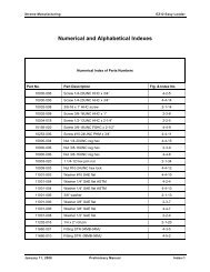
<strong>Xtreme</strong> <strong>Manufacturing</strong>XR2045 ForkliftNumerical List of <strong>Parts</strong> BreakdownsFigure No. Title Page No.2-1 ............. Basic Assembly ......................................................................................................................2-22-2 ............. Final Assembly .......................................................................................................................2-42-3 ............. Chassis Assembly – Engine...................................................................................................2-62-4 ............. Chassis Assembly – Axles ...................................................................................................2-132-5 ............. Chassis Assembly – Covers & Console ...............................................................................2-192-6 ............. Outrigger Mount Assembly...................................................................................................2-223-1 ............. Labels and Load Charts .........................................................................................................3-24-1 ............. Engine Transmission Assembly .............................................................................................4-24-2 ............. Radiator Assembly .................................................................................................................4-64-3 ............. Overflow Tank Assembly........................................................................................................4-94-4 ............. Air Cleaner Assembly ...........................................................................................................4-114-5 ............. Fuel Tank Assembly .............................................................................................................4-135-1 ............. Transmission and Pump Assembly ........................................................................................5-25-2 ............. Front Axle Assembly...............................................................................................................5-45-3 ............. Rear Axle Assembly ...............................................................................................................5-65-4 ............. Front Driveshaft Assembly .....................................................................................................5-85-5 ............. Rear Driveshaft Assembly....................................................................................................5-106-1 ............. Steering Column Assembly ....................................................................................................6-26-2 ............. Brake Charge Valve Assembly...............................................................................................6-46-3 ............. Accumulator Assembly ...........................................................................................................6-76-4 ............. Accumulator Charge Valve Assembly ....................................................................................6-96-5 ............. Brake Pressure Switch Assembly.........................................................................................6-116-6 ............. Wheel Tire Assembly............................................................................................................6-137-1 ............. Hydraulic Tank Assembly .......................................................................................................7-27-2 ............. Hydraulic Tank Lid Assembly .................................................................................................7-47-3 ............. Master Cylinder Assembly 2.75B ...........................................................................................7-67-4 ............. Master Cylinder Assembly 3.50B ...........................................................................................7-87-5 ............. High-Pressure Filter/Steering Valve Assembly ....................................................................7-107-6 ............. Distribution Manifold Assembly ............................................................................................7-127-7 ............. Isolation Manifold Assembly.................................................................................................7-167-8 ............. Boom Manifold Assembly.....................................................................................................7-197-9 ............. Operator Control Valve Assembly ........................................................................................7-217-10 ........... Front Handle Assembly ........................................................................................................7-23August 19, 2011 Preliminary <strong>Manual</strong> v
<strong>Xtreme</strong> <strong>Manufacturing</strong>XR2045 ForkliftNumerical List of <strong>Parts</strong> Breakdowns – Cont.Figure No. Title Page No.7-11 ........... Sway Handle Assembly........................................................................................................7-257-12 ........... Rear Handle Assembly.........................................................................................................7-277-13 ........... Lift Cylinder Assembly ..........................................................................................................7-297-14 ........... Extend Cylinder Assembly....................................................................................................7-317-15 ........... Extend Cylinder Housing Assembly .....................................................................................7-337-16 ........... Extend Cylinder Collar Assembly .........................................................................................7-357-17 ........... Carriage Tilt Cylinder Assembly ...........................................................................................7-377-18 ........... Front Axle Cylinder Assembly ..............................................................................................7-397-19 ........... Rear Axle Cylinder Assembly...............................................................................................7-417-20 ........... Rear Axle Lock Manifold Assembly......................................................................................7-437-21 ........... Boom Hose Kit......................................................................................................................7-457-22 ........... Chassis Hose Kit ..................................................................................................................7-478-1 ............. Electrical Assembly ................................................................................................................8-28-2 ............. Electrical Center Assembly.....................................................................................................8-78-3 ............. Terminal Strip Assembly.........................................................................................................8-98-4 ............. Terminal Strip Assembly.......................................................................................................8-118-5 ............. Terminal Strip Assembly.......................................................................................................8-138-6 ............. Engine Relay Assembly........................................................................................................8-158-7 ............. Battery Disconnect Switch Assembly ...................................................................................8-178-8 ............. Fuse Block Assembly ...........................................................................................................8-198-9 ............. Solenoid Assembly ...............................................................................................................8-219-1 ............. Boom Assembly......................................................................................................................9-29-2 ............. Inner Boom Assembly ............................................................................................................9-49-3 ............. Mid Boom Assembly.............................................................................................................9-119-4 ............. Outer Boom Assembly..........................................................................................................9-159-5 ............. Angle Indicator Assembly.....................................................................................................9-199-6 ............. Slide Block Assembly ...........................................................................................................9-219-7 ............. Outer Boom Roller Assembly ...............................................................................................9-239-8 ............. Roller Assembly....................................................................................................................9-259-9 ............. Tube Clamp Assembly No. 2................................................................................................9-279-10 ........... Hose Clamp Assembly .........................................................................................................9-2910-1 ........... Cab Assembly.......................................................................................................................10-210-2 ........... Enclosed Cab Assembly.......................................................................................................10-810-3 ........... Front Control Console Assembly........................................................................................10-1010-4 ........... Front Control Panel Assembly............................................................................................10-13August 19, 2011 Preliminary <strong>Manual</strong> vi
<strong>Xtreme</strong> <strong>Manufacturing</strong>XR2045 ForkliftNumerical List of <strong>Parts</strong> Breakdowns – Cont.Figure No. Title Page No.10-5 ........... Control Enclosure Subassembly ........................................................................................10-1510-6 ........... Side Control Console Assembly.........................................................................................10-1810-7 ........... Side Console Cover Assembly...........................................................................................10-2110-8 ........... Accelerator Pedal Assembly...............................................................................................10-2310-9 ........... Front Cover Assembly ........................................................................................................10-2510-10 ......... Engine Cover Assembly .....................................................................................................10-2810-11 ......... Radiator Cover Assembly...................................................................................................10-3110-12 ......... Battery Cover Assembly .....................................................................................................10-3310-13 ......... Rear Light Assembly ..........................................................................................................10-3510-14 ......... Radiator Shroud Assembly.................................................................................................10-3710-15 ......... Filler Plate Assembly ..........................................................................................................10-3911-1 ........... Standard Carriage Assembly................................................................................................11-211-2 ........... Adjustable Carriage Assembly .............................................................................................11-4August 19, 2011 Preliminary <strong>Manual</strong> vii
<strong>Xtreme</strong> <strong>Manufacturing</strong>XR2045 ForkliftSection 1General InformationTable 1-1. Abbreviations & AcronymsTermAASTMAWGBHCBKDNDIADPDTFSHCFTGHHCIDLGMMNHANPTODOHMPHMPWHQDREFREGSAESBHCSHCSHSMeaningAmperesAmerican Society for Testing and MaterialsAmerican Wire GaugeButton head capBreakdownDiameterDouble-pole, double-throwFlat socket head capFittingsHex head capInside diameterLongMillimeterNext higher assemblyNational pipe threadOutside diameterOval head machinePan head machinePan washer headQuick-DisconnectReferenceRegularSociety of Automotive EngineersSocket button head capSocket head capSocket head shoulderAugust 19, 2011 Preliminary <strong>Manual</strong> 1-1
<strong>Xtreme</strong> <strong>Manufacturing</strong>XR2045 ForkliftTermSPDTSPSTSTRTHDUNCUNFVMeaningSingle-throw, double-poleSingle-pole, single-throwStraightThreadUnified National CoarseUnified National FineVoltsAugust 19, 2011 Preliminary <strong>Manual</strong> 1-2
<strong>Xtreme</strong> <strong>Manufacturing</strong>XR2045 ForkliftSection 2ChassisAugust 19, 2011 Preliminary <strong>Manual</strong> 2-1
<strong>Xtreme</strong> <strong>Manufacturing</strong> XR2045 ForkliftFigure 2-1. Basic AssemblyAugust 19, 2011 Preliminary <strong>Manual</strong> 2-2
<strong>Xtreme</strong> <strong>Manufacturing</strong>XR2045 ForkliftTable 2-1. Basic AssemblyFigure &Item No.Part No. Description Quantity Use On– 27220-000 Basic assembly 1 –2-1-1 27221-000 Chassis assembly – covers & console 1 –2-1-2 26976-000 Hydraulic tank assembly 1 –2-1-3 27410-000 Cab assembly 1 –2-1-4 27121-000 Isolator retainer plate 4 –2-1-5 11001-008 Washer 1/2 SAE flat 4 –2-1-6 10004-024 Screw 1/2-13UNC HHC x 3 4 –2-1-7 11001-020 Washer 1-1/4 SAE flat 6 –2-1-8 10031-018 Screw 1-1/4-12UNF HHC x 2-1/4 2 –2-1-9 10031-032 Screw 1-1/4-12UNF HHC x 4 2 –2-1-10 10901-020 Hnut 1-1/4-12UNF 2 –Refer to Section 1 for the definition of acronyms and abbreviations used in the Description Column.August 19, 2011 Preliminary <strong>Manual</strong> 2-3
<strong>Xtreme</strong> <strong>Manufacturing</strong> XR2045 ForkliftFigure 2-2. Final AssemblyAugust 19, 2011 Preliminary <strong>Manual</strong> 2-4
<strong>Xtreme</strong> <strong>Manufacturing</strong>XR2045 ForkliftTable 2-2. Final AssemblyFigure &Item No.Part No. Description Quantity Use On– 26753-000 Final assembly – –2-2-1 27220-000 Basic assembly 1 –2-2-2 27372-000 Boom assembly 1 –2-2-3 26914-000 Boom mounting pin 1 –2-2-4 27114-000 Shim washer 2 –2-2-5 27115-000 Shaft collar 2 –2-2-6 26949-000 Rear boom access cover 1 –2-2-7 27062-000 Master cylinder pin assembly 2 –2-2-8 27063-000 Lift cylinder pin assembly 4 –2-2-9 27064-000 Master cylinder pin assembly 2 –2-2-10 27069-000 Lift cylinder assembly 2 –2-2-11 26755-000 Master cylinder assembly 1 –2-2-12 26769-000 Master cylinder assembly 3.50B 1 –2-2-13 11002-008 Extra thick grade 8 SAE washer 8 –2-2-14 10004-010 Screw 1/2-13UNC HHC x 1-1/4 8 –2-2-15 11001-010 Washer 5/8 SAE flat 4 –2-2-16 10006-052 Screw 5/8-11UNC HHC x 6-1/2 2 –2-2-17 10900-010 Nut 5/8-11UNC reg hex 2 –2-2-18 11001-006 Washer 3/8 SAE flat 4 –2-2-19 10002-006 Screw 3/8-16UNC HHC x 3/4 4 –2-2-20 29300-000 Fixed carriage assembly 1 –2-2-21 27356-000 Boom pin support 2 –Refer to Section 1 for the definition of acronyms and abbreviations used in the Description Column.August 19, 2011 Preliminary <strong>Manual</strong> 2-5
<strong>Xtreme</strong> <strong>Manufacturing</strong> XR2045 ForkliftFigure 2-3. Chassis Assembly – Engine (Sheet 1 of 5)August 19, 2011 Preliminary <strong>Manual</strong> 2-6
<strong>Xtreme</strong> <strong>Manufacturing</strong> XR2045 Forklift10109721262011474618131214Figure 2-3. Chassis Assembly – Engine (Sheet 2 of 5)August 19, 2011 Preliminary <strong>Manual</strong> 2-7
<strong>Xtreme</strong> <strong>Manufacturing</strong> XR2045 ForkliftFigure 2-3. Chassis Assembly – Engine (Sheet 3 of 5)August 19, 2011 Preliminary <strong>Manual</strong> 2-8
<strong>Xtreme</strong> <strong>Manufacturing</strong> XR2045 ForkliftFigure 2-3. Chassis Assembly – Engine (Sheet 4 of 5)August 19, 2011 Preliminary <strong>Manual</strong> 2-9
<strong>Xtreme</strong> <strong>Manufacturing</strong> XR2045 Forklift651421312871733203728392621382610109Figure 2-3. Chassis Assembly – Engine (Sheet 5 of 5)August 19, 2011 Preliminary <strong>Manual</strong> 2-10
<strong>Xtreme</strong> <strong>Manufacturing</strong>XR2045 ForkliftTable 2-3. Chassis Assembly – EngineFigure &Index No.Part No. Description Quantity Use On– 27222-000 Chassis assembly – engine 1 –2-3-1 27223-000 Chassis assembly – axles 1 –2-3-2 27055-001 Engine transmission assembly 1 –2-3-3 12353-000 Isolator mount (engine transmission) 2 –2-3-4 12350-000 Isolator mount 2 –2-3-5 27050-001 Radiator assembly 1 –2-3-6 26996-000 Radiator shroud assembly 1 –2-3-7 25214-001 Distribution manifold assembly 1 –2-3-8 25212-004 Isolation manifold assembly 1 –2-3-9 25763-002 HP filter/steering valve assembly 1 –2-3-10 25769-000 Accumulator assembly 2 –2-3-11 13051-000 Back-up alarm 1 –2-3-12 14450-000 Battery 1 –2-3-13 14451-000 Battery J-bolt 2 –2-3-14 14452-000 Battery holddown 1 –2-3-15 14620-000 Drive shaft (rear) 1 –2-3-16 14619-000 Drive shaft (front) 1 –2-3-17 27112-001 Hose/exhaust bracket 1 –2-3-18 26613-000 Battery disconnect switch assembly 1 –2-3-19 27198-000 Hose guard 1 –2-3-20 27434-000 Brake charge valve assembly 1 –2-3-21 26307-000 Boom extend valve assembly 1 –2-3-22 11003-006 Washer 3/8 flat fender 2 –2-3-23 11001-010 Washer 5/8 SAE flat 8 –2-3-24 10006-032 Screw 5/8-11UNC HHC x 4 4 –2-3-25 10900-010 Nut 5/8-11UNC reg hex 4 –August 19, 2011 Preliminary <strong>Manual</strong> 2-11
<strong>Xtreme</strong> <strong>Manufacturing</strong>XR2045 ForkliftTable 2-3. Chassis Assembly – EngineFigure &Index No.Part No. Description Quantity Use On2-3-26 11001-006 Washer 3/8 SAE flat 29 –2-3-27 10002-010 Screw 3/8-16UNC reg hex 6 –2-3-28 10900-006 Nut 3/8-16UNC reg hex 7 –2-3-29 10002-012 Screw 3/8-16UNC HHC x 1-1/2 2 –2-3-30 11001-003 Washer #10 SAE flat 12 –2-3-31 10303-006 Screw #10-24UNC SBHC x 3/4 4 –2-3-32 10908-003 Nut #10-24UNC hex lock 6 –2-3-33 11001-005 Washer 5/16 SAE flat ASTM 12 –2-3-34 10001-006 Screw 5/16-18UNC HHC x 3/4 4 –2-3-35 10253-006 Screw #10-24UNC PHM x 3/4 2 –2-3-36 10002-008 Screw 3/8-16UNC HHC x 1 3 –2-3-37 10001-008 Screw 5/16-18UNC HHC x 1 4 –2-3-38 10022-010 Screw 3/8-24UNF HHC x 1-1/4 4 –2-3-39 10002-036 Screw 3/8-16UNC HHC x 4-1/2 1 –2-3-40 11001-004 Washer 1/4 SAE flat ASTM 8 –2-3-41 10000-006 Screw 1/4-20UNC HHC x 3/4 4 –2-3-42 10900-004 Nut 1/4-20UNC reg hex 4 –2-3-43 11001-008 Washer 1/2 SAE flat 4 –2-3-44 10004-012 Bolt 1/2-13UNC x 1.5 2 –2-3-45 10900-008 Nut 1/2-13UNC reg hex 2 –2-3-46 11001-005 Washer 5/16 SAE flat 6 –2-3-47 10021-024 Screw 5/16-24UNF HHC x 3 2 –2-3-48 10001-024 Screw 5/16-18UNC HHC x 3 2 –2-3-49 10900-005 Nut 5/16-18UNC reg hex 2 –2-3-50 10001-004 Screw 5/16-18UNC HHC x 1/2 4 –Refer to Section 1 for the definition of acronyms and abbreviations used in the Description Column.August 19, 2011 Preliminary <strong>Manual</strong> 2-12
<strong>Xtreme</strong> <strong>Manufacturing</strong> XR2045 ForkliftFigure 2-4. Chassis Assembly – Axles (Sheet 1 of 3)August 19, 2011 Preliminary <strong>Manual</strong> 2-13
<strong>Xtreme</strong> <strong>Manufacturing</strong> XR2045 ForkliftFigure 2-4. Chassis Assembly – Axles (Sheet 2 of 3)August 19, 2011 Preliminary <strong>Manual</strong> 2-14
<strong>Xtreme</strong> <strong>Manufacturing</strong> XR2045 ForkliftFigure 2-4. Chassis Assembly – Axles (Sheet 3 of 3)August 19, 2011 Preliminary <strong>Manual</strong> 2-15
<strong>Xtreme</strong> <strong>Manufacturing</strong>XR2045 ForkliftTable 2-4. Chassis Assembly – AxlesFigure &Item No.Part No. Description Quantity Use On– 27223-000 Chassis assembly – axles – –2-4-1 27270-000 Chassis weldment 1 –2-4-2 27086-000 Front axle assembly 1 –2-4-3 27087-000 Rear axle assembly 1 –2-4-4 14528-000 Wheel/tire assembly 4 –2-4-5 26818-002 Axle cylinder mount weldment 4 –2-4-6 25740-000 Axle cylinder pin weldment 4 –2-4-7 25493-001 Chassis counterweight 1 –2-4-8 27264-000 Sway cylinder assembly (front) 2 –2-4-9 27265-000 Sway cylinder assembly (rear) 2 –2-4-10 26823-001 Outrigger mount assembly 1 –2-4-11 25812-000 Outrigger pin weldment 1 –2-4-12 27036-001 Cylinder mount plate 2 –2-4-13 27039-001 .040 outrigger mount shim 4 –2-4-14 27103-000 Front cover bracket 2 –2-4-15 27104-000 Gas spring bracket (RH) 1 –2-4-16 27104-001 Gas spring bracket (LH) 1 –2-4-17 27108-000 Engine cover track (LH) 1 –2-4-18 27109-000 Engine cover track (RH) 1 –2-4-19 13052-000 Horn 1 –2-4-20 25445-000 Engine relay assembly 1 –2-4-21 27127-000 Pump shield 1 –2-4-22 13728-001 Bearing 3-1/2 x 4 x 6-1/2 2 –2-4-23 12257-000 Grease seal 3-1/2 x 3 4 –2-4-24 11910-000 Fitting grease 1/8 NPT STR 2 –August 19, 2011 Preliminary <strong>Manual</strong> 2-16
<strong>Xtreme</strong> <strong>Manufacturing</strong>XR2045 ForkliftTable 2-4. Chassis Assembly – AxlesFigure &Item No.Part No. Description Quantity Use On2-4-25 13804-014 Spherical bearing 3 ID 2 –2-4-26 13804-009 Spherical bearing 1-3/4 2 –2-4-27 26757-000 Side console assembly 1 –2-4-28 11714-002 Fitting BH tee -6MFS-6MFS-6MFS 5 –2-4-29 11691-002 Nut bulkhead -6MFS 5 –2-4-30 11728-002 Fitting elbow 90 -06MFS-06FFSS 3 –2-4-31 11001-016 Washer 1 dia SAE flat 24 –2-4-32 10029-080 Screw 1-14UNF HHC x 10 8 –2-4-33 10901-016 Nut 1-14UNF reg hex 8 –2-4-34 11002-008 Extra thick grade 8 SAE washer 5 –2-4-35 10004-010 Screw 1/2-13UNC HHC x 1-1/4 5 –2-4-36 11001-014 Washer 7/8 SAE flat 32 –2-4-37 10028-096 Screw 7/8-14UNF HHC x 12 16 –2-4-38 11001-005 Washer 5/16 SAE flat ASTM 17 –2-4-39 10001-005 Screw 5/16-18UNC HHC x 5/8 17 –2-4-40 11001-008 Washer 1/2 SAE flat 9 –2-4-41 10004-014 Screw 1/2-13UNC HHC x 1-3/4 4 –2-4-42 11001-006 Washer 3/8 SAE flat 8 –2-4-43 10002-012 Screw 3/8-16UNC HHC x 1-1/2 4 –2-4-44 10900-006 Nut 3/8-16UNC reg hex 4 –2-4-45 10857-003 Bolt 1-8UNC stud x 6 4 –2-4-46 10949-016 Nut 1-8UNC hex coupling 4 –2-4-47 10900-016 Nut 1-8UNC reg hex 4 –2-4-48 10901-014 Nut 7/8-14UNF reg hex 16 –2-4-49 11001-006 Washer 3/8 SAE flat ASTM 32 –2-4-50 10002-008 Screw 3/8-16UNC HHC x 1 32 –August 19, 2011 Preliminary <strong>Manual</strong> 2-17
<strong>Xtreme</strong> <strong>Manufacturing</strong>XR2045 ForkliftTable 2-4. Chassis Assembly – AxlesFigure &Item No.Part No. Description Quantity Use On2-4-51 10004-008 Screw 1/2-13UNC HHC x 1 4 –Refer to Section 1 for the definition of acronyms and abbreviations used in the Description Column.August 19, 2011 Preliminary <strong>Manual</strong> 2-18
<strong>Xtreme</strong> <strong>Manufacturing</strong> XR2045 ForkliftFigure 2-5. Chassis Assembly – Covers & Console (Sheet 1 of 2)August 19, 2011 Preliminary <strong>Manual</strong> 2-19
<strong>Xtreme</strong> <strong>Manufacturing</strong> XR2045 ForkliftFigure 2-5. Chassis Assembly – Covers & Console (Sheet 2 of 2)August 19, 2011 Preliminary <strong>Manual</strong> 2-20
<strong>Xtreme</strong> <strong>Manufacturing</strong>XR2045 ForkliftTable 2-5. Chassis Assembly – Covers & ConsoleFigure &Item No.Part No. Description Quantity Use On– 27221-000Chassis assembly – covers andconsole– –2-5-1 27222-000 Chassis assembly – engine 1 –2-5-2 13552-001 Draw latch 1 –2-5-3 11252-001 Gas spring 2 –2-5-4 11253-000 Ball end – gas spring 2 –2-5-5 11001-003 Washer #10 SAE flat 2 –2-5-6 10253-004 Screw #10-24UNC PHM x 1/2 2 –2-5-7 11001-004 Washer 1/4 SAE flat ASTM 12 –2-5-8 10900-004 Nut 1/4-20 UNC reg hex 5 –2-5-9 10000-006 Screw 1/4-20UNC HHC x 3/4 7 –2-5-10 27061-002 Engine cover assembly (roller) 1 –2-5-11 26998-000 Battery cover assembly 1 –2-5-12 25758-001 Front cover assembly 1 –2-5-13 25843-002 Radiator cover assembly 1 –2-5-14 25796-000 Hitch pin assembly 1 –2-5-15 13425-000 Mirror (12 x 8) 1 –2-5-16 27262-000 Mirror mounting bracket 1 –2-5-17 26758-000 Side console cover assembly 1 –2-5-18 11001-005 Washer 5/16 SAE flat ASTM 4 –2-5-19 10001-006 Screw 5/16-18UNC HHC x 3/4 4 –Refer to Section 1 for the definition of acronyms and abbreviations used in the Description Column.August 19, 2011 Preliminary <strong>Manual</strong> 2-21
<strong>Xtreme</strong> <strong>Manufacturing</strong>XR2045 ForkliftFigure 2-6. Outrigger Mount Assembly (Sheet 1 of 2)August 19, 2011 Preliminary <strong>Manual</strong> 2-22
<strong>Xtreme</strong> <strong>Manufacturing</strong>XR2045 ForkliftFigure 2-6. Outrigger Mount Assembly (Sheet 2 of 2)August 19, 2011 Preliminary <strong>Manual</strong> 2-23
<strong>Xtreme</strong> <strong>Manufacturing</strong>XR2045 ForkliftTable 2-6. Outrigger Mount AssemblyFigure &Item No.Part No. Description Quantity Use On– 26823-001 Outrigger mount assembly – –2-6-1 26304-001 Outrigger mount assembly 1 –2-6-2 25807-000 Outrigger leg assembly 2 –2-6-3 25817-000 Outrigger cylinder assembly 2 –2-6-4 25808-000 Outrigger foot weldment 2 –2-6-5 25699-000 Pivot sleeve 2 –2-6-6 25672-000 Hitch pin washer 4 –2-6-7 25809-000 Outrigger pivot pin weldment 2 –2-6-8 25811-000 Outrigger cylinder pin weldment 2 –2-6-9 25816-000 Outrigger cylinder pin weldment 2 –2-6-10 25933-000 Outrigger stop cam 2 –2-6-11 26308-000 Outrigger bulkhead assembly 2 –2-6-12 11001-012 Washer 3/4 SAE flat 4 –2-6-13 10007-048 Screw 3/4-10UNC HHC x 6 2 –2-6-14 10900-012 Nut 3/4-10UNC reg hex 2 –2-6-15 11002-008 Extra thick grade 8 SAE washer 6 –2-6-16 10004-012 Screw 1/3-12UNC HHC x 1-1/2 6 –2-6-17 11001-010 Washer 5/8 SAE flat 4 –2-6-18 10900-010 Nut 5/8-11UNC reg hex 2 –2-6-19 11001-006 Washer 3/8 SAE flat 4 –2-6-20 10002-008 Screw 3/8-16UNC HHC x 1 4 –Refer to Section 1 for the definition of acronyms and abbreviations used in the Description Column.August 19, 2011 Preliminary <strong>Manual</strong> 2-24
<strong>Xtreme</strong> <strong>Manufacturing</strong>XR2045 ForkliftSection 3Labels and Load ChartsAugust 19, 2011 Preliminary <strong>Manual</strong> 3-1
<strong>Xtreme</strong> <strong>Manufacturing</strong>XR2045 ForkliftFigure 3-1. Labels and Load Charts (Sheet 1 of 13)August 19, 2011 Preliminary <strong>Manual</strong> 3-2
<strong>Xtreme</strong> <strong>Manufacturing</strong>XR2045 ForkliftFigure 3-1. Labels and Load Charts (Sheet 2 of 13)August 19, 2011 Preliminary <strong>Manual</strong> 3-3
<strong>Xtreme</strong> <strong>Manufacturing</strong>XR2045 ForkliftFigure 3-1. Labels and Load Charts (Sheet 3 of 13)August 19, 2011 Preliminary <strong>Manual</strong> 3-4
18001-001Crab2W4W<strong>Xtreme</strong> <strong>Manufacturing</strong>XR2045 ForkliftParkingBrakeHydraulic OilTemperatureLow BrakePressureRear AxleLockedVoltsFuelOilCoolantOFFON702-636-2969Hourmeter800-497-1704LightsRear AxleCenteredOnOnOffSteeringOffDeclutch1 23 45 6Figure 3-1. Labels and Load Charts (Sheet 4 of 13)August 19, 2011 Preliminary <strong>Manual</strong> 3-5
<strong>Xtreme</strong> <strong>Manufacturing</strong>XR2045 Forklift7 89 1011 12Figure 3-1. Labels and Load Charts (Sheet 5 of 13)August 19, 2011 Preliminary <strong>Manual</strong> 3-6
<strong>Xtreme</strong> <strong>Manufacturing</strong>XR2045 Forklift13 1415 1617 18Figure 3-1. Labels and Load Charts (Sheet 6 of 13)August 19, 2011 Preliminary <strong>Manual</strong> 3-7
<strong>Xtreme</strong> <strong>Manufacturing</strong>XR2045 ForkliftWARNINGFigure 3-1. Labels and Load Charts (Sheet 7 of 13)August 19, 2011 Preliminary <strong>Manual</strong> 3-8
<strong>Xtreme</strong> <strong>Manufacturing</strong>XR2045 Forklift25 2627 2829 30Figure 3-1. Labels and Load Charts (Sheet 8 of 13)August 19, 2011 Preliminary <strong>Manual</strong> 3-9
<strong>Xtreme</strong> <strong>Manufacturing</strong>XR2045 Forklift31 3233 3435 36Figure 3-1. Labels and Load Charts (Sheet 9 of 13)August 19, 2011 Preliminary <strong>Manual</strong> 3-10
<strong>Xtreme</strong> <strong>Manufacturing</strong>XR2045 Forklift37 3839 4041 42Figure 3-1. Labels and Load Charts (Sheet 10 of 13)August 19, 2011 Preliminary <strong>Manual</strong> 3-11
18056-00018057-000<strong>Xtreme</strong> <strong>Manufacturing</strong>XR2045 Forklift43 44AB C DEF4546Max capacity of lifting point is 20,000 lbs.CARRIAGE DAMAGEDAMAGE may result from adjusting forkswhen carriage is loaded.ONLY ADJUST FORKS WHEN CARRIAGEIS UNLOADED.18331-00047 48Figure 3-1. Labels and Load Charts (Sheet 11 of 13)August 19, 2011 Preliminary <strong>Manual</strong> 3-12
<strong>Xtreme</strong> <strong>Manufacturing</strong>XR2045 ForkliftDEATH or SERIOUS INJURY could result fromimproper operation when using tow connection.DO NOT ELEVATE BOOM ABOVE 30 WHENTOWING.DO NOT EXCEED RATED TOW CAPACITY.Max vertical load 500 LBS.Max tow capacity 5000 LBS.18332-00049 5051Max capacity of lifting point is 20,000 lbs.5253Figure 3-1. Labels and Load Charts (Sheet 12 of 13)August 19, 2011 Preliminary <strong>Manual</strong> 3-13
<strong>Xtreme</strong> <strong>Manufacturing</strong>XR2045 Forklift54 5155 51Figure 3-1. Labels and Load Charts (Sheet 13 of 13)August 19, 2011 Preliminary <strong>Manual</strong> 3-14
<strong>Xtreme</strong> <strong>Manufacturing</strong>XR2045 ForkliftTable 3-1. Labels and Load ChartsFigure &Item No.Part No. Description Quantity Use On3-1-1 18008-000 Data plate 1 –3-1-2 18001-001 Dash overlay 1 –3-1-3 18010-001 Caution slip / trip hazard 1 –3-1-4 18011-001 Caution engine damage hazard 1 –3-1-5 18013-001 Diesel only 1 –3-1-6 18014-001 Check engine oil 1 –3-1-7 18015-001 Check / fill coolant 1 –3-1-8 18016-001 Caution burn hazard 1 –3-1-9 18017-001 Danger crushing hazard 2 –3-1-10 18018-001 Danger electrocution hazard 8 –3-1-11 18018-002 Danger electrocution hazard 1 –3-1-12 18019-001 Danger crushing hazard 3 –3-1-13 18020-001 Warning tip over hazard 1 –3-1-14 18021-001 Danger crushing hazard 1 –3-1-15 18022-001 Warning tip over hazard 1 –3-1-16 18023-001 Warning welding modification hazard 1 –3-1-17 18025-001 Warning falling hazard 1 –3-1-18 18026-001 Warning unrestrained operator hazard 1 –3-1-19 18027-001 Danger rotating equipment hazard 1 –3-1-20 18031-001 Warning safe operation checklist 1 –3-1-21 18032-001 Warning improper use hazard 1 –3-1-22 18033-100 Auxiliary handle control 1 –3-1-23 18347-000 Boom handle control 1 –3-1-24 18039-000 Angle indicator 1 –3-1-25 18041-001 Warning pinch point hazard 6 –3-1-26 18042-000 <strong>Xtreme</strong> (small) 3 –August 19, 2011 Preliminary <strong>Manual</strong> 3-15
<strong>Xtreme</strong> <strong>Manufacturing</strong>XR2045 ForkliftTable 3-1. Labels and Load ChartsFigure &Item No.Part No. Description Quantity Use On3-1-27 18066-001 Caution crushing hazard 2 –3-1-28 18067-100 Frame sway handle 1 –3-1-29 18334-001 Handle, auxiliary controls 1 –3-1-30 18069-000 Hydraulic tank fluid level 1 –3-1-31 18082-001 Warning injection hazard 1 –3-1-32 18083-001 Warning explosion hazard 2 –3-1-33 18086-001 Hydraulic fluid use Dexron III 1 –3-1-34 18090-001 Warning tip over hazard 4 –3-1-35 18300-001 Warning falling hazard 2 –3-1-36 18312-000 Warning falling hazard 2 –3-1-37 18315-000 Tie down point 4 –3-1-38 18043-000 <strong>Xtreme</strong> (medium) 2 –3-1-39 18044-000 <strong>Xtreme</strong> “X” 3 –3-1-40 18046-000 Boom swoosh left front 1 –3-1-41 18047-000 Boom swoosh left rear 1 –3-1-42 18048-000 Boom swoosh right front 1 –3-1-43 18049-000 Boom swoosh right rear 1 –3-1-44 18369-000 XR2045 2 –3-1-45 18056-000 Boom lettering A-B-C-D 1 –3-1-46 18057-000 Boom lettering E-F 1 –3-1-47 18311-005 Boom hook, 20K (optional) 1 –3-1-48 18331-000 Caution carriage damage (optional) 1 –3-1-49 18332-000 Warning tow capacity (optional) 1 –3-1-50 18307-001 Warning falling hazard 2 –3-1-51 18306-001 Danger crushing hazard 2 –3-1-52 18306-000 Danger crushing hazard 4 –August 19, 2011 Preliminary <strong>Manual</strong> 3-16
<strong>Xtreme</strong> <strong>Manufacturing</strong>XR2045 ForkliftTable 3-1. Labels and Load ChartsFigure &Item No.Part No. Description Quantity Use On3-1-53 18363-000 Warning, carriage latch 1 –3-1-54 17228-000R01 Load chart, standard carriage, OR up 1 –3-1-55 17229-000R01Load chart, standard carriage, ORdown1 –August 19, 2011 Preliminary <strong>Manual</strong> 3-17
<strong>Xtreme</strong> <strong>Manufacturing</strong>XR2045 ForkliftTHIS PAGE INTENTIONALLY LEFT BLANKAugust 19, 2011 Preliminary <strong>Manual</strong> 3-18
<strong>Xtreme</strong> <strong>Manufacturing</strong>XR2045 ForkliftSection 4EngineAugust 19, 2011 Preliminary <strong>Manual</strong> 4-1
<strong>Xtreme</strong> <strong>Manufacturing</strong> XR2045 ForkliftFigure 4-1. Engine Transmission Assembly (Sheet 1 of 2)August 19, 2011 Preliminary <strong>Manual</strong> 4-2
<strong>Xtreme</strong> <strong>Manufacturing</strong> XR2045 ForkliftFigure 4-1. Engine Transmission Assembly (Sheet 2 of 2)August 19, 2011 Preliminary <strong>Manual</strong> 4-3
<strong>Xtreme</strong> <strong>Manufacturing</strong>XR2045 ForkliftTable 4-1. Engine Transmission AssemblyFigure &Item No.Part No. Description Quantity Use On– 27055-001 Engine transmission assembly – –– 13952-009 Oil filter 1 –– 13952-045 Fuel filter 1 –4-1-1 13956-001 Engine 1 –4-1-2 27056-000 Transmission / pump assembly 1 –4-1-3 27071-000 Air cleaner assembly 1 –4-1-4 25590-000 Air cleaner hose 1 –4-1-5 26999-000 Engine mount weldment 2 –4-1-6 27057-000 Exhaust header weldment 1 –4-1-7 13956-010 Fuel water separator 1 –4-1-8 13970-000 Fan 1 –4-1-9 27046-000 Air intake tube 1 –4-1-10 27047-001 Air intake tube 1 –4-1-11 25955-000 Intake hose 3 1 –4-1-12 12056-000 Reducer hose 2-1/4 to 2 1 –4-1-13 13952-013 Exhaust gasket 1 –4-1-14 14405-000 Exhaust clamp 2-1/2 3 –4-1-15 13952-011 Air intake elbow 1 –4-1-16 26022-001 Air inlet spacer 1 –4-1-17 26024-000 Intake tube bracket 1 –4-1-18 14407-000 Exhaust clamp 2-1/4 1 –4-1-19 14408-000 Exhaust muffler 1 –4-1-20 27158-001 Exhaust pipe 1 –4-1-21 27159-000 Exhaust pipe 1 –4-1-22 25607-000 Muffler mounting band 4 –August 19, 2011 Preliminary <strong>Manual</strong> 4-4
<strong>Xtreme</strong> <strong>Manufacturing</strong>XR2045 ForkliftTable 4-1. Engine Transmission AssemblyFigure &Item No.Part No. Description Quantity Use On4-1-23 27111-002 Muffler hanger left 1 –4-1-24 27111-001 Muffler hanger right 1 –4-1-25 11636-001 Fitting elbow 45 -2MP-2FP 1 –4-1-26 11015-011 Washer M10 flat metric 15 –4-1-27 10405-030 Screw M10-1.5 HHC x 30mm LG 12 –4-1-28 11015-012 Washer M12 flat metric 14 –4-1-29 10406-040 Screw M12-1.75mm HHC x 40mm LG 8 –4-1-30 10406-030 Screw M12-1.75mm HHC x 30mm 6 –4-1-31 10405-035 Screw M10-1.50mm HHC x 35mm 3 –4-1-32 11001-004 Washer 1/4 SAE flat ASTM 22 –4-1-33 10000-008 Screw 1/4-20 UNC HHC x 1 11 –4-1-34 10900-004 Nut 1/4-20 UNC reg hex 11 –4-1-35 11015-014 Washer M16 flat metric 2 –4-1-36 10408-030 Screw M16 x 2.00 HHC x 30mm 2 –4-1-37 11001-005 Washer 5/16 SAE flat ASTM 4 –4-1-38 10001-010 Screw 5/16-18 UNC HHC x 1-1/4 2 –4-1-39 10900-005 Nut 5/16-18 UNC reg hex 2 –4-1-40 11001-006 Washer 3/8 SAE flat 4 –4-1-41 10900-006 Nut 3/8-16 UNC reg hex 2 –4-1-42 10002-010 Screw 3/8-16 UNC reg hex 2 –Refer to Section 1 for the definition of acronyms and abbreviations used in the Description Column.August 19, 2011 Preliminary <strong>Manual</strong> 4-5
<strong>Xtreme</strong> <strong>Manufacturing</strong>XR2045 ForkliftFigure 4-2. Radiator Assembly (Sheet 1 of 2)August 19, 2011 Preliminary <strong>Manual</strong> 4-6
<strong>Xtreme</strong> <strong>Manufacturing</strong>XR2045 ForkliftFigure 4-2. Radiator Assembly (Sheet 2 of 2)August 19, 2011 Preliminary <strong>Manual</strong> 4-7
<strong>Xtreme</strong> <strong>Manufacturing</strong>XR2045 ForkliftTable 4-2. Radiator AssemblyFigure &Item No.Part No. Description Quantity Use On– 27050-000 Radiator assembly – –4-2-1 14558-000 Radiator/cooler assembly 1 –4-2-2 27051-000 Fan shroud weldment 1 –4-2-3 25770-000 Overflow tank assembly 1 –4-2-4 25620-000 Radiator hose (lower) 1 –4-2-5 25621-000 Radiator hose (upper) 1 –4-2-6 25622-000 Air cooler hose (out) 1 –4-2-7 26059-000 Air cooler hose (in) 1 –4-2-8 26415-000 Fan guard weldment 1 –4-2-9 12354-000 Isolator mount 1 –4-2-10 11001-006 Washer 3/8 SAE flat 1 –4-2-11 10900-006 Nut 3/8-16UNC reg hex 1 –4-2-12 11001-005 Washer 5/16 SAE flat ASTM 5 –4-2-13 10001-004 Screw 5/16-18UNC HHC x 1/2 5 –4-2-14 11001-004 Washer 1/4 SAE flat ASTM 4 –4-2-15 10000-005 Screw 1/4-20UNC HHC x 5/8 4 –4-2-16 11701-005 Fitting long STR -10MFS-10MB 2 –Refer to Section 1 for the definition of acronyms and abbreviations used in the Description Column.August 19, 2011 Preliminary <strong>Manual</strong> 4-8
<strong>Xtreme</strong> <strong>Manufacturing</strong>XR2045 Forklift13423Figure 4-3. Overflow Tank AssemblyAugust 19, 2011 Preliminary <strong>Manual</strong> 4-9
<strong>Xtreme</strong> <strong>Manufacturing</strong>XR2045 ForkliftTable 4-3. Overflow Tank AssemblyFigure &Item No.Part No. Description Quantity Use On– 25770-000 Overflow tank assembly – –4-3-1 25597-000 Overflow tank bracket 1 –4-3-2 13503-000 Overflow tank 1 –4-3-3 11001-004 Washer 1/4 SAE flat ASTM 6 –4-3-4 10900-004 Nut 1/4-20UNC reg hex 3 –Refer to Section 1 for the definition of acronyms and abbreviations used in the Description Column.August 19, 2011 Preliminary <strong>Manual</strong> 4-10
<strong>Xtreme</strong> <strong>Manufacturing</strong>XR2045 ForkliftFigure 4-4. Air Cleaner AssemblyAugust 19, 2011 Preliminary <strong>Manual</strong> 4-11
<strong>Xtreme</strong> <strong>Manufacturing</strong>XR2045 ForkliftTable 4-4. Air Cleaner AssemblyFigure &Item No.Part No. Description Quantity Use On– 27071-000 Air cleaner assembly – –– 14362-010 Air filter, primary (not shown) 1 –– 14362-011 Air filter, secondary (not shown) 1 –4-4-1 25539-000 Air cleaner bracket 1 –4-4-2 27183-000 Fuel water separator bracket 1 –4-4-3 14362-000 Air cleaner 1 –4-4-4 14363-000 Air pre-cleaner 1 –4-4-5 14364-000 Adapter sleeve 1 –4-4-6 11370-000 Clamp mount 8” dia 2 –4-4-7 11001-005 Washer 5/16 SAE flat ASTM 8 –4-4-8 10001-008 Screw 5/16-18 UNC HHC x 1 2 –4-4-9 10001-006 Screw 5/16-18 UNC HHC x 3/4 4 –4-4-10 10900-005 Nut 5/16-18 UNC reg hex 4 –Refer to Section 1 for the definition of acronyms and abbreviations used in the Description Column.August 19, 2011 Preliminary <strong>Manual</strong> 4-12
<strong>Xtreme</strong> <strong>Manufacturing</strong>XR2045 ForkliftFigure 4-5. Fuel Tank AssemblyAugust 19, 2011 Preliminary <strong>Manual</strong> 4-13
<strong>Xtreme</strong> <strong>Manufacturing</strong>XR2045 ForkliftTable 4-5. Fuel Tank AssemblyFigure &Item No.Part No. Description Quantity Use On– 26600-001 Fuel tank assembly – –4-5-1 26599-001 Fuel tank weldment 1 –4-5-2 13506-000 Fuel tank cap 3 1 –4-5-3 12852-000 Fuel level sender 1 –4-5-4 11568-003 Plug 3/8 NPT hex SOC pipe 2 –4-5-5 11564-015 Fitting elbow 90 3/4 NPT x 5/8 barb 1 –4-5-6 11564-010 Fitting elbow 90 3/8 NPT x 3/8 barb 1 –Refer to Section 1 for the definition of acronyms and abbreviations used in the Description Column.August 19, 2011 Preliminary <strong>Manual</strong> 4-14
<strong>Xtreme</strong> <strong>Manufacturing</strong>XR2045 ForkliftSection 5Transmission, Axles, and DriveshaftsAugust 19, 2011 Preliminary <strong>Manual</strong> 5-1
<strong>Xtreme</strong> <strong>Manufacturing</strong>XR2045 Forklift137862106115414163141591213Figure 5-1. Transmission and Pump AssemblyAugust 19, 2011 Preliminary <strong>Manual</strong> 5-2
<strong>Xtreme</strong> <strong>Manufacturing</strong>XR2045 ForkliftTable 5-1. Transmission and Pump AssemblyFigure &Item No.Part No. Description Quantity Use On– 27056-000 Transmission and pump assembly – –– 14107-011 Transmission filter 1 –5-1-1 14107-000 Transmission 1 –5-1-2 14003-000 Pump 1 –5-1-3 27042-000 Transmission mount 2 –5-1-4 12353-000 Isolator mount (engine/transmission) 2 –5-1-5 25946-000 Isolator washer 2 –5-1-6 11700-023 Fitting STR 12MFS-12MB 2 –5-1-7 11702-001 Fitting elbow 90 -04MBA-04MFS 1 –5-1-8 11702-011 Fitting elbow 90 -08MBA-08MFS 1 –5-1-9 11698-006 Plug ext hex HD -08MB 1 –5-1-10 11001-010 Washer 5/8 SAE flat 2 –5-1-11 10006-014 Screw 5/8-11 UNC HHC x 1-3/4 2 –5-1-12 11001-012 Washer 3/4 SAE flat 8 –5-1-13 10007-014 Screw 3/4-10 UNC HHC x 1-3/4 8 –5-1-14 11001-006 Washer 3/8 SAE flat 8 –5-1-15 10002-010 Screw 3/8-16 UNC HHC x 1-1/4 4 –5-1-16 10900-006 Nut 3/8-16 UNC reg hex 4 –Refer to Section 1 for the definition of acronyms and abbreviations used in the Description Column.August 19, 2011 Preliminary <strong>Manual</strong> 5-3
<strong>Xtreme</strong> <strong>Manufacturing</strong>XR2045 ForkliftFigure 5-2. Front Axle AssemblyAugust 19, 2011 Preliminary <strong>Manual</strong> 5-4
<strong>Xtreme</strong> <strong>Manufacturing</strong>XR2045 ForkliftTable 5-2. Front Axle AssemblyFigure &Item No.Part No. Description Quantity Use On– 27086-000 Front axle assembly – –5-2-1 14617-000 Front axle 1 –5-2-2 11740-003 Fitting STR 04MFS-14MMORB 4 –5-2-3 11705-005 Fitting elbow 45 -8MBA-6MFS 2 –5-2-4 11729-001 Fitting tee -04MFS-04FFSS-04MFS 2 –Refer to Section 1 for the definition of acronyms and abbreviations used in the Description Column.August 19, 2011 Preliminary <strong>Manual</strong> 5-5
<strong>Xtreme</strong> <strong>Manufacturing</strong>XR2045 ForkliftFigure 5-3. Rear Axle AssemblyAugust 19, 2011 Preliminary <strong>Manual</strong> 5-6
<strong>Xtreme</strong> <strong>Manufacturing</strong>XR2045 ForkliftTable 5-3. Rear Axle AssemblyFigure &Item No.Part No. Description Quantity Use On– 27087-000 Rear axle assembly – –5-3-1 14618-000 Rear axle 1 –5-3-2 11740-003 Fitting STR 04MFS-14MMORB 2 –5-3-3 11705-005 Fitting elbow 45 -8MBA-6MFS 2 –5-3-4 11729-001 Fitting tee -04MFS-04FFSS-04MFS 1 –Refer to Section 1 for the definition of acronyms and abbreviations used in the Description Column.August 19, 2011 Preliminary <strong>Manual</strong> 5-7
<strong>Xtreme</strong> <strong>Manufacturing</strong>XR2045 ForkliftFigure 5-4. Front Driveshaft AssemblyAugust 19, 2011 Preliminary <strong>Manual</strong> 5-8
<strong>Xtreme</strong> <strong>Manufacturing</strong>XR2045 ForkliftTable 5-4. Front Driveshaft AssemblyFigure &Item No.Part No. Description Quantity Use On– 14619-000 Front driveshaft assembly – –5-4-1 14619-010 Cross and bearing kit 2 –5-4-2 14619-011 Slip yoke 1 –5-4-3 14611-012 Screw HHC 8 –Refer to Section 1 for the definition of acronyms and abbreviations used in the Description Column.August 19, 2011 Preliminary <strong>Manual</strong> 5-9
<strong>Xtreme</strong> <strong>Manufacturing</strong>XR2045 ForkliftFigure 5-5. Rear Driveshaft AssemblyAugust 19, 2011 Preliminary <strong>Manual</strong> 5-10
<strong>Xtreme</strong> <strong>Manufacturing</strong>XR2045 ForkliftTable 5-5. Rear Driveshaft AssemblyFigure &Item No.Part No. Description Quantity Use On– 14620-000 Rear driveshaft assembly – –5-5-1 14619-010 Cross and bearing kit 2 –5-5-2 14620-011 Slip yoke 1 –5-5-3 14611-012 Screw HHC 8 –Refer to Section 1 for the definition of acronyms and abbreviations used in the Description Column.August 19, 2011 Preliminary <strong>Manual</strong> 5-11
<strong>Xtreme</strong> <strong>Manufacturing</strong>XR2045 ForkliftTHIS PAGE INTENTIONALLY LEFT BLANKAugust 19, 2011 Preliminary <strong>Manual</strong> 5-12
<strong>Xtreme</strong> <strong>Manufacturing</strong>XR2045 ForkliftSection 6Steering, Brakes, Wheels, and TiresAugust 19, 2011 Preliminary <strong>Manual</strong> 6-1
<strong>Xtreme</strong> <strong>Manufacturing</strong>XR2045 ForkliftFigure 6-1. Steering Column AssemblyAugust 19, 2011 Preliminary <strong>Manual</strong> 6-2
<strong>Xtreme</strong> <strong>Manufacturing</strong>XR2045 ForkliftTable 6-1. Steering Column AssemblyFigure &Item No.Part No. Description Quantity Use On– 26745-000 Steering column assembly – –6-1-1 14006-000 Steering control unit 1 –6-1-2 14650-000 Steering column 1 –6-1-3 10867-003 Stud bolt M10 x 1.50 full THD x 50mm 2 –6-1-4 11705-008 Fitting elbow 45 -8MBA-8MFS 2 –6-1-5 11705-005 Fitting elbow 45 -8MBA-6MFS 2 –6-1-6 11702-001 Fitting elbow 90 -04MBA-04MFS 1 –6-1-7 11015-011 Washer M10 flat metric 2 –6-1-8 10941-011 Nut M10x1.5 hex jam 2 –Refer to Section 1 for the definition of acronyms and abbreviations used in the Description Column.August 19, 2011 Preliminary <strong>Manual</strong> 6-3
<strong>Xtreme</strong> <strong>Manufacturing</strong>XR2045 ForkliftFigure 6-2. Brake Charge Valve Assembly (Sheet 1 of 2)August 19, 2011 Preliminary <strong>Manual</strong> 6-4
<strong>Xtreme</strong> <strong>Manufacturing</strong>XR2045 ForkliftFigure 6-2. Brake Charge Valve Assembly (Sheet 2 of 2)August 19, 2011 Preliminary <strong>Manual</strong> 6-5
<strong>Xtreme</strong> <strong>Manufacturing</strong>XR2045 ForkliftTable 6-2. Brake Charge Valve AssemblyFigure &Item No.Part No. Description Quantity Use On– 27434-002 Brake charge valve assembly – –6-2-1 14273-002 Brake charge valve 1 –6-2-2 11700-001 Fitting STR 04MFS-04MB 1 –6-2-3 11700-009 Fitting STR 06MFS-06MB 3 –6-2-4 11700-010 Fitting STR 06MFS-08MB 2 –6-2-5 11702-010 Fitting elbow 90 -06MBA-08MFS 1 –Refer to Section 1 for the definition of acronyms and abbreviations used in the Description Column.August 19, 2011 Preliminary <strong>Manual</strong> 6-6
<strong>Xtreme</strong> <strong>Manufacturing</strong>XR2045 ForkliftFigure 6-3. Accumulator AssemblyAugust 19, 2011 Preliminary <strong>Manual</strong> 6-7
<strong>Xtreme</strong> <strong>Manufacturing</strong>XR2045 ForkliftTable 6-3. Accumulator AssemblyFigure &Item No.Part No. Description Quantity Use On– 25769-000 Accumulator assembly – –6-3-1 14301-000 Accumulator 1 –6-3-2 11359-000 Accumulator clamp / mount 1 –6-3-3 11700-010 Fitting STR 06MFS-08MB 1 –Refer to Section 1 for the definition of acronyms and abbreviations used in the Description Column.August 19, 2011 Preliminary <strong>Manual</strong> 6-8
<strong>Xtreme</strong> <strong>Manufacturing</strong>XR2045 ForkliftFigure 6-4. Accumulator Charge Valve AssemblyAugust 19, 2011 Preliminary <strong>Manual</strong> 6-9
<strong>Xtreme</strong> <strong>Manufacturing</strong>XR2045 ForkliftTable 6-4. Accumulator Charge Valve AssemblyFigure &Item No.Part No. Description Quantity Use On– 25768-000 Accumulator charge valve assembly – –6-4-1 14205-000 Accumulator charge valve 1 –6-4-2 11700-004 Fitting STR 04MFS-08MB 1 –6-4-3 11705-004 Fitting elbow 45 -06MBA-06MFS 1 –6-4-4 11702-002 Fitting elbow 90 -06MBA-04MFS 1 –6-4-5 11700-013 Fitting STR 08MFS-06MB 1 –6-4-6 11706-006 Fitting tee -08MFS-08MFS-08MBA 2 –Refer to Section 1 for the definition of acronyms and abbreviations used in the Description Column.August 19, 2011 Preliminary <strong>Manual</strong> 6-10
<strong>Xtreme</strong> <strong>Manufacturing</strong>XR2045 ForkliftFigure 6-5. Brake Pressure Switch AssemblyAugust 19, 2011 Preliminary <strong>Manual</strong> 6-11
<strong>Xtreme</strong> <strong>Manufacturing</strong>XR2045 ForkliftTable 6-5. Brake Pressure Switch AssemblyFigure &Item No.Part No. Description Quantity Use On– 25767-000 Brake pressure switch assembly – –6-5-1 13153-000 Brake low pressure switch 1 –6-5-2 11700-001 Fitting STR 04MFS-04MB 1 –Refer to Section 1 for the definition of acronyms and abbreviations used in the Description Column.August 19, 2011 Preliminary <strong>Manual</strong> 6-12
<strong>Xtreme</strong> <strong>Manufacturing</strong>XR2045 ForkliftFigure 6-6. Wheel Tire AssemblyAugust 19, 2011 Preliminary <strong>Manual</strong> 6-13
<strong>Xtreme</strong> <strong>Manufacturing</strong>XR2045 ForkliftTable 6-6. Wheel Tire AssemblyFigure &Item No.Part No. Description Quantity Use On– 14528-000 Wheel tire assembly – –6-6-1 14530-000 Wheel 14 x 25 lock ring 1 –6-6-2 14529-000 Tire 17.5 x 25 (foam filled) 1 –Refer to Section 1 for the definition of acronyms and abbreviations used in the Description Column.August 19, 2011 Preliminary <strong>Manual</strong> 6-14
<strong>Xtreme</strong> <strong>Manufacturing</strong>XR2045 ForkliftSection 7Hydraulic SystemAugust 19, 2011 Preliminary <strong>Manual</strong> 7-1
<strong>Xtreme</strong> <strong>Manufacturing</strong>XR2045 ForkliftFigure 7-1. Hydraulic Tank AssemblyAugust 19, 2011 Preliminary <strong>Manual</strong> 7-2
<strong>Xtreme</strong> <strong>Manufacturing</strong>XR2045 ForkliftTable 7-1. Hydraulic Tank AssemblyFigure &Item No.Part No. Description Quantity Use On– 26976-000 Hydraulic tank assembly – –7-1-1 26977-000 Hydraulic tank 1 –7-1-2 13160-000 Temperature switch 1 –7-1-3 11700-014 Fitting STR 08MFS-08MB 1 –7-1-4 11705-020 Fitting elbow 45 -24MBA-24MFS 1 –7-1-5 11698-008 Plug EXT hex HD -12MB 1 –7-1-6 11698-006 Plug EXT hex HD -08MB 1 –7-1-7 12355-000 Shock mount 1-3/8 DIA 4 –Refer to Section 1 for the definition of acronyms and abbreviations used in the Description Column.August 19, 2011 Preliminary <strong>Manual</strong> 7-3
<strong>Xtreme</strong> <strong>Manufacturing</strong>XR2045 ForkliftFigure 7-2. Hydraulic Tank Lid AssemblyAugust 19, 2011 Preliminary <strong>Manual</strong> 7-4
<strong>Xtreme</strong> <strong>Manufacturing</strong>XR2045 ForkliftTable 7-2. Hydraulic Tank Lid AssemblyFigure &Item No.Part No. Description Quantity Use On– 26715-002 Hydraulic tank lid assembly – –7-2-1 26714-001 Filler breather plate weldment 1 –7-2-2 12250-001 Seal O-ring 6.484 ID 1 –7-2-3 11698-011 Plug external hex HD-20MB 1 –7-2-4 14368-000 Breather 1 –Refer to Section 1 for the definition of acronyms and abbreviations used in the Description Column.August 19, 2011 Preliminary <strong>Manual</strong> 7-5
<strong>Xtreme</strong> <strong>Manufacturing</strong>XR2045 ForkliftFigure 7-3. Master Cylinder Assembly 2.75BAugust 19, 2011 Preliminary <strong>Manual</strong> 7-6
<strong>Xtreme</strong> <strong>Manufacturing</strong>XR2045 ForkliftTable 7-3. Master Cylinder Assembly 2.75BFigure &Item No.Part No. Description Quantity Use On– 26755-000 Master cylinder assembly 2.75B – –– 27349-010 Seal kit (not shown) 1 –7-3-1 27349-000 Master cylinder 1 –7-3-2 11702-011 Fitting elbow 90 -08MBA-08MFS 1 –7-3-3 11700-014 Fitting STR -08MB-08MFS 1 –Refer to Section 1 for the definition of acronyms and abbreviations used in the Description Column.August 19, 2011 Preliminary <strong>Manual</strong> 7-7
<strong>Xtreme</strong> <strong>Manufacturing</strong>XR2045 ForkliftFigure 7-4. Master Cylinder Assembly 3.5BAugust 19, 2011 Preliminary <strong>Manual</strong> 7-8
<strong>Xtreme</strong> <strong>Manufacturing</strong>XR2045 ForkliftTable 7-4. Master Cylinder Assembly 3.5BFigure &Item No.Part No. Description Quantity Use On– 26769-000 Master cylinder assembly 3.5B – –– 27350-010 Seal kit (not shown) 1 –7-4-1 27350-000 Master cylinder 1 –7-4-2 11702-011 Fitting elbow 90 -08MBA-08MFS 1 –7-4-3 11700-014 Fitting STR -08MB-08MFS 1 –Refer to Section 1 for the definition of acronyms and abbreviations used in the Description Column.August 19, 2011 Preliminary <strong>Manual</strong> 7-9
<strong>Xtreme</strong> <strong>Manufacturing</strong>XR2045 Forklift356174524Figure 7-5. High-Pressure Filter/Steering Valve AssemblyAugust 19, 2011 Preliminary <strong>Manual</strong> 7-10
<strong>Xtreme</strong> <strong>Manufacturing</strong>XR2045 ForkliftTable 7-5. High-Pressure Filter/Steering Valve AssemblyFigure &Item No.Part No. Description Quantity Use On– 25763-002 High-pressure filter/steering valveassembly– –7-5-1 14359-000 High pressure filter 1 –7-5-2 14242-000 Steering priority valve 1 –7-5-3 11651-009 Fitting STR -20MBA-20MB 1 –7-5-4 11702-001 Fitting elbow 90 -04MBA-04MFS 2 –7-5-5 11700-028 Fitting STR 16MFS-20MB 2 –7-5-6 11707-007 Fitting tee -8MFS-12MBA-8MFS 1 –7-5-7 14360-000 Filter element 1 –Refer to Section 1 for the definition of acronyms and abbreviations used in the Description Column.August 19, 2011 Preliminary <strong>Manual</strong> 7-11
<strong>Xtreme</strong> <strong>Manufacturing</strong>XR2045 ForkliftFigure 7-6. Distribution Manifold Assembly (Sheet 1 of 3)August 19, 2011 Preliminary <strong>Manual</strong> 7-12
<strong>Xtreme</strong> <strong>Manufacturing</strong>XR2045 ForkliftFigure 7-6. Distribution Manifold Assembly (Sheet 2 of 3)August 19, 2011 Preliminary <strong>Manual</strong> 7-13
<strong>Xtreme</strong> <strong>Manufacturing</strong>XR2045 ForkliftFigure 7-6. Distribution Manifold Assembly (Sheet 3 of 3)August 19, 2011 Preliminary <strong>Manual</strong> 7-14
<strong>Xtreme</strong> <strong>Manufacturing</strong>XR2045 ForkliftTable 7-6. Distribution Manifold AssemblyFigure &Item No.Part No. Description Quantity Use On– 25217-000 Distribution manifold assembly – –7-6-1 14278-000 Distribution manifold 1 –7-6-2 11700-001 Fitting STR 04MFS-04MB 5 –7-6-3 11700-009 Fitting STR 06MFS-06MB 7 –7-6-4 11700-014 Fitting STR 08MFS-08MB 5 –7-6-5 11702-027 Fitting STR 16MFS-16MB 3 –7-6-6 11702-001 Fitting elbow 90 -04MBA-04MFS 2 –7-6-7 11702-023 Fitting elbow 90 -16MBA-16MFS 1 –7-6-8 14278-014 Directional valve 1 –7-6-9 14255-015 Cartridge 1 –7-6-10 14255-019 Check valve 1 –7-6-11 14255-018 Cartridge 1 –7-6-12 14255-016 Cartridge 1 –7-6-13 14255-010 Pressure reduction valve 1 –7-6-14 14255-017 Pressure reduction valve 1 –7-6-15 14255-012 Cartridge 2 –7-6-16 14361-000 Filter 1 –7-6-17 14255-013 Cartridge 1 –7-6-18 14255-023 Orifice 1.00 mm dia 3 –7-6-19 14255-022 Orifice 0.75 mm dia 1 –Refer to Section 1 for the definition of acronyms and abbreviations used in the Description Column.August 19, 2011 Preliminary <strong>Manual</strong> 7-15
<strong>Xtreme</strong> <strong>Manufacturing</strong>XR2045 ForkliftFigure 7-7. Isolation Manifold Assembly (Sheet 1 of 2)August 19, 2011 Preliminary <strong>Manual</strong> 7-16
<strong>Xtreme</strong> <strong>Manufacturing</strong>XR2045 ForkliftFigure 7-7. Isolation Manifold Assembly (Sheet 2 of 2)August 19, 2011 Preliminary <strong>Manual</strong> 7-17
<strong>Xtreme</strong> <strong>Manufacturing</strong>XR2045 ForkliftTable 7-7. Isolation Manifold AssemblyFigure &Index No.Part No. Description Quantity Use On– 25212-004 Isolation manifold assembly – –7-7-1 14275-000 Isolation manifold 1 –7-7-2 11702-006 Fitting elbow 90 -06MBA-06MFS 1 –7-7-3 11700-014 Fitting STR -08MB-08MFS 7 –7-7-4 11700-009 Fitting STR -06MB-06MFS 2 –7-7-5 11700-019 Fitting STR -10MB-10MFS 2 –7-7-6 11700-023 Fitting STR -12MB-12MFS 1 –7-7-7 11702-011 Fitting elbow 90 -08MBA-08MFS 2 –7-7-8 14275-011 Counterbalance valve cartridge 1 –7-7-9 14275-012 Counterbalance valve cartridge 1 –7-7-10 14275-013 Check valve cartridge 1 –7-7-11 14275-014 Shuttle valve cartridge 1 –7-7-12 14275-015 Pilot operated 2-way 1 –7-7-13 14275-016 Pressure reducing valve 1 –Refer to Section 1 for the definition of acronyms and abbreviations used in the Description Column.August 19, 2011 Preliminary <strong>Manual</strong> 7-18
<strong>Xtreme</strong> <strong>Manufacturing</strong>XR2045 ForkliftFigure 7-8. Boom Manifold AssemblyAugust 19, 2011 Preliminary <strong>Manual</strong> 7-19
<strong>Xtreme</strong> <strong>Manufacturing</strong>XR2045 ForkliftTable 7-8. Boom Manifold AssemblyFigure &Index No.Part No. Description Quantity Use On– 29377-000 Boom manifold assembly – –7-8-1 29378-000 Boom tube manifold 1 –7-8-2 11702-014 Fitting elbow 90 -08MBA-10MFS 4 –7-8-3 11700-014 Fitting STR -08MB-08MFS 4 –Refer to Section 1 for the definition of acronyms and abbreviations used in the Description Column.August 19, 2011 Preliminary <strong>Manual</strong> 7-20
<strong>Xtreme</strong> <strong>Manufacturing</strong>XR2045 ForkliftFigure 7-9. Operator Control Valve AssemblyAugust 19, 2011 Preliminary <strong>Manual</strong> 7-21
<strong>Xtreme</strong> <strong>Manufacturing</strong>XR2045 ForkliftTable 7-9. Operator Control Valve AssemblyFigure &Item No.Part No. Description Quantity Use On– 26653-001 Operator control valve assembly – –7-9-1 14236-000 Operator control valve 1 –7-9-2 25772-004 Front handle assembly 1 –7-9-3 25773-001 Rear handle assembly 1 –7-9-4 50508-000 Sway handle assembly 1 –7-9-5 11700-001 Fitting STR 04MFS-04MB 1 –7-9-6 11700-011 Fitting STR 06MFS-10MB 4 –7-9-7 11700-015 Fitting STR 08MFS-10MB 4 –7-9-8 11700-019 Fitting STR 10MFS-10MB 1 –7-9-9 11702-019 Fitting elbow 90 -12MBA-12MFS 1 –7-9-10 11702-022 Fitting elbow 90 -12MBA-16MFS 1 –7-9-11 11705-013 Fitting elbow 45 -10MBA-12MFS 1 –Refer to Section 1 for the definition of acronyms and abbreviations used in the Description Column.August 19, 2011 Preliminary <strong>Manual</strong> 7-22
<strong>Xtreme</strong> <strong>Manufacturing</strong>XR2045 Forklift615423Figure 7-10. Front Handle AssemblyAugust 19, 2011 Preliminary <strong>Manual</strong> 7-23
<strong>Xtreme</strong> <strong>Manufacturing</strong>XR2045 ForkliftTable 7-10. Front Handle AssemblyFigure &Item No.Part No. Description Quantity Use On– 25772-004 Front handle assembly – –– 12809-012 Wire harness (not shown) 1 –7-10-1 12809-000 Front handle grip 1 –7-10-2 25611-002 Control handle rod 1 –7-10-3 10902-006 Nut 3/8-16 UNC hex jam 1 –7-10-4 11201-010 Spacer 1 –7-10-5 11201-012 Roll pin (3/16 x 1-1/2) 1 –7-10-6 12809-011 Control board 1 –Refer to Section 1 for the definition of acronyms and abbreviations used in the Description Column.August 19, 2011 Preliminary <strong>Manual</strong> 7-24
<strong>Xtreme</strong> <strong>Manufacturing</strong>XR2045 ForkliftFigure 7-11. Sway Handle AssemblyAugust 19, 2011 Preliminary <strong>Manual</strong> 7-25
<strong>Xtreme</strong> <strong>Manufacturing</strong>XR2045 ForkliftTable 7-11. Sway Handle AssemblyFigure &Item No.Part No. Description Quantity Use On– 50508-000 Sway handle assembly – –7-11-1 50507-000 Sway valve handle 1 –7-11-2 50504-000 Sway handle weldment 1 –7-11-3 14204-001 Handle nut 1 –7-11-4 50503-000 Sway handle grip 2 –7-11-5 10353-002 Screw #10-24 UNC HS set x 1/4 2 –Refer to Section 1 for the definition of acronyms and abbreviations used in the Description Column.August 19, 2011 Preliminary <strong>Manual</strong> 7-26
<strong>Xtreme</strong> <strong>Manufacturing</strong>XR2045 ForkliftFigure 7-12. Rear Handle AssemblyAugust 19, 2011 Preliminary <strong>Manual</strong> 7-27
<strong>Xtreme</strong> <strong>Manufacturing</strong>XR2045 ForkliftTable 7-12. Rear Handle AssemblyFigure &Item No.Part No. Description Quantity Use On– 25773-001 Rear handle assembly – –7-12-1 25613-000 Rear valve handle 1 –7-12-2 14204-001 Handle nut 1 –7-12-3 14204-002 Handle knob 1 –Refer to Section 1 for the definition of acronyms and abbreviations used in the Description Column.August 19, 2011 Preliminary <strong>Manual</strong> 7-28
<strong>Xtreme</strong> <strong>Manufacturing</strong>XR2045 Forklift321Figure 7-13. Lift Cylinder AssemblyAugust 19, 2011 Preliminary <strong>Manual</strong> 7-29
<strong>Xtreme</strong> <strong>Manufacturing</strong>XR2045 ForkliftTable 7-13. Lift Cylinder AssemblyFigure &Item No.Part No. Description Quantity Use On– 27069-002 Lift cylinder assembly – –– 26822-012 Seal kit (not shown) 1 –7-13-1 26822-002 Lift cylinder 1 –7-13-2 11700-010 Fitting STR 06MFS-08MB 1 –7-13-6 11702-015 Fitting elbow 90 -10MBA-10MFS 1 –Refer to Section 1 for the definition of acronyms and abbreviations used in the Description Column.August 19, 2011 Preliminary <strong>Manual</strong> 7-30
<strong>Xtreme</strong> <strong>Manufacturing</strong>XR2045 ForkliftFigure 7-14. Extend Cylinder AssemblyAugust 19, 2011 Preliminary <strong>Manual</strong> 7-31
<strong>Xtreme</strong> <strong>Manufacturing</strong>XR2045 ForkliftTable 7-14. Extend Cylinder AssemblyFigure &Item No.Part No. Description Quantity Use On– 26778-000 Extend cylinder assembly – –7-14-1 26591-000 Cylinder collar assembly 1 –7-14-2 11702-015 Fitting elbow 90 -10MBA-10MFS 2 –7-14-3 27352-000 Extend cylinder 1 –Refer to Section 1 for the definition of acronyms and abbreviations used in the Description Column.August 19, 2011 Preliminary <strong>Manual</strong> 7-32
<strong>Xtreme</strong> <strong>Manufacturing</strong>XR2045 Forklift1REF65210489781REF31Figure 7-15. Extend Cylinder Housing AssemblyAugust 19, 2011 Preliminary <strong>Manual</strong> 7-33
<strong>Xtreme</strong> <strong>Manufacturing</strong>XR2045 ForkliftTable 7-15. Extend Cylinder Housing AssemblyFigure &Item No.Part No. Description Quantity Use On– 26772-000 Extend cylinder housing assembly – –7-15-1 27336-000 Extend cylinder housing weldment 1 –7-15-2 10853-003 Stud bolt 1/2-13UNC x 3 2 –7-15-3 29382-000 Extend cylinder housing guide 2 –7-15-4 29381-000 Slide pad, 3.00 x 5.25 x .25 1 –7-15-5 11001-004 Washer 1/4 SAE flat ASTM 2 –7-15-6 10906-005 Nut 5/16UNC hex elastic lock 2 –7-15-7 10001-028 Screw 5/16-18UNC HHC x 3-1/2 4 –7-15-8 11001-005 Washer 5/16 SAE flat 8 –7-15-9 10908-005 Nut 5/16-18UNC hex lock reg 4 –7-15-10 10101-007 Screw 1/4-20UNC-2B SBHC x 7/8 2 –Refer to Section 1 for the definition of acronyms and abbreviations used in the Description Column.August 19, 2011 Preliminary <strong>Manual</strong> 7-34
<strong>Xtreme</strong> <strong>Manufacturing</strong>XR2045 Forklift44221123 23Figure 7-16. Extend Cylinder Collar AssemblyAugust 19, 2011 Preliminary <strong>Manual</strong> 7-35
<strong>Xtreme</strong> <strong>Manufacturing</strong>XR2045 ForkliftTable 7-16. Extend Cylinder Collar AssemblyFigure &Item No.Part No. Description Quantity Use On– 26591-000 Extend cylinder collar assembly – –7-16-1 26164-000 Cylinder mount/collar 2 –7-16-2 11001-004 Washer 1/4 SAE flat ASTM 4 –7-16-3 10908-004 Nut 1/4-20UNC hex lock reg 2 –7-16-4 10000-032 Screw 1/4-20UNC HHC x 4 2 –Refer to Section 1 for the definition of acronyms and abbreviations used in the Description Column.August 19, 2011 Preliminary <strong>Manual</strong> 7-36
<strong>Xtreme</strong> <strong>Manufacturing</strong>XR2045 ForkliftFigure 7-17. Carriage Tilt Cylinder AssemblyAugust 19, 2011 Preliminary <strong>Manual</strong> 7-37
<strong>Xtreme</strong> <strong>Manufacturing</strong>XR2045 ForkliftTable 7-17. Carriage Tilt Cylinder AssemblyFigure &Item No.Part No. Description Quantity Use On– 26759-000 Carriage tilt cylinder assembly – –7-17-1 27351-000 Tilt cylinder 1 –7-17-2 11702-001 Fitting elbow 90 -04MBA-04MFS 2 –Refer to Section 1 for the definition of acronyms and abbreviations used in the Description Column.August 19, 2011 Preliminary <strong>Manual</strong> 7-38
<strong>Xtreme</strong> <strong>Manufacturing</strong>XR2045 Forklift3241Figure 7-18. Front Axle Cylinder AssemblyAugust 19, 2011 Preliminary <strong>Manual</strong> 7-39
<strong>Xtreme</strong> <strong>Manufacturing</strong>XR2045 ForkliftTable 7-18. Front Axle Cylinder AssemblyFigure &Item No.Part No. Description Quantity Use On– 27264-000 Front axle cylinder assembly – –– 27263-010 Axle cylinder seal kit 1 –7-18-1 27263-000 Axle sway cylinder 1 –7-18-2 29236-001 Pin (2.50 x 2.68 grip) 2 –7-18-3 11702-006 Fitting elbow 90 -06MBA-06MFS 1 –7-18-4 11700-009 Fitting STR 06MFS-06MB 1 –Refer to Section 1 for the definition of acronyms and abbreviations used in the Description Column.August 19, 2011 Preliminary <strong>Manual</strong> 7-40
<strong>Xtreme</strong> <strong>Manufacturing</strong>XR2045 ForkliftFigure 7-19. Rear Axle Cylinder AssemblyAugust 19, 2011 Preliminary <strong>Manual</strong> 7-41
<strong>Xtreme</strong> <strong>Manufacturing</strong>XR2045 ForkliftTable 7-19. Rear Axle Cylinder AssemblyFigure &Item No.Part No. Description Quantity Use On– 27265-000 Rear axle cylinder assembly – –– 27263-010 Seal kit (not shown) 1 –7-19-1 27263-000 Axle sway cylinder 1 –7-19-2 14257-000 Rear axle lock manifold 1 –7-19-3 29241-000 Rear axle valve cover 1 –7-19-4 29236-001 Pin (2.50 x 2.68 grip) 2 –7-19-5 11700-009 Fitting STR 06MFS-06MB 2 –7-19-6 11910-000 Fitting grease 1/8 NPT STR 1 –7-19-7 11702-006 Fitting elbow 90 -06MBA-06MFS 1 –7-19-8 11001-006 Washer 3/8 SAE flat ASTM 2 –7-19-9 11001-005 Washer 5/16 SAE flat 4 –7-19-10 10001-024 Screw 5/16-18UNC HHC x 3 4 –7-19-11 10002-024 Screw 3/8-16UNC HHC x 3 2 –Refer to Section 1 for the definition of acronyms and abbreviations used in the Description Column.August 19, 2011 Preliminary <strong>Manual</strong> 7-42
<strong>Xtreme</strong> <strong>Manufacturing</strong>XR2045 ForkliftFigure 7-20. Rear Axle Lock Manifold AssemblyAugust 19, 2011 Preliminary <strong>Manual</strong> 7-43
<strong>Xtreme</strong> <strong>Manufacturing</strong>XR2045 ForkliftTable 7-20. Rear Axle Lock Manifold AssemblyFigure &Item No.Part No. Description Quantity Use On– 25213-000 Rear axle lock manifold assembly – –7-20-1 14257-000 Rear axle lock manifold 1 –7-20-2 11700-009 Fitting STR -06MB-06MFS 1 –Refer to Section 1 for the definition of acronyms and abbreviations used in the Description Column.August 19, 2011 Preliminary <strong>Manual</strong> 7-44
<strong>Xtreme</strong> <strong>Manufacturing</strong>XR2045 ForkliftTO BE SUPPLIEDFigure 7-21. Boom Hose KitAugust 19, 2011 Preliminary <strong>Manual</strong> 7-45
<strong>Xtreme</strong> <strong>Manufacturing</strong>XR2045 ForkliftTable 7-21. Boom Hose KitFigure &Item No.Part No. Description Quantity Use On– 29432-000 Boom hose kit – –7-21-1 12010-384 Auxiliary 2 –7-21-2 12010-348 Tilt 2 –7-21-3 12012-022 Extend 2 –7-21-4 12014-225 Extend, Hawe to boom 1 –Refer to Section 1 for the definition of acronyms and abbreviations used in the Description Column.August 19, 2011 Preliminary <strong>Manual</strong> 7-46
<strong>Xtreme</strong> <strong>Manufacturing</strong>XR2045 ForkliftTO BE SUPPLIEDFigure 7-22. Chassis Hose KitAugust 19, 2011 Preliminary <strong>Manual</strong> 7-47
<strong>Xtreme</strong> <strong>Manufacturing</strong>XR2045 ForkliftTable 7-22. Chassis Hose KitFigure &Item No.Part No. Description Quantity Use On– 27224-000 Chassis hose kit – –7-22-1 12000-013 Charge valve to P.S. 1 –7-22-2 12000-060 Control valve L.S.-LS5 1 –7-22-3 12000-065 Pump L.S.-LS1 1 –7-22-4 12002-015 Brake charge valve L.S.-LS4 1 –7-22-5 12002-017 Brake crossover 1 –7-22-6 12002-042 Steer L.S.-LS3 1 –7-22-7 12002-048 Park brake release 1 –7-22-8 12002-080 Brake front (valve top port) 1 –7-22-9 12002-146 Brake rear(valve bottom port) 1 –7-22-10 12003-017 Priority valve T-T2 1 –7-22-11 12003-017 Brake crossover 1 –7-22-12 12003-020 Priority valve L.S.-LS2 1 –7-22-13 12003-020 Brake crossover 1 –7-22-14 12004-030 Charge valve T- T4 1 –7-22-15 12004-035 FLL to F-sway tee 1 –7-22-16 12006-026 Accumulator supply B 1 –7-22-17 12006-026 Accumulator supply A 1 –7-22-18 12006-035 F-sway tee to cyl 4 –7-22-19 12006-038 R-sway tee to cyl 4 –7-22-20 12006-045 Brake valve ret.(pedal) 1 –7-22-21 12006-045 Brake valve supply 1 –7-22-22 12006-045 Brake valve supply 1 –7-22-23 12006-060 Frame level Hawe A- FLA 1 –7-22-24 12006-081 Frame level Hawe B-front cyl. R 1 –August 19, 2011 Preliminary <strong>Manual</strong> 7-48
<strong>Xtreme</strong> <strong>Manufacturing</strong>XR2045 ForkliftTable 7-22. Chassis Hose KitFigure &Item No.Part No. Description Quantity Use On7-22-25 12006-124 Rear axle lock-ALR 1 –7-22-26 12006-124 Rear axle lock-ALL 1 –7-22-27 12006-124 Rear axle lock-ALS 1 –7-22-28 12007-038 R-sway tee (ALS) to CYL 2 –7-22-29 12008-075 Fork tilt FTD- Lft. cyl 1 –7-22-30 12008-075 Fork tilt FTU- Rt. cyl 1 –7-22-31 12010-042 Front str. (FSB-R cyl.) 1 –7-22-32 12010-045 Steer unit R-SVR 1 –7-22-33 12010-055 Charge valve. P - priority BR 1 –7-22-34 12010-070 Front str. (st. valve-L cyl.) 1 –7-22-35 12010-075 Steer P – divider 1 –7-22-36 12010-108 Rear steering (RSB) 1 –7-22-37 12010-144 Boom lower(A to BA) 1 –7-22-38 12010-146 Fork tilt A to FTA 1 –7-22-39 12010-146 Fork tilt B to FTB 1 –7-22-40 12010-224 Tele retract.- Hawe A 1 –7-22-41 12011-054 Steer return-T3 1 –7-22-42 12011-145 Steering, R-LHS to RSA 1 –7-22-43 12018-150 Boom lift B-BB 1 –7-22-44 12019-070 Control valve P-P2 1 –7-22-45 12022-014 Valve block P1-divider EF 1 –7-22-46 12027-036 Suction 1 –7-22-47 12036-065 Master/slave Lft base end 1 –7-22-48 12036-065 Master/slave Rt.base end 1 –7-22-49 12037-065 BD1-Rt cyl port R 1 –7-22-50 12037-065 BD2-L cyl port E 1 –August 19, 2011 Preliminary <strong>Manual</strong> 7-49
<strong>Xtreme</strong> <strong>Manufacturing</strong>XR2045 ForkliftTable 7-22. Chassis Hose KitFigure &Item No.Part No. Description Quantity Use On7-22-51 12038-065 BU1-R cyl port E. 1 –7-22-52 12038-065 BU2-Left cyl port E 1 –7-22-53 12041-228 Aux A and B 1 –7-22-54 12041-228 Aux A and B 1 –7-22-55 12046-035 Return Hydac-tank 1 –7-22-56 12048-061 Control valve return 1 –7-22-57 12049-048 Pump case drain 1 –7-22-58 16002-064 Rt. Master rod end hose 1 –7-22-59 16002-064 Lft Master rod end hose 1 –7-22-60 16004-111 Master/slave tank line 1 –7-22-61 16053-065 Pump -H.P filter 1 –7-22-62 16091-060 Bottom cooler to bottom trans 1 –7-22-63 16091-066 Top cooler to top trans 1 –Refer to Section 1 for the definition of acronyms and abbreviations used in the Description Column.August 19, 2011 Preliminary <strong>Manual</strong> 7-50
<strong>Xtreme</strong> <strong>Manufacturing</strong>XR2045 ForkliftSection 8Electrical SystemAugust 19, 2011 Preliminary <strong>Manual</strong> 8-1
<strong>Xtreme</strong> <strong>Manufacturing</strong>XR2045 ForkliftFigure 8-1. Electrical Assembly (Sheet 1 of 3)August 19, 2011 Preliminary <strong>Manual</strong> 8-2
<strong>Xtreme</strong> <strong>Manufacturing</strong>XR2045 Forklift151617169 6 187 17 8161111818142 28 27 26 1013121114120194232222212222Figure 8-1. Electrical Assembly (Sheet 2 of 3)August 19, 2011 Preliminary <strong>Manual</strong> 8-3
<strong>Xtreme</strong> <strong>Manufacturing</strong>XR2045 ForkliftFigure 8-1. Electrical Assembly (Sheet 3 of 3)August 19, 2011 Preliminary <strong>Manual</strong> 8-4
<strong>Xtreme</strong> <strong>Manufacturing</strong>XR2045 ForkliftTable 8-1. Electrical AssemblyFigure &Item No.Part No. Description Quantity Use On– 25015-000 Electrical assembly – –8-1-1 25637-000 Front control panel 1 –8-1-2 25643-001 Console access panel 1 –8-1-3 25842-001 Electrical center assembly 1 –8-1-4 26690-000 Fuse block assembly 1 –8-1-5 26683-001 Solenoid assembly 1 –8-1-6 12750-000 Fuel level gauge 1 –8-1-7 12751-000 Oil pressure gauge 1 –8-1-8 12752-000 Coolant temp gauge 1 –8-1-9 12753-000 Volt gauge 1 –8-1-10 12754-000 Hour meter 1 –8-1-11 13158-001 Toggle switch DPDT maintained 2 –8-1-12 13158-002 Toggle switch SPDT 3 pos.maintained1 –8-1-13 13158-004 Toggle switch SPST maintained 1 –8-1-14 13158-003 Toggle switch SPDT 3 pos.momentary2 –8-1-15 13159-000 Switch guard 1 –8-1-16 13402-001 Indicator light red 3 –8-1-17 13402-002 Indicator light amber 2 –8-1-18 13402-004 Indicator light green 3 –8-1-19 25878-001 Terminal strip assembly #6x16 1 –8-1-20 25878-002 Terminal strip assembly #6x18 1 –8-1-21 25877-001 Terminal strip assembly #8x12 1 –8-1-22 13261-000 Jumper #8 cinch 95B 4 –8-1-23 11001-004 Washer 1/4 SAE flat ASTM 2 –August 19, 2011 Preliminary <strong>Manual</strong> 8-5
<strong>Xtreme</strong> <strong>Manufacturing</strong>XR2045 ForkliftTable 8-1. Electrical AssemblyFigure &Item No.Part No. Description Quantity Use On8-1-24 10254-006 Screw 1/4-20UNC PHM x 3/4 2 –8-1-25 13908-002 Nut #8-32UNC hex lock 12 –8-1-26 10252-004 Screw #8-32UNC PH machine x 1/2 14 –8-1-27 11001-001 Washer #6 SAE flat 2 –8-1-28 10908-001 Nut #6-32UNC hex lock 2 –Refer to Section 1 for the definition of acronyms and abbreviations used in the Description Column.August 19, 2011 Preliminary <strong>Manual</strong> 8-6
<strong>Xtreme</strong> <strong>Manufacturing</strong>XR2045 ForkliftFigure 8-2. Electrical Center AssemblyAugust 19, 2011 Preliminary <strong>Manual</strong> 8-7
<strong>Xtreme</strong> <strong>Manufacturing</strong>XR2045 ForkliftTable 8-2. Electrical Center AssemblyFigure &Item No.Part No. Description Quantity Use On– 25842-001 Electrical center assembly – –8-2-1 13106-000 Electrical center cover 1 –8-2-2 13105-000 Electrical center 1 –8-2-3 13107-000 Mini relay 6 –8-2-4 13108-000 Micro relay 5 –8-2-5 13001-001 5 AMP mini fuse 2 –8-2-6 13001-003 10 AMP mini fuse 4 –8-2-7 10908-004 Nut 1/4-20UNC hex lock reg 2 –8-2-8 13001-002 7.5 AMP mini fuse 3 –8-2-9 13109-000 Micro relay 2 –Refer to Section 1 for the definition of acronyms and abbreviations used in the Description Column.August 19, 2011 Preliminary <strong>Manual</strong> 8-8
<strong>Xtreme</strong> <strong>Manufacturing</strong>XR2045 ForkliftFigure 8-3. Terminal Strip AssemblyAugust 19, 2011 Preliminary <strong>Manual</strong> 8-9
<strong>Xtreme</strong> <strong>Manufacturing</strong>XR2045 ForkliftTable 8-3. Terminal Strip AssemblyFigure &Item No.Part No. Description Quantity Use On– 25877-001 Terminal strip assembly – –8-3-1 13258-002 Terminal block strip #8 x 7.88 1 –8-3-2 13259-000 Terminal block #8 12 –8-3-3 13260-000 End stop -#8 terminal block 2 –Refer to Section 1 for the definition of acronyms and abbreviations used in the Description Column.August 19, 2011 Preliminary <strong>Manual</strong> 8-10
<strong>Xtreme</strong> <strong>Manufacturing</strong>XR2045 ForkliftFigure 8-4. Terminal Strip AssemblyAugust 19, 2011 Preliminary <strong>Manual</strong> 8-11
<strong>Xtreme</strong> <strong>Manufacturing</strong>XR2045 ForkliftTable 8-4. Terminal Strip AssemblyFigure &Item No.Part No. Description Quantity Use On– 25878-001 Terminal strip assembly – –8-4-1 13255-002 Terminal block strip #6 x 7.88 LG 1 –8-4-2 13256-000 Terminal block #6 16 –8-4-3 13257-000 End stop-#6 terminal block 2 –Refer to Section 1 for the definition of acronyms and abbreviations used in the Description Column.August 19, 2011 Preliminary <strong>Manual</strong> 8-12
<strong>Xtreme</strong> <strong>Manufacturing</strong>XR2045 ForkliftFigure 8-5. Terminal Strip AssemblyAugust 19, 2011 Preliminary <strong>Manual</strong> 8-13
<strong>Xtreme</strong> <strong>Manufacturing</strong>XR2045 ForkliftTable 8-5. Terminal Strip AssemblyFigure &Item No.Part No. Description Quantity Use On– 25878-002 Terminal strip assembly – –8-5-1 13255-003 Terminal block strip #6 x 8.75 LG 1 –8-5-2 13256-000 Terminal block #6 18 –8-5-3 13257-000 End stop-#6 terminal block 2 –Refer to Section 1 for the definition of acronyms and abbreviations used in the Description Column.August 19, 2011 Preliminary <strong>Manual</strong> 8-14
<strong>Xtreme</strong> <strong>Manufacturing</strong>XR2045 ForkliftFigure 8-6. Engine Relay AssemblyAugust 19, 2011 Preliminary <strong>Manual</strong> 8-15
<strong>Xtreme</strong> <strong>Manufacturing</strong>XR2045 ForkliftTable 8-6. Engine Relay AssemblyFigure &Item No.Part No. Description Quantity Use On– 25445-000 Engine relay assembly – –8-6-1 25957-000 Relay bracket 1 –8-6-2 13101-000 Engine relay – SPST 2 –8-6-3 13003-001 50 AMP maxi fuse 1 –Refer to Section 1 for the definition of acronyms and abbreviations used in the Description Column.August 19, 2011 Preliminary <strong>Manual</strong> 8-16
<strong>Xtreme</strong> <strong>Manufacturing</strong>XR2045 Forklift21Figure 8-7. Battery Disconnect Switch AssemblyAugust 19, 2011 Preliminary <strong>Manual</strong> 8-17
<strong>Xtreme</strong> <strong>Manufacturing</strong>XR2045 ForkliftTable 8-7. Battery Disconnect Switch AssemblyFigure &Item No.Part No. Description Quantity Use On– 26613-000 Battery disconnect switch assembly – –8-7-1 13162-000 Switch lock 1 –8-7-2 13161-000 Switch 1 –Refer to Section 1 for the definition of acronyms and abbreviations used in the Description Column.August 19, 2011 Preliminary <strong>Manual</strong> 8-18
<strong>Xtreme</strong> <strong>Manufacturing</strong>XR2045 ForkliftFigure 8-8. Fuse Block AssemblyAugust 19, 2011 Preliminary <strong>Manual</strong> 8-19
<strong>Xtreme</strong> <strong>Manufacturing</strong>XR2045 ForkliftTable 8-8. Fuse Block AssemblyFigure &Item No.Part No. Description Quantity Use On– 26690-000 Fuse block assembly – –8-8-1 26253-000 Fuse block bracket 1 –8-8-2 13251-001 Fuse block ATC/ATO x 6 1 –8-8-3 13002-007 Fuse ATC 10AMP 4 –8-8-4 10253-008 Screw #10-24UNC PHM x 1 4 –8-8-5 11001-003 Washer #10 SAE flat 4 –8-8-6 10908-003 Nut #10-24UNC hex lock 4 –Refer to Section 1 for the definition of acronyms and abbreviations used in the Description Column.August 19, 2011 Preliminary <strong>Manual</strong> 8-20
<strong>Xtreme</strong> <strong>Manufacturing</strong>XR2045 ForkliftFigure 8-9. Solenoid AssemblyAugust 19, 2011 Preliminary <strong>Manual</strong> 8-21
<strong>Xtreme</strong> <strong>Manufacturing</strong>XR2045 ForkliftTable 8-9. Solenoid AssemblyFigure &Item No.Part No. Description Quantity Use On– 26683-001 Solenoid assembly – –8-9-1 26296-000 Solenoid bracket 1 –8-9-2 13200-000 Solenoid relay 1 –8-9-3 13012-009 Circuit breaker 50 AMP 1 –8-9-4 11001-003 Washer #10 SAE flat 4 –8-9-5 11001-004 Washer 1/4 SAE flat ASTM 6 –8-9-6 10254-004 Screw 1/4-20UNC PHM x 1/2 2 –8-9-7 10253-004 Screw #10-24UNC PHM x 1/2 2 –8-9-8 10908-003 Nut #10-24UNC hex lock 2 –8-9-9 10900-004 Nut 1/4-20UNC reg hex 3 –8-9-10 10000-004 Screw 1/4-20UNC HHC x 1/2 1 –Refer to Section 1 for the definition of acronyms and abbreviations used in the Description Column.August 19, 2011 Preliminary <strong>Manual</strong> 8-22
<strong>Xtreme</strong> <strong>Manufacturing</strong>XR2045 ForkliftSection 9BoomAugust 19, 2011 Preliminary <strong>Manual</strong> 9-1
<strong>Xtreme</strong> <strong>Manufacturing</strong> XR2045 ForkliftFigure 9-1. Boom AssemblyAugust 19, 2011 Preliminary <strong>Manual</strong> 9-2
<strong>Xtreme</strong> <strong>Manufacturing</strong>XR2045 ForkliftTable 9-1. Boom AssemblyFigure &Item No.Part No. Description Quantity Use On– 27372-000 Boom assembly – –9-1-1 27375-000 Inner boom assembly 1 –9-1-2 27374-000 Mid boom assembly 1 –9-1-3 27373-000 Outer boom assembly 1 –9-1-4 26772-000 Extend cylinder housing assembly 1 –9-1-5 26778-000 Extend cylinder assembly 1 –9-1-6 26948-000 Extend cylinder pin 1 –9-1-7 11236-006 Cotter pin 1/8 dia x 1-1/2 LG 2 –9-1-8 25845-002 Spring stack assembly 2 –9-1-9 26100-000 Spring guide 2 –9-1-10 26938-000 Chain tensioner retainer 1 –9-1-11 27819-000 Slider block ext housing 1 –9-1-12 27361-000 Pin 2.00 x 2.25 grip 2 –9-1-13 11001-008 Washer 1/2 SAE flat 28 –9-1-14 29428-000 Extend cylinder pin spacer 1 –9-1-15 29430-000 Pin 2.00 x 7.09 grip 2 –9-1-16 29429-000 Pin cap 2 –9-1-17 10004-010 Screw 1/2-13UNC HHC x 1-1/4 14 –9-1-18 10024-016 Screw 1/2-20UNF HHC x 2 12 –9-1-19 10903-010 Nut 5/8-18UNF hex jam 2 –9-1-20 11001-006 Washer 3/8 SAE 2 –9-1-21 10002-010 Screw 3/8-16UNC x 1.25 reg hex 2 –9-1-22 11001-010 Washer 5/8 SAE flat 2 –9-1-23 10900-008 Nut 1/2-13UNC reg hex 2 –9-1-24 12220-010 Shackle anchor 1 –August 19, 2011 Preliminary <strong>Manual</strong> 9-3
<strong>Xtreme</strong> <strong>Manufacturing</strong> XR2045 ForkliftFigure 9-2. Inner Boom Assembly (Sheet 1 of 4)August 19, 2011 Preliminary <strong>Manual</strong> 9-4
<strong>Xtreme</strong> <strong>Manufacturing</strong> XR2045 ForkliftFigure 9-2. Inner Boom Assembly (Sheet 2 of 4)August 19, 2011 Preliminary <strong>Manual</strong> 9-5
<strong>Xtreme</strong> <strong>Manufacturing</strong> XR2045 Forklift20502X582X2X 48522X15201435203817512X712X26276337502X662X51373820705016REFFigure 9-2. Inner Boom Assembly (Sheet 3 of 4)August 19, 2011 Preliminary <strong>Manual</strong> 9-6
<strong>Xtreme</strong> <strong>Manufacturing</strong> XR2045 ForkliftFigure 9-2. Inner Boom Assembly (Sheet 4 of 4)August 19, 2011 Preliminary <strong>Manual</strong> 9-7
<strong>Xtreme</strong> <strong>Manufacturing</strong>XR2045 ForkliftTable 9-2. Inner Boom AssemblyFigure &Item No.Part No. Description Quantity Use On– 27375-000 Inner boom assembly – –9-2-1 27348-000 Inner boom weldment 1 –9-2-2 25289-000 Slide block shim 8 –9-2-3 25283-000 Slide block shim 2 –9-2-4 25288-000 Slide block spacer 2 –9-2-5 25122-000 Slide block assembly 6 –9-2-6 26074-000 Roller pin 1 –9-2-7 25865-000 Roller assembly 2 –9-2-8 11402-200 Retaining ring ext spiral 2 dia 2 –9-2-9 11910-000 Fitting grease 1/8 NPT STR 2 –9-2-10 25273-000 Chain anchor 4 –9-2-11 12200-227 Leaf chain x 227 F/F 2 –9-2-12 25399-000 Chain pin x 2 LG 8 –9-2-13 29377-000 Boom manifold assembly 1 –9-2-14 26759-000 Tilt cylinder assembly 1 –9-2-15 27314-000 Pin 2.5 x 12.09 grip 1 –9-2-16 27306-000 Carriage adapter weldment 1 –9-2-17 27300-000 Pin 2.50 x 23.00 LG 1 –9-2-18 27333-000 Pin 2.50 x 21.94 grip 1 –9-2-19 27362-000 Adapter lock plate 1 –9-2-20 13752-018 Mach bushing 2.5 x 3.5 x 10GA 5 –9-2-21 27377-000 Pin lock plate 1 –9-2-22 27378-000 Spring cover bracket 1 –9-2-23 26767-000 Latch spring 1 –9-2-24 10303-008 1/2 shoulder x 3/4 LG (3/8-16 THD) 2 –9-2-25 27376-000 Lock support plate 1 –August 19, 2011 Preliminary <strong>Manual</strong> 9-8
<strong>Xtreme</strong> <strong>Manufacturing</strong>XR2045 ForkliftTable 9-2. Inner Boom AssemblyFigure &Item No.Part No. Description Quantity Use On9-2-26 26768-000 Shackle hanger assembly 1 –9-2-27 27299-100 Pin 1.50 x 15.25 LG 1 –9-2-28 29384-000 Catrac assembly x 62 links 1 –9-2-29 29383-000 Catrac assembly channel 1 –9-2-30 26763-000 Hose bracket 2 –9-2-31 27921-001 QD fitting assembly (female) 1 –9-2-32 27921-002 QD fitting assembly (male) 1 –9-2-33 27172-000 Boom access cover 2 –9-2-34 11236-006 Cotter pin 1/8 dia x 1-1/2 LG 15 –9-2-35 25301-000 Boom access cover 1 –9-2-36 27305-000 Carriage level cylinder cover 1 –9-2-37 13724-001 Bearing 2.5 x 3 x 3 LG 2 –9-2-38 12257-001 Grease seal 2-1/2 x 3 2 –9-2-39 25395-000 Chain tensioner 4 –9-2-40 26972-000 Hose clamp assembly 2 –9-2-41 10903-010 Nut 5/8-18UNF hex jam 2 –9-2-42 11001-016 Washer 1 dia SAE flat 4 –9-2-43 12209-255 Chain BL644 x 255 M/M 2 –9-2-44 29380-000 Chain tensioner retainer 2 –9-2-45 26100-000 Spring guide 2 –9-2-46 25845-003 Spring stack assembly 2 –9-2-47 26936-000 Bar rectangle 2 –9-2-48 11001-004 Washer 1/4 SAE flat ASTM 2 –9-2-49 11001-005 Washer 5/16 SAE flat 29 –9-2-50 11001-006 Washer 3/8 SAE flat ASTM 32 –9-2-51 11001-008 Washer 1/2 SAE flat 21 –9-2-52 10000-006 Screw 1/4-20UNC HHC x 3/4 2 –August 19, 2011 Preliminary <strong>Manual</strong> 9-9
<strong>Xtreme</strong> <strong>Manufacturing</strong>XR2045 ForkliftTable 9-2. Inner Boom AssemblyFigure &Item No.Part No. Description Quantity Use On9-2-53 10001-004 Screw 5/16-18UNC HHC x 1/2 2 –9-2-54 10001-008 Screw 5/16-18UNC HHC x 1 12 –9-2-55 10001-006 Screw 5/16-18UNC HHC x 3/4 4 –9-2-56 10001-026 Screw 5/16-18UNC HHC x 3-1/4 4 –9-2-57 10001-010 Screw 5/16-18UNC HHC x 1-1/4 2 –9-2-58 10002-006 Screw 3/8-16UNC HHC x 3/4 6 –9-2-59 10002-008 Screw 3/8-16UNC HHC x 1 6 –9-2-60 10002-028 Screw 3/8-16UNC HHC x 3-1/2 2 –9-2-61 10022-028 Screw 3/8-24UNF HHC x 3-1/2 4 –9-2-62 10002-010 Screw 3/8-16UNC x 1.25 reg hex 4 –9-2-63 10002-026 Screw 3/8-16UNC HHC x 3-1/4 1 –9-2-64 10002-016 Screw 1/2-13UNC HHC x 2 4 –9-2-65 10004-007 Screw 1/2-13UNC HHC x 7/8 8 –9-2-66 10004-040 Screw 1/2-13UNC HHC x 5 2 –9-2-67 10908-005 Nut 5/16-18UNC hex lock reg 8 –9-2-68 10902-005 Nut 5/16-18UNC hex jam 2 –9-2-69 10900-005 Nut 5/16-18UNC reg hex 2 –9-2-70 10900-006 Nut 3/8-16UNC reg hex 7 –9-2-71 10900-008 Nut 1/2-13UNC reg hex 2 –9-2-72 10022-012 Screw 3/8-24UNF HHC x 1-1/2 4 –9-2-73 29436-000 Pin, chain 0.3125 x 1.5 1 –Refer to Section 1 for the definition of acronyms and abbreviations used in the Description Column.August 19, 2011 Preliminary <strong>Manual</strong> 9-10
<strong>Xtreme</strong> <strong>Manufacturing</strong> XR2045 ForkliftFigure 9-3. Mid Boom Assembly (Sheet 1 of 2)August 19, 2011 Preliminary <strong>Manual</strong> 9-11
<strong>Xtreme</strong> <strong>Manufacturing</strong> XR2045 ForkliftFigure 9-3. Mid Boom Assembly (Sheet 2 of 2)August 19, 2011 Preliminary <strong>Manual</strong> 9-12
<strong>Xtreme</strong> <strong>Manufacturing</strong>XR2045 ForkliftTable 9-3. Mid Boom AssemblyFigure &Item No.Part No. Description Quantity Use On– 27374-000 Mid boom assembly – –9-3-1 27281-000 Outer boom weldment 1 –9-3-2 26847-000 Outer boom roller assembly 2 –9-3-3 26899-000 Outer boom roller pin 1 –9-3-4 11913-000 Fitting grease 1/4NPT STR 2 –9-3-5 25443-000 Tube clamp assembly #2 8 –9-3-6 11720-007 Fitting STR 10MFS-10MFS 4 –9-3-7 27113-000 Proximity switch bracket 1 –9-3-8 26325-000 Angle indicator assembly 1 –9-3-9 10304-006 Screw 5/8 SH shoulder x 3/4 LG 1 –9-3-10 11001-010 Washer 5/8 SAE flat 1 –9-3-11 10900-005 Nut 5/16-18UNC reg hex 6 –9-3-12 11001-004 Washer 1/4 SAE flat ASTM 8 –9-3-13 10000-005 Screw 1/4-20UNC HHC x 5/8 4 –9-3-14 11691-004 Nut bulkhead -10MFS 2 –9-3-15 29389-000 Tube assembly, outer boom #4 4 –9-3-16 27210-000 Boom tube x 168 1 –9-3-17 26956-000 Tube clamp assembly 5 –9-3-18 25301-000 Boom access cover 2 –9-3-19 10000-006 Screw 1/4-20UNC HHC x 3/4 4 –9-3-20 27008-000 Boom access cover 2 –9-3-21 27172-000 Boom access cover 2 –9-3-22 10001-006 Screw 5/16-18UNC HHC x 3/4 20 –9-3-23 29388-000 Access cover 2 –9-3-24 10001-008 Screw 5/16-18UNC HHC x 1 4 –9-3-25 11001-005 Washer 5/16 SAE flat 28 –August 19, 2011 Preliminary <strong>Manual</strong> 9-13
<strong>Xtreme</strong> <strong>Manufacturing</strong>XR2045 ForkliftTable 9-3. Mid Boom AssemblyFigure &Item No.Part No. Description Quantity Use On9-3-26 13151-000 Proximity switch 1 –9-3-27 10004-010 Screw 1/2-13UNC HHC x 1-1/4 8 –9-3-28 10004-012 Bolt 1/2-13UNC x 1.5 4 –9-3-29 11001-008 Washer 1/2 SAE flat 12 –9-3-30 27009-000 Slide block shim 8 –9-3-31 25122-000 Slide block assembly 6 –9-3-32 10001-052 Screw 5/16-18UNC HHC x 6-1/2 2 –9-3-33 11712-006 Fitting elbow 90 BH -10MFS-10MFS 2 –Refer to Section 1 for the definition of acronyms and abbreviations used in the Description Column.August 19, 2011 Preliminary <strong>Manual</strong> 9-14
<strong>Xtreme</strong> <strong>Manufacturing</strong> XR2045 ForkliftFigure 9-4. Outer Boom Assembly (Sheet 1 of 2)August 19, 2011 Preliminary <strong>Manual</strong> 9-15
<strong>Xtreme</strong> <strong>Manufacturing</strong> XR2045 ForkliftFigure 9-4. Outer Boom Assembly (Sheet 2 of 2)August 19, 2011 Preliminary <strong>Manual</strong> 9-16
<strong>Xtreme</strong> <strong>Manufacturing</strong>XR2045 ForkliftTable 9-4. Outer Boom AssemblyFigure &Item No.Part No. Description Quantity Use On– 27373-000 Outer boom assembly – –9-4-1 27281-000 Outer boom weldment 1 –9-4-2 26847-000 Outer boom roller assembly 2 –9-4-3 26899-000 Outer boom roller pin 1 –9-4-4 11913-000 Fitting grease 1/4 NPT STR 2 –9-4-5 25443-000 Tube clamp assembly #2 8 –9-4-6 11720-007 Fitting STR 10MFS-10MFS 4 –9-4-7 27113-000 Proximity switch bracket 1 –9-4-8 26325-000 Angle indicator assembly 1 –9-4-9 10304-006 Screw 5/8 SH shoulder x 3/4 LG 1 –9-4-10 11001-010 Washer 5/8 SAE flat 1 –9-4-11 10900-005 Nut 5/16-18UNC reg hex 6 –9-4-12 11001-004 Washer 1/4 SAE flat ASTM 8 –9-4-13 10000-005 Screw 1/4-20UNC HHC x 5/8 4 –9-4-14 11691-004 Nut bulkhead -10MFS 2 –9-4-15 29389-000 Tube assembly, outer boom #4 4 –9-4-16 27210-000 Boom tube x 168 1 –9-4-17 26956-000 Tube clamp assembly 5 –9-4-18 25301-000 Boom access cover 2 –9-4-19 10000-006 Screw 1/4-20UNC HHC x 3/4 4 –9-4-20 27008-000 Boom access cover 2 –9-4-21 27172-000 Boom access cover 2 –9-4-22 10001-006 Screw 5/16-18UNC HHC x 3/4 20 –9-4-23 29388-000 Access cover 2 –9-4-24 10001-008 Screw 5/16-18UNC HHC x 1 4 –9-4-25 11001-005 Washer 5/16 SAE flat 28 –August 19, 2011 Preliminary <strong>Manual</strong> 9-17
<strong>Xtreme</strong> <strong>Manufacturing</strong>XR2045 ForkliftTable 9-4. Outer Boom AssemblyFigure &Item No.Part No. Description Quantity Use On9-4-26 13151-000 Proximity switch 1 –9-4-27 10004-010 Screw 1/2-13UNC HHC x 1-1/4 8 –9-4-28 10004-012 Bolt 1/2-13UNC x 1.5 4 –9-4-29 11001-008 Washer 1/2 SAE flat 12 –9-4-30 27009-000 Slide block shim 8 –9-4-31 25122-000 Slide block assembly 6 –9-4-32 10001-052 Screw 5/16-18UNC HHC x 6-1/2 2 –9-4-33 11712-006 Fitting elbow 90 BH -10MFS-10MFS 2 –Refer to Section 1 for the definition of acronyms and abbreviations used in the Description Column.August 19, 2011 Preliminary <strong>Manual</strong> 9-18
<strong>Xtreme</strong> <strong>Manufacturing</strong>XR2045 ForkliftFigure 9-5. Angle Indicator AssemblyAugust 19, 2011 Preliminary <strong>Manual</strong> 9-19
<strong>Xtreme</strong> <strong>Manufacturing</strong>XR2045 ForkliftTable 9-5. Angle Indicator AssemblyFigure &Item No.Part No. Description Quantity Use On– 26325-000 Angle indicator subassembly – –9-5-1 26163-001 Angle indicator 1 –9-5-2 13714-008Bushing 5/8 ID x 7/8 OD fiber x 1/2LG1 –9-5-3 11018-010 Washer 5/8 dia UHMW flat 2 –Refer to Section 1 for the definition of acronyms and abbreviations used in the Description Column.August 19, 2011 Preliminary <strong>Manual</strong> 9-20
<strong>Xtreme</strong> <strong>Manufacturing</strong>XR2045 Forklift21Figure 9-6. Slide Block AssemblyAugust 19, 2011 Preliminary <strong>Manual</strong> 9-21
<strong>Xtreme</strong> <strong>Manufacturing</strong>XR2045 ForkliftTable 9-6. Slide Block AssemblyFigure &Item No.Part No. Description Quantity Use On– 25122-000 Slide block assembly – –9-6-1 25271-000 Slide block 1 –9-6-2 25272-000 Slide block insert 2 –Refer to Section 1 for the definition of acronyms and abbreviations used in the Description Column.August 19, 2011 Preliminary <strong>Manual</strong> 9-22
<strong>Xtreme</strong> <strong>Manufacturing</strong>XR2045 ForkliftFigure 9-7. Outer Boom Roller AssemblyAugust 19, 2011 Preliminary <strong>Manual</strong> 9-23
<strong>Xtreme</strong> <strong>Manufacturing</strong>XR2045 ForkliftTable 9-7. Outer Boom Roller AssemblyFigure &Item No.Part No. Description Quantity Use On– 26847-000 Outer boom roller assembly – –9-7-1 26900-000 Roller 1 –9-7-2 26901-000 Bearing retainer 2 –9-7-3 26902-000 Sleeve 1 –9-7-4 13809-000 Outer roller bearing 2 –9-7-5 13810-000 Bearing inner race 2 –9-7-6 11400-450 Retaining ring (internal 4.50 dia) 2 –Refer to Section 1 for the definition of acronyms and abbreviations used in the Description Column.August 19, 2011 Preliminary <strong>Manual</strong> 9-24
<strong>Xtreme</strong> <strong>Manufacturing</strong>XR2045 ForkliftFigure 9-8. Roller AssemblyAugust 19, 2011 Preliminary <strong>Manual</strong> 9-25
<strong>Xtreme</strong> <strong>Manufacturing</strong>XR2045 ForkliftTable 9-8. Roller AssemblyFigure &Item No.Part No. Description Quantity Use On– 25865-000 Roller assembly – –9-8-1 26006-000 Roller 1 –9-8-2 13807-000 Outer roller bearing 1 –9-8-3 13808-000 Bearing inner race 1 –9-8-4 26157-000 Bearing retainer 1 –9-8-5 26007-000 Bearing retainer 1 –9-8-6 11400-325 Retaining ring (internal dia 3.25 dia) 2 –9-8-7 13760-002 Torrington #TRD-3244 thrust washer 1 –Refer to Section 1 for the definition of acronyms and abbreviations used in the Description Column.August 19, 2011 Preliminary <strong>Manual</strong> 9-26
<strong>Xtreme</strong> <strong>Manufacturing</strong>XR2045 ForkliftFigure 9-9. Tube Clamp Assembly No. 2August 19, 2011 Preliminary <strong>Manual</strong> 9-27
<strong>Xtreme</strong> <strong>Manufacturing</strong>XR2045 ForkliftTable 9-9. Tube Clamp Assembly No. 2Figure &Item No.Part No. Description Quantity Use On– 25443-000 Tube clamp assembly no. 2 – –9-9-1 11356-000 Stirrup tube clamp #2 1 –9-9-2 11355-000 Body tube clamp #2 x 5/8 1 –9-9-3 11354-000 Sleeve tube clamp 1 –9-9-4 11357-000 Screw #6 x 25 hex head 1 –Refer to Section 1 for the definition of acronyms and abbreviations used in the Description Column.August 19, 2011 Preliminary <strong>Manual</strong> 9-28
<strong>Xtreme</strong> <strong>Manufacturing</strong>XR2045 ForkliftFigure 9-10. Hose Clamp AssemblyAugust 19, 2011 Preliminary <strong>Manual</strong> 9-29
<strong>Xtreme</strong> <strong>Manufacturing</strong>XR2045 ForkliftTable 9-10. Hose Clamp AssemblyFigure &Item No.Part No. Description Quantity Use On– 26972-000 Hose clamp assembly – –9-10-1 27007-000 Hose clamp body 1 –9-10-2 25335-000 Hose clamp cap 2 –9-10-3 10900-005 Nut 5/16-18UNC reg hex 2 –Refer to Section 1 for the definition of acronyms and abbreviations used in the Description Column.August 19, 2011 Preliminary <strong>Manual</strong> 9-30
<strong>Xtreme</strong> <strong>Manufacturing</strong>XR2045 ForkliftSection 10Cab and ConsolesAugust 19, 2011 Preliminary <strong>Manual</strong> 10-1
<strong>Xtreme</strong> <strong>Manufacturing</strong> XR2045 ForkliftFigure 10-1. Cab Assembly (Sheet 1 of 4)August 19, 2011 Preliminary <strong>Manual</strong> 10-2
<strong>Xtreme</strong> <strong>Manufacturing</strong> XR2045 ForkliftFigure 10-1. Cab Assembly (Sheet 2 of 4)August 19, 2011 Preliminary <strong>Manual</strong> 10-3
<strong>Xtreme</strong> <strong>Manufacturing</strong> XR2045 ForkliftFigure 10-1. Cab Assembly (Sheet 3 of 4)August 19, 2011 Preliminary <strong>Manual</strong> 10-4
<strong>Xtreme</strong> <strong>Manufacturing</strong> XR2045 ForkliftFigure 10-1. Cab Assembly (Sheet 4 of 4)August 19, 2011 Preliminary <strong>Manual</strong> 10-5
<strong>Xtreme</strong> <strong>Manufacturing</strong>XR2045 ForkliftTable 10-1. Cab AssemblyFigure &Item No.Part No. Description Quantity Use On– 27410-000 Cab assembly – –10-1-1 27405-000 Cab weldment (open) 1 –10-1-2 27067-000 Front control console assembly 1 –10-1-3 26600-001 Fuel tank assembly 1 –10-1-4 25215-000 Brake valve assembly 1 –10-1-5 27412-000 Accelerator pedal assembly 1 –10-1-6 14666-000 Seat assembly 1 –10-1-7 25646-000 Splash guard 2 –10-1-8 25983-001 Fuel sender cover 1 –10-1-9 25981-001 Filler plate 1 –10-1-10 13408-000 Flood light 2 –10-1-11 12300-000 Hole grommet 1-5/16 ID 1 –10-1-12 13300-000 <strong>Manual</strong> case (large) 1 –10-1-13 14659-000 Slope indicator 1 –10-1-14 25572-001 Mirror bracket 1 –10-1-15 13424-000 Mirror (7 x 5) 1 –10-1-16 26604-001 Tool box assembly 1 –10-1-17 11001-005 Washer 5/16 SAE flat ASTM 40 –10-1-18 10001-006 Screw 5/16-18UNC reg hex 25 –10-1-19 11001-006 Washer 3/8 SAE flat 8 –10-1-20 10002-010 Screw 3/8-16UNC reg hex 4 –10-1-21 10900-006 Nut 3/8-16UNC reg hex 8 –10-1-22 10001-008 Screw 5/16-18UNC HHC x 1 7 –10-1-23 10001-005 Screw 5/16-18UNC HHC x 5/8 8 –10-1-24 11001-004 Washer 1/4 SAE flat ASTM 8 –August 19, 2011 Preliminary <strong>Manual</strong> 10-6
<strong>Xtreme</strong> <strong>Manufacturing</strong>XR2045 ForkliftTable 10-1. Cab AssemblyFigure &Item No.Part No. Description Quantity Use On10-1-25 10000-004 Screw 1/4-20UNC HHC x 1/2 6 –10-1-26 11011-005 Washer 5/16 ID square 4 –10-1-27 10101-006 Screw 1/4-20UNC SBHC x 3/4 2 –10-1-28 10900-004 Nut 1/4-20UNC reg hex 2 –10-1-29 11001-006 Washer 3/8 SAE 12 –10-1-30 10002-008 Screw 3/8-16UNC HHC x 1 6 –10-1-31 10908-006 Nut 3/8-16UNC hex lock reg 2 –Refer to Section 1 for the definition of acronyms and abbreviations used in the Description Column.August 19, 2011 Preliminary <strong>Manual</strong> 10-7
<strong>Xtreme</strong> <strong>Manufacturing</strong> XR2045 ForkliftFigure 10-2. Enclosed Cab AssemblyAugust 19, 2011 Preliminary <strong>Manual</strong> 10-8
<strong>Xtreme</strong> <strong>Manufacturing</strong>XR1642 ForkliftTable 10-2. Enclosed Cab AssemblyFigure &Item No.Part No. Description Quantity Use On– 27445-000 Cab assembly – –10-2-1 27445-001 Cab 1 –10-2-2 27445-020 Glass, front 1 –10-2-3 27445-023 Glass, rear LH 1 –10-2-4 27445-022 Glass, rear flat 1 –10-2-5 27445-021 Glass, top curved 1 –10-2-6 27445-025 Glass, RH slider 1 –10-2-7 27445-002 Door 1 –10-2-8 27445-035 Door, hinge pin 4 –10-2-9 27445-036 Door, hinge clip 4 –10-2-10 27445-061 Wiper blade 1 –10-2-11 27445-060 Wiper arm 1 –10-2-12 27445-046 Door holdback receptacle 1 –10-2-13 27445-044 Door holdback gasket 1 –10-2-14 27445-077 Retaining bolt, holdback 3 –Refer to Section 1 for the definition of acronyms and abbreviations used in the Description Column.August 19, 2011 Preliminary <strong>Manual</strong> 10-9
<strong>Xtreme</strong> <strong>Manufacturing</strong>XR1642 ForkliftFigure 10-3. Front Control Console Assembly (Sheet 1 of 2)August 19, 2011 Preliminary <strong>Manual</strong> 10-10
<strong>Xtreme</strong> <strong>Manufacturing</strong>XR1642 ForkliftFigure 10-3. Front Control Console Assembly (Sheet 2 of 2)August 19, 2011 Preliminary <strong>Manual</strong> 10-11
<strong>Xtreme</strong> <strong>Manufacturing</strong>XR1642 ForkliftTable 10-3. Front Control Console AssemblyFigure &Item No.Part No. Description Quantity Use On– 27067-000 Front control console assembly – –10-3-1 25780-000 Control enclosure subassembly 1 –10-3-2 27083-000 Front control panel assembly 1 –10-3-3 26745-000 Steering column assembly 1 –10-3-4 14660-000 Shifter 1 –10-3-5 25642-000 Console access panel hinge 1 –10-3-6 14651-000 Steering wheel 1 –10-3-7 14652-000 Steering wheel nut 1 –10-3-8 14653-000 Horn button 1 –10-3-9 12400-012 Hole plug, 3/4 DIA 1 –10-3-10 13110-000 Power outlet 1 –10-3-11 12400-008 Hole plug, 1/2 DIA 1 –10-3-12 13157-000 Key switch 1 –10-3-13 12311-003 Trim seal 1/8 x 9 1 –10-3-14 10101-006 Screw 1/4-20UNC SBHC x 3/4 8 –10-3-15 11015-011 Washer M10 flat metric 4 –10-3-16 11940-011 Nut M10 reg hex metric 2 –10-3-17 10425-030 Screw M10 x 1.5 SHC x 30mm 2 –10-3-18 11001-004 Washer 1/4 SAE flat ASTM 21 –10-3-19 10000-006 Screw 1/4-20UNC HHC x 3/4 12 –10-3-20 10900-004 Nut 1/4-20UNC reg hex 9 –Refer to Section 1 for the definition of acronyms and abbreviations used in the Description Column.August 19, 2011 Preliminary <strong>Manual</strong> 10-12
<strong>Xtreme</strong> <strong>Manufacturing</strong>XR1642 Forklift5641213Figure 10-4. Front Control Panel AssemblyAugust 19, 2011 Preliminary <strong>Manual</strong> 10-13
<strong>Xtreme</strong> <strong>Manufacturing</strong>XR1642 ForkliftTable 10-4. Front Control Panel AssemblyFigure &Item No.Part No. Description Quantity Use On– 27083-000 Front control panel assembly – –10-4-1 25048-000 Electrical assembly 1 –10-4-2 18001-001 Dash overlay 1 –10-4-3 12302-000 Hole grommet 9/16 ID 2563 1 –10-4-4 10829-001 U-bolt 10-24UNC 9/16 x 1-3/8 2 –10-4-5 11001-003 Washer #10 SAE flat 8 –10-4-6 10908-003 Nut #10-24UNC hex lock 8 –Refer to Section 1 for the definition of acronyms and abbreviations used in the Description Column.August 19, 2011 Preliminary <strong>Manual</strong> 10-14
<strong>Xtreme</strong> <strong>Manufacturing</strong>XR1642 ForkliftFigure 10-5. Control Enclosure Subassembly (Sheet 1 of 2)August 19, 2011 Preliminary <strong>Manual</strong> 10-15
<strong>Xtreme</strong> <strong>Manufacturing</strong>XR1642 Forklift2221Figure 10-5. Control Enclosure Subassembly (Sheet 2 of 2)August 19, 2011 Preliminary <strong>Manual</strong> 10-16
<strong>Xtreme</strong> <strong>Manufacturing</strong>XR1642 ForkliftTable 10-5. Control Enclosure SubassemblyFigure &Item No.Part No. Description Quantity Use On– 25780-000 Control enclosure subassembly – –10-5-1 25790-000 Front control enclosure weld 1 –10-5-2 10928-007 Nutsert 1/4-20UNC x .165 grip 14 –Refer to Section 1 for the definition of acronyms and abbreviations used in the Description Column.August 19, 2011 Preliminary <strong>Manual</strong> 10-17
<strong>Xtreme</strong> <strong>Manufacturing</strong>XR1642 ForkliftFigure 10-6. Side Control Console Assembly (Sheet 1 of 2)August 19, 2011 Preliminary <strong>Manual</strong> 10-18
<strong>Xtreme</strong> <strong>Manufacturing</strong>XR1642 ForkliftFigure 10-6. Side Control Console Assembly (Sheet 2 of 2)August 19, 2011 Preliminary <strong>Manual</strong> 10-19
<strong>Xtreme</strong> <strong>Manufacturing</strong>XR1642 ForkliftTable 10-6. Side Control Console AssemblyFigure &Item No.Part No. Description Quantity Use On– 26757-000 Side control console assembly – –10-6-1 27250-000 Control valve mount weldment 1 –10-6-2 26653-001 Operator control valve 1 –10-6-3 27358-000 Side console cover 1 –10-6-4 12809-011 Circuit board 1 –10-6-5 13264-006 Terminal block #8 x 6 1 –10-6-6 27257-000 Side console front cover 1 –10-6-7 25984-000 Filler plate (front) 1 –10-6-8 25846-001 Filler plate assembly 1 –10-6-9 11001-004 Washer 1/4 SAE flat ASTM 8 –10-6-10 10000-006 Screw 1/4-20UNC HHC x 3/4 8 –10-6-11 10404-016 Screw M8 x 1.5 HHC x 16mm 3 –10-6-12 11015-010 Washer M8 flat metric 3 –10-6-13 10253-006 Screw #10-24UNC PHM x 3/4 4 –10-6-14 10908-003 Nut #10-24UNC hex lock 4 –10-6-15 11001-003 Washer #10 SAE flat 2 –10-6-16 11001-005 Washer 5/16 SAE flat 4 –10-6-17 10001-008 Screw 5/16-18UNC HHC x 1 4 –Refer to Section 1 for the definition of acronyms and abbreviations used in the Description Column.August 19, 2011 Preliminary <strong>Manual</strong> 10-20
<strong>Xtreme</strong> <strong>Manufacturing</strong>XR1642 ForkliftFigure 10-7. Side Console Cover AssemblyAugust 19, 2011 Preliminary <strong>Manual</strong> 10-21
<strong>Xtreme</strong> <strong>Manufacturing</strong>XR1642 ForkliftTable 10-7. Side Console Cover AssemblyFigure &Item No.Part No. Description Quantity Use On– 26758-000 Side console cover assembly – –10-7-1 26761-000 Top access cover assembly 1 –10-7-2 27258-000 Arm rest bracket 1 –10-7-3 25665-001 Rear handle seal 2 –10-7-4 25664-001 Handle seal retainer 2 –10-7-5 25904-001 Control boot 1 –10-7-6 25652-000 Arm rest pad 1 –10-7-7 11001-005 Washer 5/16 SAE flat 4 –10-7-8 10001-008 Screw 5/16-18UNC HHC x 1 4 –10-7-9 10154-014 Screw 1/4-20UNC FSHC x 1-3/4 3 –10-7-10 11001-004 Washer 1/4 SAE flat ASTM 3 –10-7-11 10908-004 Nut 1/4-20UNC hex lock reg 3 –10-7-12 10253-006 Screw #10-24UNC PHM x 3/4 8 –10-7-13 11001-003 Washer #10 SAE flat 8 –Refer to Section 1 for the definition of acronyms and abbreviations used in the Description Column.August 19, 2011 Preliminary <strong>Manual</strong> 10-22
<strong>Xtreme</strong> <strong>Manufacturing</strong>XR1642 ForkliftFigure 10-8. Accelerator Pedal AssemblyAugust 19, 2011 Preliminary <strong>Manual</strong> 10-23
<strong>Xtreme</strong> <strong>Manufacturing</strong>XR1642 ForkliftTable 10-8. Accelerator Pedal AssemblyFigure &Item No.Part No. Description Quantity Use On– 27412-000 Accelerator pedal assembly – –10-8-1 27170-000 Accelerator plate bracket 1 –10-8-2 14662-000 Accelerator pedal 1 –10-8-3 11001-005 Washer 5/16 SAE flat ASTM 6 –10-8-4 10001-008 Screw 5/16-18UNC HHC x 1 3 –10-8-5 10900-005 Nut 5/16-18UNC reg hex 3 –Refer to Section 1 for the definition of acronyms and abbreviations used in the Description Column.August 19, 2011 Preliminary <strong>Manual</strong> 10-24
<strong>Xtreme</strong> <strong>Manufacturing</strong>XR1642 ForkliftFigure 10-9. Front Cover Assembly (Sheet 1 of 2)August 19, 2011 Preliminary <strong>Manual</strong> 10-25
<strong>Xtreme</strong> <strong>Manufacturing</strong>XR1642 ForkliftFigure 10-9. Front Cover Assembly (Sheet 2 of 2)August 19, 2011 Preliminary <strong>Manual</strong> 10-26
<strong>Xtreme</strong> <strong>Manufacturing</strong>XR1642 ForkliftTable 10-9. Front Cover AssemblyFigure &Item No.Part No. Description Quantity Use On– 25758-001 Front cover assembly – –10-9-1 25591-001 Front cover 1 –10-9-2 25759-000 Front cover bracket weldment 1 –10-9-3 25669-000 Handle backing plate 3 –10-9-4 13558-000 Pull handle 6 1 –10-9-5 13552-002 Latch keeper 1 –10-9-6 25585-000 Gas spring bracket 1 –10-9-7 25585-001 Gas spring bracket 1 –10-9-8 11253-000 Ball end gas spring 2 –10-9-9 11001-004 Washer 1/4 SAE flat ASTM 14 –10-9-10 10000-008 Screw 1/4-20UNC HHC x 1 7 –10-9-11 10908-004 Nut 1/4-20UNC hex lock reg 7 –10-9-12 11001-003 Washer #10 SAE flat 24 –10-9-13 10253-006 Screw #10-24UNC PHM x 3/4 2 –10-9-14 10908-003 Nut #10-24UNC hex lock 14 –10-9-15 10273-008 Screw 10-24UNC OHM x 1 4 –10-9-16 10253-008 Screw #10-24UNC PHM x 1 8 –10-9-17 11001-005 Washer 5/16 SAE flat ASTM 2 –10-9-18 10900-005 Nut 5/16-18UNC reg hex 2 –Refer to Section 1 for the definition of acronyms and abbreviations used in the Description Column.August 19, 2011 Preliminary <strong>Manual</strong> 10-27
<strong>Xtreme</strong> <strong>Manufacturing</strong>XR1642 ForkliftFigure 10-10. Engine Cover Assembly (Sheet 1 of 2)August 19, 2011 Preliminary <strong>Manual</strong> 10-28
<strong>Xtreme</strong> <strong>Manufacturing</strong>XR1642 ForkliftFigure 10-10. Engine Cover Assembly (Sheet 2 of 2)August 19, 2011 Preliminary <strong>Manual</strong> 10-29
<strong>Xtreme</strong> <strong>Manufacturing</strong>XR1642 ForkliftTable 10-10. Engine Cover AssemblyFigure &Item No.Part No. Description Quantity Use On– 27061-002 Engine cover assembly – –10-10-1 27110-001 Engine cover 1 –10-10-2 24749-001 Hood roller assembly (RH) 1 –10-10-3 24749-000 Hood roller assembly (LH) 1 –10-10-4 13552-002 Latch keeper 1 –10-10-5 13558-000 Pull handle 6 2 –10-10-6 25669-000 Handle backing plate 2 –10-10-7 26017-000 Engine cover guide 2 –10-10-8 12310-045 Trim seal 1/4 x 44-1/2 1 –10-10-9 11001-003 Washer #10 SAE flat 48 –10-10-10 10253-006 Screw #10-24UNC hex lock 20 –10-10-11 10908-003 Nut #10-24UNC hex lock 28 –10-10-12 10273-008 Screw 10-24UNC OHM x 1 8 –10-10-13 10292-008 Screw #10 PWH Type-A x 3/4 4 –Refer to Section 1 for the definition of acronyms and abbreviations used in the Description Column.August 19, 2011 Preliminary <strong>Manual</strong> 10-30
<strong>Xtreme</strong> <strong>Manufacturing</strong>XR1642 ForkliftFigure 10-11. Radiator Cover AssemblyAugust 19, 2011 Preliminary <strong>Manual</strong> 10-31
<strong>Xtreme</strong> <strong>Manufacturing</strong>XR1642 ForkliftTable 10-11. Radiator Cover AssemblyFigure &Item No.Part No. Description Quantity Use On– 25843-002 Radiator cover assembly – –10-11-1 25506-002 Radiator cover 1 –10-11-2 25507-000 Cover bracket 1 –10-11-3 13558-000 Pull handle 2 –10-11-4 13552-002 Latch keeper 1 –10-11-5 13556-000 Draw latch 2 –10-11-6 11001-006 Washer 3/8 SAE flat 8 –10-11-7 10002-006 Screw 3/8-16UNC HHC x 3/4 4 –10-11-8 10900-006 Nut 3/8-16UNC reg hex 4 –10-11-9 11001-003 Washer #10 SAE flat 20 –10-11-10 10253-005 Screw #10-24UNC PHM x 5/8 6 –10-11-11 10908-003 Nut #10-24UNC hex lock 14 –10-11-12 10273-006 Screw 10-24UNC OHM x 3/4 8 –Refer to Section 1 for the definition of acronyms and abbreviations used in the Description Column.August 19, 2011 Preliminary <strong>Manual</strong> 10-32
<strong>Xtreme</strong> <strong>Manufacturing</strong>XR1642 ForkliftFigure 10-12. Battery Cover AssemblyAugust 19, 2011 Preliminary <strong>Manual</strong> 10-33
<strong>Xtreme</strong> <strong>Manufacturing</strong>XR1642 ForkliftTable 10-12. Battery Cover AssemblyFigure &Item No.Part No. Description Quantity Use On– 26998-000 Battery cover assembly – –10-12-1 27038-000 Battery cover 1 –10-12-2 25795-000 Rear light assembly 1 –10-12-3 25508-000 Cover hinge 1 –10-12-4 25936-000 Battery heat shield 1 –10-12-5 13556-002 Draw latch keeper med 2 –10-12-6 13558-000 Pull handle 6 1 –10-12-7 12360-000 Door stop 1 –10-12-8 11001-003 Washer #10 SAE flat 16 –10-12-9 10253-006 Screw #10-24UNC PHM x 3/4 4 –10-12-10 10253-005 Screw #10-24UNC PHM x 5/8 4 –10-12-11 10908-003 Nut #10-24UNC hex lock 8 –10-12-12 10273-006 Screw 10-24UNC OHM x 3/4 4 –10-12-13 11001-004 Washer 1/4 SAE flat ASTM 10 –10-12-14 10000-006 Screw 1/4-20UNC HHC x 3/4 4 –10-12-15 10900-004 Nut 1/4-20UNC reg hex 4 –10-12-16 10254-006 Screw 1/4-20UNC PHM x 3/4 1 –10-12-17 10908-004 Nut 1/4-20UNC hex lock reg 1 –10-12-18 11001-006 Washer 3/8 SAE flat 4 –10-12-19 10002-008 Screw 3/8-16UNC HHC x 1 2 –10-12-20 10900-006 Nut 3/8-16UNC reg hex 2 –Refer to Section 1 for the definition of acronyms and abbreviations used in the Description Column.August 19, 2011 Preliminary <strong>Manual</strong> 10-34
<strong>Xtreme</strong> <strong>Manufacturing</strong>XR1642 Forklift421356Figure 10-13. Rear Light AssemblyAugust 19, 2011 Preliminary <strong>Manual</strong> 10-35
<strong>Xtreme</strong> <strong>Manufacturing</strong>XR1642 ForkliftTable 10-13. Rear Light AssemblyFigure &Item No.Part No. Description Quantity Use On– 25795-000 Rear light assembly – –10-13-1 25670-000 Rear light mount 1 –10-13-2 25861-000 Light guard weldment 1 –10-13-3 13401-000 Light #16369 1 –10-13-4 10928-005 Nutsert #10-24UNC x .130 grip 8 –10-13-5 11001-003 Washer #10 SAE flat 4 –10-13-6 10253-008 Screw #10-24UNC PHM x 1 4 –Refer to Section 1 for the definition of acronyms and abbreviations used in the Description Column.August 19, 2011 Preliminary <strong>Manual</strong> 10-36
<strong>Xtreme</strong> <strong>Manufacturing</strong>XR1642 ForkliftFigure 10-14. Radiator Shroud AssemblyAugust 19, 2011 Preliminary <strong>Manual</strong> 10-37
<strong>Xtreme</strong> <strong>Manufacturing</strong>XR1642 ForkliftTable 10-14. Radiator Shroud AssemblyFigure &Item No.Part No. Description Quantity Use On– 26996-000 Radiator shroud assembly – –10-14-1 26997-000 Radiator shroud weldment 1 –10-14-2 26014-000 Shroud mounting bracket 2 –10-14-3 27023-000 Radiator / hood support 1 –10-14-4 13552-001 Draw latch 2 –10-14-5 11001-003 Washer #10 SAE flat 8 –10-14-6 10253-005 Screw #10-24UNC PHM x 5/8 4 –10-14-7 10908-003 Nut #10-24UNC hex lock 4 –10-14-8 11001-004 Washer 1/4 SAE flat ASTM 4 –10-14-9 10000-024 Screw 1/4-20UNC HHC x 3 2 –10-14-10 10908-004 Nut 1/4-20UNC hex lock reg 2 –10-14-11 11001-005 Washer 5/16 SAE flat ASTM 8 –10-14-12 10001-008 Screw 5/16-18UNC HHC x 1 4 –10-14-13 10900-005 Nut 5/16-18UNC reg hex 4 –Refer to Section 1 for the definition of acronyms and abbreviations used in the Description Column.August 19, 2011 Preliminary <strong>Manual</strong> 10-38
<strong>Xtreme</strong> <strong>Manufacturing</strong>XR1642 Forklift122Figure 10-15. Filler Plate AssemblyAugust 19, 2011 Preliminary <strong>Manual</strong> 10-39
<strong>Xtreme</strong> <strong>Manufacturing</strong>XR1642 ForkliftTable 10-15. Filler Plate AssemblyFigure &Item No.Part No. Description Quantity Use On– 25846-001 Filler plate assembly – –10-15-1 25985-001 Filler plate-rear 1 –10-15-2 10928-007 Nutsert 1/4-20UNC x .165 grip 2 –Refer to Section 1 for the definition of acronyms and abbreviations used in the Description Column.August 19, 2011 Preliminary <strong>Manual</strong> 10-40
<strong>Xtreme</strong> <strong>Manufacturing</strong>XR2045 ForkliftSection 11Boom AttachmentsAugust 19, 2011 Preliminary <strong>Manual</strong> 11-1
<strong>Xtreme</strong> <strong>Manufacturing</strong> XR2045 ForkliftFigure 11-1. Standard Carriage AssemblyAugust 19, 2011 Preliminary <strong>Manual</strong> 11-2
<strong>Xtreme</strong> <strong>Manufacturing</strong>XR2045 ForkliftTable 11-1. Standard Carriage AssemblyFigure &Item No.Part No. Description Quantity Use On– 29300-000 Standard carriage assembly – –11-1-1 29301-000 Fixed carriage weldment 1 –11-1-2 29312-000 Fork pin bar 2 –11-1-3 29104-000 Plated collar 4 –11-1-4 10908-012 Nut 3/4-10UNC hex lock reg 4 –11-1-5 10007-046 Screw 3/4-10UNC HHC x 5-3/4 4 –11-1-6 11001-012 Washer 3/4 SAE flat 8 –11-1-7 29313-010 Fork 6 x 2.5 x 60 2 –Refer to Section 1 for the definition of acronyms and abbreviations used in the Description Column.August 19, 2011 Preliminary <strong>Manual</strong> 11-3
<strong>Xtreme</strong> <strong>Manufacturing</strong> XR2045 ForkliftFigure 11-2. Adjustable Carriage AssemblyAugust 19, 2011 Preliminary <strong>Manual</strong> 11-4
<strong>Xtreme</strong> <strong>Manufacturing</strong>XR2045 ForkliftTable 11-2. Adjustable Carriage AssemblyFigure &Item No.Part No. Description Quantity Use On– 29320-000 Adjustable carriage assembly – –11-2-1 29321-000 Adjustable carriage weldment 1 –11-2-2 29334-000 Adjustable fork pin 3 dia 2 –11-2-3 29044-000 Fork adjusting cylinder 2 –11-2-4 29329-000 Fork adjusting weldment 2 –11-2-5 29313-010 Fork 6 x 2.5 x 60 2 –11-2-6 26381-002 Fork spacer 3 inch 4 –11-2-7 30095-000 Adjustable fork slide pad 2 –11-2-8 27584-000 Cylinder mount weldment 2 –11-2-9 27774-000 Plate adjusting cylinder mount 2 –11-2-10 27543-000 Fork adjusting manifold assembly 1 –11-2-11 11232-002 Clevis pin 1.0 dia x 2-1/4 LG 4 –11-2-12 18312-000 No riding/standing label 2 –11-2-13 18300-001 Personnel platform label 2 –11-2-14 18399-000 Serial number plate 1 –11-2-15 29072-000 Slide pad shim 4 –11-2-16 11702-001 Fitting elbow 90 -04MBA-04MFS 4 –11-2-17 10155-010 Screw 5/16-18UNC FSHC x 1-/4 8 –11-2-18 11001-005 Washer 5/16 SAE flat 2 –11-2-19 10001-006 Screw 5/16-18UNC HHC x 3/4 2 –11-2-20 11201-012 Pin 3/16 dia rollpin x 1-/2 4 –11-2-21 11001-008 Washer 1/2 SAE flat 16 –11-2-22 10004-012 Bolt 1/2-13UNC x 1.5 16 –11-2-23 10007-046 Screw 3/4-10UNC HHC x 5-3/4 2 –11-2-24 11001-012 Washer 3/4 SAE flat ASTM 4 –11-2-25 10900-012 Nut 3/4-10UNC reg hex 2 –August 19, 2011 Preliminary <strong>Manual</strong> 11-5
<strong>Xtreme</strong> <strong>Manufacturing</strong>XR2045 ForkliftTHIS PAGE INTENTIONALLY LEFT BLANKAugust 19, 2011 Preliminary <strong>Manual</strong> 11-6
<strong>Xtreme</strong> <strong>Manufacturing</strong>XR2045 ForkliftNumerical and Alphabetical IndexesNumerical Index of <strong>Parts</strong> NumbersPart No. Part Description Fig. & Index No.10000-004 Screw 1/4-20UNC HHC x 1/2 8-9-1010000-004 Screw 1/4-20UNC HHC x 1/2 10-1-2510000-005 Screw 1/4-20UNC HHC x 5/8 4-2-1510000-005 Screw 1/4-20UNC HHC x 5/8 9-3-1310000-005 Screw 1/4-20UNC HHC x 5/8 9-4-1310000-006 Screw 1/4-20UNC HHC x 3/4 2-3-4110000-006 Screw 1/4-20UNC HHC x 3/4 2-5-910000-006 Screw 1/4-20UNC HHC x 3/4 9-2-5210000-006 Screw 1/4-20UNC HHC x 3/4 9-3-1910000-006 Screw 1/4-20UNC HHC x 3/4 9-4-1910000-006 Screw 1/4-20UNC HHC x 3/4 10-3-1910000-006 Screw 1/4-20UNC HHC x 3/4 10-6-1010000-006 Screw 1/4-20UNC HHC x 3/4 10-12-1410000-008 Screw 1/4-20 UNC HHC x 1 4-1-3310000-008 Screw 1/4-20UNC HHC x 1 10-9-1010000-024 Screw 1/4-20UNC HHC x 3 10-14-910000-032 Screw 1/4-20UNC HHC x 4 7-16-410001-004 Screw 5/16-18UNC HHC x 1/2 2-3-5010001-004 Screw 5/16-18UNC HHC x 1/2 4-2-1310001-004 Screw 5/16-18UNC HHC x 1/2 9-2-5310001-005 Screw 5/16-18UNC HHC x 5/8 2-4-3910001-005 Screw 5/16-18UNC HHC x 5/8 10-1-23August 19, 2011 Preliminary <strong>Manual</strong> Index-1
<strong>Xtreme</strong> <strong>Manufacturing</strong>XR2045 ForkliftNumerical Index of <strong>Parts</strong> NumbersPart No. Part Description Fig. & Index No.10001-006 Screw 5/16-18UNC HHC x 3/4 2-3-3410001-006 Screw 5/16-18UNC HHC x 3/4 2-5-1910001-006 Screw 5/16-18 UNC HHC x 3/4 4-4-910001-006 Screw 5/16-18UNC HHC x 3/4 9-2-5510001-006 Screw 5/16-18UNC HHC x 3/4 9-3-2210001-006 Screw 5/16-18UNC HHC x 3/4 9-4-2210001-006 Screw 5/16-18UNC reg hex 10-1-1810001-006 Screw 5/16-18UNC HHC x 3/4 11-2-1910001-008 Screw 5/16-18UNC HHC x 1 2-3-3710001-008 Screw 5/16-18 UNC HHC x 1 4-4-810001-008 Screw 5/16-18UNC HHC x 1 9-2-5410001-008 Screw 5/16-18UNC HHC x 1 9-3-2410001-008 Screw 5/16-18UNC HHC x 1 9-4-2410001-008 Screw 5/16-18UNC HHC x 1 10-1-2210001-008 Screw 5/16-18UNC HHC x 1 10-6-1710001-008 Screw 5/16-18UNC HHC x 1 10-7-810001-008 Screw 5/16-18UNC HHC x 1 10-8-410001-008 Screw 5/16-18UNC HHC x 1 10-14-1210001-010 Screw 5/16-18 UNC HHC x 1-1/4 4-1-3810001-010 Screw 5/16-18UNC HHC x 1-1/4 9-2-5710001-024 Screw 5/16-18UNC HHC x 3 2-3-4810001-024 Screw 5/16-18UNC HHC x 3 7-19-1010001-026 Screw 5/16-18UNC HHC x 3-1/4 9-2-5610001-028 Screw 5/16-18UNC HHC x 3-1/2 7-15-710001-052 Screw 5/16-18UNC HHC x 6-1/2 9-3-3210001-052 Screw 5/16-18UNC HHC x 6-1/2 9-4-32August 19, 2011 Preliminary <strong>Manual</strong> Index-2
<strong>Xtreme</strong> <strong>Manufacturing</strong>XR2045 ForkliftNumerical Index of <strong>Parts</strong> NumbersPart No. Part Description Fig. & Index No.10002-006 Screw 3/8-16UNC HHC x 3/4 2-2-1910002-006 Screw 3/8-16UNC HHC x 3/4 9-2-5810002-006 Screw 3/8-16UNC HHC x 3/4 10-11-710002-008 Screw 3/8-16UNC HHC x 1 2-3-3610002-008 Screw 3/8-16UNC HHC x 1 2-4-5010002-008 Screw 3/8-16UNC HHC x 1 2-6-2010002-008 Screw 3/8-16UNC HHC x 1 9-2-5910002-008 Screw 3/8-16UNC HHC x 1 10-1-3010002-008 Screw 3/8-16UNC HHC x 1 10-12-1910002-010 Screw 3/8-16UNC reg hex 2-3-2710002-010 Screw 3/8-16 UNC reg hex 4-1-4210002-010 Screw 3/8-16 UNC HHC x 1-1/4 5-1-1510002-010 Screw 3/8-16UNC x 1.25 reg hex 9-1-2110002-010 Screw 3/8-16UNC x 1.25 reg hex 9-2-6210002-010 Screw 3/8-16UNC reg hex 10-1-2010002-012 Screw 3/8-16UNC HHC x 1-1/2 2-3-2910002-012 Screw 3/8-16UNC HHC x 1-1/2 2-4-4310002-016 Screw 1/2-13UNC HHC x 2 9-2-6410002-024 Screw 3/8-16UNC HHC x 3 7-19-1110002-026 Screw 3/8-16UNC HHC x 3-1/4 9-2-6310002-028 Screw 3/8-16UNC HHC x 3-1/2 9-2-6010002-036 Screw 3/8-16UNC HHC x 4-1/2 2-3-3910004-007 Screw 1/2-13UNC HHC x 7/8 9-2-6510004-008 Screw 1/2-13UNC HHC x 1 2-4-5110004-010 Screw 1/2-13UNC HHC x 1-1/4 2-2-14August 19, 2011 Preliminary <strong>Manual</strong> Index-3
<strong>Xtreme</strong> <strong>Manufacturing</strong>XR2045 ForkliftNumerical Index of <strong>Parts</strong> NumbersPart No. Part Description Fig. & Index No.10004-010 Screw 1/2-13UNC HHC x 1-1/4 2-4-3510004-010 Screw 1/2-13UNC HHC x 1-1/4 9-1-1710004-010 Screw 1/2-13UNC HHC x 1-1/4 9-3-2710004-010 Screw 1/2-13UNC HHC x 1-1/4 9-4-2710004-012 Bolt 1/2-13UNC x 1.5 2-3-4410004-012 Screw 1/3-12UNC HHC x 1-1/2 2-6-1610004-012 Bolt 1/2-13UNC x 1.5 9-3-2810004-012 Bolt 1/2-13UNC x 1.5 9-4-2810004-012 Bolt 1/2-13UNC x 1.5 11-2-2210004-014 Screw 1/2-13UNC HHC x 1-3/4 2-4-4110004-024 Screw 1/2-13UNC HHC x 3 2-1-610004-040 Screw 1/2-13UNC HHC x 5 9-2-6610006-014 Screw 5/8-11 UNC HHC x 1-3/4 5-1-1110006-032 Screw 5/8-11UNC HHC x 4 2-3-2410006-052 Screw 5/8-11UNC HHC x 6-1/2 2-2-1610007-014 Screw 3/4-10 UNC HHC x 1-3/4 5-1-1310007-046 Screw 3/4-10UNC HHC x 5-3/4 11-1-510007-046 Screw 3/4-10UNC HHC x 5-3/4 11-2-2310007-048 Screw 3/4-10UNC HHC x 6 2-6-1310021-024 Screw 5/16-24UNF HHC x 3 2-3-4710022-010 Screw 3/8-24UNF HHC x 1-1/4 2-3-3810022-012 Screw 3/8-24UNF HHC x 1-1/2 9-2-7210022-028 Screw 3/8-24UNF HHC x 3-1/2 9-2-6110024-016 Screw 1/2-20UNF HHC x 2 9-1-1810028-096 Screw 7/8-14UNF HHC x 12 2-4-3710029-080 Screw 1-14UNF HHC x 10 2-4-32August 19, 2011 Preliminary <strong>Manual</strong> Index-4
<strong>Xtreme</strong> <strong>Manufacturing</strong>XR2045 ForkliftNumerical Index of <strong>Parts</strong> NumbersPart No. Part Description Fig. & Index No.10031-018 Screw 1-1/4-12UNF HHC x 2-1/4 2-1-810031-032 Screw 1-1/4-12UNF HHC x 4 2-1-910101-006 Screw 1/4-20UNC SBHC x 3/4 10-1-2710101-006 Screw 1/4-20UNC SBHC x 3/4 10-3-1410101-007 Screw 1/4-20UNC-2B SBHC x 7/8 7-15-1010154-014 Screw 1/4-20UNC FSHC x 1-3/4 10-7-910155-010 Screw 5/16-18UNC FSHC x 1-/4 11-2-1710252-004 Screw #8-32UNC PH machine x 1/2 8-1-2610253-004 Screw #10-24UNC PHM x 1/2 2-5-610253-004 Screw #10-24UNC PHM x 1/2 8-9-710253-005 Screw #10-24UNC PHM x 5/8 10-11-1010253-005 Screw #10-24UNC PHM x 5/8 10-12-1010253-005 Screw #10-24UNC PHM x 5/8 10-14-610253-006 Screw #10-24UNC PHM x 3/4 2-3-3510253-006 Screw #10-24UNC PHM x 3/4 10-6-1310253-006 Screw #10-24UNC PHM x 3/4 10-7-1210253-006 Screw #10-24UNC PHM x 3/4 10-9-1310253-006 Screw #10-24UNC hex lock 10-10-1010253-006 Screw #10-24UNC PHM x 3/4 10-12-910253-008 Screw #10-24UNC PHM x 1 8-8-410253-008 Screw #10-24UNC PHM x 1 10-9-1610253-008 Screw #10-24UNC PHM x 1 10-13-610254-004 Screw 1/4-20UNC PHM x 1/2 8-9-610254-006 Screw 1/4-20UNC PHM x 3/4 8-1-2410254-006 Screw 1/4-20UNC PHM x 3/4 10-12-16August 19, 2011 Preliminary <strong>Manual</strong> Index-5
<strong>Xtreme</strong> <strong>Manufacturing</strong>XR2045 ForkliftNumerical Index of <strong>Parts</strong> NumbersPart No. Part Description Fig. & Index No.10273-006 Screw 10-24UNC OHM x 3/4 10-11-1210273-006 Screw 10-24UNC OHM x 3/4 10-12-1210273-008 Screw 10-24UNC OHM x 1 10-9-1510273-008 Screw 10-24UNC OHM x 1 10-10-1210292-008 Screw #10 PWH Type-A x 3/4 10-10-1310303-006 Screw #10-24UNC SBHC x 3/4 2-3-3110303-008 1/2 shoulder x 3/4 LG (3/8-16 THD) 9-2-2410304-006 Screw 5/8 SH shoulder x 3/4 LG 9-3-910304-006 Screw 5/8 SH shoulder x 3/4 LG 9-4-910353-002 Screw #10-24 UNC HS set x 1/4 7-11-510404-016 Screw M8 x 1.5 HHC x 16mm 10-6-1110405-030 Screw M10-1.5 HHC x 30mm LG 4-1-2710405-035 Screw M10-1.50mm HHC x 35mm 4-1-3110406-030 Screw M12-1.75mm HHC x 30mm 4-1-3010406-040 Screw M12-1.75mm HHC x 40mm LG 4-1-2910408-030 Screw M16 x 2.00 HHC x 30mm 4-1-3610425-030 Screw M10 x 1.5 SHC x 30mm 10-3-1710829-001 U-bolt 10-24UNC 9/16 x 1-3/8 10-4-410853-003 Stud bolt 1/2-13UNC x 3 7-15-210857-003 Bolt 1-8UNC stud x 6 2-4-4510867-003 Stud bolt M10 x 1.50 full THD x 50mm 6-1-310900-004 Nut 1/4-20UNC reg hex 2-3-4210900-004 Nut 1/4-20 UNC reg hex 2-5-810900-004 Nut 1/4-20 UNC reg hex 4-1-3410900-004 Nut 1/4-20UNC reg hex 4-3-4August 19, 2011 Preliminary <strong>Manual</strong> Index-6
<strong>Xtreme</strong> <strong>Manufacturing</strong>XR2045 ForkliftNumerical Index of <strong>Parts</strong> NumbersPart No. Part Description Fig. & Index No.10900-004 Nut 1/4-20UNC reg hex 8-9-910900-004 Nut 1/4-20UNC reg hex 10-1-2810900-004 Nut 1/4-20UNC reg hex 10-3-2010900-004 Nut 1/4-20UNC reg hex 10-12-1510900-005 Nut 5/16-18UNC reg hex 2-3-4910900-005 Nut 5/16-18 UNC reg hex 4-1-3910900-005 Nut 5/16-18 UNC reg hex 4-4-1010900-005 Nut 5/16-18UNC reg hex 9-2-6910900-005 Nut 5/16-18UNC reg hex 9-3-1110900-005 Nut 5/16-18UNC reg hex 9-4-1110900-005 Nut 5/16-18UNC reg hex 9-10-310900-005 Nut 5/16-18UNC reg hex 10-8-510900-005 Nut 5/16-18UNC reg hex 10-9-1810900-005 Nut 5/16-18UNC reg hex 10-14-1310900-006 Nut 3/8-16UNC reg hex 2-3-2810900-006 Nut 3/8-16UNC reg hex 2-4-4410900-006 Nut 3/8-16 UNC reg hex 4-1-4110900-006 Nut 3/8-16UNC reg hex 4-2-1110900-006 Nut 3/8-16 UNC reg hex 5-1-1610900-006 Nut 3/8-16UNC reg hex 9-2-7010900-006 Nut 3/8-16UNC reg hex 10-1-2110900-006 Nut 3/8-16UNC reg hex 10-11-810900-006 Nut 3/8-16UNC reg hex 10-12-2010900-008 Nut 1/2-13UNC reg hex 2-3-4510900-008 Nut 1/2-13UNC reg hex 9-1-23August 19, 2011 Preliminary <strong>Manual</strong> Index-7
<strong>Xtreme</strong> <strong>Manufacturing</strong>XR2045 ForkliftNumerical Index of <strong>Parts</strong> NumbersPart No. Part Description Fig. & Index No.10900-008 Nut 1/2-13UNC reg hex 9-2-7110900-010 Nut 5/8-11UNC reg hex 2-2-1710900-010 Nut 5/8-11UNC reg hex 2-3-2510900-010 Nut 5/8-11UNC reg hex 2-6-1810900-012 Nut 3/4-10UNC reg hex 2-6-1410900-012 Nut 3/4-10UNC reg hex 11-2-2510900-016 Nut 1-8UNC reg hex 2-4-4710901-014 Nut 7/8-14UNF reg hex 2-4-4810901-016 Nut 1-14UNF reg hex 2-4-3310901-020 Hnut 1-1/4-12UNF 2-1-1010902-005 Nut 5/16-18UNC hex jam 9-2-6810902-006 Nut 3/8-16 UNC hex jam 7-10-310903-010 Nut 5/8-18UNF hex jam 9-1-1910903-010 Nut 5/8-18UNF hex jam 9-2-4110906-005 Nut 5/16UNC hex elastic lock 7-15-610908-001 Nut #6-32UNC hex lock 8-1-2810908-003 Nut #10-24UNC hex lock 2-3-3210908-003 Nut #10-24UNC hex lock 8-8-610908-003 Nut #10-24UNC hex lock 8-9-810908-003 Nut #10-24UNC hex lock 10-4-610908-003 Nut #10-24UNC hex lock 10-6-1410908-003 Nut #10-24UNC hex lock 10-9-1410908-003 Nut #10-24UNC hex lock 10-10-1110908-003 Nut #10-24UNC hex lock 10-11-1110908-003 Nut #10-24UNC hex lock 10-12-11August 19, 2011 Preliminary <strong>Manual</strong> Index-8
<strong>Xtreme</strong> <strong>Manufacturing</strong>XR2045 ForkliftNumerical Index of <strong>Parts</strong> NumbersPart No. Part Description Fig. & Index No.10908-003 Nut #10-24UNC hex lock 10-14-710908-004 Nut 1/4-20UNC hex lock reg 7-16-310908-004 Nut 1/4-20UNC hex lock reg 8-2-710908-004 Nut 1/4-20UNC hex lock reg 10-7-1110908-004 Nut 1/4-20UNC hex lock reg 10-9-1110908-004 Nut 1/4-20UNC hex lock reg 10-12-1710908-004 Nut 1/4-20UNC hex lock reg 10-14-1010908-005 Nut 5/16-18UNC hex lock reg 7-15-910908-005 Nut 5/16-18UNC hex lock reg 9-2-6710908-006 Nut 3/8-16UNC hex lock reg 10-1-3110908-012 Nut 3/4-10UNC hex lock reg 11-1-410928-005 Nutsert #10-24UNC x .130 grip 10-13-410928-007 Nutsert 1/4-20UNC x .165 grip 10-5-210928-007 Nutsert 1/4-20UNC x .165 grip 10-15-210941-011 Nut M10x1.5 hex jam 6-1-810949-016 Nut 1-8UNC hex coupling 2-4-4611001-001 Washer #6 SAE flat 8-1-2711001-003 Washer #10 SAE flat 2-3-3011001-003 Washer #10 SAE flat 2-5-511001-003 Washer #10 SAE flat 8-8-511001-003 Washer #10 SAE flat 8-9-411001-003 Washer #10 SAE flat 10-4-511001-003 Washer #10 SAE flat 10-6-1511001-003 Washer #10 SAE flat 10-7-1311001-003 Washer #10 SAE flat 10-9-12August 19, 2011 Preliminary <strong>Manual</strong> Index-9
<strong>Xtreme</strong> <strong>Manufacturing</strong>XR2045 ForkliftNumerical Index of <strong>Parts</strong> NumbersPart No. Part Description Fig. & Index No.11001-003 Washer #10 SAE flat 10-10-911001-003 Washer #10 SAE flat 10-11-911001-003 Washer #10 SAE flat 10-12-811001-003 Washer #10 SAE flat 10-13-511001-003 Washer #10 SAE flat 10-14-511001-004 Washer 1/4 SAE flat ASTM 2-3-4011001-004 Washer 1/4 SAE flat ASTM 2-5-711001-004 Washer 1/4 SAE flat ASTM 4-1-3211001-004 Washer 1/4 SAE flat ASTM 4-2-1411001-004 Washer 1/4 SAE flat ASTM 4-3-311001-004 Washer 1/4 SAE flat ASTM 7-15-511001-004 Washer 1/4 SAE flat ASTM 7-16-211001-004 Washer 1/4 SAE flat ASTM 8-1-2311001-004 Washer 1/4 SAE flat ASTM 8-9-511001-004 Washer 1/4 SAE flat ASTM 9-2-4811001-004 Washer 1/4 SAE flat ASTM 9-3-1211001-004 Washer 1/4 SAE flat ASTM 9-4-1211001-004 Washer 1/4 SAE flat ASTM 10-1-2411001-004 Washer 1/4 SAE flat ASTM 10-3-1811001-004 Washer 1/4 SAE flat ASTM 10-6-911001-004 Washer 1/4 SAE flat ASTM 10-7-1011001-004 Washer 1/4 SAE flat ASTM 10-9-911001-004 Washer 1/4 SAE flat ASTM 10-12-1311001-004 Washer 1/4 SAE flat ASTM 10-14-811001-005 Washer 5/16 SAE flat ASTM 2-3-33August 19, 2011 Preliminary <strong>Manual</strong> Index-10
<strong>Xtreme</strong> <strong>Manufacturing</strong>XR2045 ForkliftNumerical Index of <strong>Parts</strong> NumbersPart No. Part Description Fig. & Index No.11001-005 Washer 5/16 SAE flat 2-3-4611001-005 Washer 5/16 SAE flat ASTM 2-4-3811001-005 Washer 5/16 SAE flat ASTM 2-5-1811001-005 Washer 5/16 SAE flat ASTM 4-1-3711001-005 Washer 5/16 SAE flat ASTM 4-2-1211001-005 Washer 5/16 SAE flat ASTM 4-4-711001-005 Washer 5/16 SAE flat 7-15-811001-005 Washer 5/16 SAE flat 7-19-911001-005 Washer 5/16 SAE flat 9-2-4911001-005 Washer 5/16 SAE flat 9-3-2511001-005 Washer 5/16 SAE flat 9-4-2511001-005 Washer 5/16 SAE flat ASTM 10-1-1711001-005 Washer 5/16 SAE flat 10-6-1611001-005 Washer 5/16 SAE flat 10-7-711001-005 Washer 5/16 SAE flat ASTM 10-8-311001-005 Washer 5/16 SAE flat ASTM 10-9-1711001-005 Washer 5/16 SAE flat ASTM 10-14-1111001-005 Washer 5/16 SAE flat 11-2-1811001-006 Washer 3/8 SAE flat 2-2-1811001-006 Washer 3/8 SAE flat 2-3-2611001-006 Washer 3/8 SAE flat 2-4-4211001-006 Washer 3/8 SAE flat ASTM 2-4-4911001-006 Washer 3/8 SAE flat 2-6-1911001-006 Washer 3/8 SAE flat 4-1-4011001-006 Washer 3/8 SAE flat 4-2-10August 19, 2011 Preliminary <strong>Manual</strong> Index-11
<strong>Xtreme</strong> <strong>Manufacturing</strong>XR2045 ForkliftNumerical Index of <strong>Parts</strong> NumbersPart No. Part Description Fig. & Index No.11001-006 Washer 3/8 SAE flat 5-1-1411001-006 Washer 3/8 SAE flat ASTM 7-19-811001-006 Washer 3/8 SAE 9-1-2011001-006 Washer 3/8 SAE flat ASTM 9-2-5011001-006 Washer 3/8 SAE flat 10-1-1911001-006 Washer 3/8 SAE 10-1-2911001-006 Washer 3/8 SAE flat 10-11-611001-006 Washer 3/8 SAE flat 10-12-1811001-008 Washer 1/2 SAE flat 2-1-511001-008 Washer 1/2 SAE flat 2-3-4311001-008 Washer 1/2 SAE flat 2-4-4011001-008 Washer 1/2 SAE flat 9-1-1311001-008 Washer 1/2 SAE flat 9-2-5111001-008 Washer 1/2 SAE flat 9-3-2911001-008 Washer 1/2 SAE flat 9-4-2911001-008 Washer 1/2 SAE flat 11-2-2111001-010 Washer 5/8 SAE flat 2-2-1511001-010 Washer 5/8 SAE flat 2-3-2311001-010 Washer 5/8 SAE flat 2-6-1711001-010 Washer 5/8 SAE flat 5-1-1011001-010 Washer 5/8 SAE flat 9-1-2211001-010 Washer 5/8 SAE flat 9-3-1011001-010 Washer 5/8 SAE flat 9-4-1011001-012 Washer 3/4 SAE flat 2-6-1211001-012 Washer 3/4 SAE flat 5-1-1211001-012 Washer 3/4 SAE flat 11-1-6August 19, 2011 Preliminary <strong>Manual</strong> Index-12
<strong>Xtreme</strong> <strong>Manufacturing</strong>XR2045 ForkliftNumerical Index of <strong>Parts</strong> NumbersPart No. Part Description Fig. & Index No.11001-012 Washer 3/4 SAE flat ASTM 11-2-2411001-014 Washer 7/8 SAE flat 2-4-3611001-016 Washer 1 dia SAE flat 2-4-3111001-016 Washer 1 dia SAE flat 9-2-4211001-020 Washer 1-1/4 SAE flat 2-1-711002-008 Extra thick grade 8 SAE washer 2-2-1311002-008 Extra thick grade 8 SAE washer 2-4-3411002-008 Extra thick grade 8 SAE washer 2-6-1511003-006 Washer 3/8 flat fender 2-3-2211011-005 Washer 5/16 ID square 10-1-2611015-010 Washer M8 flat metric 10-6-1211015-011 Washer M10 flat metric 4-1-2611015-011 Washer M10 flat metric 6-1-711015-011 Washer M10 flat metric 10-3-1511015-012 Washer M12 flat metric 4-1-2811015-014 Washer M16 flat metric 4-1-3511018-010 Washer 5/8 dia UHMW flat 9-5-311201-010 Spacer 7-10-411201-012 Roll pin (3/16 x 1-1/2) 7-10-511201-012 Pin 3/16 dia rollpin x 1-/2 11-2-2011232-002 Clevis pin 1.0 dia x 2-1/4 LG 11-2-1111236-006 Cotter pin 1/8 dia x 1-1/2 LG 9-1-711236-006 Cotter pin 1/8 dia x 1-1/2 LG 9-2-3411252-001 Gas spring 2-5-311253-000 Ball end – gas spring 2-5-4August 19, 2011 Preliminary <strong>Manual</strong> Index-13
<strong>Xtreme</strong> <strong>Manufacturing</strong>XR2045 ForkliftNumerical Index of <strong>Parts</strong> NumbersPart No. Part Description Fig. & Index No.11253-000 Ball end gas spring 10-9-811354-000 Sleeve tube clamp 9-9-311355-000 Body tube clamp #2 x 5/8 9-9-211356-000 Stirrup tube clamp #2 9-9-111357-000 Screw #6 x 25 hex head 9-9-411359-000 Accumulator clamp / mount 6-3-211370-000 Clamp mount 8” dia 4-4-611400-325 Retaining ring (internal dia 3.25 dia) 9-8-611400-450 Retaining ring (internal 4.50 dia) 9-7-611402-200 Retaining ring ext spiral 2 dia 9-2-811564-010 Fitting elbow 90 3/8 NPT x 3/8 barb 4-5-611564-015 Fitting elbow 90 3/4 NPT x 5/8 barb 4-5-511568-003 Plug 3/8 NPT hex SOC pipe 4-5-411636-001 Fitting elbow 45 -2MP-2FP 4-1-2511651-009 Fitting STR -20MBA-20MB 7-5-311691-002 Nut bulkhead -6MFS 2-4-2911691-004 Nut bulkhead -10MFS 9-3-1411691-004 Nut bulkhead -10MFS 9-4-1411698-006 Plug ext hex HD -08MB 5-1-911698-006 Plug EXT hex HD -08MB 7-1-611698-008 Plug EXT hex HD -12MB 7-1-511698-011 Plug external hex HD-20MB 7-2-311700-001 Fitting STR 04MFS-04MB 6-2-211700-001 Fitting STR 04MFS-04MB 6-5-211700-001 Fitting STR 04MFS-04MB 7-6-2August 19, 2011 Preliminary <strong>Manual</strong> Index-14
<strong>Xtreme</strong> <strong>Manufacturing</strong>XR2045 ForkliftNumerical Index of <strong>Parts</strong> NumbersPart No. Part Description Fig. & Index No.11700-001 Fitting STR 04MFS-04MB 7-9-511700-004 Fitting STR 04MFS-08MB 6-4-211700-009 Fitting STR -06MB-06MFS 7-7-411700-009 Fitting STR 06MFS-06MB 6-2-311700-009 Fitting STR 06MFS-06MB 7-6-311700-009 Fitting STR 06MFS-06MB 7-18-411700-009 Fitting STR 06MFS-06MB 7-19-511700-009 Fitting STR -06MB-06MFS 7-20-211700-010 Fitting STR 06MFS-08MB 6-2-411700-010 Fitting STR 06MFS-08MB 6-3-311700-010 Fitting STR 06MFS-08MB 7-13-211700-011 Fitting STR 06MFS-10MB 7-9-611700-013 Fitting STR 08MFS-06MB 6-4-511700-014 Fitting STR -08MB-08MFS 7-7-311700-014 Fitting STR 08MFS-08MB 7-1-311700-014 Fitting STR -08MB-08MFS 7-3-311700-014 Fitting STR -08MB-08MFS 7-4-311700-014 Fitting STR 08MFS-08MB 7-6-411700-014 Fitting STR -08MB-08MFS 7-8-311700-015 Fitting STR 08MFS-10MB 7-9-711700-019 Fitting STR -10MB-10MFS 7-7-511700-019 Fitting STR 10MFS-10MB 7-9-811700-023 Fitting STR -12MB-12MFS 7-7-611700-023 Fitting STR 12MFS-12MB 5-1-611700-028 Fitting STR 16MFS-20MB 7-5-5August 19, 2011 Preliminary <strong>Manual</strong> Index-15
<strong>Xtreme</strong> <strong>Manufacturing</strong>XR2045 ForkliftNumerical Index of <strong>Parts</strong> NumbersPart No. Part Description Fig. & Index No.11701-005 Fitting long STR -10MFS-10MB 4-2-1611702-001 Fitting elbow 90 -04MBA-04MFS 5-1-711702-001 Fitting elbow 90 -04MBA-04MFS 6-1-611702-001 Fitting elbow 90 -04MBA-04MFS 7-5-411702-001 Fitting elbow 90 -04MBA-04MFS 7-6-611702-001 Fitting elbow 90 -04MBA-04MFS 7-17-211702-001 Fitting elbow 90 -04MBA-04MFS 11-2-1611702-002 Fitting elbow 90 -06MBA-04MFS 6-4-411702-006 Fitting elbow 90 -06MBA-06MFS 7-7-211702-006 Fitting elbow 90 -06MBA-06MFS 7-18-311702-006 Fitting elbow 90 -06MBA-06MFS 7-19-711702-010 Fitting elbow 90 -06MBA-08MFS 6-2-511702-011 Fitting elbow 90 -08MBA-08MFS 7-7-711702-011 Fitting elbow 90 -08MBA-08MFS 5-1-811702-011 Fitting elbow 90 -08MBA-08MFS 7-3-211702-011 Fitting elbow 90 -08MBA-08MFS 7-4-211702-014 Fitting elbow 90 -08MBA-10MFS 7-8-211702-015 Fitting elbow 90 -10MBA-10MFS 7-13-611702-015 Fitting elbow 90 -10MBA-10MFS 7-14-211702-019 Fitting elbow 90 -12MBA-12MFS 7-9-911702-022 Fitting elbow 90 -12MBA-16MFS 7-9-1011702-023 Fitting elbow 90 -16MBA-16MFS 7-6-711702-027 Fitting STR 16MFS-16MB 7-6-511705-004 Fitting elbow 45 -06MBA-06MFS 6-4-311705-005 Fitting elbow 45 -8MBA-6MFS 5-2-3August 19, 2011 Preliminary <strong>Manual</strong> Index-16
<strong>Xtreme</strong> <strong>Manufacturing</strong>XR2045 ForkliftNumerical Index of <strong>Parts</strong> NumbersPart No. Part Description Fig. & Index No.11705-005 Fitting elbow 45 -8MBA-6MFS 5-3-311705-005 Fitting elbow 45 -8MBA-6MFS 6-1-511705-008 Fitting elbow 45 -8MBA-8MFS 6-1-411705-013 Fitting elbow 45 -10MBA-12MFS 7-9-1111705-020 Fitting elbow 45 -24MBA-24MFS 7-1-411706-006 Fitting tee -08MFS-08MFS-08MBA 6-4-611707-007 Fitting tee -8MFS-12MBA-8MFS 7-5-611712-006 Fitting elbow 90 BH -10MFS-10MFS 9-3-3311712-006 Fitting elbow 90 BH -10MFS-10MFS 9-4-3311714-002 Fitting BH tee -6MFS-6MFS-6MFS 2-4-2811720-007 Fitting STR 10MFS-10MFS 9-3-611720-007 Fitting STR 10MFS-10MFS 9-4-611728-002 Fitting elbow 90 -06MFS-06FFSS 2-4-3011729-001 Fitting tee -04MFS-04FFSS-04MFS 5-2-411729-001 Fitting tee -04MFS-04FFSS-04MFS 5-3-411740-003 Fitting STR 04MFS-14MMORB 5-2-211740-003 Fitting STR 04MFS-14MMORB 5-3-211910-000 Fitting grease 1/8 NPT STR 2-4-2411910-000 Fitting grease 1/8 NPT STR 7-19-611910-000 Fitting grease 1/8 NPT STR 9-2-911913-000 Fitting grease 1/4NPT STR 9-3-411913-000 Fitting grease 1/4 NPT STR 9-4-411940-011 Nut M10 reg hex metric 10-3-1612000-013 Charge valve to P.S. 7-22-112000-060 Control valve L.S.-LS5 7-22-212000-065 Pump L.S.-LS1 7-22-3August 19, 2011 Preliminary <strong>Manual</strong> Index-17
<strong>Xtreme</strong> <strong>Manufacturing</strong>XR2045 ForkliftNumerical Index of <strong>Parts</strong> NumbersPart No. Part Description Fig. & Index No.12002-015 Brake charge valve L.S.-LS4 7-22-412002-017 Brake crossover 7-22-512002-042 Steer L.S.-LS3 7-22-612002-048 Park brake release 7-22-712002-080 Brake front (valve top port) 7-22-812002-146 Brake rear(valve bottom port) 7-22-912003-017 Priority valve T-T2 7-22-1012003-017 Brake crossover 7-22-1112003-020 Priority valve L.S.-LS2 7-22-1212003-020 Brake crossover 7-22-1312004-030 Charge valve T- T4 7-22-1412004-035 FLL to F-sway tee 7-22-1512006-026 Accumulator supply B 7-22-1612006-026 Accumulator supply A 7-22-1712006-035 F-sway tee to cyl 7-22-1812006-038 R-sway tee to cyl 7-22-1912006-045 Brake valve ret.(pedal) 7-22-2012006-045 Brake valve supply 7-22-2112006-045 Brake valve supply 7-22-2212006-060 Frame level Hawe A- FLA 7-22-2312006-081 Frame level Hawe B-front cyl. R 7-22-2412006-124 Rear axle lock-ALR 7-22-2512006-124 Rear axle lock-ALL 7-22-2612006-124 Rear axle lock-ALS 7-22-2712007-038 R-sway tee (ALS) to CYL 7-22-28August 19, 2011 Preliminary <strong>Manual</strong> Index-18
<strong>Xtreme</strong> <strong>Manufacturing</strong>XR2045 ForkliftNumerical Index of <strong>Parts</strong> NumbersPart No. Part Description Fig. & Index No.12008-075 Fork tilt FTD- Lft. cyl 7-22-2912008-075 Fork tilt FTU- Rt. cyl 7-22-3012010-042 Front str. (FSB-R cyl.) 7-22-3112010-045 Steer unit R-SVR 7-22-3212010-055 Charge valve. P - priority BR 7-22-3312010-070 Front str. (st. valve-L cyl.) 7-22-3412010-075 Steer P – divider 7-22-3512010-108 Rear steering (RSB) 7-22-3612010-144 Boom lower(A to BA) 7-22-3712010-146 Fork tilt A to FTA 7-22-3812010-146 Fork tilt B to FTB 7-22-3912010-224 Tele retract.- Hawe A 7-22-4012010-348 Tilt 7-21-212010-384 Auxiliary 7-21-112011-054 Steer return-T3 7-22-4112011-145 Steering, R-LHS to RSA 7-22-4212012-022 Extend 7-21-312014-225 Extend, Hawe to boom 7-21-412018-150 Boom lift B-BB 7-22-4312019-070 Control valve P-P2 7-22-4412022-014 Valve block P1-divider EF 7-22-4512027-036 Suction 7-22-4612036-065 Master/slave Lft base end 7-22-4712036-065 Master/slave Rt.base end 7-22-4812037-065 BD1-Rt cyl port R 7-22-49August 19, 2011 Preliminary <strong>Manual</strong> Index-19
<strong>Xtreme</strong> <strong>Manufacturing</strong>XR2045 ForkliftNumerical Index of <strong>Parts</strong> NumbersPart No. Part Description Fig. & Index No.12037-065 BD2-L cyl port E 7-22-5012038-065 BU1-R cyl port E. 7-22-5112038-065 BU2-Left cyl port E 7-22-5212041-228 Aux A and B 7-22-5312041-228 Aux A and B 7-22-5412046-035 Return Hydac-tank 7-22-5512048-061 Control valve return 7-22-5612049-048 Pump case drain 7-22-5712056-000 Reducer hose 2-1/4 to 2 4-1-1212200-227 Leaf chain x 227 F/F 9-2-1112209-255 Chain BL644 x 255 M/M 9-2-4312220-010 Shackle anchor 9-1-2412250-001 Seal O-ring 6.484 ID 7-2-212257-000 Grease seal 3-1/2 x 3 2-4-2312257-001 Grease seal 2-1/2 x 3 9-2-3812300-000 Hole grommet 1-5/16 ID 10-1-1112302-000 Hole grommet 9/16 ID 2563 10-4-312310-045 Trim seal 1/4 x 44-1/2 10-10-812311-003 Trim seal 1/8 x 9 10-3-1312350-000 Isolator mount 2-3-412353-000 Isolator mount (engine transmission) 2-3-312353-000 Isolator mount (engine/transmission) 5-1-412354-000 Isolator mount 4-2-912355-000 Shock mount 1-3/8 DIA 7-1-712360-000 Door stop 10-12-7August 19, 2011 Preliminary <strong>Manual</strong> Index-20
<strong>Xtreme</strong> <strong>Manufacturing</strong>XR2045 ForkliftNumerical Index of <strong>Parts</strong> NumbersPart No. Part Description Fig. & Index No.12400-008 Hole plug, 1/2 DIA 10-3-1112400-012 Hole plug, 3/4 DIA 10-3-912750-000 Fuel level gauge 8-1-612751-000 Oil pressure gauge 8-1-712752-000 Coolant temp gauge 8-1-812753-000 Volt gauge 8-1-912754-000 Hour meter 8-1-1012809-000 Front handle grip 7-10-112809-011 Control board 7-10-612809-011 Circuit board 10-6-412809-012 Wire harness (not shown) –12852-000 Fuel level sender 4-5-313001-001 5 AMP mini fuse 8-2-513001-002 7.5 AMP mini fuse 8-2-813001-003 10 AMP mini fuse 8-2-613002-007 Fuse ATC 10AMP 8-8-313003-001 50 AMP maxi fuse 8-6-313012-009 Circuit breaker 50 AMP 8-9-313051-000 Back-up alarm 2-3-1113052-000 Horn 2-4-1913101-000 Engine relay – SPST 8-6-213105-000 Electrical center 8-2-213106-000 Electrical center cover 8-2-113107-000 Mini relay 8-2-313108-000 Micro relay 8-2-4August 19, 2011 Preliminary <strong>Manual</strong> Index-21
<strong>Xtreme</strong> <strong>Manufacturing</strong>XR2045 ForkliftNumerical Index of <strong>Parts</strong> NumbersPart No. Part Description Fig. & Index No.13109-000 Micro relay 8-2-913110-000 Power outlet 10-3-1013151-000 Proximity switch 9-3-2613151-000 Proximity switch 9-4-2613153-000 Brake low pressure switch 6-5-113157-000 Key switch 10-3-1213158-001 Toggle switch DPDT maintained 8-1-1113158-002 Toggle switch SPDT 3 pos. maintained 8-1-1213158-003 Toggle switch SPDT 3 pos. momentary 8-1-1413158-004 Toggle switch SPST maintained 8-1-1313159-000 Switch guard 8-1-1513160-000 Temperature switch 7-1-213161-000 Switch 8-7-213162-000 Switch lock 8-7-113200-000 Solenoid relay 8-9-213251-001 Fuse block ATC/ATO x 6 8-8-213255-002 Terminal block strip #6 x 7.88 LG 8-4-113255-003 Terminal block strip #6 x 8.75 LG 8-5-113256-000 Terminal block #6 8-4-213256-000 Terminal block #6 8-5-213257-000 End stop-#6 terminal block 8-4-313257-000 End stop-#6 terminal block 8-5-313258-002 Terminal block strip #8 x 7.88 8-3-113259-000 Terminal block #8 8-3-213260-000 End stop -#8 terminal block 8-3-3August 19, 2011 Preliminary <strong>Manual</strong> Index-22
<strong>Xtreme</strong> <strong>Manufacturing</strong>XR2045 ForkliftNumerical Index of <strong>Parts</strong> NumbersPart No. Part Description Fig. & Index No.13261-000 Jumper #8 cinch 95B 8-1-2213264-006 Terminal block #8 x 6 10-6-513300-000 <strong>Manual</strong> case (large) 10-1-1213401-000 Light #16369 10-13-313402-001 Indicator light red 8-1-1613402-002 Indicator light amber 8-1-1713402-004 Indicator light green 8-1-1813408-000 Flood light 10-1-1013424-000 Mirror (7 x 5) 10-1-1513425-000 Mirror (12 x 8) 2-5-1513503-000 Overflow tank 4-3-213506-000 Fuel tank cap 3 4-5-213552-001 Draw latch 2-5-213552-001 Draw latch 10-14-413552-002 Latch keeper 10-9-513552-002 Latch keeper 10-10-413552-002 Latch keeper 10-11-413556-000 Draw latch 10-11-513556-002 Draw latch keeper med 10-12-513558-000 Pull handle 6 10-9-413558-000 Pull handle 6 10-10-513558-000 Pull handle 10-11-313558-000 Pull handle 6 10-12-613714-008 Bushing 5/8 ID x 7/8 OD fiber x 1/2 LG 9-5-213724-001 Bearing 2.5 x 3 x 3 LG 9-2-37August 19, 2011 Preliminary <strong>Manual</strong> Index-23
<strong>Xtreme</strong> <strong>Manufacturing</strong>XR2045 ForkliftNumerical Index of <strong>Parts</strong> NumbersPart No. Part Description Fig. & Index No.13728-001 Bearing 3-1/2 x 4 x 6-1/2 2-4-2213752-018 Mach bushing 2.5 x 3.5 x 10GA 9-2-2013760-002 Torrington #TRD-3244 thrust washer 9-8-713804-009 Spherical bearing 1-3/4 2-4-2613804-014 Spherical bearing 3 ID 2-4-2513807-000 Outer roller bearing 9-8-213808-000 Bearing inner race 9-8-313809-000 Outer roller bearing 9-7-413810-000 Bearing inner race 9-7-513908-002 Nut #8-32UNC hex lock 8-1-2513952-009 Oil filter –13952-011 Air intake elbow 4-1-1513952-013 Exhaust gasket 4-1-1313952-045 Fuel filter –13956-001 Engine 4-1-113956-010 Fuel water separator 4-1-713970-000 Fan 4-1-814003-000 Pump 5-1-214006-000 Steering control unit 6-1-114107-000 Transmission 5-1-114107-011 Transmission filter –14204-001 Handle nut 7-11-314204-001 Handle nut 7-12-214204-002 Handle knob 7-12-314205-000 Accumulator charge valve 6-4-1August 19, 2011 Preliminary <strong>Manual</strong> Index-24
<strong>Xtreme</strong> <strong>Manufacturing</strong>XR2045 ForkliftNumerical Index of <strong>Parts</strong> NumbersPart No. Part Description Fig. & Index No.14236-000 Operator control valve 7-9-114242-000 Steering priority valve 7-5-214255-010 Pressure reduction valve 7-6-1314255-012 Cartridge 7-6-1514255-013 Cartridge 7-6-1714255-015 Cartridge 7-6-914255-016 Cartridge 7-6-1214255-017 Pressure reduction valve 7-6-1414255-018 Cartridge 7-6-1114255-019 Check valve 7-6-1014255-022 Orifice 0.75 mm dia 7-6-1914255-023 Orifice 1.00 mm dia 7-6-1814257-000 Rear axle lock manifold 7-19-214257-000 Rear axle lock manifold 7-20-114273-002 Brake charge valve 6-2-114275-000 Isolation manifold 7-7-114275-011 Counterbalance valve cartridge 7-7-814275-012 Counterbalance valve cartridge 7-7-914275-013 Check valve cartridge 7-7-1014275-014 Shuttle valve cartridge 7-7-1114275-015 Pilot operated 2-way 7-7-1214275-016 Pressure reducing valve 7-7-1314278-000 Distribution manifold 7-6-114278-014 Directional valve 7-6-814301-000 Accumulator 6-3-1August 19, 2011 Preliminary <strong>Manual</strong> Index-25
<strong>Xtreme</strong> <strong>Manufacturing</strong>XR2045 ForkliftNumerical Index of <strong>Parts</strong> NumbersPart No. Part Description Fig. & Index No.14359-000 High pressure filter 7-5-114360-000 Filter element 7-5-714361-000 Filter 7-6-1614362-000 Air cleaner 4-4-314362-010 Air filter, primary (not shown) –14362-011 Air filter, secondary (not shown) –14363-000 Air pre-cleaner 4-4-414364-000 Adapter sleeve 4-4-514368-000 Breather 7-2-414405-000 Exhaust clamp 2-1/2 4-1-1414407-000 Exhaust clamp 2-1/4 4-1-1814408-000 Exhaust muffler 4-1-1914450-000 Battery 2-3-1214451-000 Battery J-bolt 2-3-1314452-000 Battery holddown 2-3-1414528-000 Wheel/tire assembly 2-4-414528-000 Wheel tire assembly –14529-000 Tire 17.5 x 25 (foam filled) 6-6-214530-000 Wheel 14 x 25 lock ring 6-6-114558-000 Radiator/cooler assembly 4-2-114611-012 Screw HHC 5-4-314611-012 Screw HHC 5-5-314617-000 Front axle 5-2-114618-000 Rear axle 5-3-114619-000 Drive shaft (front) 2-3-16August 19, 2011 Preliminary <strong>Manual</strong> Index-26
<strong>Xtreme</strong> <strong>Manufacturing</strong>XR2045 ForkliftNumerical Index of <strong>Parts</strong> NumbersPart No. Part Description Fig. & Index No.14619-000 Front driveshaft assembly –14619-010 Cross and bearing kit 5-4-114619-010 Cross and bearing kit 5-5-114619-011 Slip yoke 5-4-214620-000 Drive shaft (rear) 2-3-1514620-000 Rear driveshaft assembly –14620-011 Slip yoke 5-5-214650-000 Steering column 6-1-214651-000 Steering wheel 10-3-614652-000 Steering wheel nut 10-3-714653-000 Horn button 10-3-814659-000 Slope indicator 10-1-1314660-000 Shifter 10-3-414662-000 Accelerator pedal 10-8-214666-000 Seat assembly 10-1-616002-064 Rt. Master rod end hose 7-22-5816002-064 Lft Master rod end hose 7-22-5916004-111 Master/slave tank line 7-22-6016053-065 Pump -H.P filter 7-22-6116091-060 Bottom cooler to bottom trans 7-22-6216091-066 Top cooler to top trans 7-22-6317228-000R01 Load chart, standard carriage, OR up 3-1-5417229-000R01 Load chart, standard carriage, OR down 3-1-5518001-001 Dash overlay 3-1-218001-001 Dash overlay 10-4-2August 19, 2011 Preliminary <strong>Manual</strong> Index-27
<strong>Xtreme</strong> <strong>Manufacturing</strong>XR2045 ForkliftNumerical Index of <strong>Parts</strong> NumbersPart No. Part Description Fig. & Index No.18008-000 Data plate 3-1-118010-001 Caution slip / trip hazard 3-1-318011-001 Caution engine damage hazard 3-1-418013-001 Diesel only 3-1-518014-001 Check engine oil 3-1-618015-001 Check / fill coolant 3-1-718016-001 Caution burn hazard 3-1-818017-001 Danger crushing hazard 3-1-918018-001 Danger electrocution hazard 3-1-1018018-002 Danger electrocution hazard 3-1-1118019-001 Danger crushing hazard 3-1-1218020-001 Warning tip over hazard 3-1-1318021-001 Danger crushing hazard 3-1-1418022-001 Warning tip over hazard 3-1-1518023-001 Warning welding modification hazard 3-1-1618025-001 Warning falling hazard 3-1-1718026-001 Warning unrestrained operator hazard 3-1-1818027-001 Danger rotating equipment hazard 3-1-1918031-001 Warning safe operation checklist 3-1-2018032-001 Warning improper use hazard 3-1-2118033-100 Auxiliary handle control 3-1-2218039-000 Angle indicator 3-1-2418041-001 Warning pinch point hazard 3-1-2518042-000 <strong>Xtreme</strong> (small) 3-1-2618043-000 <strong>Xtreme</strong> (medium) 3-1-38August 19, 2011 Preliminary <strong>Manual</strong> Index-28
<strong>Xtreme</strong> <strong>Manufacturing</strong>XR2045 ForkliftNumerical Index of <strong>Parts</strong> NumbersPart No. Part Description Fig. & Index No.18044-000 <strong>Xtreme</strong> “X” 3-1-3918046-000 Boom swoosh left front 3-1-4018047-000 Boom swoosh left rear 3-1-4118048-000 Boom swoosh right front 3-1-4218049-000 Boom swoosh right rear 3-1-4318056-000 Boom lettering A-B-C-D 3-1-4518057-000 Boom lettering E-F 3-1-4618066-001 Caution crushing hazard 3-1-2718067-100 Frame sway handle 3-1-2818069-000 Hydraulic tank fluid level 3-1-3018082-001 Warning injection hazard 3-1-3118083-001 Warning explosion hazard 3-1-3218086-001 Hydraulic fluid use Dexron III 3-1-3318090-001 Warning tip over hazard 3-1-3418300-001 Warning falling hazard 3-1-3518300-001 Personnel platform label 11-2-1318306-000 Danger crushing hazard 3-1-5218306-001 Danger crushing hazard 3-1-5118307-001 Warning falling hazard 3-1-5018311-005 Boom hook, 20K (optional) 3-1-4718312-000 Warning falling hazard 3-1-3618312-000 No riding/standing label 11-2-1218315-000 Tie down point 3-1-3718331-000 Caution carriage damage (optional) 3-1-4818332-000 Warning tow capacity (optional) 3-1-49August 19, 2011 Preliminary <strong>Manual</strong> Index-29
<strong>Xtreme</strong> <strong>Manufacturing</strong>XR2045 ForkliftNumerical Index of <strong>Parts</strong> NumbersPart No. Part Description Fig. & Index No.18334-001 Handle, auxiliary controls 3-1-2918347-000 Boom handle control 3-1-2318363-000 Warning, carriage latch 3-1-5318369-000 XR2045 3-1-4418399-000 Serial number plate 11-2-1424749-000 Hood roller assembly (LH) 10-10-324749-001 Hood roller assembly (RH) 10-10-225015-000 Electrical assembly –25048-000 Electrical assembly 10-4-125122-000 Slide block assembly 9-2-525122-000 Slide block assembly 9-3-3125122-000 Slide block assembly 9-4-3125122-000 Slide block assembly –25212-004 Isolation manifold assembly 2-3-825212-004 Isolation manifold assembly –25213-000 Rear axle lock manifold assembly –25214-001 Distribution manifold assembly 2-3-725215-000 Brake valve assembly 10-1-425217-000 Distribution manifold assembly –25271-000 Slide block 9-6-125272-000 Slide block insert 9-6-225273-000 Chain anchor 9-2-1025283-000 Slide block shim 9-2-325288-000 Slide block spacer 9-2-425289-000 Slide block shim 9-2-2August 19, 2011 Preliminary <strong>Manual</strong> Index-30
<strong>Xtreme</strong> <strong>Manufacturing</strong>XR2045 ForkliftNumerical Index of <strong>Parts</strong> NumbersPart No. Part Description Fig. & Index No.25301-000 Boom access cover 9-2-3525301-000 Boom access cover 9-3-1825301-000 Boom access cover 9-4-1825335-000 Hose clamp cap 9-10-225395-000 Chain tensioner 9-2-3925399-000 Chain pin x 2 LG 9-2-1225443-000 Tube clamp assembly #2 9-3-525443-000 Tube clamp assembly #2 9-4-525443-000 Tube clamp assembly no. 2 –25445-000 Engine relay assembly 2-4-2025445-000 Engine relay assembly –25493-001 Chassis counterweight 2-4-725506-002 Radiator cover 10-11-125507-000 Cover bracket 10-11-225508-000 Cover hinge 10-12-325539-000 Air cleaner bracket 4-4-125572-001 Mirror bracket 10-1-1425585-000 Gas spring bracket 10-9-625585-001 Gas spring bracket 10-9-725590-000 Air cleaner hose 4-1-425591-001 Front cover 10-9-125597-000 Overflow tank bracket 4-3-125607-000 Muffler mounting band 4-1-2225611-002 Control handle rod 7-10-225613-000 Rear valve handle 7-12-125620-000 Radiator hose (lower) 4-2-4August 19, 2011 Preliminary <strong>Manual</strong> Index-31
<strong>Xtreme</strong> <strong>Manufacturing</strong>XR2045 ForkliftNumerical Index of <strong>Parts</strong> NumbersPart No. Part Description Fig. & Index No.25621-000 Radiator hose (upper) 4-2-525622-000 Air cooler hose (out) 4-2-625637-000 Front control panel 8-1-125642-000 Console access panel hinge 10-3-525643-001 Console access panel 8-1-225646-000 Splash guard 10-1-725652-000 Arm rest pad 10-7-625664-001 Handle seal retainer 10-7-425665-001 Rear handle seal 10-7-325669-000 Handle backing plate 10-9-325669-000 Handle backing plate 10-10-625670-000 Rear light mount 10-13-125672-000 Hitch pin washer 2-6-625699-000 Pivot sleeve 2-6-525740-000 Axle cylinder pin weldment 2-4-625758-001 Front cover assembly 2-5-1225758-001 Front cover assembly –25759-000 Front cover bracket weldment 10-9-225763-002 HP filter/steering valve assembly 2-3-925763-002 High-pressure filter/steering valve assembly –25767-000 Brake pressure switch assembly –25768-000 Accumulator charge valve assembly –25769-000 Accumulator assembly 2-3-1025769-000 Accumulator assembly –25770-000 Overflow tank assembly 4-2-3August 19, 2011 Preliminary <strong>Manual</strong> Index-32
<strong>Xtreme</strong> <strong>Manufacturing</strong>XR2045 ForkliftNumerical Index of <strong>Parts</strong> NumbersPart No. Part Description Fig. & Index No.25770-000 Overflow tank assembly –25772-004 Front handle assembly 7-9-225772-004 Front handle assembly –25773-001 Rear handle assembly 7-9-325773-001 Rear handle assembly –25780-000 Control enclosure subassembly 10-3-125780-000 Control enclosure subassembly –25790-000 Front control enclosure weld 10-5-125795-000 Rear light assembly 10-12-225795-000 Rear light assembly –25796-000 Hitch pin assembly 2-5-1425807-000 Outrigger leg assembly 2-6-225808-000 Outrigger foot weldment 2-6-425809-000 Outrigger pivot pin weldment 2-6-725811-000 Outrigger cylinder pin weldment 2-6-825812-000 Outrigger pin weldment 2-4-1125816-000 Outrigger cylinder pin weldment 2-6-925817-000 Outrigger cylinder assembly 2-6-325842-001 Electrical center assembly 8-1-325842-001 Electrical center assembly –25843-002 Radiator cover assembly 2-5-1325843-002 Radiator cover assembly –25845-002 Spring stack assembly 9-1-825845-003 Spring stack assembly 9-2-4625846-001 Filler plate assembly 10-6-8August 19, 2011 Preliminary <strong>Manual</strong> Index-33
<strong>Xtreme</strong> <strong>Manufacturing</strong>XR2045 ForkliftNumerical Index of <strong>Parts</strong> NumbersPart No. Part Description Fig. & Index No.25846-001 Filler plate assembly –25861-000 Light guard weldment 10-13-225865-000 Roller assembly 9-2-725865-000 Roller assembly –25877-001 Terminal strip assembly #8x12 8-1-2125877-001 Terminal strip assembly –25878-001 Terminal strip assembly #6x16 8-1-1925878-001 Terminal strip assembly –25878-002 Terminal strip assembly #6x18 8-1-2025878-002 Terminal strip assembly –25904-001 Control boot 10-7-525933-000 Outrigger stop cam 2-6-1025936-000 Battery heat shield 10-12-425946-000 Isolator washer 5-1-525955-000 Intake hose 3 4-1-1125957-000 Relay bracket 8-6-125981-001 Filler plate 10-1-925983-001 Fuel sender cover 10-1-825984-000 Filler plate (front) 10-6-725985-001 Filler plate-rear 10-15-126006-000 Roller 9-8-126007-000 Bearing retainer 9-8-526014-000 Shroud mounting bracket 10-14-226017-000 Engine cover guide 10-10-726022-001 Air inlet spacer 4-1-16August 19, 2011 Preliminary <strong>Manual</strong> Index-34
<strong>Xtreme</strong> <strong>Manufacturing</strong>XR2045 ForkliftNumerical Index of <strong>Parts</strong> NumbersPart No. Part Description Fig. & Index No.26024-000 Intake tube bracket 4-1-1726059-000 Air cooler hose (in) 4-2-726074-000 Roller pin 9-2-626100-000 Spring guide 9-1-926100-000 Spring guide 9-2-4526157-000 Bearing retainer 9-8-426163-001 Angle indicator 9-5-126164-000 Cylinder mount/collar 7-16-126253-000 Fuse block bracket 8-8-126296-000 Solenoid bracket 8-9-126304-001 Outrigger mount assembly 2-6-126307-000 Boom extend valve assembly 2-3-2126308-000 Outrigger bulkhead assembly 2-6-1126325-000 Angle indicator assembly 9-3-826325-000 Angle indicator assembly 9-4-826325-000 Angle indicator subassembly –26381-002 Fork spacer 3 inch 11-2-626415-000 Fan guard weldment 4-2-826591-000 Cylinder collar assembly 7-14-126591-000 Extend cylinder collar assembly –26599-001 Fuel tank weldment 4-5-126600-001 Fuel tank assembly –26600-001 Fuel tank assembly 10-1-326604-001 Tool box assembly 10-1-1626613-000 Battery disconnect switch assembly 2-3-18August 19, 2011 Preliminary <strong>Manual</strong> Index-35
<strong>Xtreme</strong> <strong>Manufacturing</strong>XR2045 ForkliftNumerical Index of <strong>Parts</strong> NumbersPart No. Part Description Fig. & Index No.26613-000 Battery disconnect switch assembly –26653-001 Operator control valve assembly –26653-001 Operator control valve 10-6-226683-001 Solenoid assembly 8-1-526683-001 Solenoid assembly –26690-000 Fuse block assembly 8-1-426690-000 Fuse block assembly –26714-001 Filler breather plate weldment 7-2-126715-002 Hydraulic tank lid assembly –26745-000 Steering column assembly –26745-000 Steering column assembly 10-3-326753-000 Final assembly –26755-000 Master cylinder assembly 2-2-1126755-000 Master cylinder assembly 2.75B –26757-000 Side console assembly 2-4-2726757-000 Side control console assembly –26758-000 Side console cover assembly 2-5-1726758-000 Side console cover assembly –26759-000 Carriage tilt cylinder assembly –26759-000 Tilt cylinder assembly 9-2-1426761-000 Top access cover assembly 10-7-126763-000 Hose bracket 9-2-3026767-000 Latch spring 9-2-2326768-000 Shackle hanger assembly 9-2-2626769-000 Master cylinder assembly 3.50B 2-2-12August 19, 2011 Preliminary <strong>Manual</strong> Index-36
<strong>Xtreme</strong> <strong>Manufacturing</strong>XR2045 ForkliftNumerical Index of <strong>Parts</strong> NumbersPart No. Part Description Fig. & Index No.26769-000 Master cylinder assembly 3.5B –26772-000 Extend cylinder housing assembly –26772-000 Extend cylinder housing assembly 9-1-426778-000 Extend cylinder assembly –26778-000 Extend cylinder assembly 9-1-526818-002 Axle cylinder mount weldment 2-4-526822-002 Lift cylinder 7-13-126822-012 Seal kit (not shown) –26823-001 Outrigger mount assembly 2-4-1026823-001 Outrigger mount assembly –26847-000 Outer boom roller assembly 9-3-226847-000 Outer boom roller assembly 9-4-226847-000 Outer boom roller assembly –26899-000 Outer boom roller pin 9-3-326899-000 Outer boom roller pin 9-4-326900-000 Roller 9-7-126901-000 Bearing retainer 9-7-226902-000 Sleeve 9-7-326914-000 Boom mounting pin 2-2-326936-000 Bar rectangle 9-2-4726938-000 Chain tensioner retainer 9-1-1026948-000 Extend cylinder pin 9-1-626949-000 Rear boom access cover 2-2-626956-000 Tube clamp assembly 9-3-1726956-000 Tube clamp assembly 9-4-1726972-000 Hose clamp assembly 9-2-40August 19, 2011 Preliminary <strong>Manual</strong> Index-37
<strong>Xtreme</strong> <strong>Manufacturing</strong>XR2045 ForkliftNumerical Index of <strong>Parts</strong> NumbersPart No. Part Description Fig. & Index No.26972-000 Hose clamp assembly –26976-000 Hydraulic tank assembly 2-1-226976-000 Hydraulic tank assembly –26977-000 Hydraulic tank 7-1-126996-000 Radiator shroud assembly 2-3-626996-000 Radiator shroud assembly –26997-000 Radiator shroud weldment 10-14-126998-000 Battery cover assembly 2-5-1126998-000 Battery cover assembly –26999-000 Engine mount weldment 4-1-527007-000 Hose clamp body 9-10-127008-000 Boom access cover 9-3-2027008-000 Boom access cover 9-4-2027009-000 Slide block shim 9-3-3027009-000 Slide block shim 9-4-3027023-000 Radiator / hood support 10-14-327036-001 Cylinder mount plate 2-4-1227038-000 Battery cover 10-12-127039-001 .040 outrigger mount shim 2-4-1327042-000 Transmission mount 5-1-327046-000 Air intake tube 4-1-927047-001 Air intake tube 4-1-1027050-000 Radiator assembly –27050-001 Radiator assembly 2-3-527051-000 Fan shroud weldment 4-2-227055-001 Engine transmission assembly 2-3-2August 19, 2011 Preliminary <strong>Manual</strong> Index-38
<strong>Xtreme</strong> <strong>Manufacturing</strong>XR2045 ForkliftNumerical Index of <strong>Parts</strong> NumbersPart No. Part Description Fig. & Index No.27055-001 Engine transmission assembly –27056-000 Transmission / pump assembly 4-1-227056-000 Transmission and pump assembly –27057-000 Exhaust header weldment 4-1-627061-002 Engine cover assembly (roller) 2-5-1027061-002 Engine cover assembly –27062-000 Master cylinder pin assembly 2-2-727063-000 Lift cylinder pin assembly 2-2-827064-000 Master cylinder pin assembly 2-2-927067-000 Front control console assembly 10-1-227067-000 Front control console assembly –27069-000 Lift cylinder assembly 2-2-1027069-002 Lift cylinder assembly –27071-000 Air cleaner assembly 4-1-327071-000 Air cleaner assembly –27083-000 Front control panel assembly 10-3-227083-000 Front control panel assembly –27086-000 Front axle assembly 2-4-227086-000 Front axle assembly –27087-000 Rear axle assembly 2-4-327087-000 Rear axle assembly –27103-000 Front cover bracket 2-4-1427104-000 Gas spring bracket (RH) 2-4-1527104-001 Gas spring bracket (LH) 2-4-1627108-000 Engine cover track (LH) 2-4-17August 19, 2011 Preliminary <strong>Manual</strong> Index-39
<strong>Xtreme</strong> <strong>Manufacturing</strong>XR2045 ForkliftNumerical Index of <strong>Parts</strong> NumbersPart No. Part Description Fig. & Index No.27109-000 Engine cover track (RH) 2-4-1827110-001 Engine cover 10-10-127111-001 Muffler hanger right 4-1-2427111-002 Muffler hanger left 4-1-2327112-001 Hose/exhaust bracket 2-3-1727113-000 Proximity switch bracket 9-3-727113-000 Proximity switch bracket 9-4-727114-000 Shim washer 2-2-427115-000 Shaft collar 2-2-527121-000 Isolator retainer plate 2-1-427127-000 Pump shield 2-4-2127158-001 Exhaust pipe 4-1-2027159-000 Exhaust pipe 4-1-2127170-000 Accelerator plate bracket 10-8-127172-000 Boom access cover 9-2-3327172-000 Boom access cover 9-3-2127172-000 Boom access cover 9-4-2127183-000 Fuel water separator bracket 4-4-227198-000 Hose guard 2-3-1927210-000 Boom tube x 168 9-3-1627210-000 Boom tube x 168 9-4-1627220-000 Basic assembly –27220-000 Basic assembly 2-2-127221-000 Chassis assembly – covers & console 2-1-127221-000 Chassis assembly – covers and console –27222-000 Chassis assembly – engine –August 19, 2011 Preliminary <strong>Manual</strong> Index-40
<strong>Xtreme</strong> <strong>Manufacturing</strong>XR2045 ForkliftNumerical Index of <strong>Parts</strong> NumbersPart No. Part Description Fig. & Index No.27222-000 Chassis assembly – engine 2-5-127223-000 Chassis assembly – axles 2-3-127223-000 Chassis assembly – axles –27224-000 Chassis hose kit –27250-000 Control valve mount weldment 10-6-127257-000 Side console front cover 10-6-627258-000 Arm rest bracket 10-7-227262-000 Mirror mounting bracket 2-5-1627263-000 Axle sway cylinder 7-18-127263-000 Axle sway cylinder 7-19-127263-010 Axle cylinder seal kit –27263-010 Seal kit (not shown) –27264-000 Sway cylinder assembly (front) 2-4-827264-000 Front axle cylinder assembly –27265-000 Sway cylinder assembly (rear) 2-4-927265-000 Rear axle cylinder assembly –27270-000 Chassis weldment 2-4-127281-000 Outer boom weldment 9-3-127281-000 Outer boom weldment 9-4-127299-100 Pin 1.50 x 15.25 LG 9-2-2727300-000 Pin 2.50 x 23.00 LG 9-2-1727305-000 Carriage level cylinder cover 9-2-3627306-000 Carriage adapter weldment 9-2-1627314-000 Pin 2.5 x 12.09 grip 9-2-1527333-000 Pin 2.50 x 21.94 grip 9-2-18August 19, 2011 Preliminary <strong>Manual</strong> Index-41
<strong>Xtreme</strong> <strong>Manufacturing</strong>XR2045 ForkliftNumerical Index of <strong>Parts</strong> NumbersPart No. Part Description Fig. & Index No.27336-000 Extend cylinder housing weldment 7-15-127348-000 Inner boom weldment 9-2-127349-000 Master cylinder 7-3-127349-010 Seal kit (not shown) –27350-000 Master cylinder 7-4-127350-010 Seal kit (not shown) –27351-000 Tilt cylinder 7-17-127352-000 Extend cylinder 7-14-327356-000 Boom pin support 2-2-2127358-000 Side console cover 10-6-327361-000 Pin 2.00 x 2.25 grip 9-1-1227362-000 Adapter lock plate 9-2-1927372-000 Boom assembly 2-2-227372-000 Boom assembly –27373-000 Outer boom assembly 9-1-327373-000 Outer boom assembly –27374-000 Mid boom assembly 9-1-227374-000 Mid boom assembly –27375-000 Inner boom assembly 9-1-127375-000 Inner boom assembly –27376-000 Lock support plate 9-2-2527377-000 Pin lock plate 9-2-2127378-000 Spring cover bracket 9-2-2227405-000 Cab weldment (open) 10-1-127410-000 Cab assembly 2-1-3August 19, 2011 Preliminary <strong>Manual</strong> Index-42
<strong>Xtreme</strong> <strong>Manufacturing</strong>XR2045 ForkliftNumerical Index of <strong>Parts</strong> NumbersPart No. Part Description Fig. & Index No.27410-000 Cab assembly –27412-000 Accelerator pedal assembly 10-1-527412-000 Accelerator pedal assembly –27434-000 Brake charge valve assembly 2-3-2027434-002 Brake charge valve assembly –27445-000 Cab assembly –27445-001 Cab 10-2-127445-002 Door 10-2-727445-020 Glass, front 10-2-227445-021 Glass, top curved 10-2-527445-022 Glass, rear flat 10-2-427445-023 Glass, rear LH 10-2-327445-025 Glass, RH slider 10-2-627445-035 Door, hinge pin 10-2-827445-036 Door, hinge clip 10-2-927445-044 Door holdback gasket 10-2-1327445-046 Door holdback receptacle 10-2-1227445-060 Wiper arm 10-2-1127445-061 Wiper blade 10-2-1027445-077 Retaining bolt, holdback 10-2-1427543-000 Fork adjusting manifold assembly 11-2-1027584-000 Cylinder mount weldment 11-2-827774-000 Plate adjusting cylinder mount 11-2-927819-000 Slider block ext housing 9-1-1127921-001 QD fitting assembly (female) 9-2-31August 19, 2011 Preliminary <strong>Manual</strong> Index-43
<strong>Xtreme</strong> <strong>Manufacturing</strong>XR2045 ForkliftNumerical Index of <strong>Parts</strong> NumbersPart No. Part Description Fig. & Index No.27921-002 QD fitting assembly (male) 9-2-3229044-000 Fork adjusting cylinder 11-2-329072-000 Slide pad shim 11-2-1529104-000 Plated collar 11-1-329236-001 Pin (2.50 x 2.68 grip) 7-18-229236-001 Pin (2.50 x 2.68 grip) 7-19-429241-000 Rear axle valve cover 7-19-329300-000 Fixed carriage assembly 2-2-2029300-000 Standard carriage assembly –29301-000 Fixed carriage weldment 11-1-129312-000 Fork pin bar 11-1-229313-010 Fork 6 x 2.5 x 60 11-1-729313-010 Fork 6 x 2.5 x 60 11-2-529320-000 Adjustable carriage assembly –29321-000 Adjustable carriage weldment 11-2-129329-000 Fork adjusting weldment 11-2-429334-000 Adjustable fork pin 3 dia 11-2-229377-000 Boom manifold assembly –29377-000 Boom manifold assembly 9-2-1329378-000 Boom tube manifold 7-8-129380-000 Chain tensioner retainer 9-2-4429381-000 Slide pad, 3.00 x 5.25 x .25 7-15-429382-000 Extend cylinder housing guide 7-15-329383-000 Catrac assembly channel 9-2-2929384-000 Catrac assembly x 62 links 9-2-28August 19, 2011 Preliminary <strong>Manual</strong> Index-44
<strong>Xtreme</strong> <strong>Manufacturing</strong>XR2045 ForkliftNumerical Index of <strong>Parts</strong> NumbersPart No. Part Description Fig. & Index No.29388-000 Access cover 9-3-2329388-000 Access cover 9-4-2329389-000 Tube assembly, outer boom #4 9-3-1529389-000 Tube assembly, outer boom #4 9-4-1529428-000 Extend cylinder pin spacer 9-1-1429429-000 Pin cap 9-1-1629430-000 Pin 2.00 x 7.09 grip 9-1-1529432-000 Boom hose kit –29436-000 Pin, chain 0.3125 x 1.5 9-2-7330095-000 Adjustable fork slide pad 11-2-750503-000 Sway handle grip 7-11-450504-000 Sway handle weldment 7-11-250507-000 Sway valve handle 7-11-150508-000 Sway handle assembly 7-9-450508-000 Sway handle assembly –August 19, 2011 Preliminary <strong>Manual</strong> Index-45
<strong>Xtreme</strong> <strong>Manufacturing</strong>XR2045 ForkliftAlphabetical Index of Part DescriptionsPart Description Part No. Fig. & Index No..040 outrigger mount shim 27039-001 2-4-131/2 shoulder x 3/4 LG (3/8-16 THD) 10303-008 9-2-2410 AMP mini fuse 13001-003 8-2-65 AMP mini fuse 13001-001 8-2-550 AMP maxi fuse 13003-001 8-6-37.5 AMP mini fuse 13001-002 8-2-8Accelerator pedal 14662-000 10-8-2Accelerator pedal assembly 27412-000 10-1-5Accelerator pedal assembly 27412-000 –Accelerator plate bracket 27170-000 10-8-1Access cover 29388-000 9-3-23Access cover 29388-000 9-4-23Accumulator 14301-000 6-3-1Accumulator assembly 25769-000 2-3-10Accumulator assembly 25769-000 –Accumulator charge valve 14205-000 6-4-1Accumulator charge valve assembly 25768-000 –Accumulator clamp / mount 11359-000 6-3-2Accumulator supply A 12006-026 7-22-17Accumulator supply B 12006-026 7-22-16Adapter lock plate 27362-000 9-2-19Adapter sleeve 14364-000 4-4-5Adjustable carriage assembly 29320-000 –Adjustable carriage weldment 29321-000 11-2-1Adjustable fork pin 3 dia 29334-000 11-2-2August 19, 2011 Preliminary <strong>Manual</strong> Index-46
<strong>Xtreme</strong> <strong>Manufacturing</strong>XR2045 ForkliftAlphabetical Index of Part DescriptionsPart Description Part No. Fig. & Index No.Adjustable fork slide pad 30095-000 11-2-7Air cleaner 14362-000 4-4-3Air cleaner assembly 27071-000 4-1-3Air cleaner assembly 27071-000 –Air cleaner bracket 25539-000 4-4-1Air cleaner hose 25590-000 4-1-4Air cooler hose (in) 26059-000 4-2-7Air cooler hose (out) 25622-000 4-2-6Air filter, primary (not shown) 14362-010 –Air filter, secondary (not shown) 14362-011 –Air inlet spacer 26022-001 4-1-16Air intake elbow 13952-011 4-1-15Air intake tube 27046-000 4-1-9Air intake tube 27047-001 4-1-10Air pre-cleaner 14363-000 4-4-4Angle indicator 18039-000 3-1-24Angle indicator 26163-001 9-5-1Angle indicator assembly 26325-000 9-3-8Angle indicator assembly 26325-000 9-4-8Angle indicator subassembly 26325-000 –Arm rest bracket 27258-000 10-7-2Arm rest pad 25652-000 10-7-6Aux A and B 12041-228 7-22-53Aux A and B 12041-228 7-22-54Auxiliary 12010-384 7-21-1August 19, 2011 Preliminary <strong>Manual</strong> Index-47
<strong>Xtreme</strong> <strong>Manufacturing</strong>XR2045 ForkliftAlphabetical Index of Part DescriptionsPart Description Part No. Fig. & Index No.Auxiliary handle control 18033-100 3-1-22Axle cylinder mount weldment 26818-002 2-4-5Axle cylinder pin weldment 25740-000 2-4-6Axle cylinder seal kit 27263-010 –Axle sway cylinder 27263-000 7-18-1Axle sway cylinder 27263-000 7-19-1Back-up alarm 13051-000 2-3-11Ball end – gas spring 11253-000 2-5-4Ball end gas spring 11253-000 10-9-8Bar rectangle 26936-000 9-2-47Basic assembly 27220-000 –Basic assembly 27220-000 2-2-1Battery 14450-000 2-3-12Battery cover 27038-000 10-12-1Battery cover assembly 26998-000 2-5-11Battery cover assembly 26998-000 –Battery disconnect switch assembly 26613-000 2-3-18Battery disconnect switch assembly 26613-000 –Battery heat shield 25936-000 10-12-4Battery holddown 14452-000 2-3-14Battery J-bolt 14451-000 2-3-13BD1-Rt cyl port R 12037-065 7-22-49BD2-L cyl port E 12037-065 7-22-50Bearing 2.5 x 3 x 3 LG 13724-001 9-2-37Bearing 3-1/2 x 4 x 6-1/2 13728-001 2-4-22August 19, 2011 Preliminary <strong>Manual</strong> Index-48
<strong>Xtreme</strong> <strong>Manufacturing</strong>XR2045 ForkliftAlphabetical Index of Part DescriptionsPart Description Part No. Fig. & Index No.Bearing inner race 13810-000 9-7-5Bearing inner race 13808-000 9-8-3Bearing retainer 26901-000 9-7-2Bearing retainer 26157-000 9-8-4Bearing retainer 26007-000 9-8-5Body tube clamp #2 x 5/8 11355-000 9-9-2Bolt 1/2-13UNC x 1.5 10004-012 2-3-44Bolt 1/2-13UNC x 1.5 10004-012 9-3-28Bolt 1/2-13UNC x 1.5 10004-012 9-4-28Bolt 1/2-13UNC x 1.5 10004-012 11-2-22Bolt 1-8UNC stud x 6 10857-003 2-4-45Boom access cover 27172-000 9-2-33Boom access cover 25301-000 9-2-35Boom access cover 25301-000 9-3-18Boom access cover 27008-000 9-3-20Boom access cover 27172-000 9-3-21Boom access cover 25301-000 9-4-18Boom access cover 27008-000 9-4-20Boom access cover 27172-000 9-4-21Boom assembly 27372-000 2-2-2Boom assembly 27372-000 –Boom extend valve assembly 26307-000 2-3-21Boom handle control 18347-000 3-1-23Boom hook, 20K (optional) 18311-005 3-1-47Boom hose kit 29432-000 –Boom lettering A-B-C-D 18056-000 3-1-45August 19, 2011 Preliminary <strong>Manual</strong> Index-49
<strong>Xtreme</strong> <strong>Manufacturing</strong>XR2045 ForkliftAlphabetical Index of Part DescriptionsPart Description Part No. Fig. & Index No.Boom lettering E-F 18057-000 3-1-46Boom lift B-BB 12018-150 7-22-43Boom lower(A to BA) 12010-144 7-22-37Boom manifold assembly 29377-000 –Boom manifold assembly 29377-000 9-2-13Boom mounting pin 26914-000 2-2-3Boom pin support 27356-000 2-2-21Boom swoosh left front 18046-000 3-1-40Boom swoosh left rear 18047-000 3-1-41Boom swoosh right front 18048-000 3-1-42Boom swoosh right rear 18049-000 3-1-43Boom tube manifold 29378-000 7-8-1Boom tube x 168 27210-000 9-3-16Boom tube x 168 27210-000 9-4-16Bottom cooler to bottom trans 16091-060 7-22-62Brake charge valve 14273-002 6-2-1Brake charge valve assembly 27434-000 2-3-20Brake charge valve assembly 27434-002 –Brake charge valve L.S.-LS4 12002-015 7-22-4Brake crossover 12002-017 7-22-5Brake crossover 12003-017 7-22-11Brake crossover 12003-020 7-22-13Brake front (valve top port) 12002-080 7-22-8Brake low pressure switch 13153-000 6-5-1Brake pressure switch assembly 25767-000 –August 19, 2011 Preliminary <strong>Manual</strong> Index-50
<strong>Xtreme</strong> <strong>Manufacturing</strong>XR2045 ForkliftAlphabetical Index of Part DescriptionsPart Description Part No. Fig. & Index No.Brake rear(valve bottom port) 12002-146 7-22-9Brake valve assembly 25215-000 10-1-4Brake valve ret.(pedal) 12006-045 7-22-20Brake valve supply 12006-045 7-22-21Brake valve supply 12006-045 7-22-22Breather 14368-000 7-2-4BU1-R cyl port E. 12038-065 7-22-51BU2-Left cyl port E 12038-065 7-22-52Bushing 5/8 ID x 7/8 OD fiber x 1/2 LG 13714-008 9-5-2Cab 27445-001 10-2-1Cab assembly 27410-000 2-1-3Cab assembly 27410-000 –Cab assembly 27445-000 –Cab weldment (open) 27405-000 10-1-1Carriage adapter weldment 27306-000 9-2-16Carriage level cylinder cover 27305-000 9-2-36Carriage tilt cylinder assembly 26759-000 –Cartridge 14255-015 7-6-9Cartridge 14255-018 7-6-11Cartridge 14255-016 7-6-12Cartridge 14255-012 7-6-15Cartridge 14255-013 7-6-17Catrac assembly channel 29383-000 9-2-29Catrac assembly x 62 links 29384-000 9-2-28Caution burn hazard 18016-001 3-1-8August 19, 2011 Preliminary <strong>Manual</strong> Index-51
<strong>Xtreme</strong> <strong>Manufacturing</strong>XR2045 ForkliftAlphabetical Index of Part DescriptionsPart Description Part No. Fig. & Index No.Caution carriage damage (optional) 18331-000 3-1-48Caution crushing hazard 18066-001 3-1-27Caution engine damage hazard 18011-001 3-1-4Caution slip / trip hazard 18010-001 3-1-3Chain anchor 25273-000 9-2-10Chain BL644 x 255 M/M 12209-255 9-2-43Chain pin x 2 LG 25399-000 9-2-12Chain tensioner 25395-000 9-2-39Chain tensioner retainer 26938-000 9-1-10Chain tensioner retainer 29380-000 9-2-44Charge valve T- T4 12004-030 7-22-14Charge valve to P.S. 12000-013 7-22-1Charge valve. P - priority BR 12010-055 7-22-33Chassis assembly – axles 27223-000 2-3-1Chassis assembly – axles 27223-000 –Chassis assembly – covers & console 27221-000 2-1-1Chassis assembly – covers and console 27221-000 –Chassis assembly – engine 27222-000 –Chassis assembly – engine 27222-000 2-5-1Chassis counterweight 25493-001 2-4-7Chassis hose kit 27224-000 –Chassis weldment 27270-000 2-4-1Check / fill coolant 18015-001 3-1-7Check engine oil 18014-001 3-1-6Check valve 14255-019 7-6-10August 19, 2011 Preliminary <strong>Manual</strong> Index-52
<strong>Xtreme</strong> <strong>Manufacturing</strong>XR2045 ForkliftAlphabetical Index of Part DescriptionsPart Description Part No. Fig. & Index No.Check valve cartridge 14275-013 7-7-10Circuit board 12809-011 10-6-4Circuit breaker 50 AMP 13012-009 8-9-3Clamp mount 8” dia 11370-000 4-4-6Clevis pin 1.0 dia x 2-1/4 LG 11232-002 11-2-11Console access panel 25643-001 8-1-2Console access panel hinge 25642-000 10-3-5Control board 12809-011 7-10-6Control boot 25904-001 10-7-5Control enclosure subassembly 25780-000 10-3-1Control enclosure subassembly 25780-000 –Control handle rod 25611-002 7-10-2Control valve L.S.-LS5 12000-060 7-22-2Control valve mount weldment 27250-000 10-6-1Control valve P-P2 12019-070 7-22-44Control valve return 12048-061 7-22-56Coolant temp gauge 12752-000 8-1-8Cotter pin 1/8 dia x 1-1/2 LG 11236-006 9-1-7Cotter pin 1/8 dia x 1-1/2 LG 11236-006 9-2-34Counterbalance valve cartridge 14275-011 7-7-8Counterbalance valve cartridge 14275-012 7-7-9Cover bracket 25507-000 10-11-2Cover hinge 25508-000 10-12-3Cross and bearing kit 14619-010 5-4-1Cross and bearing kit 14619-010 5-5-1August 19, 2011 Preliminary <strong>Manual</strong> Index-53
<strong>Xtreme</strong> <strong>Manufacturing</strong>XR2045 ForkliftAlphabetical Index of Part DescriptionsPart Description Part No. Fig. & Index No.Cylinder collar assembly 26591-000 7-14-1Cylinder mount plate 27036-001 2-4-12Cylinder mount weldment 27584-000 11-2-8Cylinder mount/collar 26164-000 7-16-1Danger crushing hazard 18017-001 3-1-9Danger crushing hazard 18019-001 3-1-12Danger crushing hazard 18021-001 3-1-14Danger crushing hazard 18306-001 3-1-51Danger crushing hazard 18306-000 3-1-52Danger electrocution hazard 18018-001 3-1-10Danger electrocution hazard 18018-002 3-1-11Danger rotating equipment hazard 18027-001 3-1-19Dash overlay 18001-001 3-1-2Dash overlay 18001-001 10-4-2Data plate 18008-000 3-1-1Diesel only 18013-001 3-1-5Directional valve 14278-014 7-6-8Distribution manifold 14278-000 7-6-1Distribution manifold assembly 25214-001 2-3-7Distribution manifold assembly 25217-000 –Door 27445-002 10-2-7Door holdback gasket 27445-044 10-2-13Door holdback receptacle 27445-046 10-2-12Door stop 12360-000 10-12-7Door, hinge clip 27445-036 10-2-9August 19, 2011 Preliminary <strong>Manual</strong> Index-54
<strong>Xtreme</strong> <strong>Manufacturing</strong>XR2045 ForkliftAlphabetical Index of Part DescriptionsPart Description Part No. Fig. & Index No.Door, hinge pin 27445-035 10-2-8Draw latch 13552-001 2-5-2Draw latch 13556-000 10-11-5Draw latch 13552-001 10-14-4Draw latch keeper med 13556-002 10-12-5Drive shaft (front) 14619-000 2-3-16Drive shaft (rear) 14620-000 2-3-15Electrical assembly 25015-000 –Electrical assembly 25048-000 10-4-1Electrical center 13105-000 8-2-2Electrical center assembly 25842-001 8-1-3Electrical center assembly 25842-001 –Electrical center cover 13106-000 8-2-1End stop -#8 terminal block 13260-000 8-3-3End stop-#6 terminal block 13257-000 8-4-3End stop-#6 terminal block 13257-000 8-5-3Engine 13956-001 4-1-1Engine cover 27110-001 10-10-1Engine cover assembly 27061-002 –Engine cover assembly (roller) 27061-002 2-5-10Engine cover guide 26017-000 10-10-7Engine cover track (LH) 27108-000 2-4-17Engine cover track (RH) 27109-000 2-4-18Engine mount weldment 26999-000 4-1-5Engine relay – SPST 13101-000 8-6-2August 19, 2011 Preliminary <strong>Manual</strong> Index-55
<strong>Xtreme</strong> <strong>Manufacturing</strong>XR2045 ForkliftAlphabetical Index of Part DescriptionsPart Description Part No. Fig. & Index No.Engine relay assembly 25445-000 2-4-20Engine relay assembly 25445-000 –Engine transmission assembly 27055-001 2-3-2Engine transmission assembly 27055-001 –Exhaust clamp 2-1/2 14405-000 4-1-14Exhaust clamp 2-1/4 14407-000 4-1-18Exhaust gasket 13952-013 4-1-13Exhaust header weldment 27057-000 4-1-6Exhaust muffler 14408-000 4-1-19Exhaust pipe 27158-001 4-1-20Exhaust pipe 27159-000 4-1-21Extend 12012-022 7-21-3Extend cylinder 27352-000 7-14-3Extend cylinder assembly 26778-000 –Extend cylinder assembly 26778-000 9-1-5Extend cylinder collar assembly 26591-000 –Extend cylinder housing assembly 26772-000 –Extend cylinder housing assembly 26772-000 9-1-4Extend cylinder housing guide 29382-000 7-15-3Extend cylinder housing weldment 27336-000 7-15-1Extend cylinder pin 26948-000 9-1-6Extend cylinder pin spacer 29428-000 9-1-14Extend, Hawe to boom 12014-225 7-21-4Extra thick grade 8 SAE washer 11002-008 2-2-13Extra thick grade 8 SAE washer 11002-008 2-4-34August 19, 2011 Preliminary <strong>Manual</strong> Index-56
<strong>Xtreme</strong> <strong>Manufacturing</strong>XR2045 ForkliftAlphabetical Index of Part DescriptionsPart Description Part No. Fig. & Index No.Extra thick grade 8 SAE washer 11002-008 2-6-15Fan 13970-000 4-1-8Fan guard weldment 26415-000 4-2-8Fan shroud weldment 27051-000 4-2-2Filler breather plate weldment 26714-001 7-2-1Filler plate 25981-001 10-1-9Filler plate (front) 25984-000 10-6-7Filler plate assembly 25846-001 10-6-8Filler plate assembly 25846-001 –Filler plate-rear 25985-001 10-15-1Filter 14361-000 7-6-16Filter element 14360-000 7-5-7Final assembly 26753-000 –Fitting BH tee -6MFS-6MFS-6MFS 11714-002 2-4-28Fitting elbow 45 -06MBA-06MFS 11705-004 6-4-3Fitting elbow 45 -10MBA-12MFS 11705-013 7-9-11Fitting elbow 45 -24MBA-24MFS 11705-020 7-1-4Fitting elbow 45 -2MP-2FP 11636-001 4-1-25Fitting elbow 45 -8MBA-6MFS 11705-005 5-2-3Fitting elbow 45 -8MBA-6MFS 11705-005 5-3-3Fitting elbow 45 -8MBA-6MFS 11705-005 6-1-5Fitting elbow 45 -8MBA-8MFS 11705-008 6-1-4Fitting elbow 90 -04MBA-04MFS 11702-001 5-1-7Fitting elbow 90 -04MBA-04MFS 11702-001 6-1-6Fitting elbow 90 -04MBA-04MFS 11702-001 7-5-4August 19, 2011 Preliminary <strong>Manual</strong> Index-57
<strong>Xtreme</strong> <strong>Manufacturing</strong>XR2045 ForkliftAlphabetical Index of Part DescriptionsPart Description Part No. Fig. & Index No.Fitting elbow 90 -04MBA-04MFS 11702-001 7-6-6Fitting elbow 90 -04MBA-04MFS 11702-001 7-17-2Fitting elbow 90 -04MBA-04MFS 11702-001 11-2-16Fitting elbow 90 -06MBA-04MFS 11702-002 6-4-4Fitting elbow 90 -06MBA-06MFS 11702-006 7-7-2Fitting elbow 90 -06MBA-06MFS 11702-006 7-18-3Fitting elbow 90 -06MBA-06MFS 11702-006 7-19-7Fitting elbow 90 -06MBA-08MFS 11702-010 6-2-5Fitting elbow 90 -06MFS-06FFSS 11728-002 2-4-30Fitting elbow 90 -08MBA-08MFS 11702-011 7-7-7Fitting elbow 90 -08MBA-08MFS 11702-011 5-1-8Fitting elbow 90 -08MBA-08MFS 11702-011 7-3-2Fitting elbow 90 -08MBA-08MFS 11702-011 7-4-2Fitting elbow 90 -08MBA-10MFS 11702-014 7-8-2Fitting elbow 90 -10MBA-10MFS 11702-015 7-13-6Fitting elbow 90 -10MBA-10MFS 11702-015 7-14-2Fitting elbow 90 -12MBA-12MFS 11702-019 7-9-9Fitting elbow 90 -12MBA-16MFS 11702-022 7-9-10Fitting elbow 90 -16MBA-16MFS 11702-023 7-6-7Fitting elbow 90 3/4 NPT x 5/8 barb 11564-015 4-5-5Fitting elbow 90 3/8 NPT x 3/8 barb 11564-010 4-5-6Fitting elbow 90 BH -10MFS-10MFS 11712-006 9-3-33Fitting elbow 90 BH -10MFS-10MFS 11712-006 9-4-33Fitting grease 1/4 NPT STR 11913-000 9-4-4Fitting grease 1/4NPT STR 11913-000 9-3-4Fitting grease 1/8 NPT STR 11910-000 2-4-24August 19, 2011 Preliminary <strong>Manual</strong> Index-58
<strong>Xtreme</strong> <strong>Manufacturing</strong>XR2045 ForkliftAlphabetical Index of Part DescriptionsPart Description Part No. Fig. & Index No.Fitting grease 1/8 NPT STR 11910-000 7-19-6Fitting grease 1/8 NPT STR 11910-000 9-2-9Fitting long STR -10MFS-10MB 11701-005 4-2-16Fitting STR 04MFS-04MB 11700-001 6-2-2Fitting STR 04MFS-04MB 11700-001 6-5-2Fitting STR 04MFS-04MB 11700-001 7-6-2Fitting STR 04MFS-04MB 11700-001 7-9-5Fitting STR 04MFS-08MB 11700-004 6-4-2Fitting STR 04MFS-14MMORB 11740-003 5-2-2Fitting STR 04MFS-14MMORB 11740-003 5-3-2Fitting STR -06MB-06MFS 11700-009 7-7-4Fitting STR -06MB-06MFS 11700-009 7-20-2Fitting STR 06MFS-06MB 11700-009 6-2-3Fitting STR 06MFS-06MB 11700-009 7-6-3Fitting STR 06MFS-06MB 11700-009 7-18-4Fitting STR 06MFS-06MB 11700-009 7-19-5Fitting STR 06MFS-08MB 11700-010 6-2-4Fitting STR 06MFS-08MB 11700-010 6-3-3Fitting STR 06MFS-08MB 11700-010 7-13-2Fitting STR 06MFS-10MB 11700-011 7-9-6Fitting STR -08MB-08MFS 11700-014 7-7-3Fitting STR -08MB-08MFS 11700-014 7-3-3Fitting STR -08MB-08MFS 11700-014 7-4-3Fitting STR -08MB-08MFS 11700-014 7-8-3Fitting STR 08MFS-06MB 11700-013 6-4-5August 19, 2011 Preliminary <strong>Manual</strong> Index-59
<strong>Xtreme</strong> <strong>Manufacturing</strong>XR2045 ForkliftAlphabetical Index of Part DescriptionsPart Description Part No. Fig. & Index No.Fitting STR 08MFS-08MB 11700-014 7-1-3Fitting STR 08MFS-08MB 11700-014 7-6-4Fitting STR 08MFS-10MB 11700-015 7-9-7Fitting STR -10MB-10MFS 11700-019 7-7-5Fitting STR 10MFS-10MB 11700-019 7-9-8Fitting STR 10MFS-10MFS 11720-007 9-3-6Fitting STR 10MFS-10MFS 11720-007 9-4-6Fitting STR -12MB-12MFS 11700-023 7-7-6Fitting STR 12MFS-12MB 11700-023 5-1-6Fitting STR 16MFS-16MB 11702-027 7-6-5Fitting STR 16MFS-20MB 11700-028 7-5-5Fitting STR -20MBA-20MB 11651-009 7-5-3Fitting tee -04MFS-04FFSS-04MFS 11729-001 5-2-4Fitting tee -04MFS-04FFSS-04MFS 11729-001 5-3-4Fitting tee -08MFS-08MFS-08MBA 11706-006 6-4-6Fitting tee -8MFS-12MBA-8MFS 11707-007 7-5-6Fixed carriage assembly 29300-000 2-2-20Fixed carriage weldment 29301-000 11-1-1FLL to F-sway tee 12004-035 7-22-15Flood light 13408-000 10-1-10Fork 6 x 2.5 x 60 29313-010 11-1-7Fork 6 x 2.5 x 60 29313-010 11-2-5Fork adjusting cylinder 29044-000 11-2-3Fork adjusting manifold assembly 27543-000 11-2-10Fork adjusting weldment 29329-000 11-2-4August 19, 2011 Preliminary <strong>Manual</strong> Index-60
<strong>Xtreme</strong> <strong>Manufacturing</strong>XR2045 ForkliftAlphabetical Index of Part DescriptionsPart Description Part No. Fig. & Index No.Fork pin bar 29312-000 11-1-2Fork spacer 3 inch 26381-002 11-2-6Fork tilt A to FTA 12010-146 7-22-38Fork tilt B to FTB 12010-146 7-22-39Fork tilt FTD- Lft. cyl 12008-075 7-22-29Fork tilt FTU- Rt. cyl 12008-075 7-22-30Frame level Hawe A- FLA 12006-060 7-22-23Frame level Hawe B-front cyl. R 12006-081 7-22-24Frame sway handle 18067-100 3-1-28Front axle 14617-000 5-2-1Front axle assembly 27086-000 2-4-2Front axle assembly 27086-000 –Front axle cylinder assembly 27264-000 –Front control console assembly 27067-000 10-1-2Front control console assembly 27067-000 –Front control enclosure weld 25790-000 10-5-1Front control panel 25637-000 8-1-1Front control panel assembly 27083-000 10-3-2Front control panel assembly 27083-000 –Front cover 25591-001 10-9-1Front cover assembly 25758-001 2-5-12Front cover assembly 25758-001 –Front cover bracket 27103-000 2-4-14Front cover bracket weldment 25759-000 10-9-2Front driveshaft assembly 14619-000 –August 19, 2011 Preliminary <strong>Manual</strong> Index-61
<strong>Xtreme</strong> <strong>Manufacturing</strong>XR2045 ForkliftAlphabetical Index of Part DescriptionsPart Description Part No. Fig. & Index No.Front handle assembly 25772-004 7-9-2Front handle assembly 25772-004 –Front handle grip 12809-000 7-10-1Front str. (FSB-R cyl.) 12010-042 7-22-31Front str. (st. valve-L cyl.) 12010-070 7-22-34F-sway tee to cyl 12006-035 7-22-18Fuel filter 13952-045 –Fuel level gauge 12750-000 8-1-6Fuel level sender 12852-000 4-5-3Fuel sender cover 25983-001 10-1-8Fuel tank assembly 26600-001 –Fuel tank assembly 26600-001 10-1-3Fuel tank cap 3 13506-000 4-5-2Fuel tank weldment 26599-001 4-5-1Fuel water separator 13956-010 4-1-7Fuel water separator bracket 27183-000 4-4-2Fuse ATC 10AMP 13002-007 8-8-3Fuse block assembly 26690-000 8-1-4Fuse block assembly 26690-000 –Fuse block ATC/ATO x 6 13251-001 8-8-2Fuse block bracket 26253-000 8-8-1Gas spring 11252-001 2-5-3Gas spring bracket 25585-000 10-9-6Gas spring bracket 25585-001 10-9-7Gas spring bracket (LH) 27104-001 2-4-16August 19, 2011 Preliminary <strong>Manual</strong> Index-62
<strong>Xtreme</strong> <strong>Manufacturing</strong>XR2045 ForkliftAlphabetical Index of Part DescriptionsPart Description Part No. Fig. & Index No.Gas spring bracket (RH) 27104-000 2-4-15Glass, front 27445-020 10-2-2Glass, rear flat 27445-022 10-2-4Glass, rear LH 27445-023 10-2-3Glass, RH slider 27445-025 10-2-6Glass, top curved 27445-021 10-2-5Grease seal 2-1/2 x 3 12257-001 9-2-38Grease seal 3-1/2 x 3 12257-000 2-4-23Handle backing plate 25669-000 10-9-3Handle backing plate 25669-000 10-10-6Handle knob 14204-002 7-12-3Handle nut 14204-001 7-11-3Handle nut 14204-001 7-12-2Handle seal retainer 25664-001 10-7-4Handle, auxiliary controls 18334-001 3-1-29High pressure filter 14359-000 7-5-1High-pressure filter/steering valve assembly 25763-002 –Hitch pin assembly 25796-000 2-5-14Hitch pin washer 25672-000 2-6-6Hnut 1-1/4-12UNF 10901-020 2-1-10Hole grommet 1-5/16 ID 12300-000 10-1-11Hole grommet 9/16 ID 2563 12302-000 10-4-3Hole plug, 1/2 DIA 12400-008 10-3-11Hole plug, 3/4 DIA 12400-012 10-3-9Hood roller assembly (LH) 24749-000 10-10-3August 19, 2011 Preliminary <strong>Manual</strong> Index-63
<strong>Xtreme</strong> <strong>Manufacturing</strong>XR2045 ForkliftAlphabetical Index of Part DescriptionsPart Description Part No. Fig. & Index No.Hood roller assembly (RH) 24749-001 10-10-2Horn 13052-000 2-4-19Horn button 14653-000 10-3-8Hose bracket 26763-000 9-2-30Hose clamp assembly 26972-000 9-2-40Hose clamp assembly 26972-000 –Hose clamp body 27007-000 9-10-1Hose clamp cap 25335-000 9-10-2Hose guard 27198-000 2-3-19Hose/exhaust bracket 27112-001 2-3-17Hour meter 12754-000 8-1-10HP filter/steering valve assembly 25763-002 2-3-9Hydraulic fluid use Dexron III 18086-001 3-1-33Hydraulic tank 26977-000 7-1-1Hydraulic tank assembly 26976-000 2-1-2Hydraulic tank assembly 26976-000 –Hydraulic tank fluid level 18069-000 3-1-30Hydraulic tank lid assembly 26715-002 –Indicator light amber 13402-002 8-1-17Indicator light green 13402-004 8-1-18Indicator light red 13402-001 8-1-16Inner boom assembly 27375-000 9-1-1Inner boom assembly 27375-000 –Inner boom weldment 27348-000 9-2-1Intake hose 3 25955-000 4-1-11August 19, 2011 Preliminary <strong>Manual</strong> Index-64
<strong>Xtreme</strong> <strong>Manufacturing</strong>XR2045 ForkliftAlphabetical Index of Part DescriptionsPart Description Part No. Fig. & Index No.Intake tube bracket 26024-000 4-1-17Isolation manifold 14275-000 7-7-1Isolation manifold assembly 25212-004 2-3-8Isolation manifold assembly 25212-004 –Isolator mount 12350-000 2-3-4Isolator mount 12354-000 4-2-9Isolator mount (engine transmission) 12353-000 2-3-3Isolator mount (engine/transmission) 12353-000 5-1-4Isolator retainer plate 27121-000 2-1-4Isolator washer 25946-000 5-1-5Jumper #8 cinch 95B 13261-000 8-1-22Key switch 13157-000 10-3-12Latch keeper 13552-002 10-9-5Latch keeper 13552-002 10-10-4Latch keeper 13552-002 10-11-4Latch spring 26767-000 9-2-23Leaf chain x 227 F/F 12200-227 9-2-11Lft Master rod end hose 16002-064 7-22-59Lift cylinder 26822-002 7-13-1Lift cylinder assembly 27069-000 2-2-10Lift cylinder assembly 27069-002 –Lift cylinder pin assembly 27063-000 2-2-8Light #16369 13401-000 10-13-3Light guard weldment 25861-000 10-13-2Load chart, standard carriage, OR down 17229-000R01 3-1-55August 19, 2011 Preliminary <strong>Manual</strong> Index-65
<strong>Xtreme</strong> <strong>Manufacturing</strong>XR2045 ForkliftAlphabetical Index of Part DescriptionsPart Description Part No. Fig. & Index No.Load chart, standard carriage, OR up 17228-000R01 3-1-54Lock support plate 27376-000 9-2-25Mach bushing 2.5 x 3.5 x 10GA 13752-018 9-2-20<strong>Manual</strong> case (large) 13300-000 10-1-12Master cylinder 27349-000 7-3-1Master cylinder 27350-000 7-4-1Master cylinder assembly 26755-000 2-2-11Master cylinder assembly 2.75B 26755-000 –Master cylinder assembly 3.5B 26769-000 –Master cylinder assembly 3.50B 26769-000 2-2-12Master cylinder pin assembly 27062-000 2-2-7Master cylinder pin assembly 27064-000 2-2-9Master/slave Lft base end 12036-065 7-22-47Master/slave Rt.base end 12036-065 7-22-48Master/slave tank line 16004-111 7-22-60Micro relay 13108-000 8-2-4Micro relay 13109-000 8-2-9Mid boom assembly 27374-000 9-1-2Mid boom assembly 27374-000 –Mini relay 13107-000 8-2-3Mirror (12 x 8) 13425-000 2-5-15Mirror (7 x 5) 13424-000 10-1-15Mirror bracket 25572-001 10-1-14Mirror mounting bracket 27262-000 2-5-16Muffler hanger left 27111-002 4-1-23August 19, 2011 Preliminary <strong>Manual</strong> Index-66
<strong>Xtreme</strong> <strong>Manufacturing</strong>XR2045 ForkliftAlphabetical Index of Part DescriptionsPart Description Part No. Fig. & Index No.Muffler hanger right 27111-001 4-1-24Muffler mounting band 25607-000 4-1-22No riding/standing label 18312-000 11-2-12Nut #10-24UNC hex lock 10908-003 2-3-32Nut #10-24UNC hex lock 10908-003 8-8-6Nut #10-24UNC hex lock 10908-003 8-9-8Nut #10-24UNC hex lock 10908-003 10-4-6Nut #10-24UNC hex lock 10908-003 10-6-14Nut #10-24UNC hex lock 10908-003 10-9-14Nut #10-24UNC hex lock 10908-003 10-10-11Nut #10-24UNC hex lock 10908-003 10-11-11Nut #10-24UNC hex lock 10908-003 10-12-11Nut #10-24UNC hex lock 10908-003 10-14-7Nut #6-32UNC hex lock 10908-001 8-1-28Nut #8-32UNC hex lock 13908-002 8-1-25Nut 1/2-13UNC reg hex 10900-008 2-3-45Nut 1/2-13UNC reg hex 10900-008 9-1-23Nut 1/2-13UNC reg hex 10900-008 9-2-71Nut 1/4-20 UNC reg hex 10900-004 2-5-8Nut 1/4-20 UNC reg hex 10900-004 4-1-34Nut 1/4-20UNC hex lock reg 10908-004 7-16-3Nut 1/4-20UNC hex lock reg 10908-004 8-2-7Nut 1/4-20UNC hex lock reg 10908-004 10-7-11Nut 1/4-20UNC hex lock reg 10908-004 10-9-11Nut 1/4-20UNC hex lock reg 10908-004 10-12-17August 19, 2011 Preliminary <strong>Manual</strong> Index-67
<strong>Xtreme</strong> <strong>Manufacturing</strong>XR2045 ForkliftAlphabetical Index of Part DescriptionsPart Description Part No. Fig. & Index No.Nut 1/4-20UNC hex lock reg 10908-004 10-14-10Nut 1/4-20UNC reg hex 10900-004 2-3-42Nut 1/4-20UNC reg hex 10900-004 4-3-4Nut 1/4-20UNC reg hex 10900-004 8-9-9Nut 1/4-20UNC reg hex 10900-004 10-1-28Nut 1/4-20UNC reg hex 10900-004 10-3-20Nut 1/4-20UNC reg hex 10900-004 10-12-15Nut 1-14UNF reg hex 10901-016 2-4-33Nut 1-8UNC hex coupling 10949-016 2-4-46Nut 1-8UNC reg hex 10900-016 2-4-47Nut 3/4-10UNC hex lock reg 10908-012 11-1-4Nut 3/4-10UNC reg hex 10900-012 2-6-14Nut 3/4-10UNC reg hex 10900-012 11-2-25Nut 3/8-16 UNC hex jam 10902-006 7-10-3Nut 3/8-16 UNC reg hex 10900-006 4-1-41Nut 3/8-16 UNC reg hex 10900-006 5-1-16Nut 3/8-16UNC hex lock reg 10908-006 10-1-31Nut 3/8-16UNC reg hex 10900-006 2-3-28Nut 3/8-16UNC reg hex 10900-006 2-4-44Nut 3/8-16UNC reg hex 10900-006 4-2-11Nut 3/8-16UNC reg hex 10900-006 9-2-70Nut 3/8-16UNC reg hex 10900-006 10-1-21Nut 3/8-16UNC reg hex 10900-006 10-11-8Nut 3/8-16UNC reg hex 10900-006 10-12-20Nut 5/16-18 UNC reg hex 10900-005 4-1-39August 19, 2011 Preliminary <strong>Manual</strong> Index-68
<strong>Xtreme</strong> <strong>Manufacturing</strong>XR2045 ForkliftAlphabetical Index of Part DescriptionsPart Description Part No. Fig. & Index No.Nut 5/16-18 UNC reg hex 10900-005 4-4-10Nut 5/16-18UNC hex jam 10902-005 9-2-68Nut 5/16-18UNC hex lock reg 10908-005 7-15-9Nut 5/16-18UNC hex lock reg 10908-005 9-2-67Nut 5/16-18UNC reg hex 10900-005 2-3-49Nut 5/16-18UNC reg hex 10900-005 9-2-69Nut 5/16-18UNC reg hex 10900-005 9-3-11Nut 5/16-18UNC reg hex 10900-005 9-4-11Nut 5/16-18UNC reg hex 10900-005 9-10-3Nut 5/16-18UNC reg hex 10900-005 10-8-5Nut 5/16-18UNC reg hex 10900-005 10-9-18Nut 5/16-18UNC reg hex 10900-005 10-14-13Nut 5/16UNC hex elastic lock 10906-005 7-15-6Nut 5/8-11UNC reg hex 10900-010 2-2-17Nut 5/8-11UNC reg hex 10900-010 2-3-25Nut 5/8-11UNC reg hex 10900-010 2-6-18Nut 5/8-18UNF hex jam 10903-010 9-1-19Nut 5/8-18UNF hex jam 10903-010 9-2-41Nut 7/8-14UNF reg hex 10901-014 2-4-48Nut bulkhead -10MFS 11691-004 9-3-14Nut bulkhead -10MFS 11691-004 9-4-14Nut bulkhead -6MFS 11691-002 2-4-29Nut M10 reg hex metric 11940-011 10-3-16Nut M10x1.5 hex jam 10941-011 6-1-8Nutsert #10-24UNC x .130 grip 10928-005 10-13-4August 19, 2011 Preliminary <strong>Manual</strong> Index-69
<strong>Xtreme</strong> <strong>Manufacturing</strong>XR2045 ForkliftAlphabetical Index of Part DescriptionsPart Description Part No. Fig. & Index No.Nutsert 1/4-20UNC x .165 grip 10928-007 10-5-2Nutsert 1/4-20UNC x .165 grip 10928-007 10-15-2Oil filter 13952-009 –Oil pressure gauge 12751-000 8-1-7Operator control valve 14236-000 7-9-1Operator control valve 26653-001 10-6-2Operator control valve assembly 26653-001 –Orifice 0.75 mm dia 14255-022 7-6-19Orifice 1.00 mm dia 14255-023 7-6-18Outer boom assembly 27373-000 9-1-3Outer boom assembly 27373-000 –Outer boom roller assembly 26847-000 9-3-2Outer boom roller assembly 26847-000 9-4-2Outer boom roller assembly 26847-000 –Outer boom roller pin 26899-000 9-3-3Outer boom roller pin 26899-000 9-4-3Outer boom weldment 27281-000 9-3-1Outer boom weldment 27281-000 9-4-1Outer roller bearing 13809-000 9-7-4Outer roller bearing 13807-000 9-8-2Outrigger bulkhead assembly 26308-000 2-6-11Outrigger cylinder assembly 25817-000 2-6-3Outrigger cylinder pin weldment 25811-000 2-6-8Outrigger cylinder pin weldment 25816-000 2-6-9Outrigger foot weldment 25808-000 2-6-4Outrigger leg assembly 25807-000 2-6-2August 19, 2011 Preliminary <strong>Manual</strong> Index-70
<strong>Xtreme</strong> <strong>Manufacturing</strong>XR2045 ForkliftAlphabetical Index of Part DescriptionsPart Description Part No. Fig. & Index No.Outrigger mount assembly 26823-001 2-4-10Outrigger mount assembly 26823-001 –Outrigger mount assembly 26304-001 2-6-1Outrigger pin weldment 25812-000 2-4-11Outrigger pivot pin weldment 25809-000 2-6-7Outrigger stop cam 25933-000 2-6-10Overflow tank 13503-000 4-3-2Overflow tank assembly 25770-000 4-2-3Overflow tank assembly 25770-000 –Overflow tank bracket 25597-000 4-3-1Park brake release 12002-048 7-22-7Personnel platform label 18300-001 11-2-13Pilot operated 2-way 14275-015 7-7-12Pin (2.50 x 2.68 grip) 29236-001 7-18-2Pin (2.50 x 2.68 grip) 29236-001 7-19-4Pin 1.50 x 15.25 LG 27299-100 9-2-27Pin 2.00 x 2.25 grip 27361-000 9-1-12Pin 2.00 x 7.09 grip 29430-000 9-1-15Pin 2.5 x 12.09 grip 27314-000 9-2-15Pin 2.50 x 21.94 grip 27333-000 9-2-18Pin 2.50 x 23.00 LG 27300-000 9-2-17Pin 3/16 dia rollpin x 1-/2 11201-012 11-2-20Pin cap 29429-000 9-1-16Pin lock plate 27377-000 9-2-21Pin, chain 0.3125 x 1.5 29436-000 9-2-73August 19, 2011 Preliminary <strong>Manual</strong> Index-71
<strong>Xtreme</strong> <strong>Manufacturing</strong>XR2045 ForkliftAlphabetical Index of Part DescriptionsPart Description Part No. Fig. & Index No.Pivot sleeve 25699-000 2-6-5Plate adjusting cylinder mount 27774-000 11-2-9Plated collar 29104-000 11-1-3Plug 3/8 NPT hex SOC pipe 11568-003 4-5-4Plug ext hex HD -08MB 11698-006 5-1-9Plug EXT hex HD -08MB 11698-006 7-1-6Plug EXT hex HD -12MB 11698-008 7-1-5Plug external hex HD-20MB 11698-011 7-2-3Power outlet 13110-000 10-3-10Pressure reducing valve 14275-016 7-7-13Pressure reduction valve 14255-010 7-6-13Pressure reduction valve 14255-017 7-6-14Priority valve L.S.-LS2 12003-020 7-22-12Priority valve T-T2 12003-017 7-22-10Proximity switch 13151-000 9-3-26Proximity switch 13151-000 9-4-26Proximity switch bracket 27113-000 9-3-7Proximity switch bracket 27113-000 9-4-7Pull handle 13558-000 10-11-3Pull handle 6 13558-000 10-9-4Pull handle 6 13558-000 10-10-5Pull handle 6 13558-000 10-12-6Pump 14003-000 5-1-2Pump case drain 12049-048 7-22-57Pump -H.P filter 16053-065 7-22-61Pump L.S.-LS1 12000-065 7-22-3August 19, 2011 Preliminary <strong>Manual</strong> Index-72
<strong>Xtreme</strong> <strong>Manufacturing</strong>XR2045 ForkliftAlphabetical Index of Part DescriptionsPart Description Part No. Fig. & Index No.Pump shield 27127-000 2-4-21QD fitting assembly (female) 27921-001 9-2-31QD fitting assembly (male) 27921-002 9-2-32Radiator / hood support 27023-000 10-14-3Radiator assembly 27050-001 2-3-5Radiator assembly 27050-000 –Radiator cover 25506-002 10-11-1Radiator cover assembly 25843-002 2-5-13Radiator cover assembly 25843-002 –Radiator hose (lower) 25620-000 4-2-4Radiator hose (upper) 25621-000 4-2-5Radiator shroud assembly 26996-000 2-3-6Radiator shroud assembly 26996-000 –Radiator shroud weldment 26997-000 10-14-1Radiator/cooler assembly 14558-000 4-2-1Rear axle 14618-000 5-3-1Rear axle assembly 27087-000 2-4-3Rear axle assembly 27087-000 –Rear axle cylinder assembly 27265-000 –Rear axle lock manifold 14257-000 7-19-2Rear axle lock manifold 14257-000 7-20-1Rear axle lock manifold assembly 25213-000 –Rear axle lock-ALL 12006-124 7-22-26Rear axle lock-ALR 12006-124 7-22-25Rear axle lock-ALS 12006-124 7-22-27August 19, 2011 Preliminary <strong>Manual</strong> Index-73
<strong>Xtreme</strong> <strong>Manufacturing</strong>XR2045 ForkliftAlphabetical Index of Part DescriptionsPart Description Part No. Fig. & Index No.Rear axle valve cover 29241-000 7-19-3Rear boom access cover 26949-000 2-2-6Rear driveshaft assembly 14620-000 –Rear handle assembly 25773-001 7-9-3Rear handle assembly 25773-001 –Rear handle seal 25665-001 10-7-3Rear light assembly 25795-000 10-12-2Rear light assembly 25795-000 –Rear light mount 25670-000 10-13-1Rear steering (RSB) 12010-108 7-22-36Rear valve handle 25613-000 7-12-1Reducer hose 2-1/4 to 2 12056-000 4-1-12Relay bracket 25957-000 8-6-1Retaining bolt, holdback 27445-077 10-2-14Retaining ring (internal 4.50 dia) 11400-450 9-7-6Retaining ring (internal dia 3.25 dia) 11400-325 9-8-6Retaining ring ext spiral 2 dia 11402-200 9-2-8Return Hydac-tank 12046-035 7-22-55Roll pin (3/16 x 1-1/2) 11201-012 7-10-5Roller 26900-000 9-7-1Roller 26006-000 9-8-1Roller assembly 25865-000 9-2-7Roller assembly 25865-000 –Roller pin 26074-000 9-2-6R-sway tee (ALS) to CYL 12007-038 7-22-28August 19, 2011 Preliminary <strong>Manual</strong> Index-74
<strong>Xtreme</strong> <strong>Manufacturing</strong>XR2045 ForkliftAlphabetical Index of Part DescriptionsPart Description Part No. Fig. & Index No.R-sway tee to cyl 12006-038 7-22-19Rt. Master rod end hose 16002-064 7-22-58Screw #10-24UNC PHM x 1 10253-008 10-9-16Screw #10 PWH Type-A x 3/4 10292-008 10-10-13Screw #10-24 UNC HS set x 1/4 10353-002 7-11-5Screw #10-24UNC hex lock 10253-006 10-10-10Screw #10-24UNC PHM x 1 10253-008 8-8-4Screw #10-24UNC PHM x 1 10253-008 10-13-6Screw #10-24UNC PHM x 1/2 10253-004 2-5-6Screw #10-24UNC PHM x 1/2 10253-004 8-9-7Screw #10-24UNC PHM x 3/4 10253-006 2-3-35Screw #10-24UNC PHM x 3/4 10253-006 10-6-13Screw #10-24UNC PHM x 3/4 10253-006 10-7-12Screw #10-24UNC PHM x 3/4 10253-006 10-9-13Screw #10-24UNC PHM x 3/4 10253-006 10-12-9Screw #10-24UNC PHM x 5/8 10253-005 10-11-10Screw #10-24UNC PHM x 5/8 10253-005 10-12-10Screw #10-24UNC PHM x 5/8 10253-005 10-14-6Screw #10-24UNC SBHC x 3/4 10303-006 2-3-31Screw #6 x 25 hex head 11357-000 9-9-4Screw #8-32UNC PH machine x 1/2 10252-004 8-1-26Screw 1/2-13UNC HHC x 1 10004-008 2-4-51Screw 1/2-13UNC HHC x 1-1/4 10004-010 2-2-14Screw 1/2-13UNC HHC x 1-1/4 10004-010 2-4-35Screw 1/2-13UNC HHC x 1-1/4 10004-010 9-1-17August 19, 2011 Preliminary <strong>Manual</strong> Index-75
<strong>Xtreme</strong> <strong>Manufacturing</strong>XR2045 ForkliftAlphabetical Index of Part DescriptionsPart Description Part No. Fig. & Index No.Screw 1/2-13UNC HHC x 1-1/4 10004-010 9-3-27Screw 1/2-13UNC HHC x 1-1/4 10004-010 9-4-27Screw 1/2-13UNC HHC x 1-3/4 10004-014 2-4-41Screw 1/2-13UNC HHC x 2 10002-016 9-2-64Screw 1/2-13UNC HHC x 3 10004-024 2-1-6Screw 1/2-13UNC HHC x 5 10004-040 9-2-66Screw 1/2-13UNC HHC x 7/8 10004-007 9-2-65Screw 1/2-20UNF HHC x 2 10024-016 9-1-18Screw 1/3-12UNC HHC x 1-1/2 10004-012 2-6-16Screw 1/4-20 UNC HHC x 1 10000-008 4-1-33Screw 1/4-20UNC FSHC x 1-3/4 10154-014 10-7-9Screw 1/4-20UNC HHC x 1 10000-008 10-9-10Screw 1/4-20UNC HHC x 1/2 10000-004 8-9-10Screw 1/4-20UNC HHC x 1/2 10000-004 10-1-25Screw 1/4-20UNC HHC x 3 10000-024 10-14-9Screw 1/4-20UNC HHC x 3/4 10000-006 2-3-41Screw 1/4-20UNC HHC x 3/4 10000-006 2-5-9Screw 1/4-20UNC HHC x 3/4 10000-006 9-2-52Screw 1/4-20UNC HHC x 3/4 10000-006 9-3-19Screw 1/4-20UNC HHC x 3/4 10000-006 9-4-19Screw 1/4-20UNC HHC x 3/4 10000-006 10-3-19Screw 1/4-20UNC HHC x 3/4 10000-006 10-6-10Screw 1/4-20UNC HHC x 3/4 10000-006 10-12-14Screw 1/4-20UNC HHC x 4 10000-032 7-16-4Screw 1/4-20UNC HHC x 5/8 10000-005 4-2-15Screw 1/4-20UNC HHC x 5/8 10000-005 9-3-13August 19, 2011 Preliminary <strong>Manual</strong> Index-76
<strong>Xtreme</strong> <strong>Manufacturing</strong>XR2045 ForkliftAlphabetical Index of Part DescriptionsPart Description Part No. Fig. & Index No.Screw 1/4-20UNC HHC x 5/8 10000-005 9-4-13Screw 1/4-20UNC PHM x 1/2 10254-004 8-9-6Screw 1/4-20UNC PHM x 3/4 10254-006 8-1-24Screw 1/4-20UNC PHM x 3/4 10254-006 10-12-16Screw 1/4-20UNC SBHC x 3/4 10101-006 10-1-27Screw 1/4-20UNC SBHC x 3/4 10101-006 10-3-14Screw 1/4-20UNC-2B SBHC x 7/8 10101-007 7-15-10Screw 10-24UNC OHM x 1 10273-008 10-9-15Screw 10-24UNC OHM x 1 10273-008 10-10-12Screw 10-24UNC OHM x 3/4 10273-006 10-11-12Screw 10-24UNC OHM x 3/4 10273-006 10-12-12Screw 1-1/4-12UNF HHC x 2-1/4 10031-018 2-1-8Screw 1-1/4-12UNF HHC x 4 10031-032 2-1-9Screw 1-14UNF HHC x 10 10029-080 2-4-32Screw 3/4-10 UNC HHC x 1-3/4 10007-014 5-1-13Screw 3/4-10UNC HHC x 5-3/4 10007-046 11-1-5Screw 3/4-10UNC HHC x 5-3/4 10007-046 11-2-23Screw 3/4-10UNC HHC x 6 10007-048 2-6-13Screw 3/8-16 UNC HHC x 1-1/4 10002-010 5-1-15Screw 3/8-16 UNC reg hex 10002-010 4-1-42Screw 3/8-16UNC HHC x 1 10002-008 2-3-36Screw 3/8-16UNC HHC x 1 10002-008 2-4-50Screw 3/8-16UNC HHC x 1 10002-008 2-6-20Screw 3/8-16UNC HHC x 1 10002-008 9-2-59Screw 3/8-16UNC HHC x 1 10002-008 10-1-30August 19, 2011 Preliminary <strong>Manual</strong> Index-77
<strong>Xtreme</strong> <strong>Manufacturing</strong>XR2045 ForkliftAlphabetical Index of Part DescriptionsPart Description Part No. Fig. & Index No.Screw 3/8-16UNC HHC x 1 10002-008 10-12-19Screw 3/8-16UNC HHC x 1-1/2 10002-012 2-3-29Screw 3/8-16UNC HHC x 1-1/2 10002-012 2-4-43Screw 3/8-16UNC HHC x 3 10002-024 7-19-11Screw 3/8-16UNC HHC x 3/4 10002-006 2-2-19Screw 3/8-16UNC HHC x 3/4 10002-006 9-2-58Screw 3/8-16UNC HHC x 3/4 10002-006 10-11-7Screw 3/8-16UNC HHC x 3-1/2 10002-028 9-2-60Screw 3/8-16UNC HHC x 3-1/4 10002-026 9-2-63Screw 3/8-16UNC HHC x 4-1/2 10002-036 2-3-39Screw 3/8-16UNC reg hex 10002-010 2-3-27Screw 3/8-16UNC reg hex 10002-010 10-1-20Screw 3/8-16UNC x 1.25 reg hex 10002-010 9-1-21Screw 3/8-16UNC x 1.25 reg hex 10002-010 9-2-62Screw 3/8-24UNF HHC x 1-1/2 10022-012 9-2-72Screw 3/8-24UNF HHC x 1-1/4 10022-010 2-3-38Screw 3/8-24UNF HHC x 3-1/2 10022-028 9-2-61Screw 5/16-18 UNC HHC x 1 10001-008 4-4-8Screw 5/16-18 UNC HHC x 1-1/4 10001-010 4-1-38Screw 5/16-18 UNC HHC x 3/4 10001-006 4-4-9Screw 5/16-18UNC FSHC x 1-/4 10155-010 11-2-17Screw 5/16-18UNC HHC x 1 10001-008 2-3-37Screw 5/16-18UNC HHC x 1 10001-008 9-2-54Screw 5/16-18UNC HHC x 1 10001-008 9-3-24Screw 5/16-18UNC HHC x 1 10001-008 9-4-24August 19, 2011 Preliminary <strong>Manual</strong> Index-78
<strong>Xtreme</strong> <strong>Manufacturing</strong>XR2045 ForkliftAlphabetical Index of Part DescriptionsPart Description Part No. Fig. & Index No.Screw 5/16-18UNC HHC x 1 10001-008 10-1-22Screw 5/16-18UNC HHC x 1 10001-008 10-6-17Screw 5/16-18UNC HHC x 1 10001-008 10-7-8Screw 5/16-18UNC HHC x 1 10001-008 10-8-4Screw 5/16-18UNC HHC x 1 10001-008 10-14-12Screw 5/16-18UNC HHC x 1/2 10001-004 2-3-50Screw 5/16-18UNC HHC x 1/2 10001-004 4-2-13Screw 5/16-18UNC HHC x 1/2 10001-004 9-2-53Screw 5/16-18UNC HHC x 1-1/4 10001-010 9-2-57Screw 5/16-18UNC HHC x 3 10001-024 2-3-48Screw 5/16-18UNC HHC x 3 10001-024 7-19-10Screw 5/16-18UNC HHC x 3/4 10001-006 2-3-34Screw 5/16-18UNC HHC x 3/4 10001-006 2-5-19Screw 5/16-18UNC HHC x 3/4 10001-006 9-2-55Screw 5/16-18UNC HHC x 3/4 10001-006 9-3-22Screw 5/16-18UNC HHC x 3/4 10001-006 9-4-22Screw 5/16-18UNC HHC x 3/4 10001-006 11-2-19Screw 5/16-18UNC HHC x 3-1/2 10001-028 7-15-7Screw 5/16-18UNC HHC x 3-1/4 10001-026 9-2-56Screw 5/16-18UNC HHC x 5/8 10001-005 2-4-39Screw 5/16-18UNC HHC x 5/8 10001-005 10-1-23Screw 5/16-18UNC HHC x 6-1/2 10001-052 9-3-32Screw 5/16-18UNC HHC x 6-1/2 10001-052 9-4-32Screw 5/16-18UNC reg hex 10001-006 10-1-18Screw 5/16-24UNF HHC x 3 10021-024 2-3-47Screw 5/8 SH shoulder x 3/4 LG 10304-006 9-3-9August 19, 2011 Preliminary <strong>Manual</strong> Index-79
<strong>Xtreme</strong> <strong>Manufacturing</strong>XR2045 ForkliftAlphabetical Index of Part DescriptionsPart Description Part No. Fig. & Index No.Screw 5/8 SH shoulder x 3/4 LG 10304-006 9-4-9Screw 5/8-11 UNC HHC x 1-3/4 10006-014 5-1-11Screw 5/8-11UNC HHC x 4 10006-032 2-3-24Screw 5/8-11UNC HHC x 6-1/2 10006-052 2-2-16Screw 7/8-14UNF HHC x 12 10028-096 2-4-37Screw HHC 14611-012 5-4-3Screw HHC 14611-012 5-5-3Screw M10 x 1.5 SHC x 30mm 10425-030 10-3-17Screw M10-1.5 HHC x 30mm LG 10405-030 4-1-27Screw M10-1.50mm HHC x 35mm 10405-035 4-1-31Screw M12-1.75mm HHC x 30mm 10406-030 4-1-30Screw M12-1.75mm HHC x 40mm LG 10406-040 4-1-29Screw M16 x 2.00 HHC x 30mm 10408-030 4-1-36Screw M8 x 1.5 HHC x 16mm 10404-016 10-6-11Seal kit (not shown) 27349-010 –Seal kit (not shown) 27350-010 –Seal kit (not shown) 26822-012 –Seal kit (not shown) 27263-010 –Seal O-ring 6.484 ID 12250-001 7-2-2Seat assembly 14666-000 10-1-6Serial number plate 18399-000 11-2-14Shackle anchor 12220-010 9-1-24Shackle hanger assembly 26768-000 9-2-26Shaft collar 27115-000 2-2-5Shifter 14660-000 10-3-4August 19, 2011 Preliminary <strong>Manual</strong> Index-80
<strong>Xtreme</strong> <strong>Manufacturing</strong>XR2045 ForkliftAlphabetical Index of Part DescriptionsPart Description Part No. Fig. & Index No.Shim washer 27114-000 2-2-4Shock mount 1-3/8 DIA 12355-000 7-1-7Shroud mounting bracket 26014-000 10-14-2Shuttle valve cartridge 14275-014 7-7-11Side console assembly 26757-000 2-4-27Side console cover 27358-000 10-6-3Side console cover assembly 26758-000 2-5-17Side console cover assembly 26758-000 –Side console front cover 27257-000 10-6-6Side control console assembly 26757-000 –Sleeve 26902-000 9-7-3Sleeve tube clamp 11354-000 9-9-3Slide block 25271-000 9-6-1Slide block assembly 25122-000 9-2-5Slide block assembly 25122-000 9-3-31Slide block assembly 25122-000 9-4-31Slide block assembly 25122-000 –Slide block insert 25272-000 9-6-2Slide block shim 25289-000 9-2-2Slide block shim 25283-000 9-2-3Slide block shim 27009-000 9-3-30Slide block shim 27009-000 9-4-30Slide block spacer 25288-000 9-2-4Slide pad shim 29072-000 11-2-15Slide pad, 3.00 x 5.25 x .25 29381-000 7-15-4Slider block ext housing 27819-000 9-1-11August 19, 2011 Preliminary <strong>Manual</strong> Index-81
<strong>Xtreme</strong> <strong>Manufacturing</strong>XR2045 ForkliftAlphabetical Index of Part DescriptionsPart Description Part No. Fig. & Index No.Slip yoke 14619-011 5-4-2Slip yoke 14620-011 5-5-2Slope indicator 14659-000 10-1-13Solenoid assembly 26683-001 8-1-5Solenoid assembly 26683-001 –Solenoid bracket 26296-000 8-9-1Solenoid relay 13200-000 8-9-2Spacer 11201-010 7-10-4Spherical bearing 1-3/4 13804-009 2-4-26Spherical bearing 3 ID 13804-014 2-4-25Splash guard 25646-000 10-1-7Spring cover bracket 27378-000 9-2-22Spring guide 26100-000 9-1-9Spring guide 26100-000 9-2-45Spring stack assembly 25845-002 9-1-8Spring stack assembly 25845-003 9-2-46Standard carriage assembly 29300-000 –Steer L.S.-LS3 12002-042 7-22-6Steer P – divider 12010-075 7-22-35Steer return-T3 12011-054 7-22-41Steer unit R-SVR 12010-045 7-22-32Steering column 14650-000 6-1-2Steering column assembly 26745-000 –Steering column assembly 26745-000 10-3-3Steering control unit 14006-000 6-1-1August 19, 2011 Preliminary <strong>Manual</strong> Index-82
<strong>Xtreme</strong> <strong>Manufacturing</strong>XR2045 ForkliftAlphabetical Index of Part DescriptionsPart Description Part No. Fig. & Index No.Steering priority valve 14242-000 7-5-2Steering wheel 14651-000 10-3-6Steering wheel nut 14652-000 10-3-7Steering, R-LHS to RSA 12011-145 7-22-42Stirrup tube clamp #2 11356-000 9-9-1Stud bolt 1/2-13UNC x 3 10853-003 7-15-2Stud bolt M10 x 1.50 full THD x 50mm 10867-003 6-1-3Suction 12027-036 7-22-46Sway cylinder assembly (front) 27264-000 2-4-8Sway cylinder assembly (rear) 27265-000 2-4-9Sway handle assembly 50508-000 7-9-4Sway handle assembly 50508-000 –Sway handle grip 50503-000 7-11-4Sway handle weldment 50504-000 7-11-2Sway valve handle 50507-000 7-11-1Switch 13161-000 8-7-2Switch guard 13159-000 8-1-15Switch lock 13162-000 8-7-1Tele retract.- Hawe A 12010-224 7-22-40Temperature switch 13160-000 7-1-2Terminal block #6 13256-000 8-4-2Terminal block #6 13256-000 8-5-2Terminal block #8 13259-000 8-3-2Terminal block #8 x 6 13264-006 10-6-5Terminal block strip #6 x 7.88 LG 13255-002 8-4-1August 19, 2011 Preliminary <strong>Manual</strong> Index-83
<strong>Xtreme</strong> <strong>Manufacturing</strong>XR2045 ForkliftAlphabetical Index of Part DescriptionsPart Description Part No. Fig. & Index No.Terminal block strip #6 x 8.75 LG 13255-003 8-5-1Terminal block strip #8 x 7.88 13258-002 8-3-1Terminal strip assembly 25877-001 –Terminal strip assembly 25878-001 –Terminal strip assembly 25878-002 –Terminal strip assembly #6x16 25878-001 8-1-19Terminal strip assembly #6x18 25878-002 8-1-20Terminal strip assembly #8x12 25877-001 8-1-21Tie down point 18315-000 3-1-37Tilt 12010-348 7-21-2Tilt cylinder 27351-000 7-17-1Tilt cylinder assembly 26759-000 9-2-14Tire 17.5 x 25 (foam filled) 14529-000 6-6-2Toggle switch DPDT maintained 13158-001 8-1-11Toggle switch SPDT 3 pos. maintained 13158-002 8-1-12Toggle switch SPDT 3 pos. momentary 13158-003 8-1-14Toggle switch SPST maintained 13158-004 8-1-13Tool box assembly 26604-001 10-1-16Top access cover assembly 26761-000 10-7-1Top cooler to top trans 16091-066 7-22-63Torrington #TRD-3244 thrust washer 13760-002 9-8-7Transmission 14107-000 5-1-1Transmission / pump assembly 27056-000 4-1-2Transmission and pump assembly 27056-000 –Transmission filter 14107-011 –August 19, 2011 Preliminary <strong>Manual</strong> Index-84
<strong>Xtreme</strong> <strong>Manufacturing</strong>XR2045 ForkliftAlphabetical Index of Part DescriptionsPart Description Part No. Fig. & Index No.Transmission mount 27042-000 5-1-3Trim seal 1/4 x 44-1/2 12310-045 10-10-8Trim seal 1/8 x 9 12311-003 10-3-13Tube assembly, outer boom #4 29389-000 9-3-15Tube assembly, outer boom #4 29389-000 9-4-15Tube clamp assembly 26956-000 9-3-17Tube clamp assembly 26956-000 9-4-17Tube clamp assembly #2 25443-000 9-3-5Tube clamp assembly #2 25443-000 9-4-5Tube clamp assembly no. 2 25443-000 –U-bolt 10-24UNC 9/16 x 1-3/8 10829-001 10-4-4Valve block P1-divider EF 12022-014 7-22-45Volt gauge 12753-000 8-1-9Warning explosion hazard 18083-001 3-1-32Warning falling hazard 18025-001 3-1-17Warning falling hazard 18300-001 3-1-35Warning falling hazard 18312-000 3-1-36Warning falling hazard 18307-001 3-1-50Warning improper use hazard 18032-001 3-1-21Warning injection hazard 18082-001 3-1-31Warning pinch point hazard 18041-001 3-1-25Warning safe operation checklist 18031-001 3-1-20Warning tip over hazard 18020-001 3-1-13Warning tip over hazard 18022-001 3-1-15Warning tip over hazard 18090-001 3-1-34Warning tow capacity (optional) 18332-000 3-1-49August 19, 2011 Preliminary <strong>Manual</strong> Index-85
<strong>Xtreme</strong> <strong>Manufacturing</strong>XR2045 ForkliftAlphabetical Index of Part DescriptionsPart Description Part No. Fig. & Index No.Warning unrestrained operator hazard 18026-001 3-1-18Warning welding modification hazard 18023-001 3-1-16Warning, carriage latch 18363-000 3-1-53Washer #10 SAE flat 11001-003 2-3-30Washer #10 SAE flat 11001-003 2-5-5Washer #10 SAE flat 11001-003 8-8-5Washer #10 SAE flat 11001-003 8-9-4Washer #10 SAE flat 11001-003 10-4-5Washer #10 SAE flat 11001-003 10-6-15Washer #10 SAE flat 11001-003 10-7-13Washer #10 SAE flat 11001-003 10-9-12Washer #10 SAE flat 11001-003 10-10-9Washer #10 SAE flat 11001-003 10-11-9Washer #10 SAE flat 11001-003 10-12-8Washer #10 SAE flat 11001-003 10-13-5Washer #10 SAE flat 11001-003 10-14-5Washer #6 SAE flat 11001-001 8-1-27Washer 1 dia SAE flat 11001-016 2-4-31Washer 1 dia SAE flat 11001-016 9-2-42Washer 1/2 SAE flat 11001-008 2-1-5Washer 1/2 SAE flat 11001-008 2-3-43Washer 1/2 SAE flat 11001-008 2-4-40Washer 1/2 SAE flat 11001-008 9-1-13Washer 1/2 SAE flat 11001-008 9-2-51Washer 1/2 SAE flat 11001-008 9-3-29August 19, 2011 Preliminary <strong>Manual</strong> Index-86
<strong>Xtreme</strong> <strong>Manufacturing</strong>XR2045 ForkliftAlphabetical Index of Part DescriptionsPart Description Part No. Fig. & Index No.Washer 1/2 SAE flat 11001-008 9-4-29Washer 1/2 SAE flat 11001-008 11-2-21Washer 1/4 SAE flat ASTM 11001-004 2-3-40Washer 1/4 SAE flat ASTM 11001-004 2-5-7Washer 1/4 SAE flat ASTM 11001-004 4-1-32Washer 1/4 SAE flat ASTM 11001-004 4-2-14Washer 1/4 SAE flat ASTM 11001-004 4-3-3Washer 1/4 SAE flat ASTM 11001-004 7-15-5Washer 1/4 SAE flat ASTM 11001-004 7-16-2Washer 1/4 SAE flat ASTM 11001-004 8-1-23Washer 1/4 SAE flat ASTM 11001-004 8-9-5Washer 1/4 SAE flat ASTM 11001-004 9-2-48Washer 1/4 SAE flat ASTM 11001-004 9-3-12Washer 1/4 SAE flat ASTM 11001-004 9-4-12Washer 1/4 SAE flat ASTM 11001-004 10-1-24Washer 1/4 SAE flat ASTM 11001-004 10-3-18Washer 1/4 SAE flat ASTM 11001-004 10-6-9Washer 1/4 SAE flat ASTM 11001-004 10-7-10Washer 1/4 SAE flat ASTM 11001-004 10-9-9Washer 1/4 SAE flat ASTM 11001-004 10-12-13Washer 1/4 SAE flat ASTM 11001-004 10-14-8Washer 1-1/4 SAE flat 11001-020 2-1-7Washer 3/4 SAE flat 11001-012 2-6-12Washer 3/4 SAE flat 11001-012 5-1-12Washer 3/4 SAE flat 11001-012 11-1-6Washer 3/4 SAE flat ASTM 11001-012 11-2-24August 19, 2011 Preliminary <strong>Manual</strong> Index-87
<strong>Xtreme</strong> <strong>Manufacturing</strong>XR2045 ForkliftAlphabetical Index of Part DescriptionsPart Description Part No. Fig. & Index No.Washer 3/8 flat fender 11003-006 2-3-22Washer 3/8 SAE 11001-006 9-1-20Washer 3/8 SAE 11001-006 10-1-29Washer 3/8 SAE flat 11001-006 2-2-18Washer 3/8 SAE flat 11001-006 2-3-26Washer 3/8 SAE flat 11001-006 2-4-42Washer 3/8 SAE flat 11001-006 2-6-19Washer 3/8 SAE flat 11001-006 4-1-40Washer 3/8 SAE flat 11001-006 4-2-10Washer 3/8 SAE flat 11001-006 5-1-14Washer 3/8 SAE flat 11001-006 10-1-19Washer 3/8 SAE flat 11001-006 10-11-6Washer 3/8 SAE flat 11001-006 10-12-18Washer 3/8 SAE flat ASTM 11001-006 2-4-49Washer 3/8 SAE flat ASTM 11001-006 7-19-8Washer 3/8 SAE flat ASTM 11001-006 9-2-50Washer 5/16 ID square 11011-005 10-1-26Washer 5/16 SAE flat 11001-005 2-3-46Washer 5/16 SAE flat 11001-005 7-15-8Washer 5/16 SAE flat 11001-005 7-19-9Washer 5/16 SAE flat 11001-005 9-2-49Washer 5/16 SAE flat 11001-005 9-3-25Washer 5/16 SAE flat 11001-005 9-4-25Washer 5/16 SAE flat 11001-005 10-6-16Washer 5/16 SAE flat 11001-005 10-7-7August 19, 2011 Preliminary <strong>Manual</strong> Index-88
<strong>Xtreme</strong> <strong>Manufacturing</strong>XR2045 ForkliftAlphabetical Index of Part DescriptionsPart Description Part No. Fig. & Index No.Washer 5/16 SAE flat 11001-005 11-2-18Washer 5/16 SAE flat ASTM 11001-005 2-3-33Washer 5/16 SAE flat ASTM 11001-005 2-4-38Washer 5/16 SAE flat ASTM 11001-005 2-5-18Washer 5/16 SAE flat ASTM 11001-005 4-1-37Washer 5/16 SAE flat ASTM 11001-005 4-2-12Washer 5/16 SAE flat ASTM 11001-005 4-4-7Washer 5/16 SAE flat ASTM 11001-005 10-1-17Washer 5/16 SAE flat ASTM 11001-005 10-8-3Washer 5/16 SAE flat ASTM 11001-005 10-9-17Washer 5/16 SAE flat ASTM 11001-005 10-14-11Washer 5/8 dia UHMW flat 11018-010 9-5-3Washer 5/8 SAE flat 11001-010 2-2-15Washer 5/8 SAE flat 11001-010 2-3-23Washer 5/8 SAE flat 11001-010 2-6-17Washer 5/8 SAE flat 11001-010 5-1-10Washer 5/8 SAE flat 11001-010 9-1-22Washer 5/8 SAE flat 11001-010 9-3-10Washer 5/8 SAE flat 11001-010 9-4-10Washer 7/8 SAE flat 11001-014 2-4-36Washer M10 flat metric 11015-011 4-1-26Washer M10 flat metric 11015-011 6-1-7Washer M10 flat metric 11015-011 10-3-15Washer M12 flat metric 11015-012 4-1-28Washer M16 flat metric 11015-014 4-1-35August 19, 2011 Preliminary <strong>Manual</strong> Index-89
<strong>Xtreme</strong> <strong>Manufacturing</strong>XR2045 ForkliftAlphabetical Index of Part DescriptionsPart Description Part No. Fig. & Index No.Washer M8 flat metric 11015-010 10-6-12Wheel 14 x 25 lock ring 14530-000 6-6-1Wheel tire assembly 14528-000 –Wheel/tire assembly 14528-000 2-4-4Wiper arm 27445-060 10-2-11Wiper blade 27445-061 10-2-10Wire harness (not shown) 12809-012 –XR2045 18369-000 3-1-44<strong>Xtreme</strong> (medium) 18043-000 3-1-38<strong>Xtreme</strong> (small) 18042-000 3-1-26<strong>Xtreme</strong> “X” 18044-000 3-1-39August 19, 2011 Preliminary <strong>Manual</strong> Index-90
Contact<strong>Xtreme</strong> <strong>Manufacturing</strong>1415 West Bonanza RoadLas Vegas, NV 89106(702) 851-3750www.xtrememanufacturing.comSales (702) 858-2404Product Support (702) 636-2969Engineering (702) 851-3750
<strong>Xtreme</strong> <strong>Manufacturing</strong>XR2045 ForkliftLimited WarrantyProducts WarrantedThis Limited Warranty applies to new <strong>Xtreme</strong> <strong>Manufacturing</strong> brand telescopic handlers, and attachmentsbearing the <strong>Xtreme</strong> <strong>Manufacturing</strong> trademarks, herein referred to as Product(s), which are marketed by<strong>Xtreme</strong> <strong>Manufacturing</strong>.Warranty Period<strong>Xtreme</strong> <strong>Manufacturing</strong> Warrants, its Authorized Sales and Service Centers (herein referred to as “SSC”),new Product(s) to be free from defect in material or manufacture for thirty-six (36) months after date ofdelivery to the purchaser, except the engine which will be covered for twenty-four (24) months.Additionally, the main frame shall be free from defect in material or workmanship for ten (10) years. ThisWarranty is made to the original owner of the new Product(s) and is transferable for the duration of theperiod of coverage, to subsequent owners with prior written approval of <strong>Xtreme</strong> <strong>Manufacturing</strong> (SeeLimitations).CoverageThe <strong>Xtreme</strong> <strong>Manufacturing</strong> SSC shall repair or, at <strong>Xtreme</strong> <strong>Manufacturing</strong>'s option, replace any Product(s)shown to be defective in material or manufacture. <strong>Xtreme</strong> <strong>Manufacturing</strong> shall pay to the extent it hasestablished in its applicable service policy in effect at the time of delivery of the Product(s), the cost oflabor reasonably necessary to install any repaired or replaced part provided under this Warranty. Theremedies set forth in this paragraph are exclusive and correction by <strong>Xtreme</strong> <strong>Manufacturing</strong> or its SSC ofProduct non-conformities in the manner provided above shall constitute fulfillment of all liabilities andobligations of <strong>Xtreme</strong> <strong>Manufacturing</strong> or its SSC to those entitled to the benefit of this Limited Warranty.ExclusionsThis Limited Warranty shall not apply to general maintenance services (including but not limited to,engine tune-up, brake adjustment, etc.) or to general maintenance parts (including but not limited to,fluids, lubricants, light bulbs, etc.). In addition, this Limited Warranty shall not apply to parts/options notmanufactured by <strong>Xtreme</strong> <strong>Manufacturing</strong> which are warranted by their respective manufacturers includingbut not limited to engines, tires, batteries, etc.Owner ResponsibilitiesThe owner is responsible for proper maintenance of the products(s). Any improper use including failure toprovide proper maintenance, operation after discovery of defective or worn parts, operation beyond ratedcapacity, substitution of parts not approved by <strong>Xtreme</strong> <strong>Manufacturing</strong>, alteration or repair in such amanner as in <strong>Xtreme</strong> <strong>Manufacturing</strong>'s judgment adversely affects the Product(s), shall void this Warranty,if requested by <strong>Xtreme</strong> <strong>Manufacturing</strong>, product(s) or parts, for which a warranty claim is made, are to bereturned, freight prepaid, to <strong>Xtreme</strong> <strong>Manufacturing</strong>.August 19, 2011 Preliminary <strong>Manual</strong> Warranty-1
<strong>Xtreme</strong> <strong>Manufacturing</strong>XR2045 ForkliftLimitations<strong>Xtreme</strong> <strong>Manufacturing</strong> ' s obligation under this Limited Warranty is expressly limited to the conditions asstated above and shall not include duty, taxes, or any other charges whatsoever, or any liability for direct,indirect, incidental, or consequential damage or delay. XTREME MANUFACTURING MAKES NO OTHERWARRANTY, EXPRESSED OR IMPLIED, INCLUDING WITHOUT LIMITATION ANY WARRANTY OFMERCHANTABILITY OR FITNESS FOR ANY PARTICULAR PURPOSE. No employee or representativeis authorized to change this Warranty in any way or grant any other Warranty, unless such change ismade in writing and signed by an officer of <strong>Xtreme</strong> <strong>Manufacturing</strong>.Applicable LawThis Warranty shall be govemed by and interpreted in accordance with the laws of the State of Nevada.This Warranty is applicable to contracts made and performed in Nevada.August 19, 2011 Preliminary <strong>Manual</strong> Warranty-2
Contact<strong>Xtreme</strong> <strong>Manufacturing</strong>, LLC1415 West Bonanza RoadLas Vegas, NV 89106(702) 851-3750www.xtrememanufacturing.comSales (702) 858-2404Product Support (702) 636-2969Engineering (702) 851-3750(702) 646-2196 (fax)MODEL NO.____________________SERIAL NO. ____________________