Train Dispatcher 3 Manual - Signal Computer Consultants
Train Dispatcher 3 Manual - Signal Computer Consultants
Train Dispatcher 3 Manual - Signal Computer Consultants
- No tags were found...

Create successful ePaper yourself
Turn your PDF publications into a flip-book with our unique Google optimized e-Paper software.
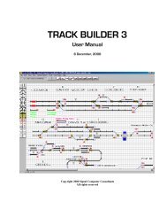
TRAIN DISPATCHER 3User <strong>Manual</strong>6 December, 2000Copyright 2000 <strong>Signal</strong> <strong>Computer</strong> <strong>Consultants</strong>All rights reserved
<strong>Train</strong> <strong>Dispatcher</strong> 3<strong>Signal</strong> <strong>Computer</strong> <strong>Consultants</strong>P.O. Box 18445Pittsburgh, PA 15236Tel. 888 872-4612 (toll free US and Canada only)Tel. 412 655-1884Fax. 412 655-1893E-mail signal@signalcc.comWeb Page www.signalcc.com<strong>Train</strong> <strong>Dispatcher</strong> 3 and Track Builder 3 are dedicated toFrank Bryan and Fred Frailey who tested both programsover a four month period and provided many suggestionson improvements.It is doubtful that these programs could have beensuccessfully completed without their help and support.Page ii6 December, 2000
<strong>Train</strong> <strong>Dispatcher</strong> 3Table of Contents1. INSTALLATION....................................................................................................................................................................................11.1. Loading the Program........................................................................................................................................................................................11.2. Starting the Program .......................................................................................................................................................................................12. WHAT’S NEW......................................................................................................................................................................................13. GETTING FAMILIAR WITH TRAIN DISPATCHER....................................................................................................................23.1. Screen Components .........................................................................................................................................................................................23.2. Track Diagram Symbols ..................................................................................................................................................................................43.3. Moving Around the Screen............................................................................................................................................................................63.4. Display Views ........................................................................................................................................................................................................63.4.1. Classic and Graphic Views .............................................................................................................................................................................63.4.2. Displaying Block Information .........................................................................................................................................................................73.5. Displaying Detailed Track and <strong>Train</strong> Information.................................................................................................................................83.5.1. Track Block Information ..................................................................................................................................................................................83.5.2. Switch Information..........................................................................................................................................................................................113.5.3. Diamond Information.....................................................................................................................................................................................134. STARTING A SIMULATION ..........................................................................................................................................................134.1. Restarting a Simulation ................................................................................................................................................................................144.2. Territory Libraries ...........................................................................................................................................................................................144.3. Changing the Territory..................................................................................................................................................................................154.4. Saving a Simulation.........................................................................................................................................................................................154.5. Opening a Previously Saved Simulation.................................................................................................................................................154.6. Loading Previous Simulation ......................................................................................................................................................................154.7. Saving the Startup Switch Positions and <strong>Signal</strong> Conditions ........................................................................................................155. MODES OF OPERATION................................................................................................................................................................155.1. Simulation (no playback) Mode..................................................................................................................................................................155.2. Simulation (with playback) Mode ..............................................................................................................................................................165.3. Playback Mode..................................................................................................................................................................................................165.4. CTC Control Mode...........................................................................................................................................................................................165.5. External I/O Mode ..........................................................................................................................................................................................166. DISPATCHING OPERATIONS......................................................................................................................................................176.1. Switch Control...................................................................................................................................................................................................176.2. <strong>Signal</strong> Control ....................................................................................................................................................................................................186.2.1. <strong>Signal</strong> Commands ...........................................................................................................................................................................................186.2.2. <strong>Signal</strong> Fleeting ...................................................................................................................................................................................................186.2.3. Running Time on a <strong>Signal</strong>.............................................................................................................................................................................196.2.4. Entrance-Exit <strong>Signal</strong> Commands...............................................................................................................................................................196.2.5. Stack Route Commands ..............................................................................................................................................................................206.2.6. Automatic <strong>Signal</strong>ing of Diamonds............................................................................................................................................................206.3. <strong>Train</strong> Speeds......................................................................................................................................................................................................216.4. <strong>Train</strong> Commands .............................................................................................................................................................................................216.4.1. <strong>Train</strong> XXX Stop Now Command................................................................................................................................................................216.4.2. <strong>Train</strong> XXX Stop in Block Command.........................................................................................................................................................216.4.3. <strong>Train</strong> XXX Start Movement Command .................................................................................................................................................226.4.4. <strong>Train</strong> XXX Clear Stop in Block XXX .........................................................................................................................................................226.4.5. <strong>Train</strong> XXX Pass Red <strong>Signal</strong> Command ..................................................................................................................................................226.4.6. <strong>Train</strong> XXX Reverse <strong>Train</strong> Command.......................................................................................................................................................226.4.7. <strong>Train</strong> XXX Change Crew Command........................................................................................................................................................226.4.8. <strong>Train</strong> XXX Merge with <strong>Train</strong> XXX Command......................................................................................................................................236.4.9. <strong>Train</strong> XXX Split Command...........................................................................................................................................................................236.5. <strong>Train</strong>s at Junctions.........................................................................................................................................................................................236.6. Permission to Enter Territory....................................................................................................................................................................236.7. Block Permit Request....................................................................................................................................................................................246.8. Crew Calling........................................................................................................................................................................................................247. SIMULATION STATUS INFORMATION ...................................................................................................................................257.1. <strong>Train</strong> Status Line..............................................................................................................................................................................................257.2. Active <strong>Train</strong> List................................................................................................................................................................................................25Page i6 December, 2000
<strong>Train</strong> <strong>Dispatcher</strong> 37.3. <strong>Train</strong> Territory Arrival Schedule ...............................................................................................................................................................277.4. <strong>Train</strong> Platform Schedule ..............................................................................................................................................................................287.5. <strong>Train</strong> Graph ........................................................................................................................................................................................................287.6. Performance Data..........................................................................................................................................................................................297.7. Active Block Permits......................................................................................................................................................................................307.8. Active Slow Orders .........................................................................................................................................................................................317.9. Alert System......................................................................................................................................................................................................328. OPTIONS..............................................................................................................................................................................................338.1. Random Performance ..................................................................................................................................................................................338.1.1. Random <strong>Train</strong> Parameters ........................................................................................................................................................................338.1.2. Random Defect Detector Parameters .................................................................................................................................................348.1.3. Random Switch and <strong>Signal</strong> Failure Parameters...............................................................................................................................358.2. Alert Options......................................................................................................................................................................................................368.3. Function Activation .........................................................................................................................................................................................389. TERRITORY DATA............................................................................................................................................................................389.1. Territory Data ...................................................................................................................................................................................................389.2. <strong>Train</strong> Type Descriptions ...............................................................................................................................................................................409.3. <strong>Train</strong> Information.............................................................................................................................................................................................419.3.1. <strong>Train</strong> Data – General Dialog ......................................................................................................................................................................439.3.2. <strong>Train</strong> Data – Multiple Entries Dialog ......................................................................................................................................................449.3.3. <strong>Train</strong> Data – Work Schedule Dialog.......................................................................................................................................................459.3.4. <strong>Train</strong> Data - Passenger Schedule Dialog..............................................................................................................................................469.4. Simulation Start Times .................................................................................................................................................................................469.5. Entrance/Exit Locations..............................................................................................................................................................................489.6. Block Permits....................................................................................................................................................................................................499.7. Slow Orders .......................................................................................................................................................................................................519.8. Wayside Detectors.........................................................................................................................................................................................529.9. OS Names...........................................................................................................................................................................................................5310. FINDING A TRAIN, TRACK, BLOCK, SWITCH, DIAMOND OR SIGNAL .......................................................................5411. TECHNICAL SUPPORT...................................................................................................................................................................5412. WARRANTY.......................................................................................................................................................................................54Page ii6 December, 2000
<strong>Train</strong> <strong>Dispatcher</strong> 3List of FiguresFigure 1 - <strong>Train</strong> <strong>Dispatcher</strong> Screen ...........................................................................................................................................3Figure 2 - <strong>Train</strong> <strong>Dispatcher</strong> Screen Bottom ..............................................................................................................................4Figure 3 - Track Symbols..........................................................................................................................................................4Figure 4 - Classic View.............................................................................................................................................................7Figure 5 - Block Speeds............................................................................................................................................................7Figure 6 - Block Lengths ..........................................................................................................................................................8Figure 7 - Track Block Status Line ...........................................................................................................................................8Figure 8 - Block Properties - General .......................................................................................................................................9Figure 9 - Block Properties - Speed ........................................................................................................................................11Figure 10 - Switch Status Line................................................................................................................................................12Figure 11 - Switch Information...............................................................................................................................................12Figure 12 - Diamond Status Line............................................................................................................................................13Figure 13 - Start Time and Day Selection...............................................................................................................................14Figure 14 - Simulation Playback Time Dialog........................................................................................................................16Figure 15 - Switch Normal and Reverse .................................................................................................................................17Figure 16 - <strong>Signal</strong> Fleeting......................................................................................................................................................19Figure 17 - Entrance-Exit <strong>Signal</strong> Commands .........................................................................................................................20Figure 18 - Crew Call..............................................................................................................................................................22Figure 19 - Diamond <strong>Train</strong> Frequency Example.....................................................................................................................23Figure 20 - <strong>Train</strong> Entry Request Dialog..................................................................................................................................24Figure 21 - Block Permit Request Dialog ...............................................................................................................................24Figure 22 - <strong>Train</strong> Status Line ..................................................................................................................................................25Figure 23 - Active <strong>Train</strong> List Window....................................................................................................................................26Figure 24 - <strong>Train</strong> OS Window ................................................................................................................................................27Figure 25 - <strong>Train</strong> Territory Arrival Window...........................................................................................................................27Figure 26 - <strong>Train</strong> Platform Schedule Window ........................................................................................................................28Figure 27 - <strong>Train</strong> Graph ..........................................................................................................................................................29Figure 28 - Performance Window...........................................................................................................................................29Figure 29 - Active Block Permit List Window .......................................................................................................................30Figure 30 - Active Slow Order List Window..........................................................................................................................31Figure 31 - Alert Messages .....................................................................................................................................................32Figure 32 - Alert Message Window ........................................................................................................................................33Figure 33 - Random <strong>Train</strong> Parameters Dialog ........................................................................................................................33Figure 34 - Random Defect Detector Parameters Dialog........................................................................................................35Figure 35 - Random Switch and <strong>Signal</strong> Failure Parameters Dialog........................................................................................36Figure 36 - Alert Parameters Dialog .......................................................................................................................................37Figure 37 - Function Activation Dialog ..................................................................................................................................38Figure 38 -Territory Data Dialog ............................................................................................................................................39Figure 39 - Territory Comments File ......................................................................................................................................39Figure 40 - <strong>Train</strong> Type Data Window.....................................................................................................................................40Figure 41 - <strong>Train</strong> Type Dialog ................................................................................................................................................40Figure 42 - <strong>Train</strong> Data Window..............................................................................................................................................42Figure 43 - <strong>Train</strong> Data - General Dialog.................................................................................................................................43Figure 44 - <strong>Train</strong> Data - Multiple Entries Dialog....................................................................................................................44Figure 45 - <strong>Train</strong> Data - Work Schedule Dialog.....................................................................................................................45Figure 46 - <strong>Train</strong> Data - Passenger Schedule Dialog ..............................................................................................................46Figure 47 - Start Times Window.............................................................................................................................................47Figure 48 - Start Time Data Dialog.........................................................................................................................................47Figure 49 - Entrance/Exit Location Window ..........................................................................................................................49Figure 50 - Block Permits Window ........................................................................................................................................50Figure 51 - Block Permit Dialog.............................................................................................................................................50Page iii6 December, 2000
<strong>Train</strong> <strong>Dispatcher</strong> 31. INSTALLATION1.1. Loading the Program<strong>Train</strong> <strong>Dispatcher</strong> 3 is a 32-bit Windows program that will run on systems running Windows 95, 98, 2000, NT 3.51 orNT 4.0 or later. It will not run under Windows 3.1.<strong>Train</strong> <strong>Dispatcher</strong> comes on a CD-ROM. To install the program, insert the CD-ROM into the CD-ROM drive and click theStart and then the Run buttons. In the Open box, type d:autorun.exe if your CD-ROM is the D drive on your computer. Ifit is not the D drive, type the appropriate drive letter followed by a colon and then autorun.exe (ex. e:autorun.exe,f:autorun.exe, etc.). Follow the instructions in the installation program to complete the installation. The Setup programwill ask you for a serial number. The serial number for <strong>Train</strong> <strong>Dispatcher</strong> 3 is the same serial number you received for<strong>Train</strong> <strong>Dispatcher</strong> and/or <strong>Train</strong> <strong>Dispatcher</strong> 2.When <strong>Train</strong> <strong>Dispatcher</strong> 3 is installed, the Setup program will load the program into the <strong>Train</strong>2 folder (default) andcreate a desktop icon.1.2. Starting the ProgramThere are four ways to start the program. To start the program:♦♦♦♦Click the Start button, point to Program, then to the <strong>Train</strong>2 folder, and click on the <strong>Train</strong> <strong>Dispatcher</strong> 3 program.Double click on the <strong>Train</strong> <strong>Dispatcher</strong> 3 icon on the desktop.Open the Windows Explorer, find the <strong>Train</strong> <strong>Dispatcher</strong> 3.exe file in the <strong>Train</strong>2 folder and double click on the file.Open the Window Explorer, find a track file (track files have a .trk file name extension) in the <strong>Train</strong>2 folder, anddouble click on the file. This will cause the <strong>Train</strong> <strong>Dispatcher</strong> 3 program to start and load the track file on whichyou clicked.After starting the program, the Track Display appears (see Figure 1).2. WHAT’S NEW<strong>Train</strong> <strong>Dispatcher</strong> 3 has been designed to meet the requirements of a major Class I railroad and also include many of thesuggestions from our <strong>Train</strong> <strong>Dispatcher</strong> 2 customers. Territories developed using Track Builder 2 can be loaded into<strong>Train</strong> <strong>Dispatcher</strong> 3; however, some of the new features require data they can only be generated by the Track Builder 3program.The following is a brief list of some of the new features of <strong>Train</strong> <strong>Dispatcher</strong> 3:♦♦♦♦♦♦♦♦♦♦Simulations can run for multiple days up to 90. (TB3 territory files only).Routes can be cleared by designating an entrance and an exit signal (Union routing).Routes can be stacked. Users can specify up to 5 stacked routes per signal that will automatically be clearedfor the next train, after the previous route has been completed or cancelled<strong>Train</strong>s can be given permission to proceed past a red signal.<strong>Train</strong>s can be merged or split into two trains.The user can request a train to stop anywhere on the territory.<strong>Train</strong>s can be reversed at any location in a block and in blocks that are used to enter or exit the territory.Helpers may be required in order for some train types to move through some blocks. (TB3 territory files only).<strong>Train</strong>s scheduled to arrive on the territory can be easily displayed by clicking on an entrance/exit location.<strong>Train</strong>s scheduled to stop at a platform can be easily displayed by clicking on a block that contains the platform.Page 16 December, 2000
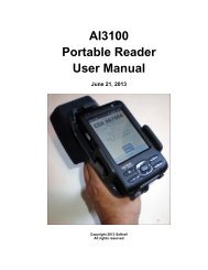
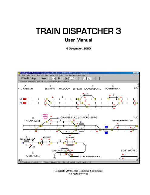
<strong>Train</strong> <strong>Dispatcher</strong> 3♦♦♦♦♦♦♦♦♦♦♦♦♦♦♦The user may be required to give permission before trains can enter the territory at designated locations. (TB3territory files only).Crews can expire because their time on duty has exceeded the 12-hour limit.The user can call crews and specify where the crew exchange will occur for a given train.Block permits and slow orders can be scheduled for different days of the week.The user must grant permission before a block permit can go into effect.Some entrance/exit locations can be designated as yard entry locations, and the user can specify how oftentrains can enter the yard (leave the territory). (TB3 territory files only).Slow orders can be made permanent.Diamonds (at grade crossings) are supported. (TB3 territory files only).Diamonds used as part of a junction with a foreign railroad can specify how often a train on the foreign railroadwith be cleared over the diamond. (TB3 territory files only).Diamonds can be set up for automatic signaling which allows conflicting routes to be cleared over the diamondat the same time. The first train that hits the approach block to the diamond gets the route. (TB3 territory filesonly).<strong>Train</strong>s can be scheduled to perform local work in designated blocks. (TB3 territory files only).<strong>Signal</strong>s can fail and require a maintainer to fix.When switches fail, the user can specify that a train crew can manually throw the switch.<strong>Train</strong> OSs are recorded and a train graph can be displayed. (TB3 territory files only).A simulation can be recorded and later played back.♦ <strong>Train</strong> schedules, block permits, and slow orders can be changed in <strong>Train</strong> <strong>Dispatcher</strong> 3.♦ <strong>Train</strong>s can develop problems (such as a broken hose).♦Locomotives can develop problems that degrade the performance of the train.<strong>Train</strong> <strong>Dispatcher</strong> 3 is an extremely realistic simulation of a dispatcher ‘s job. Because of the many enhancements, anovice user can find the simulation overwhelming. To alleviate this problem <strong>Train</strong> <strong>Dispatcher</strong> 3 allows the user to turnoff many of the optional functions. The following is a list of function that can be turned off:♦♦♦♦♦♦Slow OrdersBlock PermitsCrew CallingHelper RequirementsRequiring the user to grant permission before allowing a train to enter the territory.Limiting how often a train can enter a yard.3. GETTING FAMILIAR WITH TRAIN DISPATCHER3.1. Screen ComponentsFigure 1 shows the main <strong>Train</strong> <strong>Dispatcher</strong> screen.Page 26 December, 2000
<strong>Train</strong> <strong>Dispatcher</strong> 3ClockTimeClockStatusTimeMultiplierStatusDisplay LineFigure 1 - <strong>Train</strong> <strong>Dispatcher</strong> ScreenUnder the menu bar there is a tool button bar containing a number of items. The following describes these items inorder from left to right:♦♦♦♦♦♦♦♦♦♦♦♦♦♦Clock time - displays the game’s simulation time in 24-hour military time, the day of the week, and the numberof days since the start of the simulation.Clock status - displays the status of the simulation’s clock. “Run” indicates time is running, and “Stop” meansthe clock is stopped.“Stop” button - when clicked causes the simulation’s clock to stop.“Start” button - when clicked causes the simulation’s clock to start.Time multiplier - displays how many times faster than real time the simulation’s clock is running. If, forexample, the time multiplier is 30, the clock will run 30 times faster than normal and will, therefore, beincremented one minute for every 2 seconds of real time.“T up arrow” button - when clicked causes the time multiplier to be increased.“T down arrow” button - when clicked causes the time multiplier to be decreased.“Turn Sound Off (Turn Sound On)” - when clicked causes the sounds generated for various alerts to be turnedoff (or on if the sound is already off).“Prev Alert” button - when clicked causes the previous alert message to be displayed in the status line locatedbelow the button.“Next Alert” button - when clicked causes the next alert message to be displayed in the status line locatedbelow the button.“Go to Alert” button - when clicked causes the screen to automatically scroll to, and the mouse pointer to beplaced on, the train or block that generated the alert,“Zoom In/Out” button - when clicked zooms the track diagram either in or out depending on its current zoomstatus.“Back” button - when clicked scrolls and zooms the screen back to its previous location and zoom status.“Fwd” button - when clicked returns the screen to the location and zoom status that was displayed before the“Back” button was clicked.Under the tool button bar there is a Status Display Line that displays, depending on the location of the mouse pointer,information about trains, blocks, switches, diamonds, signals, entrance/exit locations, or alert messages. If the mousepointer is on a block that is occupied by a train, train status will be displayed. If the mouse pointer is on a switch,diamond, signal, or unoccupied block, information about that device will be displayed. If the mouse pointer is not on ablock, switch, diamond or signal, an alert message will be displayed.Page 36 December, 2000
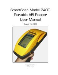
<strong>Train</strong> <strong>Dispatcher</strong> 3Track FileNamePerformanceStatus LineFigure 2 - <strong>Train</strong> <strong>Dispatcher</strong> Screen BottomAt the bottom of the screen there is a message line (see Figure 2). This message line contains the file name of thetrack territory currently being displayed and the Performance Status Line.The Performance Status Line contains the following items in left to right order:♦♦♦♦♦♦♦The number of trains currently on the territory.The total number of miles trains have traveled since the beginning of the simulation.The total number of miles all trains have traveled divided by the number of hours the simulation has beenrunning.The total amount of time trains have been stopped waiting for signals to clear and the total amount of timetrains have been stopped due to crew expirations.The total amount of time lost since the beginning of the simulation because trains were not moving at theirmaximum speed.The total amount of time since the beginning of the simulation that trains were late in departing stationplatforms.The number of times since the beginning of the simulation that trains were late departing station platforms.3.2. Track Diagram SymbolsThe track diagram has a number of symbols to represent tracks, switches, diamonds, signals, trains, etc. Many of thesesymbols are shown in Figure 3.<strong>Signal</strong>sSwitchesDiamondPlatformTrackFigure 3 - Track SymbolsPage 46 December, 2000
<strong>Train</strong> <strong>Dispatcher</strong> 3The following lists the different symbols and the meaning of the colors used to indicate their status:♦♦♦♦♦♦Straight lines drawn on the track diagram represent railroad track. The vertical or horizontal bars drawnperpendicular to the track line indicate the beginning or termination of a track block. The track is broken downinto a number of blocks. Block lengths may vary, and several trains can occupy a block at a given time.The following describes the meaning of the different track block colors:o Red - indicates a train occupies the track block. A train identifier will appear above the block that containsthe train. If the screen is in “Graphic” display mode an icon representing a locomotive is displayed on thetrack. If the train is moving in reverse an icon representing a caboose is displayed.If more than one train occupy a block, the train identifiers of the other trains in the block will be displayedbelow the track. The lead train will be above the track and the following trains will be displayed below thetrack in the order in which they are moving through the block.If any of the train identifiers are displayed in red those trains are at stop. If in blue, those trains are moving.A train may occupy more than one block at a time since a train can be longer than a block. If the programis in “Graphic” display mode a locomotive will partially overlay the block into which a train is moving and acaboose will partially overlay the block the train is leaving.Arrows will be displayed to indicate the direction in which trains are moving. Locomotive and cabooseicons may, in some cases, be displayed on top of these arrows.o Green - indicates the track block is part of a cleared route. Arrows indicate the direction of the route.o Yellow – indicates the track is part of a route that is stacked (scheduled to be automatically cleared).o Light Blue - indicates a block permit will become active in the next 30 minutes. The time at which the blockpermit will become active is displayed above the track block.o Dark Blue - indicates a block permit is active. The time the block permit will expire is displayed above thetrack block.If track blocks are blinking, they are part of a route that is running time (see Paragraph 6.2.3) and, therefore,cannot be cleared until a specified time period has elapsed.If the screen is in the “Graphic” display mode, a yellow box signifies a switch location. Switches have twopositions, which are called normal and reverse. The normal position causes the train to proceed through theswitch along the straight track as it would if there were no switch present (see Paragraph 6.1). The reverseposition causes the train to change course and move off at an angle to the straight track.The yellow box around the switch will turn light blue if the switch fails.A blinking switch indicates the user tried to clear a route that could not be cleared. Switches will also blink ifthey are part of a route that is running time (see Paragraph 6.2.3).A diamond (at grade crossing) is represented by two lines that cross each other. Diamonds will be displayed inthe same color combinations as track blocks.Any one of four different symbols can represent a signal These symbols consist of a mast and a signal ball. Ifthe signal ball is to the right of the mast, the signal controls train movement to the right and, conversely, signalswith the ball to the left of the mast control movements to the left. <strong>Signal</strong>s that have long signal masts can befleeted (see Paragraph 6.2.2), and signals with short masts cannot be fleeted.A red signal ball indicates the signal is at stop, a green ball indicates the signal is cleared for traffic to proceed,and a blue ball indicates the signal has failed. If a gray signal ball also appears, the signal is fleeted.<strong>Signal</strong>s that are blinking are running time.A signal that is the entrance signal to one or more a stacked routes will have the number of stack routesdisplayed near the base of the signal (see Paragraph 6.2.5).A station platform is represented by a gray rectangle located near the track block that contains the platform.Usually a passenger station name appears near the platform symbol.Entrance/exit location names are assigned to any track block that is not connected to another block or switch.These names are two characters long and are displayed in blue (white in the “Classic” view) at the end of thePage 56 December, 2000
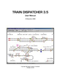
<strong>Train</strong> <strong>Dispatcher</strong> 3block that does not have a connecting switch or block. Entrance/exit locations are places where trains enterand exit the territory.3.3. Moving Around the ScreenMost territories will not completely fit on the screen when the territory is zoomed-in (old Closeup View). However, if youare using a screen with a resolution of 800 by 600 pixels, most territories designed should entirely fit on the screenwhen the territory is zoomed-out (old Overview). The Northeast Corridor territory from Washington, DC to Philadelphia,because of its size, will not entirely fit on a screen with a resolution of 800 by 600 but will fit on a screen with aresolution of 1024 by 768.There are a number of ways to move around the territory. The following lists these:♦♦♦♦♦♦Scroll using the horizontal and vertical scroll bars located at the bottom and right side of the screen.Press the “Home”, “End” “Pg Up”, “Pg Dn” or arrow keys to scroll the screen.Press a key that represents a station call up character. Each station name on the screen has a station call upcharacter assigned. These call up characters are displayed above the station names. In Figure 3 the“Analomink” station is assigned a call up character of “G”. If, for example, you press the “G” key the screen willscroll to position the “Analomink” station as close to the center of the screen as possible.Position the mouse pointer close to the edge of the screen. If the pointer is not located on a block, switch orsignal, it will turn to a solid arrow pointing in the direction the screen will scroll if you click the left mouse button.Position the mouse pointer on any grid square that does not contain a train, switch, signal, diamond or trackblock. If you click the right mouse button, the screen will zoom in or out depending on its current zoom mode,and the mouse pointer will be positioned at its location on the screen prior to the operation.Position the mouse pointer on a track at the far left or far right of the screen. If you click the left mouse buttonthe screen will scroll to, and the mouse pointer will be placed on, the track that is linked to the first track.3.4. Display Views3.4.1. Classic and Graphic ViewsThere are two display views. We have named these views “Graphic” and “Classic”. The “Graphic” view has a whitebackground and displays locomotive and caboose icons. There are yellow boxes around each of the switches, andgraphics representing objects such as bridges, rivers, buildings, etc. are displayed.Most real Centralized Traffic Control systems do not use icons to display trains. They mainly use train identifiers anddifferent colored track lines displayed on a black or dark background. <strong>Train</strong> <strong>Dispatcher</strong> 3 can simulate this type ofclassic or traditional display (see Figure 4). To display the territory in the “Classic” view click the “Classic View” itemunder the “View” menu.Page 66 December, 2000
<strong>Train</strong> <strong>Dispatcher</strong> 3Figure 4 - Classic View3.4.2. Displaying Block InformationBlocks lengths, speeds, signal directions and names can be displayed on the track diagram when in zoom-in mode. Onlyone of these items can be displayed at a given time. For blocks that are occupied by a train, have a cleared route, orhave an active block permit, no block information will be displayed. Figure 5 shows the block speeds displayed on thetrack diagram. The speeds above the track line are for trains moving to the left and below the track for train moving tothe right. The speeds displayed apply when two or more signals are cleared ahead of the block. The first number is thehighest train type speed and the second the lowest train type speed for that block.Figure 5 - Block SpeedsFigure 6 shows the block lengths in feet and miles displayed on the track diagram. Lengths are displayed in feet ormeters above the track and in miles or kilometers below the track.Page 76 December, 2000
<strong>Train</strong> <strong>Dispatcher</strong> 3Figure 6 - Block LengthsThe track diagram can be printed out at any time by selecting the “Print Track Layout Diagram” menu item under the“File” menu. The block information displayed on the screen when the track diagram is printed will also appear on theprinted copy, which can be used for reference. Block speeds, lengths, signal directions or names will not appear oneither the track diagram or a printout of the track diagram when the screen is zoomed out.3.5. Displaying Detailed Track and <strong>Train</strong> Information3.5.1. Track Block InformationWhen the user places the mouse pointer on a grid square that contains a track symbol and is not occupied by a train,the status display line located under the tool button bar at the top of the screen will display some information about thetrack block (see Figure 7).Figure 7 - Track Block Status LineThe information fields in the status line from left to right are the following:♦♦♦♦♦♦♦♦♦The track block numberThe track name or an indication that the selected block is a connecting line. Connecting lines are not realblocks and, therefore have no length. Connecting lines link switches and diamonds to real blocks.The train speeds in the block. The first two speeds are for trains moving to the left, and the second two fortrains moving to the right. These speeds apply when two or more signals are cleared ahead of the block. Thefirst number is the highest train type speed, and the second is the lowest train type speed for that block.If a slow order is active, the highest and lowest slow order speeds will be displayed instead of the normal trainspeeds for the block.The length of the block in feet (meters).The direction(s) in which the block is signaled (Left, Right or Both directions).The name of the passenger platform located in the block. If no platform is located in the block, nothing will bedisplayed.The name of the OS point assigned to the block. If no OS point is assigned, nothing will be displayed.The name of the area (work area) associated with the block. If no area is associated, nothing will be displayed.The types of the wayside detectors located in the block. Up to three detectors can be located in a block. Ifthere are no detectors in the block, nothing with be displayed.Page 86 December, 2000
<strong>Train</strong> <strong>Dispatcher</strong> 3To display more information about the track block, place the mouse pointer on the block and click the right mousebutton. If a train occupies the block, a pop-up menu will appear. Select the “Block XXX Properties” menu item andFigure 8 will appear. If a train does not occupy the block, Figure 8 will appear immediately.Figure 8 - Block Properties - GeneralData in this dialog was created via Track Builder and cannot be modified by the <strong>Train</strong> <strong>Dispatcher</strong> 3 user. The followingdescribes each of the fields in this dialog:♦♦♦♦♦♦♦♦♦♦♦Number - the unique number assigned to the block.Track name - the name of the track blockConnector - a check box to indicate whether or not the block is a connecting line that does not have length orhold trainsLeft device - the block, switch or diamond to the leftEntrance/Exit name (Left) - the entrance/exit name to the left of the block.Right device - the block, switch, or diamond to the rightEntrance/Exit name (Right) - the entrance/exit name to the right of the block<strong>Signal</strong> Direction - indicates if the block is signaled in the left and/or right direction. Usually blocks are signaledin both directions. If not, trains can only move in the direction in which the block is signaled.Block Length - the length of the block in feet, miles, meters or kilometersLeft exit control signal - the signal number of the controlled signal that allows a train moving to the left to exitthe block. If no signal number is displayed the program assumes the exit signal is automatic.Right exit control signal - the signal number of the controlled signal that allows a train moving to the right toexit the block. If no signal number is displayed the program assumes the exit signal is automatic.Normal crew change point - a check box to indicate if crews are normally changed in the blockPage 96 December, 2000
<strong>Train</strong> <strong>Dispatcher</strong> 3♦♦♦♦♦♦♦Delay in block because of crew change - the amount of time (in minutes) for the crews to change once thenew crew has arrivedTime to send crew to block - the amount of time (in minutes) it will take the new crew to get to the block afterbeing is calledPlatform name - contains the passenger platform name assigned to the block. Passenger trains that arescheduled to stop at a particular platform will stop in blocks that are assigned to the platform name. Severalblocks can be assigned to the same platform name.If a platform is not assigned to the block, “none” will be displayed in this field.Area name - contains the name of the area to which the block is assigned. Blocks can be grouped in areas.Areas are used to define locations where trains will perform local work or where trains will either become newtrains or be split into multiple trains.If the block is not assigned to an area, “none” will be displayed in this field.Wayside detectors - up to three wayside detectors can be located in a block. Wayside detectors check thetrain for problems such as hot boxes and dragging equipmentIf a wayside detector is not located in the block, “none” will be displayed in these fields.OS point - contains the OS point assigned to the block. OS points are used to create a train graph. OS pointscan be assigned to multiple blocks or switches.If an OS point is not assigned to the block, “none” will be displayed in this field.Remote monitor name - An advanced version of <strong>Train</strong> <strong>Dispatcher</strong> 3 called <strong>Train</strong> <strong>Dispatcher</strong> 3 Pro is capable ofmonitoring and controlling external devices such as real railroad ground equipment or a model railroad display.The remote monitor name is used to associate external devices to the devices in the <strong>Train</strong> <strong>Dispatcher</strong> 3display.Speeds must be assigned to the block for each different type of train for each of the three signal aspects. To display theBlock Speed dialog click the Block Speeds tab at the top of the Block Properties dialog (see Figure 8), and Figure 9 willappear.Page 106 December, 2000
<strong>Train</strong> <strong>Dispatcher</strong> 3Figure 9 - Block Properties - Speed♦BLOCK TRAIN SPEEDS - specifies the speeds of trains based on train type and the number of blocks than arecleared ahead. The system is designed to handle up to four speed aspects. If the next block is not clear, thetrain will stop when it reaches the end of the current block. If the block beyond the next is not cleared, the trainmust travel at a lower speed than its maximum in anticipation of stopping at the end of the next block.Other fields pertaining to train speeds are:o TYPE - lists the train type descriptions.oooooNONE (Left/Right Cleared Ahead Blocks) - contains the train speed in the current block if the nextblock is not cleared for the train (train will stop at the end of the current block).ONE (Left/Right Cleared Ahead Blocks) - contains the train speed in the current block if one blockbeyond the current block is cleared for the train.TWO (Left/Right Cleared Ahead Blocks) - contains the train speed in the current block if two blocksbeyond the current block are cleared for the train.HELPER - if checked indicates that the train type requires a helper for it to travel through the block.The user will have to merge a helper with the train before the train will pass into any block for which ahelper is required, even if the signal allowing the train to enter the block has been cleared.STARTUP - is the time in seconds before the train will start moving into the block if the train is at stopwaiting for the signal to be cleared.3.5.2. Switch InformationWhen the user places the mouse pointer on a grid square that contains a switch, the status display line at the top of thescreen will display some information about the switch (see Figure 10).Page 116 December, 2000
<strong>Train</strong> <strong>Dispatcher</strong> 3Figure 10 - Switch Status LineThe information fields in the status line from left to right are the following:♦♦♦The switch numberThe switch nameThe train speeds when a train goes over a switch that is in the reverse position. The highest and lowest trainspeeds of all types of trains are shown.♦ Switch failure information including the time a maintainer will arrive to fix a switch.To display more information about the switch, place the mouse pointer on the switch and click the right mouse button,and the dialog in Figure 11 will appear.Figure 11 - Switch InformationData in this dialog cannot be modified by the <strong>Train</strong> <strong>Dispatcher</strong> 3 user. The following describes each of the fields in thisdialog:♦♦♦Switch number - the unique switch number assigned to this switch.Switch name - the name of the switch.Control/monitor name – An advanced version of <strong>Train</strong> <strong>Dispatcher</strong> 3 called <strong>Train</strong> <strong>Dispatcher</strong> 3 Pro is capableof monitoring and controlling external devices such as real railroad ground equipment or a model railroaddisplay. The remote monitor name is used to associate external devices to the devices in the <strong>Train</strong> <strong>Dispatcher</strong>3 display.Page 126 December, 2000
<strong>Train</strong> <strong>Dispatcher</strong> 3♦♦♦♦♦♦OS point - contains the OS point assigned to the switch. OS points are used by <strong>Train</strong> <strong>Dispatcher</strong> 3 to create atrain graph. OS points can be assigned to multiple blocks or switches.If an OS point is not assigned to the switch, “none” will be displayed in this field.Reverse Left Block - the block, switch or diamond to the left of the switch when the switch is in the reverseposition. The switch can either have a value in the “Reverse Left Block” or “Reverse Right Block” field, but notboth. If the switch does not have a reverse left position, this field will not appear.Reverse Right Block - the block, switch or diamond to the right of the switch when the switch is in the reverseposition. The switch can either have a value in the “Reverse Left Block” or “Reverse Right Block” field, but notboth. If the switch does not have a reverse right position, this field will not appear.Normal Left Block - the block, switch or diamond to the left of the switch when the switch is in the normalposition.Normal Right Block - the block, switch or diamond to the right of the switch when the switch is in the normalposition.SWITCH REVERSE TRAIN SPEEDS - the speeds to which trains will be limited when moving over a switch thatis in the reverse position. Each type of train will travel at the indicated speed for the length of time it takes theentire train to move over the switch.If there is no speed in this field for a type of train, the train’s speed over a switch in the reverse position will notvary from its normal speed in the block.3.5.3. Diamond InformationWhen the user places the mouse pointer on a grid square that contains a diamond, the status display line at the top ofthe screen will display some information about the diamond (see Figure 12).Figure 12 - Diamond Status LineThe information fields in the status line from left to right are the following:♦The diamond number♦ The diamond name♦ If the diamond is automatically signaled (see Paragraph 6.2.6)♦The number of trains per day that automatically move left to right and right to left (top to bottom and bottom totop) across the diamond (see Paragraph 6.5)4. STARTING A SIMULATIONWhen <strong>Train</strong> <strong>Dispatcher</strong> 3 is executed the last territory used will automatically be loaded. To load another territoryselect the “Change Territory Track File” menu item under the “File” menu.To start the simulation click the “Start” button in the tool bar near the top of the screen. The first time this button isclicked after the program is executed or a new territory is loaded the Start Time and Day Selection dialog will appear(see Figure 13).Page 136 December, 2000
<strong>Train</strong> <strong>Dispatcher</strong> 3Figure 13 - Start Time and Day SelectionMost territories will have multiple start time selections. Select the start time and day to pre-load the trains that arealready on the territory at that start time. To see the list of trains already on the territory for each start time select the“Start Time” menu item under the “Data” menu.To start the simulation clock, click the “Start” button again. The clock will start and trains will begin to move.If, after you click the “Start” button, a dialog appears asking for a password, you are trying to simulate a track territoryfrom the “For Sale” library which you have not previously used. See Paragraph 4.2 for more information.4.1. Restarting a SimulationTo restart a simulation, click the “File” menu in the menu bar at the top of the screen to display a pop-up menu and thenclick the “Restart Simulation” menu item.4.2. Territory Libraries<strong>Signal</strong> <strong>Computer</strong> <strong>Consultants</strong> maintains two distinct libraries of territory track files, which we have named the“Customer Contributed” and “For Sale” libraries. As of December 2000 there were over 300 track files available. Mostof the files were created by our Track Builder customers. All track files developed with Track Builder 2 and TrackBuilder 3 can be simulated in <strong>Train</strong> <strong>Dispatcher</strong> 3.The track files (over 150) in the Customer Contributed Library are completely free and can be simulated in <strong>Train</strong><strong>Dispatcher</strong> 3. The track files (over 150) in the For Sale Library can be viewed via <strong>Train</strong> <strong>Dispatcher</strong> 3 prior to purchasebut are password protected for operational purposes. When a territory from the For Sale Library is purchased from<strong>Signal</strong> <strong>Computer</strong> <strong>Consultants</strong> a password is assigned that “unlocks” that territory for use. The first time the user clicksthe “Start” button with a “For Sale” territory loaded that has not been previously used, the system will ask for thepassword for that territory. Once a valid password is entered for the particular territory the program will not ask for itagain.Track files in both the “Customer Contributed” and “For Sale” libraries can be downloaded from our web page atwww.signalcc.com (select the “Territory Libraries” menu item under the “Web Menu” to go the territory library webpage) and are included on the <strong>Train</strong> <strong>Dispatcher</strong> 3 CD-Rom. To load these territories from the CD, insert the CD into thedrive, and a program should automatically load. If this program does not automatically load, click the “Start” button,select the “Run” menu item and then type “D:autorun.exe” where “D” is the drive identifier for your CD. If “D” is not yourCD drive, substitute the appropriate letter that identifies your CD drive. Finally click the “Ok” button to start theinstallation program.When the installation program starts, it will display buttons for loading the track territory libraries. Click on the buttonfor either the For Sale or Customer Contributed Library, which will open a WinZip Self Extracting program. If you clickthe “Unzip” button all the tracks in the library chosen will be loaded into the designated folder. If you have WinZipPage 146 December, 2000
<strong>Train</strong> <strong>Dispatcher</strong> 3installed on your computer, you can click the “Run WinZip” button to load just the territories you want. If you do not haveWinZip on your computer you can download a free evaluation copy from their web page at www.winzip.com.4.3. Changing the TerritoryThere are over 300 territories that can be simulated with <strong>Train</strong> <strong>Dispatcher</strong> 3. To change the territory to be simulated,click the “Change Territory Track File” menu item under the “File” menu. The program will display a list of territory filesthat can be opened. Each of these files has a file extension of “.trk”. Select the file to be simulated and click the “OK”button.4.4. Saving a Simulation<strong>Train</strong> <strong>Dispatcher</strong> 3 allows you to save the current simulation and restart it at a later time at the point where you left off.To save the current simulation, click the “Save Simulation As” menu item under the “File” menu. The program will askthe user to assign a file name. The file name must have an extension of “.ssm” to indicate it is a saved simulation.4.5. Opening a Previously Saved SimulationTo run a previously saved simulation click the “Open Previously Saved Simulation” menu item under the “File” menu. Aselection box will appear. Select the file to be simulated and click the “OK” button. After you have entered theappropriate day of the week, the simulation will resume where you left off and display the track diagram.4.6. Loading Previous SimulationA list of the 10 most recently used track (.trk) or previous simulation (.ssm) files will appear as menu items under the“File” menu. Simply click on one of these menu items to load the appropriate track or previous simulation file.4.7. Saving the Startup Switch Positions and <strong>Signal</strong> ConditionsAfter you have simulated a given territory several times you will notice that the initial switch positions and signalconditions you set will not vary from time to time. You will most likely always begin the simulation in the same way. It isconvenient, therefore, to save these initial switch positions and signal conditions. To save these parameters, beforeclicking the “Start” button the second time to start the simulation’s clock, set the switch positions and signal conditions,and use the “Save Simulation As” menu item under the “File” menu as described above. This action will preserve theseinitial settings to be returned to on future simulations of the territory. On future uses of the territory choose the “OpenPreviously Saved Simulation” menu item under the “File” menu instead of “Change Territory Track File.”5. MODES OF OPERATION<strong>Train</strong> <strong>Dispatcher</strong> 3 has five modes of operation. These are:♦♦♦Simulation with no playbackSimulation with playbackPlayback♦ CTC Control♦ External I/OThe mode of operation can be selected by clicking the “Mode” menu item in the menu bar. This will cause a pop-upmenu to appear with the five modes of operation listed as separate menu items. Select the appropriate menu item togo into that mode of operation. The following describes these modes of operation:5.1. Simulation (no playback) ModeThis is the normal simulation mode. <strong>Train</strong> <strong>Dispatcher</strong> 3 will simulate the territory, but will not create a playback file.Page 156 December, 2000
<strong>Train</strong> <strong>Dispatcher</strong> 35.2. Simulation (with playback) ModeThis mode allows the user to run the simulation and create a playback file. When this mode is selected, the system willfirst check to see if a simulation is running. If there is a simulation running the system will ask the user if he wants torestart the simulation. The user must select “Yes” to enter into this mode.After the user clicks the “Start” button and selects a start time, the system will then ask the user for the name of theplayback file. The file name must have an extension of “.ply” to indicate it is a playback simulation. Please note that thesystem will generate about 200 to 400 K of data for each hour of the simulation. For 24 simulated hours as much as12 MB of data will be stored in this file.The playback file allows the user to review previous simulations. <strong>Signal</strong> <strong>Computer</strong> <strong>Consultants</strong> also plans to develop ascreen saver program from a user generated playback file.5.3. Playback ModeIn playback mode the system will ask the user for the name of the playback file. After entering a playback name thesystem will display the Simulation Playback Time dialog in Figure 14.Figure 14 - Simulation Playback Time DialogThe playback of a simulation can be fast forwarded to a particular time in the simulation by entering a time and day inthe “Jump to start time” and “day of week” fields different from the simulation’s original start time and day. Once thesystem reaches the time and day specified in the “Jump to start time” and “day of week” fields, it will continue theplayback of the simulation at the speed specified in the “Time Multiplier” field in the tool bar on the main screen.During playback the user can stop and start the time clock, change the time multiplier, zoom-in or out, scroll around thedisplay and display various status windows. The user cannot throw switches or clear signals during playback. He can,however, at any time in the playback, stop the operation and place the system into the simulation without playbackmode. This allows the user to continue on with a new simulation at any point in the playback of a previous simulation.5.4. CTC Control Mode<strong>Signal</strong> <strong>Computer</strong> Consultant’s plans to develop an enhanced version of <strong>Train</strong> <strong>Dispatcher</strong> 3 called <strong>Train</strong> <strong>Dispatcher</strong> 3Pro. This enhanced version will have the ability to control and monitor wayside railroad equipment or a model railroad.In anticipation of this enhancement <strong>Train</strong> <strong>Dispatcher</strong> 3 and Track Builder 3 have already been modified to include manyof the necessary functions. For example, the remote control and monitor fields in the block, switch, and signalproperties are used to identify field hardware to the system.5.5. External I/O Mode<strong>Signal</strong> <strong>Computer</strong> Consultant’s plans to develop an enhanced version of <strong>Train</strong> <strong>Dispatcher</strong> 3 called <strong>Train</strong> <strong>Dispatcher</strong> 3Pro. This enhanced system will have the ability to drive an external CTC machine. Instead of using the mouse to clearPage 166 December, 2000
<strong>Train</strong> <strong>Dispatcher</strong> 3signals and throw switches, <strong>Train</strong> <strong>Dispatcher</strong> 3, in this mode, would get these commands from an external machine. Itwill also provide signal, switch, and track circuit conditions back to the external machine as if these conditions weregenerated by the wayside equipment.In anticipation of this enhancement <strong>Train</strong> <strong>Dispatcher</strong> 3 and Track Builder 3 have already been modified to include manyof the necessary functions. For example, the remote control and monitor fields in the block, switch, and signalproperties are used to identify field hardware to the system.6. DISPATCHING OPERATIONSThe primary job of a dispatcher is to move trains over the territory from their origin to their destination as quickly aspossible. Because the amount of track is limited, a number of trains traveling in the same and opposite directions mustoften share tracks. Part of the dispatcher’s job is determining routes that cause the most time efficient sharing of thelimited trackage. This can be a very complex task. The primary tools dispatchers have in routing trains are switchesand signals.6.1. Switch ControlSwitches allow the dispatcher to change the routes of trains. Switches have two positions, which are called normal andreverse. The normal position is for a straight move through the switch (see Figure 15). The reverse position is formovement at an angle to the original course.Normal positionReverse positionCrossover switches(corresponding)Figure 15 - Switch Normal and ReverseTo throw a switch (change its position) place the mouse pointer on the switch, which will cause a box to appear aroundthe switch, and click the left mouse button. If the switch’s position was normal prior to the operation, it will change toreverse, and vice versa.There are cases where switches will not throw. If the “Help Messages” menu item is checked (located in a pop-up menuwhich will appear when the “Help” menu in the menu bar at the top of the screen is clicked), a message will appear toexplain why the switch did not throw.The following is a list of reasons why a switch might not throw:♦♦♦The switch has a train on it (occupied).The switch has a cleared route over it.The corresponding switch cannot throw. Two switches can be tied together when they are configured as acrossover (see Figure 15). If you throw one switch, the corresponding switch will automatically throw to thesame position. If the corresponding switch cannot throw because it is occupied by a train or has a clearedroute over it, the switch that was requested to throw also will not throw.Page 176 December, 2000
<strong>Train</strong> <strong>Dispatcher</strong> 3♦The switch failed. <strong>Train</strong> <strong>Dispatcher</strong> 3 simulates random failures of switches, which often occur on realterritories. You can determine how often random failures will occur by setting parameters in the RandomSwitch and <strong>Signal</strong> Failure Parameters dialog (see Paragraph 8.1.3).6.2. <strong>Signal</strong> Control<strong>Signal</strong>s operate like highway traffic lights. <strong>Train</strong>s will not advance beyond a signal unless it is cleared (green). All signalson the track diagram have two states called stop (red) and cleared to proceed (green).Railroad signaling systems are designed to maintain safe train operations. Because it can take over a mile to stop a100-car train moving at 60 miles per hour, the locomotive engineers must rely on the signaling system. The system isdesigned to allow only one train to occupy a given track block at a given time. Each block has wayside signals that allowtrains to enter the block. Some blocks have automatic signals, which allow a train to enter the block as long as the blockis not occupied or does not have a route cleared in the opposite direction. Other blocks have controlled signals, whichare controlled by the dispatcher and appear on the track diagram. Controlled signals can be located anywhere on thetrack diagram, but are usually used to control moves over switches at interlockings.When a signal is cleared, it clears a route to the next controlled signal that is in the same direction. The route may becleared over a number of blocks and switches. The switches and blocks in a cleared route are displayed in green, witharrows showing the direction of the route.6.2.1. <strong>Signal</strong> CommandsTo change a signal’s state, place the mouse pointer on the signal, which will cause a box to appear around it, and clickthe left mouse button, which will cause the signal to go to the opposite state unless an existing condition prevents thechange.There are many safety reasons why a signal might not clear. If the “Help Messages” menu item (located in a pop-upmenu which will appear when the “Help” menu in the menu bar at the top of the screen is clicked) is checked, amessage will appear explaining why the signal did not clear and blink the switch or block that caused the problem.The following is a list of reasons why a signal might not clear:♦A route cannot be established to the next signal because a switch is open.♦ A block in the route is cleared in the opposite direction.♦ A block in the route is not signaled in the same direction as the requested route (see Paragraph 3.5.1).♦A train occupies the first block in the route.♦ A block in the route has an active block permit (Track and Time) (see Paragraph 7.7).6.2.2. <strong>Signal</strong> FleetingEach time a train advances beyond a signal, the signal will go to stop. If another train is following, the dispatcher has tore-clear the signal. A signal fleeting function is provided to help the dispatcher. This function automatically re-clears thesignal as soon as the train that initially passed the signal no longer occupies the first block beyond the signal.Only signals with long masts can be fleeted (see Figure 16). To fleet a signal, place the mouse pointer on the signal andclick the right mouse button. A pop-up menu will appear which will have a “Fleet” menu item. Select the “Fleet” menuitem, and a gray signal ball will appear next to the green signal ball to indicate the signal is now fleeted.Page 186 December, 2000
<strong>Train</strong> <strong>Dispatcher</strong> 3FleetedFigure 16 - <strong>Signal</strong> Fleeting<strong>Signal</strong>s do not have to be cleared prior to being fleeted. If the signal is at stop, <strong>Train</strong> <strong>Dispatcher</strong> 3 will automatically tryto clear it.To cancel signal fleeting, place the mouse pointer on the fleeted signal and click the right mouse button. A pop-up menuwill appear which will have a “Remove Fleet” menu item. Select the “Remove Fleet” menu item, and the gray signal ballwill disappear.6.2.3. Running Time on a <strong>Signal</strong><strong>Train</strong> dispatchers controlling a territory operating under Centralized Traffic Control are prevented from causingdangerous conditions because of safety procedures built into the system. The most dangerous thing a dispatcher cando is drop a signal (turn it red) in front of train when, from information provided by previous signals, the locomotiveengineer is not expecting to have to stop.The signaling system is designed to tell the locomotive engineer how many blocks are cleared ahead. If a locomotiveengineer suddenly sees a stop signal, when he is expecting to see a cleared one, he will probably place his train intoemergency braking to attempt to stop the train from entering the next block. Emergency braking is very dangerous andcan cause the train to de-rail.The safety system assumes the train may not come to a complete stop until it has entered the block beyond the signalat stop. The system will, therefore, not allow the dispatcher to change the switch positions in the route that was cleareduntil five minutes after the signal was dropped. The signal and route will blink on the track diagram when time is runningon a signal.The program will only run time on a signal if the block in front of the signal is occupied by a train.6.2.4. Entrance-Exit <strong>Signal</strong> CommandsTo help the dispatcher set a route faster, some dispatching offices use a system where a dispatcher specifies a route’sentrance and exit signals, and the system automatically aligns the route (positions all the switches) and clears thesignals. This eliminates the need for the dispatcher to manually position each switch before clearing the signals.<strong>Train</strong> <strong>Dispatcher</strong> 3 also has this capability. To specify an entrance-exit route place the mouse pointer on the signalwhich is the first signal in the route and click the right mouse button. A popup menu will appear that has an “Entrance”menu item. Select the “Entrance” menu item, and the signal will begin blinking. Next find the signal where you want theroute to end, place the mouse pointer on the signal, and click the left or right mouse button. If <strong>Train</strong> <strong>Dispatcher</strong> 3 canfind a path from the entrance to the exit signal it will try to clear a route. If it cannot clear the route, an appropriatemessage will appear.In Figure 17, for the indicated entrance signal you can select any signal on the second or third track from the top of thefigure as the exit signal. Even signals that are for the opposite direction can be selected. When an opposite directionsignal is selected as an exit, the route will be cleared to the next signal that is in the same direction as the route.To cancel and entrance-exit request, after selecting the entrance signal, place the mouse pointer on any place on thescreen that is not a signal and click the left mouse button.Entrance-exit requests will set up routes that go beyond just the next signal in the same direction. The system willsearch for the exit signal up to 50 devices from the entrance signal. A device is considered to be any track block,Page 196 December, 2000
<strong>Train</strong> <strong>Dispatcher</strong> 3switch, diamond or connecting line. In Figure 17 the number of devices from the entrance signal to the first signal tothe right of the entrance signal on the second track from the top of the figure is 9.Entrance <strong>Signal</strong>Figure 17 - Entrance-Exit <strong>Signal</strong> Commands6.2.5. Stack Route CommandsThere are many occasions when a dispatcher wants to clear a route as soon as a conflicting situation is resolved. Forexample, a dispatcher wants to clear a train out of siding as soon as a train moving in the opposite position clears themainline block in front of the siding Without stacking, the dispatcher has to constantly monitor the situation until thereis no longer a conflict and then clear the new route.Stacking allows the dispatcher to enter the next route to be cleared into the system. As soon as the system sees thatthere is no longer a conflict, it will automatically clear the route by positioning the switches and clearing the signal.To set up a stacked route, place the mouse pointer on the signal you want to clear next and click the right mousebutton. A pop-up menu will appear. Select the “Add Stack Command” and the signal will begin to blink in the samefashion as the entrance-exit command. Next find the signal where you want the stacked route to end, place the mousepointer on the signal, and then click the left or right mouse button. If <strong>Train</strong> <strong>Dispatcher</strong> 3 can find a path from thebeginning to the ending signal it will give you a message that the stack command was added. The stacked route will alsobe displayed in yellow. Only those portions of the route that are currently unoccupied will be shown in yellow. A numberwill also appear at the base of signal indicating the number of routes that have been stacked for that signal.Unlike entrance-exit commands, stack commands can only go to the next signal. In Figure 17, if the signal shown as theentrance signal is specified as the beginning of a stacked route, there are only two signals that could be designated asthe ending signal. These are the first signals to the right of the entrance signal on the second and third tracks from thetop of the figure.You can designate up to five stacked routes per signal. The first stacked route you enter will be the next route clearedwhen the current conflict is resolved. To see a list of stacked routes place the mouse pointer on the signal and click theright mouse button. A pop-up menu will appear which will have a “Delete Stack Command XXX (entrance signal name) –(exit signal name)” menu item for each stacked route. To close the pop-up menu, place the mouse pointer at anylocation outside the pop-up menu and click the left mouse button.To delete a stack command, select the appropriate “Delete Stack Command” menu item.6.2.6. Automatic <strong>Signal</strong>ing of DiamondsDiamonds can be automatically signaled. This means that routes can be cleared across a diamond in both directions atthe same time. If conflicting routes are cleared across a diamond the first train that hits the approach track to thediamond will be cleared to proceed across the diamond. The signals governing the diamond for the other routes willautomatically go to stop until the diamond is no longer occupied by the first train, at which time the next train to arrive atthe approach track to the diamond will be cleared to proceed.If the diamond is not set to be automatically signaled, only one route across the diamond can be cleared at any giventime.To determine if a diamond is automatically signaled, place the mouse pointer on the diamond and look at the diamond’sparameters in the Status Display line.Page 206 December, 2000
<strong>Train</strong> <strong>Dispatcher</strong> 36.3. <strong>Train</strong> SpeedsThe safety system determines the speeds trains shall travel. Because locomotive engineers usually can not see farenough ahead to know if they must soon stop, they must rely on the signaling system to tell them how fast they shouldbe going. The wayside signals will tell the engineer how many blocks ahead are cleared for his train. Most systems havethree aspects, which indicate the condition of the next two blocks. The three aspects are stop, clear to proceed throughthe next block preparing to stop at its end, and clear to proceed through the next two blocks. <strong>Train</strong> <strong>Dispatcher</strong> 3 isdesigned to handle up to four aspects, which gives the engineer information about the next three blocks.The speed a train travels through a block depends on the type of train and the number of blocks that are cleared aheadof the train. To display the train speeds for a particular block, follow the instructions in Paragraph 3.5.1.6.4. <strong>Train</strong> Commands<strong>Train</strong> <strong>Dispatcher</strong> 3 allows the user to issue commands directly to a train crew. The following is the list of commands:♦♦♦♦♦♦♦♦Stop the train nowStop the train in block XXXStart the trainClear stop train requestPass next red signalReverse the trainChange the crew in block XXXSplit train♦ Merge train with train XXXTo issue commands to a particular train, place the mouse pointer on the block that contains the train and click the rightmouse button. A pop-up menu will appear with a list of menu item representing the commands that currently can beissued to the train. If there is more than one train in the block, the commands available for each train in the block will belisted. Only currently valid commands for each train will be listed. For example, if the user has not manually stopped atrain, the “<strong>Train</strong> XXX Start Movement” menu item will not appear. If the train has been manually stopped, the “<strong>Train</strong>XXX Stop Now” will not appear.The following is a description of the train commands:6.4.1. <strong>Train</strong> XXX Stop Now CommandThe “<strong>Train</strong> XXX Stop Now” menu item command causes the designated train to stop as soon as possible. This menuitem will always appear in the pop-up menu unless this command or the “<strong>Train</strong> XXX Stop in Block” command has alreadystopped the train.Once the train is manually stopped the only way to start the train is to issue the “<strong>Train</strong> XXX Start Movement “ menu itemcommand.6.4.2. <strong>Train</strong> XXX Stop in Block CommandThe “<strong>Train</strong> XXX Stop in Block” menu item command causes the designated train to stop in the designated block. Thetrain will always stop at the far end of the block. When this menu item is selected a dialog will appear with a list ofblocks in which you can command the train to stop.Once the train is manually stopped the only way to start the train is to issue the “<strong>Train</strong> XXX Start Movement “ menu itemcommand.Page 216 December, 2000
<strong>Train</strong> <strong>Dispatcher</strong> 36.4.3. <strong>Train</strong> XXX Start Movement CommandThe “<strong>Train</strong> XXX Start Movement Now” menu item command causes the designated train to start moving as soon aspossible. This menu item will only appear in the pop-up menu if the train is stopped because the “<strong>Train</strong> XXX Stop Now”or the “<strong>Train</strong> XXX Stop in Block” commands have previously been issued for the train.6.4.4. <strong>Train</strong> XXX Clear Stop in Block XXXThe “<strong>Train</strong> XXX Clear Stop in Block XXX” menu item command causes a previous instruction to stop the train in adesignated block to be cancelled. This menu item will only appear in the pop-up menu when a train has been issued a“<strong>Train</strong> XXX Stop in Block” command.6.4.5. <strong>Train</strong> XXX Pass Red <strong>Signal</strong> CommandThe “<strong>Train</strong> XXX Pass Red <strong>Signal</strong>” menu item command causes the designated train to move past the next red signal.There are several reasons why a dispatcher may want to instruct the crew to “go through” a red signal. The two mostcommon are to allow the train to pass a signal “stuck” on red due to signal failure and to allow a train to proceed into ablock already occupied by another train traveling in the same direction. This second reason is important if two trainsare going into a merge. For example, if a train requires a helper to move up a hill, the helper would have to move past ared signal in order to get into the block that is occupied by the train needing the helper. Once in the block and stoppedbehind the other train, the helper can be connected to it by use of the “<strong>Train</strong> XXX Merge” menu item command.This menu item will only appear in the pop-up menu when a train is stopped waiting for a signal.6.4.6. <strong>Train</strong> XXX Reverse <strong>Train</strong> CommandThe “<strong>Train</strong> XXX Reverse <strong>Train</strong>” menu item command causes the designated train to stop and start movement in thereverse direction as soon as possible. This menu item will always appear in the pop-up menu unless the train has beenmanually stopped or there is another pending reverse request.<strong>Train</strong>s cannot be reversed if there is opposing traffic in the reverse direction between the train and the next controlsignal or the track behind the train is not signaled in the reverse direction.6.4.7. <strong>Train</strong> XXX Change Crew CommandThe “<strong>Train</strong> XXX Change Crew” menu item command instructs the train to stop in a designated block and wait for thenew crew to arrive. It also calls the new crew.When this menu item is selected it causes the Call Crew dialog in Figure 18 to appear.Figure 18 - Crew CallThe block in which the crew exchange is to occur must be selected. The time the new crew will arrive will be determinedby the crew’s call time entered in this dialog and the time it takes the new crew to travel to the block. The time it takesfor a crew to get to a block can be found in the Block Properties – General dialog (see Paragraph 3.5.1).Page 226 December, 2000
<strong>Train</strong> <strong>Dispatcher</strong> 3When information in the Call Crew dialog is successfully entered, the time the new crew will arrive in the block will bedisplayed. See Paragraph 6.8 for more information about the crew calling and crew time expirations.6.4.8. <strong>Train</strong> XXX Merge with <strong>Train</strong> XXX CommandThe “<strong>Train</strong> XXX Merge with <strong>Train</strong> XXX” menu item command causes the designated train to merge with another train.This menu item will appear in the popup menu when the designated train is behind another train in the same block andboth trains are stopped.Once two or more trains are merged together, they can be split apart by the “<strong>Train</strong> XXX Split” command.6.4.9. <strong>Train</strong> XXX Split CommandThe “<strong>Train</strong> XXX Split” menu item command causes the designated train to be split into two trains. This menu item willappear in the popup menu when the designated train has been previously merged with another train.When this menu item is selected a dialog will appear which asks which train is to be split from the designated train.6.5. <strong>Train</strong>s at JunctionsDiamonds are often used at junctions with a foreign railroad. <strong>Train</strong>s moving across the junction are often controlled byanother railroad and can have a serious impact on dispatching operations.<strong>Train</strong> <strong>Dispatcher</strong> 3 simulates the impact of these trains by specifying how often a train controlled by another dispatcherwill cross the junction. Diamonds that are partially controlled by another dispatcher do not have any signals in the routeacross the diamond that the other dispatcher controls. In Figure 19, another dispatcher controls the route thatcrosses the diamond at Branchville from top to bottom.Figure 19 - Diamond <strong>Train</strong> Frequency ExampleTo display the frequency of foreign trains across the diamond, place the mouse pointer on the diamond. The trainfrequency over the diamond will appear in the status display line. In this case <strong>Train</strong> <strong>Dispatcher</strong> 3 would automaticallyclear and move 2 trains a day across this junction. Each train’s route would be cleared 5 to 15 minutes before the trainarrived and be occupied for 2 to 5 minutes.6.6. Permission to Enter TerritoryA number of entrance/exit locations require the dispatcher to give the train permission before it can enter the territory.To determine if an entrance/exit location requires trains to obtain permission before entering the territory, place themouse pointer on the entrance/exit location name. The status display line will display information about theentrance/exit location including whether trains must obtain permission to enter the territory at that location.Page 236 December, 2000
<strong>Train</strong> <strong>Dispatcher</strong> 3When a train requests permission to enter the territory the dialog in Figure 20 will appear.Figure 20 - <strong>Train</strong> Entry Request DialogThe request can either be granted for a specified time or can be delayed until later. If delayed, the train will makeanother request in 30 minutes.The train entry request function can be de-activated. See Paragraph 8.3 about turning off this function.6.7. Block Permit RequestTracks often require maintenance. Before maintenance can be performed, the track must be taken out of service. Totake a track out of service, the dispatcher issues a block permit (track & time). The block permit authorizes amaintenance gang to work on the track for a specified amount of time.When a foreman wants to obtain a block permit he will issue a request to the dispatcher. When a request is made in<strong>Train</strong> <strong>Dispatcher</strong> 3, the dialog in Figure 21 will appear.Figure 21 - Block Permit Request DialogThe dispatcher can either ask the foreman to request the permit again or authorize it for a specific time period. If theforeman is not granted time, he will make another request in 30 minutes.If time is granted, but not for the total amount requested, the foreman will make another request after the first permitthat was granted has expired.6.8. Crew Calling<strong>Train</strong> crews are only allowed to be on duty for 12 hours. If a train crew’s on-duty time exceeds 12 hours (crew‘s timeexpires), the train will stop and will not move again until a new crew arrives and replaces the current train crew.It is the job of the dispatcher to call replacement crews and to prevent train crews from expiring on the mainline.Page 246 December, 2000
<strong>Train</strong> <strong>Dispatcher</strong> 3The time a train’s crew will expire can be found in the Active <strong>Train</strong> List window (see Paragraph 7.2) or in the train’sstatus line display at the top of the screen, which is seen when the mouse pointer is positioned on the block containingthe train.A new crew for a train can be called at anytime and be scheduled to replace a train’s crew at a platform or in aspecified block. The time it takes for a crew to arrive at a platform or block is determined by the time the crew wascalled plus the travel time to the block. There is a field in each block’s Block Properties – General dialog that containsthe amount of time it takes to get a new crew to the block.A crew’s on-duty time starts when the dispatcher calls the crew.7. SIMULATION STATUS INFORMATION<strong>Train</strong> <strong>Dispatcher</strong> 3 provides a considerable amount of information about the status of a simulation. Most of thisinformation is centered around the status of trains, but also addresses block permits and slow orders. The followingdescribes various functions that provide status information.7.1. <strong>Train</strong> Status LineTo quickly find information about a train, place the mouse pointer on the train. The train’s status will appear in thestatus display line near the top of the screen (see Figure 22)Figure 22 - <strong>Train</strong> Status LineThe train status line contains the following information:♦♦♦♦♦♦♦♦The train identifierThe average speed of the train in the blockThe length of the trainThe next entrance/exit location where the train is to leave the territory or the train identifier of the trainthis train will becomeThe status of the train (i.e. “moving forward”);The train’s next scheduled evento if the train is moving, the time it will arrive at the end the blocko if the train is at stop waiting for a signal, the time it stoppedo for all other train stops (platform, work area, etc.), the estimated time of departure.The time when the crew will expire because they have worked 12 hours.If a new crew has been called, the place and time the crew change will occur7.2. Active <strong>Train</strong> List<strong>Train</strong>s that are on the territory and are due to arrive on the territory in 8 hours appear in the Active <strong>Train</strong> List window.To call up the Active <strong>Train</strong> List window, select “<strong>Train</strong>s" in the menu bar, and the display in Figure 23 will appear.Page 256 December, 2000
<strong>Train</strong> <strong>Dispatcher</strong> 3Figure 23 - Active <strong>Train</strong> List WindowThis window is dynamically updated. As trains move and their status change, the window will be modified to reflectthese changes. To stop this window from updating click the “Stop” button to stop the simulation clock.The list can be sorted by train identifier, train status or by estimated time of arrival/departure (ETA). To sort by trainidentifier, status, or ETA click the “Sort ID”, “Sort Status” or “Sort ETA” buttons, respectively.To display only the trains that are scheduled to arrive on the territory, are stopped, are moving, or are off the territoryand will not return, check the “Arriving”, “Stopped”, “Moving” or “Completed” boxes, respectively.The user can re-size any of the columns in this window by placing the mouse on a vertical separator in the columnsheader and, while holding down the left mouse button, drag the mouse to the left or right. Once the columns are resized,the user can save the column widths for the next time the window is displayed by clicking the “Save ColumnWidths” button.The following describes each of the columns in this window:♦♦♦♦♦♦♦♦♦♦♦♦♦<strong>Train</strong> ID - contains the train identifier.Status - contains a text description of the train’s current status.Length - contains the train length in feet/meters.Type - indicates the type of train.Location - contains the name of the track where the train is currently located.Direction - indicates the train’ s current direction.Speed - the average speed in which the train is moving in the current block.ETA - the following describes the contents of this fieldo if the train is moving, the time it will arrive at the end the blocko if the train is scheduled to arrive, the time it will arrive on the territoryo if the train is at stop waiting for a signal, the time it stoppedo for all other train stops (platform, work area, etc.), the estimated time of departure.Crew Expiration - the time the crew will expire because it was on duty for 12 hours.Entrance - contains the entrance/exit location where the train came onto the territory the last time.Exit - contains the entrance/exit location where the train should exit the territory.Next Station Stop/Time - contains the name of the next station platform and the time the train is scheduled tostop at the platform.Part of <strong>Train</strong> – if the train is merged with another train, the train identifier of the merged train.Page 266 December, 2000
<strong>Train</strong> <strong>Dispatcher</strong> 3To locate a train on the territory, place the mouse pointer on any of the data contained in a train’s row, click the left orright mouse button to select the train, and then click the “Find” button. <strong>Train</strong> <strong>Dispatcher</strong> 3 will then scroll on theterritory screen to the location of the train and place the mouse pointer on the train.The train’s data dialog can be called up by placing the mouse pointer on any data contained in a train’s row, clicking theleft or right mouse button to select the train, and then clicking the “Properties” button.<strong>Train</strong> <strong>Dispatcher</strong> 3 keeps a record of train movements by recording the time a train passes an OS point (OS issometimes referred to as on-station or out of station).OS point names are usually assigned to the switches at each end of a siding or to blocks in the middle of a siding. Thenumber and location of the OS points are determined by the railroad. A list of the OS points can be called up byselecting the “OS Points” item under the “Data” menu.The train’s OS window can be called up by placing the mouse pointer on any data contained in a train’s row, clicking theleft or right mouse button to select the train, and then clicking the “OS” button. Figure 24 shows the <strong>Train</strong> OS window.Figure 24 - <strong>Train</strong> OS Window7.3. <strong>Train</strong> Territory Arrival ScheduleA list of trains that are to arrive on a territory at a given entrance/exit location can be called up placing the mousepointer on the entrance/exit location name and clicking the right mouse button. Figure 25 will then appear.Figure 25 - <strong>Train</strong> Territory Arrival WindowThis window shows the trains that will arrive on the territory in the next eight hours. The trains are sorted by theirarrival time.The user can re-size any of the columns in this window by placing the mouse on a vertical separator in the columnsheader and, while holding down the left mouse button, drag the mouse to the left or right. Once the columns are re-Page 276 December, 2000
<strong>Train</strong> <strong>Dispatcher</strong> 3sized, the user can save the column widths for the next time the window is displayed by clicking the “Save ColumnWidths” button.The train’s data dialog can be called up by placing the mouse pointer on any data contained in a train’s row, clicking theleft or right mouse button to select the train, and then clicking the “Properties” button.Multiple <strong>Train</strong> Territory Arrival windows for different entrance/exit locations can be opened at the same time. Thesewindows will automatically update as the status of trains change.7.4. <strong>Train</strong> Platform ScheduleA list of trains scheduled to stop at a platform can be called up placing the mouse pointer on a block containing theplatform and clicking the right mouse button. Click on the “<strong>Train</strong> Stop at Platform” item in the pop-up menu that willappear, and the window shown in Figure 26 will be displayed.Figure 26 - <strong>Train</strong> Platform Schedule WindowThis window shows the trains that will be stopping at the platform in the next eight hours. The trains are sorted by theirscheduled platform departure time.The user can re-size any column in this window by placing the mouse on a vertical separator in the columns header and,while holding down the left mouse button, drag the mouse to the left or right. Once the columns are re-sized, the usercan save the column widths for the next time the window is displayed by clicking the “Save Column Widths” button.To locate a train on the territory, place the mouse pointer on any of the data contained in a train’s row, click the left orright mouse button to select the train, and click the “Find” button. <strong>Train</strong> <strong>Dispatcher</strong> 3 will then scroll on the territoryscreen to the location of the train and place the mouse pointer on the train.The train’s data dialog can be called up by placing the mouse pointer on any data contained in a train’s row, clicking theleft or right mouse button to select the train, and then clicking the “Properties” button.7.5. <strong>Train</strong> GraphA historical record of train movements can be displayed in the form of a train graph. The train graph is a graphicalrepresentation of train movements obtained by plotting the time each train hits an OS point. To display the train graphselect the “Display <strong>Train</strong> Graph" item under the “View” menu (see Figure 27).Page 286 December, 2000
<strong>Train</strong> <strong>Dispatcher</strong> 3Figure 27 - <strong>Train</strong> GraphThe train graph plots each train. The OS points are indicated on the left side of the display and time across the top.Dots indicate when an actual OS time was recorded for the train. Each train is assigned a color, and the train’sidentifier is displayed above alternating OS hits.To change the size of the train graph, modify the pixel widths in the “OS Spacing” (height) and “Hour Spacing” (width)fields at the top of the screen, and then click the “Resize” button.7.6. Performance DataThe performance of individual trains can be monitored. To view train performance, select the “Display Performance”item under the “View” menu, and the window shown in Figure 28 will appear.Figure 28 - Performance WindowPage 296 December, 2000
<strong>Train</strong> <strong>Dispatcher</strong> 3This window displays the total performance of the system (first row) and the individual performance of each train. Thetrain performance is sorted by the train identifier. The following describes the columns in this window:♦♦♦♦♦♦♦<strong>Train</strong> ID - the train identifier.Miles - the total number of miles the train has traveled.Stop Time - the amount of time the train has been stopped either waiting for a signal to clear or due to crewexpiration.Lost Time - the amount of time that was lost because the train was not moving at its maximum speed.Late Departure Time - the amount of time the train was late in departing station platforms.Late Departure - the number of times the train was late departing station platforms.Missed Exits – the number of times the train departed the territory at the wrong entrance/exit location.7.7. Active Block PermitsBlock permits that are active, authorized by the dispatcher and not active, or to be requested within 8 hours (pending)can be viewed in the Active Block Permit List window. To call up the Active Block Permit List window select the “Permit"item in the menu bar, and the window in Figure 29 will appear.Figure 29 - Active Block Permit List WindowThis window is dynamically updated. As the status of block permits change, the window will continually be modified toreflect these changes.The list can be sorted by track name or the permit’s requested or actual start time. To sort by the track name or thepermit’s requested or actual start time click the “Sort Track” or “Sort Time” buttons, respectively.To display just the block permits that are pending, authorized or active, check the “Pending”, “Authorized” or “Active”boxes, respectively.The user can re-size any column in this window by placing the mouse on the vertical separator in the columns headerand, while holding down the left mouse button, drag the mouse to the left or right. Once the columns are re-sized, theuser can save the column widths for the next time the window is displayed by clicking the “Save Column Widths” button.The following describes each of the columns in this window:♦♦♦♦♦Number - contains the internal system number of the permit.Status - contains the status of the permit.Track Name - contains the name of the track that will be protected by the permit.From Time - contains the requested or actual time the permit will start.To Time - contains the requested or actual time the permit will end.Page 306 December, 2000
<strong>Train</strong> <strong>Dispatcher</strong> 3♦♦Time Still needed - the amount of time the requestor still needs after the currently authorized or active permitends.Requestor - the name of the person requesting the block permit.♦ Reason - the reason for the request.To authorize a pending block permit request, place the mouse pointer on any of the data contained in a block permit’srow, click the left or right mouse button to select the block permit, and click the “Authorize” button. The Block PermitRequest dialog in Figure 21 will then appear.7.8. Active Slow OrdersSlow orders that are active or will occur within 8 hours (pending) can be viewed in the Active Slow Order Permit Listwindow. To call up the Active Slow Order List window select the “Slow Order" menu item in the menu bar, and thewindow in Figure 29 will appear.Figure 30 - Active Slow Order List WindowThis window is dynamically updated. As the status of slow orders change, the window will be continually modified toreflect the changes.The list can be sorted by track name or the slow order’s requested or actual start time. To sort by the track name orthe slow order’s requested or actual start time, click the “Sort Track” or “Sort Time” buttons, respectively.To display only the slow orders that are pending or those that are active, check the “Pending” or “Active” boxes,respectively.The user can re-size any of the columns in the window by placing the mouse on a vertical separator in the columnsheader and, while holding down the left mouse button, drag the mouse to the left or right. Once the columns are resized,the user can save the new column widths for the next time the window is displayed by clicking the “Save ColumnWidths” button.The following describes each of the columns in this window:♦♦♦♦♦Number - contains the internal system number of the slow order.Status - contains the status of the slow order.Track/Block/Switch Name - the name of the track, block or switch that is affected by the slow order.Permanent – indicated if the slow order is permanent or has a limited time period.From Time - the time when the slow order goes into effect.Page 316 December, 2000
<strong>Train</strong> <strong>Dispatcher</strong> 3♦♦To Time – the time the slow order expires.Slow Order Speeds – is a group of fields for each type of train in each direction, which contains the maximumspeeds the trains can travel over the track, block or switch when the slow order is in effect. If the speed for atrain type is blank, the slow order does not affect the speeds for that type of train.7.9. Alert SystemCentralized Traffic Control systems generally allow dispatchers to view their entire territories at one time by usingseveral monitors or a wall board. Because most computers only have one monitor, <strong>Train</strong> <strong>Dispatcher</strong> 3 cannot, in somecases, display the entire territory on a single screen even if the track diagram is zoomed out and the monitor is set at itshighest resolution.To help the user, <strong>Train</strong> <strong>Dispatcher</strong> 3 has a message alert system, which informs the user of situations that may requirehis or her attention. The system can generate an alert message for any of the following situations:♦♦♦♦♦♦♦♦♦When a train arrives on the territoryWhen a train is stopped waiting at a signalWhen a train is stopped because of a wayside defect detector alarmWhen a block permit will become active in 30 minutesWhen a block permit becomes activeWhen a slow order becomes activeWhen a train is late arriving at a passenger stationWhen a train has locomotive problems which affect the train’s performanceWhen a train is having problems that require it to stop♦ When a train’s crew will expire in two hours♦ When a train’s crew expiresThe user can decide which alert messages will be generated and whether they will have an associated audio alarm (seeParagraph 8.2).Alert messages will appear in the status line near the top of the screen (see Figure 31) if the mouse pointer is notplaced on a train, track block, switch, diamond, or signal. If the mouse pointer is on any one of these items, instead ofthe alert message, information on that item will be displayed in the status line.Figure 31 - Alert MessagesThe alert displayed in the status line is either the last alert that occurred or the last alert the user looked at. To set thisoption to be the last alert that occurred, select the “Display Last Alert” menu item under the “View” menu.There are three buttons located above the status line that are associated with the alert system. These are the “PrevAlert”, “Next Alert” and “Go to Alert”. The program saves a list of the 50 most recent alert messages. Each alertmessage is assigned a sequential number. If there is an alert message after the one that is currently being displayed inthe status line, the “Next Alert” button will be active (not gray). To display the next alert message, click the “Next Alert”button. If there is an alert message previous to the one being displayed, the “Prev Alert” button will also be active.Clicking on the “Go to Alert” button will cause the mouse pointer to be positioned on the territory screen at the location(train or track block) that caused the alert condition displayed in the status line.Page 326 December, 2000
<strong>Train</strong> <strong>Dispatcher</strong> 3The alert system can also display a window that shows all 50 of the alert messages currently saved in the system. Todisplay the Alert Message window (see Figure 32), click on the “Display Alert Window” item in the “View” menu. Thealert that is displayed in the status line will be highlighted in the window that appears. To go from this window to thedevice that caused the alert message double click (using the left mouse button) on the message.Figure 32 - Alert Message Window8. OPTIONS<strong>Train</strong> <strong>Dispatcher</strong> 3 has a number of options that can be selected to vary a simulation. These options are broken downinto three categories. These categories specify the randomness of a simulation, the alert parameters, and whichfunctions are to be active.8.1. Random PerformanceTo make each simulation different and more realistic, a random performance generator is included in <strong>Train</strong> <strong>Dispatcher</strong>3. The user controls the effect of the random performance generator by entering various parameters. There are threetypes of random performance parameters: train; wayside defect detector; and switch and signal.8.1.1. Random <strong>Train</strong> ParametersTo enter the train parameters for the random performance generator, select the “Random <strong>Train</strong> Parameters” menuitem under the “Random” menu. Figure 33 will appear.Figure 33 - Random <strong>Train</strong> Parameters DialogFor each train type the user can define a range of randomness for performance, delays, and failures. The followingdescribes each of the fields in the Random <strong>Train</strong> Parameters dialog:Page 336 December, 2000
<strong>Train</strong> <strong>Dispatcher</strong> 3♦♦♦♦♦♦Run Time Performance - Even though the signaling system and operating rules dictate how fast a train shouldtravel, locomotive engineers operate differently. This parameter sets by how much train speed will deviate fromexpected speed. If this field is set to 10, for example, the trains’ speeds will deviate +-10% from the expectedspeed. A train, therefore, with an expected speed of 60 miles per hour will be assigned a random speedbetween 54 and 66 miles per hour. If this parameter is set to zero, the trains will always travel at the expectedspeeds.The random speed deviation for a particular train type applies from the time it enters the territory until it existsthe territory. Therefore, a train will travel through all blocks at the same percentage deviation from theexpected speed.Startup Delays - Stopped trains do not always immediately start to move when a signal is cleared. The trainstartup time can be affected by the weight of the train, the slope of the track, and the locomotive engineer’sresponse time. When this parameter is checked, a random startup time for the train will be generated basedon the normal start up time for that train type.Late train arrival - <strong>Train</strong>s will not always arrive on the territory at the scheduled time. This parameter sets thepercentage of trains that will be late arriving on the territory. If this parameter is set to zero, all trains willarrive on the territory on time.The amount of time a train can be late deviates from 1 minute to 9 hours and 59 minutes. The algorithm usedto calculate the lateness of a train causes lower time delays to be assigned more often than higher ones. Forexample, 50% of all time delays will be less than one hour, 75% less than 2 hours, 87.5% less than 3 hours,etc.Locomotive Problems – <strong>Train</strong>s can have problems with one or more of their locomotives that will affect theperformance of the train. The number entered into this parameter indicates the percentage of trains on theterritory that will have locomotive problems. For example, if this parameter set to 0, none will; if it is set to 50,then 50 percent of the trains will develop locomotive problems.<strong>Train</strong> Problems – <strong>Train</strong>s can have problems such as broken air hoses. When a problem of this type occursthe train must stop and the crew will have to fix the problem before it can move again. As above, the numberentered into this field indicates the percentage of trains on the territory that will have this type of problem.Dropped <strong>Signal</strong> Derailment - One of the most dangerous things a train dispatcher can do is drop a signal(abruptly change the signal from cleared to stop) in front of a moving train. This parameter determines thepercentage of trains moving at speeds greater than 35 miles per hour that will be de-railed if the dispatcherdrops a signal in front of them. For trains traveling less than 35 miles per hour, the percentage that will de-railwill be half of this parameter. <strong>Train</strong>s already stopped when a signal is dropped will obviously not be de-railed.Derailed trains will be stopped for a period of between 2 and 10 hours.8.1.2. Random Defect Detector ParametersTo enter the defect detector parameters for the random performance generator, select the “Random Defect DetectParameters” item under the “Random” menu. Figure 34 will appear.Page 346 December, 2000
<strong>Train</strong> <strong>Dispatcher</strong> 3Figure 34 - Random Defect Detector Parameters DialogFor each type of wayside defect detector the user can define a range of randomness for alarms and false alarms. Thefollowing describes each of the fields in the Random Defect Detector Parameters dialog:♦♦Alarms - A number of track blocks may contain wayside defect detectors. <strong>Train</strong>s passing through these blockswill be scanned for problems and an alarm will be generated if a problem is detected. This parameterdetermines the number of times a problem be detected for every 1000 trains scanned. If an alarm isgenerated the crew will stop the train, walk to the car that is the subject of the alarm, and determine if thealarm was real or false. This process will cause the train to be stopped for a period of time based on thedistance from the front of the train to the car that caused the alarm.False Alarms - Not all alarms are real. A number of them are false. This parameter sets the percentage ofalarms that are false. If the alarm is false, the train will restart immediately after the car is checked. If thealarm is real, the train will be stopped for an additional period of time while the crew corrects the problem.8.1.3. Random Switch and <strong>Signal</strong> Failure ParametersTo enter the switch and signal failure parameters for the random performance generator, select the “Random Switchand <strong>Signal</strong> Failure Parameters” item under the “Random” menu. Figure 35 will appear.Page 356 December, 2000
<strong>Train</strong> <strong>Dispatcher</strong> 3Figure 35 - Random Switch and <strong>Signal</strong> Failure Parameters DialogThe user can define a range of randomness for switch and signal failures. The following describes each of the fields inthe Random Switch and <strong>Signal</strong> Failure Parameters dialog:♦♦♦♦Switch failures - Switches sometimes fail to throw because of mechanical problems or debris located near theswitch points. This parameter determines the number of switch failures that will occur for every 1,000 switchthrows. If a switch fails to throw, the dispatcher will make several attempts to throw it again and hope themovement of the points will dislodge any debris. <strong>Train</strong> <strong>Dispatcher</strong> 3 is designed to recover from a switch failure50% of the time on the first attempted throw after the switch failure, 25% on the second attempted throw,12.5% on the third throw, etc. The user will be asked if a maintainer should be called to correct the problem.The user can also tell the crew of a train stopped near the switch to manually throw the switch. To request acrew to manually throw a switch, place the mouse pointer on the failed switch and click the right mouse button.This will cause a pop-up menu to appear with a “Crew to throw Switch XXX <strong>Manual</strong>ly” menu item. Select thismenu item to throw the switch in the opposite direction.Please note that this menu item will not appear if there is no train stopped near the switch.<strong>Signal</strong> failures – <strong>Signal</strong>s will sometimes fail to clear. This parameter determines the number of signal failuresthat will occur for every 1,000 attempts to clear the signal. If a signal fails to clear, the dispatcher will makeseveral attempts to clear it again. <strong>Train</strong> <strong>Dispatcher</strong> 3 is designed to recover from a signal failure 50% of thetime on the first attempt to clear after the signal failure, 25% on the second attempted throw, 12.5% on thethird throw, etc. The user will be asked if a maintainer should be called to correct the problem.While waiting for a maintainer to fix a signal stuck on red, the user can allow trains to pass the failed signal.For more about this see Paragraph 6.4.5.Time for maintainer to arrive – It takes a certain amount of time for a maintainer to arrive and fix the problem.In this field the user specifies, in minutes, this amount of time.Random maintainer arrival time – The amount of time it takes for a maintainer to arrive and fix a problem isnot always constant. This field allows the user to specify limits on the randomness of the arrival time. If 50% isentered into this field and the maintainer’s arrival time is 2 hours, then the random arrival time will be between1 and 3 hours.8.2. Alert OptionsThere are a number of alert messages that can be activated or de-activated by the user. The user can select whichalert messages are active and if they will produce an audio alarm. The audio alarm can either use the computer’sinternal bell or a sound card. To select the alert options, click the “Alert Parameters” item under the “Options” menu.Figure 36 will appear.Page 366 December, 2000
<strong>Train</strong> <strong>Dispatcher</strong> 3The following describes the fields in this dialog:♦♦♦Figure 36 - Alert Parameters DialogAlerts - Each type of alert message can be turned on or off by clicking the appropriate “Yes” check box. If the“Yes” box is checked for a particular alert message, an alert message will be issued any time the conditionexists. For any alert message conditions that do not have the “Yes” box checked, alert messages will not beissued.Bells - Sounds can also be generated when an alert message is issued. If the computer’s internal bell is used,a number greater than zero should be entered in the appropriate “Bell” field indicating how many times a bellwill chime as an alert to the dispatcher of the alert condition.Please note that sometimes the internal bell is turned off if the computer has a sound card installed. Pleaserefer to your computer’s setup function (not the Window’s Setup function) if the internal bell fails to sound.Please also make sure that the sound in <strong>Train</strong> <strong>Dispatcher</strong> 3 is turned on by clicking the “Turn on Sound” buttonin the toolbar near the top of the screen.Sound File - If a sound card is installed in the computer, unique sounds for each alert condition can begenerated by entering a wave file name (files with an extension of “.wav”) in the “Sound File” field.If the computer has a sound card, a number of wave files are usually provided by one of the vendors and arelocated in the windows or windows/media folder. To find these files, use the “Browse” button next to the“Sound File” field.If you cannot find any .wav files, click the Window’s “Start” button, select the “Find” menu item, select the “Filesor Folders” menu item, enter “*.wav” in the “Named” field and click the “Find Now” button. A list of .wav filesshould appear and indicate in which folders they reside on the disk.With a sound card, users can also generate their own sound files that contain verbal messages (check thedocumentation which accompanied the sound card for more information).Page 376 December, 2000
<strong>Train</strong> <strong>Dispatcher</strong> 3♦Late station departure – the user can also specify, in this dialog, how many minutes beyond a scheduleddeparture time a train can fail to depart a platform before an alert is generated.8.3. Function Activation<strong>Train</strong> <strong>Dispatcher</strong> 3 tries to accurately simulate a dispatcher’s operation. This can sometimes be overwhelming to anovice. To make it simpler to simulate a territory, <strong>Train</strong> <strong>Dispatcher</strong> 3 allows the user to turn off various functions.To activate or de-activate these optional functions, click the “Function Activation” menu item under the “Options” menu.Figure 37 will appear.Figure 37 - Function Activation Dialog9. TERRITORY DATAThe user can view data in a loaded track territory file by selecting one of the menu items under the “Data” menu. A<strong>Train</strong> <strong>Dispatcher</strong> 3 user can also modify some data in the track file. The <strong>Train</strong> <strong>Dispatcher</strong> 3 user can modify train, blockpermit, and slow order data. Data about the track structure or speed restrictions cannot be changed.If the user changes track file data, a new track file can be created that contains the user changes. To save a modifiedtrack file, select the “Save Territory Track File” menu item under the “File” menu. This action will not overwrite theoriginal track file.The following describes the various track file data areas:9.1. Territory DataData about the territory that can be viewed by the users is included in <strong>Train</strong> <strong>Dispatcher</strong> 3. To view this information,select the “About Territory” item under the “Data” menu in the menu bar. Figure 38 shows the dialog this menuselection produces.Page 386 December, 2000
<strong>Train</strong> <strong>Dispatcher</strong> 3Figure 38 -Territory Data Dialog<strong>Train</strong> <strong>Dispatcher</strong> 3 does not have the “Comments” field that was in <strong>Train</strong> <strong>Dispatcher</strong> 2. To provide greater flexibilityTrack Builder 3 users can attach a comments file to the track file. When <strong>Train</strong> <strong>Dispatcher</strong> 3 loads a track file itgenerates the comments file. This file is a text file (.txt file extension) and can be generated by any word processingapplication or Window’s NotePad or WordPad programs.To open the comments file, click the “Open” button, and the NotePad program will start and display the comments file.A sample of what this display might look like is shown in Figure 39,Figure 39 - Territory Comments FilePage 396 December, 2000
<strong>Train</strong> <strong>Dispatcher</strong> 39.2. <strong>Train</strong> Type Descriptions<strong>Train</strong>s can be designated as one of ten types. To view the train types select the “<strong>Train</strong> Type Description” item under the“Data” menu in the menu bar at the top of the screen. The <strong>Train</strong> Type Data Window in Figure 40 will appear.Figure 40 - <strong>Train</strong> Type Data WindowThis window displays information about all of the train types. The user can re-size any column in this window by placingthe mouse on a vertical separator in the columns header and, while holding down the left mouse button, drag the mouseto the left or right. Once the columns are re-sized, the user can save the column widths for the next time the window isdisplayed by clicking the “Save Column Widths” button.To edit a train type, first place the mouse pointer on the train type row and click the left button to select (highlight) thetrain type. Then click the “Edit” buttons. The “Edit” button will cause the <strong>Train</strong> Type dialog to appear (see Figure 41).You can also place the mouse on the train type row and click the right mouse button, which will also cause the <strong>Train</strong>Type dialog to appear.The only fields that can be changed in this dialog are the “Locomotive left bitmap file”, the “Locomotive right bitmap file”and the “Caboose bitmap file” fields.The following describes each of the fields in the dialog:♦♦♦Description – a description of the train type.Type – a system description of the train type.Figure 41 - <strong>Train</strong> Type DialogCabs at each end of train – is a check box that indicates the train has cabs on both ends and, therefore, hasequal performance in both directions. In <strong>Train</strong> <strong>Dispatcher</strong> 3 these trains are never considered to be moving ina reverse direction. <strong>Train</strong>s that have dual cabs are usually transit vehicles or passenger trains.Page 406 December, 2000
<strong>Train</strong> <strong>Dispatcher</strong> 3♦♦♦♦Startup time – is the time it takes to get a train started if it was stopped waiting for a signal. This field is usedto assign for the train type the default startup time that appears in the Block Properties - Speeds dialog (seeFigure 9).Reverse speed – is the maximum speed of the train when it is moving in reverse.Locomotive left bitmap file – custom icons can be added to the track execute file in <strong>Train</strong> <strong>Dispatcher</strong> 3. Theseicons are created from bitmap files that have a bitmap representing a left facing locomotive, a right facinglocomotive, or a caboose. These bitmaps must be 32 bits wide by 14 bits high and have no more than 16colors. A number of locomotive and bitmaps files are included with <strong>Train</strong> <strong>Dispatcher</strong> 3. The user should feelfree to modify these.The data entered into this field is the name and location of the bitmap file. To easily locate and enter this dataclick the “Browse” button.Locomotive right bitmap file – see “Locomotive left bitmap file”.♦ Caboose bitmap file – see “Locomotive left bitmap file”.If the user changes the bitmap files for the locomotive or caboose icons, these new bitmaps will be displayed only afterthe track file is saved using the “Save Track Territory File” menu item under the “File” menu and then re-loaded using the“Change Territory Track File” menu item.9.3. <strong>Train</strong> InformationEach territory has a considerable amount of data on each train. <strong>Train</strong> <strong>Dispatcher</strong> 3 users can not only view thisinformation but also change it and save the modified territory.Please note that changes made to the train information should be made prior to starting a simulation. If changes aremade after the simulation has started they will not affect any train that already appeared in the Active <strong>Train</strong> List window(see Paragraph 7.2). The Active <strong>Train</strong> List window shows all of the trains that are on the territory and all of the trainsthat are scheduled to arrive on the territory in the next 8 hours.<strong>Train</strong> <strong>Dispatcher</strong> 3 breaks this data out into four data areas. The following describes these areas:♦♦♦♦General Information – contains general identification information about a particular train such as its type,length, the time and location of entry onto the territory, if it was created from another train, if it is to becomeanother train, the days of the week it is scheduled to run, and where it is to exit the territoryMultiple Entries – contains specific information about a train that is to leave the territory and later return.Work Schedule – contains specific information about a train that performs local work in a track area.Passenger Schedule – contains specific information about when a train is scheduled to depart stationplatforms.<strong>Train</strong> <strong>Dispatcher</strong> 3 has separate windows for each of these categories and separate dialog displays for entering data.To enter train data, select the “<strong>Train</strong> Schedule” menu item under the “Data” menu in the menu bar at the top of thescreen. The <strong>Train</strong> Data - General window shown in Figure 42 will appear.Page 416 December, 2000
<strong>Train</strong> <strong>Dispatcher</strong> 3Figure 42 - <strong>Train</strong> Data WindowThere is a different <strong>Train</strong> Data window for each of the four train data areas. Figure 42 shows the data for the Generaldata area. To display data from another data area, click the “Passenger Sch”, the “Work Schedule” or the “MultipleEntries” button. The first column of all displays contains the <strong>Train</strong> ID. When the “<strong>Train</strong> Data – General” window is firstcalled up, data is sorted by <strong>Train</strong> ID. To sort the list by direction and the time the train is scheduled to enter theterritory, click the “Sort by Time” button. This and the “Sort by ID” button will operate on windows for all four train dataareas.The user can re-size columns in each of these windows by placing the mouse on the vertical separators in the columnsheader and, while holding down the left mouse button, drag the mouse to the left or right. Once the columns are resized,the user can save the column widths for the next time the window is displayed by clicking the “Save ColumnWidths” button.To add a new train, click the “New” button. To delete or edit a train, first place the mouse pointer on any data in thetrain’s row in the window and single click the left button to select (highlight) the train. Then click the “Delete” or “Edit”button. The “Edit” button will cause the <strong>Train</strong> Data dialog to appear (see Figure 43).You can also place the mouse on data in a train’s row and click the right mouse button, which will cause a pop-up menuto appear that has “New”, “Edit” and “Delete” menu items. Double clicking the left mouse button on a train type row willautomatically cause the <strong>Train</strong> Data dialog to appear in the edit mode.The train identifiers displayed in all four <strong>Train</strong> Data windows consist of the train identifier entered in the <strong>Train</strong> Data dialogin Figure 43 plus a dash (-) and then a unique train internal number. Because several trains can have the same userentered identifier, it was necessary to add a unique number to the identifier to discriminate trains that have the sameID. <strong>Train</strong> <strong>Dispatcher</strong> 3 will not display the unique train internal numbers in the Active <strong>Train</strong> List or on the Track Display.Information about the data displayed in each of the <strong>Train</strong> Data windows can be found in the following descriptions ofeach data area’s input dialog.Page 426 December, 2000
<strong>Train</strong> <strong>Dispatcher</strong> 39.3.1. <strong>Train</strong> Data – General DialogThe following describes each of the fields in the dialog:♦♦♦♦♦♦♦♦♦♦♦Figure 43 - <strong>Train</strong> Data - General Dialog<strong>Train</strong> ID - contains the train identifier. The user can enter up to fifteen alpha/numeric characters into this field.Several trains can have the same identifier.Number - contains the unique train internal number. The user cannot change this field.<strong>Train</strong> Description - contains a description of the train. The user can enter up to twenty alpha/numericcharacters into this field. Multiple trains can have the same description.<strong>Train</strong> Direction - indicates the train’ s initial direction of movement on the screen.<strong>Train</strong> Length - contains the train length in feet/meters. The length must be greater than or equal to 50 feetor 16 meters.<strong>Train</strong> Type - indicates the type of train. See Paragraph 9.2 for more information on train types.Crew Time - the amount of time the crew has been on duty when it arrived on the territory.<strong>Train</strong> enters at location - contains the entrance/exit location where the train will come onto the territory. Thisfield should be blank if the train was created from another train.At time - contains the time the train will enter the territory. This field should be blank if the train is already onthe territory at the start of the simulation. The time is entered in 24-hour military time. To enter 1 AM type“100” or “0100”. To enter 1 PM type “1300”.Scheduled for - check boxes that indicate the days of the week the train will be scheduled to arrive on theterritory.<strong>Train</strong> is created from train - trains can be created from other trains. To select a train identifier for this fieldclick the down arrow to see a list of trains that could create this train. Please note that you must havepreviously entered these trains into the system.Page 436 December, 2000
<strong>Train</strong> <strong>Dispatcher</strong> 3♦♦♦♦♦<strong>Train</strong> exits at location -- contains the entrance/exit location where the train should exit the territory. This fieldshould be blank if this train becomes (creates) a new train.<strong>Train</strong> becomes a new train – trains can become new trains at a specified location. This procedure is usedoften on a passenger system where the same physical equipment is assigned a new train identifier and runs onthe schedule assigned to that identifier. To select a train identifier for this field click the down arrow to see alist of trains this train could become. Please note that you must have previously entered these trains into thesystem.at location – the platform or area location (“P-“ for platform, “A-“ for area) where this train will become a newtrain and/or split into another train.after XX minutes – the amount of time this train must be at the location before it becomes and/or splits intoanother train.and splits into 2 nd train – the train this train will split into. To select a train identifier for this field click the downarrow to see a list of trains this train could split into. Please note that you must have previously entered thesetrains into the system. The split train will be located behind the original train in the block. The length of theoriginal train will be reduced by the length of the split train.9.3.2. <strong>Train</strong> Data – Multiple Entries DialogA train will often leave the territory and later return. The best example of this is when a train leaves the territory to loadcoal at a mine and then returns to the territory to deliver that coal to its destination. <strong>Train</strong> <strong>Dispatcher</strong> 3 allows trains toreenter the territory up to ten times.To enter information on multiple entries, the user clicks the “Multiple Entries” tab in one of the <strong>Train</strong> Data dialogs (seeFigure 43), which causes Figure 44 to appear.Figure 44 - <strong>Train</strong> Data - Multiple Entries DialogThe following describes the fields in the <strong>Train</strong> Data - Multiple Entries dialog.♦♦Entrance -- contains the location where the train will return to the territory.Exit -- contains the location where the train should leave the territory after it re-entered the territory at thelocation specified in the “Entrance” field.Page 446 December, 2000
<strong>Train</strong> <strong>Dispatcher</strong> 3♦♦♦♦♦Delay -- contains the time in minutes from the time the train leaves the territory until it returns to the territoryat the location specified in the “Entrance” field.New ID -- contains the new train identifier for the train when it re-enters the territory at the location specified inthe “Entrance” field. If this field is blank, the last train identifier will be used.New Entrance Direction – indicates whether the train re-enters the territory moving forward or in reverse.New Type -- contains the new train type, if applicable. For example, if a train left the territory empty andreturned full the user may want the train to become a different type to reflect its change in weight. If this fieldis blank, the last train type is used.New Crew Time -- the train may have had a crew change when it was off the territory. If there is an entry inthis field, there was a crew change, and the time in minutes the new crew had been on duty when it arrived onthe territory is entered into this field. If this field is blank, there was not a crew change and the time the crewhas been on duty is accumulated from the train’s last crew change.9.3.3. <strong>Train</strong> Data – Work Schedule DialogA train will sometimes perform local work on the territory. This local work often consists of local trains picking up anddelivering cars to industrial customers along the mainline. <strong>Train</strong> <strong>Dispatcher</strong> 3 allows a train to be scheduled for localwork in up to ten locations on the territory.To enter information about local work, the user clicks the “Local Work Schedule” tab in one of the <strong>Train</strong> Data dialogs,which causes Figure 45 to appear.Figure 45 - <strong>Train</strong> Data - Work Schedule DialogThe following describes the fields in the <strong>Train</strong> Data – Work Schedule dialog.♦♦♦Work Area -- contains the name of the track area where the local work will be performed.Time in Area – is the time in minutes that the train will be stopped in the work area.Direction Leaving Area – after the work is completed a train can leave the area and travel in either direction.If it leaves the area in a direction that is opposite the direction from which it entered the area, the systemassumes the train turned around in the area and will move forward (not reverse) in the new direction.Page 456 December, 2000
<strong>Train</strong> <strong>Dispatcher</strong> 39.3.4. <strong>Train</strong> Data - Passenger Schedule DialogThis function allows a user to define a train’s departure time for each platform defined in the territory. To enter thisinformation the user clicks the “Passenger Schedule” tab in one of the “<strong>Train</strong> Data” dialogs, and the <strong>Train</strong> Data –Passenger Schedule dialog will appear (see Figure 46).Figure 46 - <strong>Train</strong> Data - Passenger Schedule DialogEach <strong>Train</strong> Data – Passenger Schedule dialog can display up to 10 station platform names. If the territory has morethat 10 platforms, there will be multiple <strong>Train</strong> Data – Passenger Schedule dialogs. Each will have a tab such as“Passenger Schedule 1”, “Passenger Schedule 2”, etc.The following describes the fields in the <strong>Train</strong> Data -- Passenger Schedule dialog.♦♦♦♦Platform name -- names of the platforms defined for the territory. The user cannot add or delete platformnames in this dialog. To perform this function, select the “Station Platform Data” menu item under the “Data”menu in the menu bar.Scheduled Departure -- contains the time the train is scheduled to depart the passenger station or platform.The time is entered in 24-hour military time. To enter 1 AM, type “100” or “0100”. To enter 1 PM, type“1300”.Dwell Time -- contains the amount of time in seconds the train will stay at the station to load and unloadpassengers. The first train in Figure 46 will depart, for example, 60 seconds after it arrived if it is behindschedule. If it is running ahead of schedule, it will depart at the scheduled departure time.Add XXX minutes to departures -- since adding passenger schedules is a long and tedious process, we addedthis feature to simplify the schedule entry for subsequent or earlier trains that run on schedules similar totrains already entered. To add or subtract time from a train schedule enter the time in minutes (negativeminutes to subtract time) and click the “Add“ button. All departure times in the <strong>Train</strong> Data – PassengerSchedule dialog will be immediately updated.9.4. Simulation Start TimesWhen a simulation is started the user can specify a number of start times. The user can view information about starttimes.Page 466 December, 2000
<strong>Train</strong> <strong>Dispatcher</strong> 3To view the start time data select the “Start Time” menu item under the “Data” menu in the menu bar at the top of thescreen. The Start Times window in Figure 47 will appear.Figure 47 - Start Times WindowThis window displays information about all of the start times. To re-size any column in this window place the mouse on avertical separator in the columns header and, while holding down the left mouse button, drag the mouse to the left orright. Once the columns are re-sized, the user can save the column widths for the next time the window is displayed byclicking the “Save Column Widths” button.To view data on a start time, first place the mouse pointer on the data in the start time’s row and single click the leftmouse to select (highlight) the start time. Then click the “View” button. The “View” button will cause the Start Time Datadialog to appear (see Figure 48).Double clicking the left mouse button on data in a start time’s row will automatically cause the Start Time Data dialog toappear.The following describes each of the fields in the dialog:♦Figure 48 - Start Time Data Dialog<strong>Train</strong> location at start time – this is a list of trains that are on the territory at the start time. Included in thislist, form left to right, is the following data about each train;Page 476 December, 2000
<strong>Train</strong> <strong>Dispatcher</strong> 3♦♦♦♦♦♦♦♦♦♦♦o <strong>Train</strong> Identifiero Block in which the train is located at the start of the simulationo Direction the train is moving at the start of the simulationo Time (in minutes) the crew has been on duty at the start of the simulationo The first work area the train will see after the start of the simulationo The number of multiple entries the train has made at the start of the simulation<strong>Train</strong>s in this list are sorted by their <strong>Train</strong> Identifier.Start time - is the time of the day the simulation will start.Scheduled for - is a group of check boxes that indicate for which days of the week the start time is valid. Asingle start time entry can be used for every day of the week.No end time - <strong>Train</strong> <strong>Dispatcher</strong> 3 can run the simulation for multiple days up to 90. If this box is checked, <strong>Train</strong><strong>Dispatcher</strong> 3 will not end the simulation until 90 days after the start.End time - the time the simulation will end.after xx days - is the number of days (or 24 hour periods) the simulation will run. If this number is 0, the starttime is 00:01, and the end time is 23:59, the simulation will start at 00:01 on the first day and end at 23:59on the first day. If the number of days is 1, the simulation will start at 00:01 on the first day and end at 23:59on the second day.<strong>Train</strong> – is the train identifier of the selected train in the “<strong>Train</strong> location at start time” listStart block – is the block where the selected train will be located when the simulation startsCrew time – is the time the crew has been on duty for the selected train at the start of the simulation.Start direction – is the direction in which the selected train is traveling at the start of the simulation.Start at work area – is the number of the next work area in which the selected train is scheduled to performwork. If the train has not performed work at any of the scheduled areas at the start of the simulation, thisnumber will be 1. If it has already completed work at the first work area, this number will be 2.Start at multiple entry – is the number of multiple entries the train has completed prior to the start of thesimulation. If the train has never left the territory this number will be 0. If the train has left the territory onceand returned, this number will be 1.9.5. Entrance/Exit LocationsEach entrance/exit location has information regarding its entrance priority, whether or not it is a yard entrance,whether or not the yard has a capacity limitation, and whether or not the train has to ask the dispatcher for permissionto enter the territory at the location.The user can view information about each entrance/exit location by selecting the “Entrance/Exit Location” menu itemunder the “Data” menu in the menu bar at the top of the screen. The Entrance/Exit Location Window in Figure 49 willappear.Page 486 December, 2000
<strong>Train</strong> <strong>Dispatcher</strong> 3Figure 49 - Entrance/Exit Location WindowThis window displays information about all entrance/exit locations. To re-size any of the columns in this window, placethe mouse on a vertical separator in the columns header, and, while holding down the left mouse button, drag themouse to the left or right. Once the columns are re-sized, the user can save the column widths for the next time thewindow is displayed by clicking the “Save Column Widths” button.The following describes each of the columns in this window:♦♦♦♦♦♦♦Name - name of the entrance/exit locationBlock - the block number that is associated with this entrance/exit location.Direction - the side of the block the entrance/exit location is onPriority (0-9) 0 is highest, 9 is lowest - the same entrance/exit name can be assigned to several blocklocations. <strong>Train</strong> <strong>Dispatcher</strong> 3 will check each of the blocks to see if the train can enter at that block. If theblock is occupied or cleared in the opposite direction, <strong>Train</strong> <strong>Dispatcher</strong> 3 will check the other blocks assignedas entrance/exit locations.Priorities are assigned from 0 to 9. 0 is the highest priority, and 9 indicates the train will never try to enter theterritory at that location.Yard Entrance – indicates if this entrance/exit location is associated with a yard.24 Hour Capacity – if it is a yard entrance, this field indicates the number of trains per day the yard canhandle. If <strong>Train</strong> <strong>Dispatcher</strong> 3 sees this capacity being exceeded, it will prevent trains from exiting into the yarduntil the number of trains handled over a given period of time is reduced below the yard’s capacity.Permission To Enter – indicates if trains entering the territory at this entrance/exit location are required toask permission before entering the territory.9.6. Block PermitsThe user can create and modify block permits (Track and Time) and specify when they become active. The user canenter information about block permits by selecting the “Block Permits” item under the “Data” menu in the menu bar atthe top of the screen. The Block Permits window in Figure 50 will appear.Page 496 December, 2000
<strong>Train</strong> <strong>Dispatcher</strong> 3Figure 50 - Block Permits WindowThis window displays information about all block permits. To re-size any of the columns in this window, place the mouseon a vertical separator in the columns header, and, while holding down the left mouse button, drag the mouse to the leftor right. Once the columns are re-sized, the user can save the column widths for the next time the window is displayedby clicking the “Save Column Widths” button.This window can be sorted by the block permits’ track names or the requested times for the block permits to start byclicking the “Sort Track” or “Sort Time” buttons.To add a new block permit click the “New” button. To delete or edit a block permit, first place the mouse pointer on itsdata and single click the left mouse button to select (highlight) the block permit. Then click the “Delete” or “Edit” button.The “Edit” button will cause the Block Permit dialog to appear (see Figure 51).You can also place the mouse on data in a block permit’s row and click the right mouse button, which will cause a popupmenu having “New”, “Edit” and “Delete” menu items to appear. Double clicking the left mouse button on data in ablock permit’s row will automatically cause the Block Permit dialog to appear in the edit mode.The following describes each of the fields in the dialog:♦♦Figure 51 - Block Permit DialogNumber – is the internal number, which cannot be changed by the user, that the system has assigned to theblock permit.From time -- contains the requested start time of the block permit. The time is entered in 24-hour militarytime. For example, 1 AM would be entered as “0100” and 1 PM as “1300.♦♦To time -- contains the requested end time of the block permit. The time is entered in 24-hour military time.For example, 1 AM would be entered as “0100” and 1 PM as “1300”.Scheduled for – is a group of check boxes that indicate the days of the week the block permit will be active.Page 506 December, 2000
<strong>Train</strong> <strong>Dispatcher</strong> 3♦♦♦Track name – is the name of the track (a group of blocks) protected by the block permit. To display a list ofallowable track names, click the down arrow at the right side of the selection box.Requestor name – is a text entry field that holds the name of the person requesting the block permit.Reason – is a text entry field that holds the reason for the block permit request.9.7. Slow OrdersThe user can create or modify temporary or permanent slow orders, designate when they become active, and specifytheir speed restrictions for the different train types. The user can enter information about slow orders by selecting the“Slow Order” item under the “Data” menu in the menu bar at the top of the screen. The Slow Order window shown inFigure 52 will appear.Figure 52 - Slow Orders WindowThis window displays information about all of the slow orders. To re-size any of the columns in this window, place themouse on a vertical separator in the columns header, and, while holding down the left mouse button, drag the mouse tothe left or right. Once the columns are re-sized, the user can save the column widths for the next time the window isdisplayed by clicking the “Save Column Widths” button.This window can be sorted by the slow orders’ track/block/switch names or the slow order start times by clicking the“Sort Track” or “Sort Time” buttons.To add a new slow order, click the “New” button. To delete or edit a slow order, first place the mouse pointer on its dataand single click the left mouse button to select (highlight) the slow order. Then click the “Delete” or “Edit” button. The“Edit” button will cause the Slow Order Data dialog to appear (see Figure 53).You can also place the mouse on data in a slow order’s row and click the right mouse button, which will cause a pop-upmenu having “New”, “Edit” and “Delete” menu items to appear. Double clicking the left mouse button on data in a sloworder’s row will automatically cause the Slow Order Data dialog to appear in the edit mode.Page 516 December, 2000
<strong>Train</strong> <strong>Dispatcher</strong> 3The following describes each of the fields in the dialog:♦♦Figure 53 - Slow Order Data DialogNumber – is an internal number, which cannot be changed by the user, given to the slow order by the system,Track/block/switch name – is the name of the track (a group of blocks), block or switch that is affected by theslow order. To display a list of allowable track, block and switch names, click the down arrow at the right side ofthe selection box.♦♦Permanent – is a check box that, if checked, indicates that the slow order is always in affect.From time -- contains the start time of the slow order. The time is entered in 24-hour military time. Forexample, 1 AM would be entered as “0100” and 1 PM as “1300.♦ To time -- contains the end time of the slow order. The time is entered in 24-hour military time. For example, 1AM would be entered as “0100” and 1 PM as “1300”.♦♦Scheduled for – is a group of check boxes that indicate the days of the week the slow order is in affect.SLOW ORDER SPEEDS -- the maximum speed a train will be allowed to move over the track section, block orswitch during the slow order. Maximum speeds are set for each train type in each direction.If there is no speed in this field for a type of train in a specified direction, the speed of the train over the tracksection, block or switch during the slow order will not vary from its normal speed over the track section, blockor switch.9.8. Wayside DetectorsUp to ten types of wayside detectors can be specified for a territory. Wayside detectors are used to monitor passingtrains for various types of problems. Two of the most common types of wayside detectors are hot box (journal) anddragging equipment.To view information about wayside detectors, select the “Wayside Detectors” item under the “Data” menu in the menubar at the top of the screen. The Wayside Detector Data window shown in Figure 54 will appear.Page 526 December, 2000
<strong>Train</strong> <strong>Dispatcher</strong> 3Figure 54 - Wayside Detector Data WindowThis window displays information about all wayside detectors. To re-size any of the columns in this window, place themouse on a vertical separator in the columns header, and, while holding down the left mouse button, drag the mouse tothe left or right. Once the columns are re-sized, the user can save the column widths for the next time the window isdisplayed by clicking the “Save Column Widths” button.The following describes each of the columns in this window:♦♦♦♦Description – is the name or description of the wayside detector.Generate a Warning – indicates if the alarm will create a warning that will stop the train. Hot boxes, forexample, create false alarms. If this field contains a “Yes”, the train will stop for the crew to check the train(Warning Delay). If the crew finds a problem, there will be an additional delay (“Problem Delay” field) for thetime it will take the crew to correct the problem. In the case of a real hot box the crew would remove the carfrom the train.Warning Delay – is the time in minutes for the crew to check the train for a problem.Problem Delay – is the time in minutes for the crew to correct the problem.9.9. OS Names<strong>Train</strong> <strong>Dispatcher</strong> 3 can create a train graph showing the movement of trains during a simulation. The train graphshows when a train arrives at each of the OS points (OS is sometimes referred to as on-station or out of station).To view information about OS point select the “OS Points” item under the “Data” menu in the menu bar at the top of thescreen. Figure 55 will then appear.Figure 55 - OS Data WindowPage 536 December, 2000
<strong>Train</strong> <strong>Dispatcher</strong> 3This window displays information about all OS points. The user can re-size any of the columns in this window by placingthe mouse on a vertical separator in the columns header, and, while holding down the left mouse button, drag themouse to the left or right. Once the columns are re-sized, the user can save the column widths for the next time thewindow is displayed by clicking the “Save Column Widths” button.The window lists the blocks and switches that are assigned to each OS point. An unlimited number of blocks or switchescan be assigned to each OS point, but only 10 will be displayed.10. FINDING A TRAIN, TRACK, BLOCK, SWITCH, DIAMOND OR SIGNAL<strong>Train</strong> <strong>Dispatcher</strong> 3 has a tool to help users find a particular train, track, block, switch, diamond or signal. To find one ofthese items, select the appropriate menu item under the “Find” menu. If the “Find a <strong>Train</strong>” menu item is selected, thedialog illustrated by Figure 56 will appear.Figure 56 - Find a <strong>Train</strong> DialogTo locate a particular train, place the mouse pointer on its ID, and click to left mouse button. This will cause this dialogto disappear and the mouse pointer to be placed on the selected item in the Track Display.Other track elements can be found in the same way by choosing the appropriate item under the “Find” menu.11. TECHNICAL SUPPORT<strong>Signal</strong> <strong>Computer</strong> <strong>Consultants</strong> provides free technical support to registered <strong>Train</strong> <strong>Dispatcher</strong> 3 customers.To obtain technical support contact <strong>Signal</strong> <strong>Computer</strong> <strong>Consultants</strong> via the following means:♦ Telephone 412 655-1884♦ Facsimile 412 655-1893♦E-mail signal@signalcc.com12. WARRANTYIf <strong>Train</strong> <strong>Dispatcher</strong> 3 does not operate correctly on your computer, and, after you contact us about the problem, we arenot able to solve it within a 2-week period, our policy is to give you a 100% refund on the purchase price of the program.To obtain this refund we must have the program with its manual returned to us.Page 546 December, 2000
Indexactive block permits window ...................................................30active slow order window .........................................................31active train list................................................................................25alert"Go to" button .......................................................3, 32"Next" button ........................................................3, 32"Prev" button.........................................................3, 32options.......................................................................36sounds .......................................................................37status line ..................................................................32system description.....................................................32automatic signaling at diamonds:... See signal:automaticcontrol at diamondsblockclear route....................................................................5displayinglength ......................................................................7names ......................................................................7signal direction........................................................7speeds......................................................................7find............................................................................54length ..........................................................................9occupied ......................................................................5permit active................................................................5permit pending ............................................................5properties - general dialog...........................................9speeds................................................................ 21. Seestack ............................................................................5status line ....................................................................8symbol.........................................................................5track names .................................................................9block permitactivation...................................................................38active.....................................................................5, 30pending........................................................................5request authorization dialog ......................................24territory data..............................................................49changing the territory ................................................................15clock time............................................................................................3comments about territory .......................................................38crew expiration activation ........................................................38CTC control mode........................................................................16diamondfind............................................................................54status line ..................................................................13symbol.........................................................................5train frequency ..........................................................23entrance/exitpriorites .....................................................................48symbol.........................................................................5territory data..............................................................48entrance/exit commands..........See signal:entrance/exitcommandsexternal control mode................................................................16finding train, block, switch, diamond or signal.................54fleeting signals ............................................... See signal:fleetingfunction activation........................................................................38helper activation............................................................................38installation...........................................................................................1merge train ...............................................See train commandsmodes of operation .....................................................................15moving around the screen..........................................................6multiple entries..............................................................................44opening a saved simulation......................................................15optionsalert............................................................................36random defect detector performance .........................34random switch and signal failures .............................35random train performance .........................................33OS points ..........................................................................................53pass red signal commands ...............See train commandspassenger schedule....................................................................46performancedata window ..............................................................29status line.....................................................................4permission to enter territory..................................................23platformsymbol.........................................................................5platform train schedule.............................................................28playback mode...............................................................................16propertiesblock............................................................................9switch ........................................................................12train ...........................................................................43restarting a simulation ..............................................................14reverse train.............................................See train commandsrunning time.............................................................................. 5, 19saving a simulation ......................................................................15scrolling the screen........................................................................6signalautomatic control at diamonds ..................................20control .......................................................................18entrance/exit commands............................................19failure ........................................................................35find ............................................................................54fleeting...................................................................5, 18running time ..........................................................5, 19stack route commands ...............................................20status..........................................................................18symbol.........................................................................5simulation mode............................................................................15simulation time.................................................................................3slow ordersactivation ...................................................................38active .........................................................................31territory data ..............................................................51sound on/off .....................................................................................3split train.....................................................See train commandsstacking a route .......... See signal:stack route commands
start timesterritory data ..............................................................46start train .................................................. See train commandsstart/stop button........................................................................... 3starting a simulation...................................................................13starting the program .................................................................... 1status display line............................................................................ 3alerts ..........................................................................32block......................................................................8, 12status linediamond.....................................................................13switch ........................................................................11stop train.................................................... See train commandsswitchcontrol........................................................................17failure ....................................................................5, 35find ............................................................................54positions ....................................................................17properties dialog ........................................................12reverse speeds............................................................13status line...................................................................11symbol ........................................................................ 5technical support .........................................................................54territoryarrival permission ......................................................23arrival schedule..........................................................27data ............................................................................38libraries......................................................................14time multiplier................................................................................... 3track fileloading..................................See changing the territorytrack names ..........................................See block:track namesfind ............................................................................54trainactive train list window .............................................25entrance .....................................................................26exit.............................................................................26find ............................................................................54icons.......................................................................... 41length .................................................................. 26, 43multiple entries dialog .............................................. 44OS window ............................................................... 27passenger schedule.................................................... 46platform schedule...................................................... 28properties - general dialog ........................................ 43random performance................................................. 33status line .................................................................. 25territory arrival schedule........................................... 27territory data ............................................................. 41work schedule ........................................................... 45train commandchange crew .............................................................. 22merge with train........................................................ 23pass red signal........................................................... 22reverse....................................................................... 22split train................................................................... 23start ........................................................................... 22stop ........................................................................... 21train commands ...........................................................................21train frequency at junctions ....................See diamond:trainfrequencytrain graph ......................................................................................28train speeds......................................................See block:speedstrain types............................................................................... 40, 51trains at junctions..................See diamond:train frequencyviewclassic.......................................................................... 6graphic ........................................................................ 6warranty...........................................................................................54wayside detectorrandom performance................................................. 34territory data ............................................................. 52what’s new .........................................................................................1work schedule................................................................................45zoom in/out.......................................................................................3