dtc c0278/11 open circuit in abs solenoid relay ... - Highlander Club
dtc c0278/11 open circuit in abs solenoid relay ... - Highlander Club
dtc c0278/11 open circuit in abs solenoid relay ... - Highlander Club

Create successful ePaper yourself
Turn your PDF publications into a flip-book with our unique Google optimized e-Paper software.
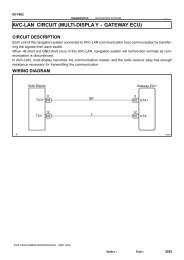
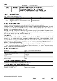
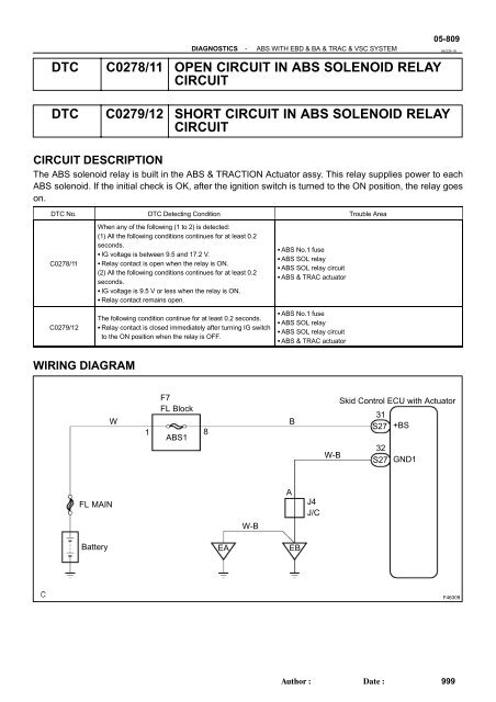
DIAGNOSTICS-ABS WITH EBD & BA & TRAC & VSC SYSTEMDTC C0278/<strong>11</strong> OPEN CIRCUIT IN ABS SOLENOID RELAYCIRCUIT05-80905CD5-19DTC C0279/12 SHORT CIRCUIT IN ABS SOLENOID RELAYCIRCUITCIRCUIT DESCRIPTIONThe ABS <strong>solenoid</strong> <strong>relay</strong> is built <strong>in</strong> the ABS & TRACTION Actuator assy. This <strong>relay</strong> supplies power to eachABS <strong>solenoid</strong>. If the <strong>in</strong>itial check is OK, after the ignition switch is turned to the ON position, the <strong>relay</strong> goeson.DTC No. DTC Detect<strong>in</strong>g Condition Trouble AreaC0278/<strong>11</strong>C0279/12When any of the follow<strong>in</strong>g (1 to 2) is detected:(1) All the follow<strong>in</strong>g conditions cont<strong>in</strong>ues for at least 0.2seconds. IG voltage is between 9.5 and 17.2 V. Relay contact is <strong>open</strong> when the <strong>relay</strong> is ON.(2) All the follow<strong>in</strong>g conditions cont<strong>in</strong>ues for at least 0.2seconds. IG voltage is 9.5 V or less when the <strong>relay</strong> is ON. Relay contact rema<strong>in</strong>s <strong>open</strong>.The follow<strong>in</strong>g condition cont<strong>in</strong>ue for at least 0.2 seconds. Relay contact is closed immediately after turn<strong>in</strong>g IG switchto the ON position when the <strong>relay</strong> is OFF. ABS No.1 fuse ABS SOL <strong>relay</strong> ABS SOL <strong>relay</strong> <strong>circuit</strong> ABS & TRAC actuator ABS No.1 fuse ABS SOL <strong>relay</strong> ABS SOL <strong>relay</strong> <strong>circuit</strong> ABS & TRAC actuatorWIRING DIAGRAMWF7FL Block1 8ABS1BSkid Control ECU with Actuator31S27 +BS32W-BS27 GND1FL MAINAJ4J/CW-BBattery EA EBF46309Author:Date:999
05-810DIAGNOSTICSINSPECTION PROCEDURE1 INSPECT FUSE(ABS1 FUSE)-ABS WITH EBD & BA & TRAC & VSC SYSTEMFL BLOCK(a)(b)Remove ABS1 fuse from the FL BLOCK.Check cont<strong>in</strong>uity of ABS1 fuse.Standard:ABS No.2 fuseBelow 1 Ω (Cont<strong>in</strong>uity)ABS1F40458NGCHECK FOR SHORT IN ALL HARNESS ANDCONNECTOR CONNECTED TO FUSE ANDREPLACE FUSEOK2 INSPECT SKID CONTROL ECU CONNECTOR(+BS TERMINAL VOLTAGE)Skid Control ECU S27(harness side connector)GND1+BSOKG24767(a)(b)(c)Disconnect the skid control ECU connector.Turn the ignition switch to the ON position.Measure the voltage accord<strong>in</strong>g to the value(s) <strong>in</strong> the tablebelow.Standard:Tester ConnectionSpecified ConditionS27-31 (+BS) - S27-32 (GND1) 10 to 14 VNG Go to step 43 RECONFIRM DTC(a) Clear the DTCs (see page 05-765 ).(b) Turn the ignition switch to the ON position.(c) Are the same DTCs recorded?NOTICE:When replac<strong>in</strong>g ABS & TRACTION ACTUATOR ASSY, perform zero po<strong>in</strong>t calibration(see page 05-765 ).NO PROCEED TO NEXT CIRCUIT INSPECTIONSHOWN IN PROBLEM SYMPTOMS TABLE(SEE PAGE 05-786 )YESREPLACE ABS & TRACTION ACTUATOR ASSY (SEE PAGE 32-37 )Author:Date:1000