On the Design and Test of a Low Noise Propeller - CAFE Foundation
On the Design and Test of a Low Noise Propeller - CAFE Foundation
On the Design and Test of a Low Noise Propeller - CAFE Foundation

Create successful ePaper yourself
Turn your PDF publications into a flip-book with our unique Google optimized e-Paper software.
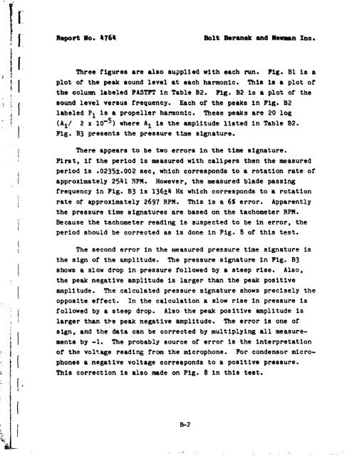
Report No, 4764Bolt Berurek <strong>and</strong> Wenun Ino,Three figures are also su?plied with each run. Fig, B1 is aplot <strong>of</strong> <strong>the</strong> peak sound level at each harmonic. This 18 a plot <strong>of</strong><strong>the</strong> column labeled FASTFT in Table 82. Fig. 82 is a plot <strong>of</strong> <strong>the</strong>aound level versus frequency, Each <strong>of</strong> <strong>the</strong> peaks in Fig. B2labeled P1 is a propeller harmonic. These peaks are 20 logA 2 x log5) where Ai is <strong>the</strong> amplitude listed in Table B2.Fig. 83 presents <strong>the</strong> pressure time signature.There appears to be two errors in <strong>the</strong> time signature.First, if <strong>the</strong> period is measured with calipers <strong>the</strong>n <strong>the</strong> measuredperiod is .0235f.002 aec, which corresponds to a rotation rate <strong>of</strong>approximately 254 1 RPM. However, <strong>the</strong> measured blade passingfrequency in Fig. B3 is 13624 Hz which corresponds to a rotationrate <strong>of</strong> approximately 2697 RPM, This is a 6% error. Apparently<strong>the</strong> pressure time signatures are based on <strong>the</strong> tachometer RPM.Because <strong>the</strong> tachometer reading is saspected to be in error, <strong>the</strong>period should be corrected as is done in Fig. 8 <strong>of</strong> this test.The second error in <strong>the</strong> nteasured pressure time signature is<strong>the</strong> sign <strong>of</strong> <strong>the</strong> amplitude. The pressure signature in Fig. 83shows a slow drop in pressure followed by a steep rise. Also,<strong>the</strong> peak negative amplitude is larger than <strong>the</strong> peak positiveamplitude. The calculated pressure signature shows precisely <strong>the</strong>opposite effect. In <strong>the</strong> calculation a slow rise in pressure isfollowed by a steep drop. Also <strong>the</strong> peak positive emplitude islarger than tbe peak negative amplitude. The error is one <strong>of</strong>sign, <strong>and</strong> <strong>the</strong> data can be corrected by multiplying all measurementsby -1. The probably source <strong>of</strong> error is <strong>the</strong> interpretation<strong>of</strong> <strong>the</strong> voltage reading from <strong>the</strong> microphone. For condensor microphonesa negative voltage corresponds to a po8itive pressure.This correction 1s also made on Fig. 8 in this test.