Mercury Instruments Turbo Corrector - Sensus
Mercury Instruments Turbo Corrector - Sensus
Mercury Instruments Turbo Corrector - Sensus
- No tags were found...

Create successful ePaper yourself
Turn your PDF publications into a flip-book with our unique Google optimized e-Paper software.
<strong>Turbo</strong> <strong>Corrector</strong><strong>Turbo</strong> <strong>Corrector</strong> (TOC)Supplement to:Mini-AT Operator’s GuideV 3.01June 2008P 513.272.11113940 Virginia Avenue, Cincinnati, OH 45227 USAF 513.272.0211 www.mercuryinstruments.com www.rmg.comPage 1
<strong>Turbo</strong> <strong>Corrector</strong>COPYRIGHT NOTICE<strong>Turbo</strong> <strong>Corrector</strong> (TOC) Operator’s Guide(Supplement for Mini-AT Operator’s Guide)COPYRIGHT © 2008 by <strong>Mercury</strong> <strong>Instruments</strong>All Rights Reserved.Page 2
Table of Contents<strong>Turbo</strong> <strong>Corrector</strong>Introduction ....................................................................................................................... 5TIB Connectors/Jumpers (location) ................................................................................... 6Quick Start Guide .............................................................................................................. 7Power Connection .............................................................................................................10Backup Battery ..................................................................................................................10Serial Port Connection....................................................................................................... 11Drawing, Connections for Mini-AT TOC with Slot Sensors ................................................12Drawing, Connections for Mini-AT TOC with Blade Tip Sensors ....................................... 13Solar Power Option ........................................................................................................... 14Drawing, Solar Connections for Mini-AT TOC with Slot Sensors ...................................... 15TIB Operation ....................................................................................................................16Sensor Input Connection .................................................................................................. 18Pulse Outputs ....................................................................................................................19Alarms ............................................................................................................................... 204-20 milliamp output ..........................................................................................................21<strong>Turbo</strong> Frequency Board .................................................................................................... 22Live Graphing ....................................................................................................................24AAT Simulator ................................................................................................................... 26AAT Linearization............................................................................................................... 28Low Frequency Cut-Off...................................................................................................... 29Upgrading TIB Firmware.................................................................................................... 30TOC Item Codes ............................................................................................................... 37Drawing, TOC Mini-AT Assembly Drawing......................................................................... 46Drawing, TOC Mini-AT Parts Layout, No Options...............................................................48Drawing, TOC Mini-AT w/ Optional TFB & Messenger Modem.......................................... 50Drawing, TOC Mini-AT w/ Optional TFB & PT Board..........................................................52Drawing, TOC Mini-AT w/ Optional TFB, Messenger Modem & PT Board.........................54Drawing, TOC 800 Parts Layout.........................................................................................56Drawing, TOC 800 Parts List........................................... ..................................................57Drawing, TOC 800 Simplified Wiring Diagram................................................................... 58Drawing, TOC 800 2nd Pressure....................................................................................... 59Drawing, TOC 800 Standard Switches............................................................................... 60Drawing, TOC 800 Uncorrected Switch..............................................................................61Drawing, TOC 800 Messenger Modem Option.................................................................. 62Drawing, TOC 800 Protocol Translator (PT) Board Option................................................ 63Drawing, TOC 800 4-20 mA Board Option......................................................................... 64Drawing, TOC 800 <strong>Turbo</strong> Frequency Board (TFB) Option................................................. 65Drawing, TOC 800 Single Pulse Alarm (SPA) Board Option.............................................. 66Drawing, Installation for Div. 1 Hazardous Locations ........................................................ 68Drawing, Installation for Div. 2 Hazardous Locations ........................................................ 69Drawing, Wiring AAT with Barrier ...................................................................................... 70Page 3
<strong>Turbo</strong> <strong>Corrector</strong>Revision List1.00 Initial Release May 20021.01 Modified: Various minor changes June 20022.00 Added: Live Graphing p24Parts Lists p41-51Modified: Firmware Upgrade Procedure p27Connection Drawings p11-144-20mA Outputp21Moved: Alarms p19TIB Diagram p6 October 20033.00 Modified: Various major changes that include: February 2008- New layout for the TOC-800- Assembly drawings for the TOC-800- Redesign of input switch assembly- New assembly drawings for TOC (Mini-AT Case)- Info on new AAT Linearization feature- Info on new Low Frequency Cut-off feature- Updates to the Connection Drawings on Pg 12 & 133.01 Modified -Revised cover page July 2008Page 4
<strong>Turbo</strong> <strong>Corrector</strong>IntroductionThe <strong>Turbo</strong> <strong>Corrector</strong> is a full featured Mini-AT Electronic Volume <strong>Corrector</strong> with an internalinterface board called the Turbine Interface Board (TIB). The TIB accepts high-frequencymain and sense rotor signals from the <strong>Sensus</strong> Auto-Adjust <strong>Turbo</strong>-Meter TM (AAT), and calculatesthe adjusted volume based on the <strong>Sensus</strong> AAT algorithms. The TIB transmits lowfrequencyadjusted and unadjusted volume pulses to the Mini-AT board. Depending on thesetting of item 182, pressure, temperature, and supercompressibility correction is applied toeither the Adjusted Uncorrected Volume, the Unadjusted Uncorrected Volume, or the MechanicalUncorrected Volume (from the input reed switches) After each AAT calculationcycle (usually 25,000 main rotor pulses), the TIB initiates a serial communications sessionwith the Mini-AT board to synchronize the values of mirrored item codes that coexist in bothcircuit boards.With newer firmware (2.20 and higher) and newer MasterLink (3.60 and higher),The TIB is also capable of producing separate outputs for the following parameters:- Low-frequency Adjusted Volume pulses (either 100 of 1,000 CF per pulse)- Normal Alarm (Form-A, State-change)- Abnormal Alarm (Form-A, State-change)- Auxiliary Alarm, normally Pulsing Gas (Form-A, State-change)- Buffered main rotor pulses- Buffered sense rotor pulses- 4-20 milliamp (analog) output for either Instantaneous Delta-A or Adjusted Vol Flow Rate.When the optional <strong>Turbo</strong> Frequency Board (TFB) is installed:- High-frequency Adjusted Volume pulses, which can be used for volume totalization orinstantaneous adjusted volume flow rate (Uncorrected)Since the TOC’s main and sense rotors require constant power, which would deplete theprovided alkaline battery pack in a few days, an external power supply of +8.5 volts DC (+/-0.5 volts) is always required. The external power is usually provided by an AC power supply,solar power supply or thermoelectric charger. The standard alkaline battery packserves as short-term battery backup in case of external power failure. Power supplies andbarriers for hazardous locations (Class 1, Divisions 1 & 2) are available.MasterLink32 software is the primary user-interface to the <strong>Turbo</strong> <strong>Corrector</strong>. MasterLink32provides the means to configure, calibrate, upload and download data. Live graphing andstorage of both rotor frequencies, Delta-A and Adjusted Flow Rate are provided.Page 5
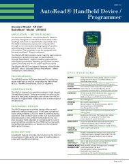
<strong>Turbo</strong> <strong>Corrector</strong>-+ -TB1-+TB2J2J3J4+-+TB3TB4TB5J6JMP1J5TB6J9J7J8+6V +6V - + - +main senseJ10Diagram of the Turbine Input Board(actual size)Connector/Jumper PurposeJ2, J3 Connection for TIB powerJ4Connection for LCD display (not used in TOC)J5RS-232 connection for external case connectorJ6 Firmware upgrade connection #2and connection for <strong>Turbo</strong> Frequency BoardJ7RS-232 connection to instrumentJ8CMOS connection to instrument (not used)J9Connection for AdjVol & UnadjVol pulse output toMini-AT J9J10 Firmware upgrade connection #1JMP1Jumper to select RS-232 (J7) or CMOS (J8) port,usually set on pins 1 & 2 (RS-232)TB1Form-A Adjusted Volume Pulse Output (LF)TB24-to-20 mA output connection (external loop powerrequired)TB3Form-A output connections for Normal, Abnormal andAuxiliary alarmsTB4RS-232 connection for modemTB5Buffered Main and Sense rotor pulse outputTB6Main and Sense rotor pulse input from turbine meterPage 6
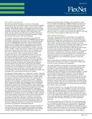
<strong>Turbo</strong> <strong>Corrector</strong>Quick Start GuideThe following steps will guide you to getting the TOC installed and operational.1. Unpack the instrument and verify that there is no shipping damage. Also verify thatnothing is missing from the shipment.2. Open the case door and make sure there are no loose connections or loose hardware.3. Position the <strong>Turbo</strong> <strong>Corrector</strong> on the meter, making sure that the wriggler is alignedproperly. Bolt the <strong>Turbo</strong> <strong>Corrector</strong> to the meter using the mounting bolts and gasket provided.4. Plug the memory battery connector into J26. You may initially see eight 6’s across theLCD while the unit is initializing.5. Install six new D-cell alkaline batteries if using the Alkaline Receptacle Pack. Hang thebattery pack on the screws of the battery hanger plate located inside the door. Install thebattery cover if using a disposable pack. Plug the main battery connector into J8 (J7 willalready be occupied by the TOC power cable).6. Connect the external DC power wires to the field wiring terminal strip of the TOC powercable.7. Connect the sensor cable to the <strong>Turbo</strong>-Meter.MountingScrewsAlkalineBatteryPackTOCPowerCableFieldWiringTerminalStripTIB PowerConnectionsMemoryBatteryJ26 MemoryBatteryConnectorJ7,J8Power CableandMain BatteryConnectorsPage 7
<strong>Turbo</strong> <strong>Corrector</strong>8. Verify that digits appear in the LCD display (usually all zeroes). Scroll through themeter reader list by swiping a mag wand down the right side of the display window to verifythe instrument is operating.Mag Wand(Start at top of label andstroke downward to bottomright corner)Numeric Display9. Connect a standard serial cable from the TOC serial connector to a computer serialport.Mini-ATWarning: Connections to the RS-232 port arepermitted only in nonhazardous locationsM E R C U R YCORRECTED VOLUMELaptop ComputerMETER READ LIST:RS-232 PortSerial Port(i.e.COM1, COM2,)TURBO CORRECTORPressureConnectionI/O CableP/N 40-162910. Run MasterLink32 software and use the “Set Instr. Date/Time via Computer” selectionin the Instrument Menu to set the date and time in the instrument. (Com Port and baudrate may need to be set for the Computer Serial Port. Default baud rate is 9600.)11. Use MasterLink32 to verify that company and site specific items are set properly,especially item 98 (Meter Index Code), and items 863-868.12. Using MasterLink32, run the Live Turbine Graph from the Graphs menu to determine ifthe meter is operating correctly, i.e. rotor frequencies, Delta-A and flow rate.13. Use the “Disconnect Link” function in the Instrument menu to return the <strong>Turbo</strong> <strong>Corrector</strong>back to corrector mode. Remove the I/O cable from the side of the instrument.Page 8
<strong>Turbo</strong> <strong>Corrector</strong>14. Verify the Test Hand rotates in the counter-clockwise direction. If not, remove theblack mechanical index assembly and shift the lower bevel gear to the upper position forCCW meter rotation.Bevel Gear UP for CCW15. Connect the Pressure line to the 1/4" NPT fitting at the side of the instrument.Mini-AT(front view)1/4” NPTfittingPressureLine16. Insert the slip-along fitting into the thermowell, and place the temperature probe intothe slip-along fitting, sliding the probe down until it nearly bottoms out in the thermowellbefore tightening the slip-along nutTemperatureProbeSlip-AlongThermowellFitting17. At this point the instrument should be ready for operation.Page 9
<strong>Turbo</strong> <strong>Corrector</strong>Power ConnectionThe <strong>Turbo</strong> <strong>Corrector</strong> requires 8.5 VDC (+/- 0.5 VDC) from an external source to operate.The standard external source is an AC-to-DC power supply (Div. 1 locations require barriers)with an alkaline battery as backup power. Alternatively, solar power is available, (locationdependent).Note: Damage to the internal Power Distribution Cable will result if external powerexceeds 9.0VDC.When using the standard power supply, the output is connected to the <strong>Turbo</strong> <strong>Corrector</strong>power cable mounted to the left side of the case using the provided terminal strip. The<strong>Turbo</strong> <strong>Corrector</strong> power cable should already have one connection plugged into J7 of theMini-AT main board and the other connection plugged into J2 of the TIB. The alkalinebattery pack plugs into J8 of the Mini-AT board.BatteryTOCPowerDistributionPower ComponentsBattery BackupThe <strong>Turbo</strong> <strong>Corrector</strong> with DC power supply has the option of two battery backup strategies;a short term backup strategy and a long term backup strategy. The short-term strategy(using power cable 40-2809-1) will allow the Mini-AT, TIB, and sensors to remain poweredfor approximately 48 hours. The long-term strategy (using power cable 40-2809-2) willpower the Mini-AT for approximately 3 years. In the long term strategy, the TIB and sensorswill not be powered by the backup battery.The standard configuration for the <strong>Turbo</strong> <strong>Corrector</strong> is the short-term strategy. The longterm configuration is available as an option.Note: It is highly recommended that an Uninterruptible Power Supply (UPS) be used inconjunction with the DC power supply in the short-term configuration to compensate forpossible power failures.Page 10TerminalStrip
<strong>Turbo</strong> <strong>Corrector</strong>Serial ConnectionThe TIB has three serial port connections:- one to connect the TIB to the Mini-AT board to allow internal communications to the Mini-AT board (at J7)- one to connect the TIB to the case connector for a local serial connection (at J5)- one to connect the TIB to remote communications device, modem, radio, etc. (at TB4).Normal serial communications to the Mini-AT are routed through the TIB at J5.MasterLink32 can communicate with either the Mini-AT or TIB depending upon which isselected in the MasterLink32 establish link dialogue box. Item 272 in the Mini-AT board(TB2) and item 856 in the TIB (J7) must be set to the same baud rate, which defaults to9600 for both. Also, the settings at items 857 (External Port Baud Rate (J5), default 9600)and 858 (Modem Port Baud Rate (TB4), default 2400) must match the host baud rate forthe device being used.See the drawings on the next two pages more details on various cable connections.Modem PortConnection TB4(baud rate settingat item 858)Mini-ATserial portto TIB portConnection TB2(baud rate settingat item 272)External CaseConnector PortConnection J5(baud rate settingat item 857)TIB port toMini-AT portConnection J7(baud rate settingat item 856)External CaseConnectorSerial Port ConnectionsPage 11
<strong>Turbo</strong> <strong>Corrector</strong>Page 12TOC w/ Slot Sensors Connection Drawing
<strong>Turbo</strong> <strong>Corrector</strong>TOC w/ Slot Sensors Connection DrawingPage 13
<strong>Turbo</strong> <strong>Corrector</strong>Solar Power OptionSolar power consists of the solar panel, re-chargeable battery, solar charger, and voltageregulator. Power from the solar panel is cabled into the case to the solar charger. Thesolar charger prevents over-charging of the battery while providing power to the battery andthe <strong>Turbo</strong> <strong>Corrector</strong>. Installation location and panel size must be taken into considerationto determine if the solar panel will generate enough power for the <strong>Turbo</strong> <strong>Corrector</strong>. Severalpanel and battery configurations are available.Short-term is the only power back-up strategy available for the solar power option. Ifpower from the solar panel is interrupted, a fully-charged battery can generally last 3.5 and15 days, depending upon the size of the battery in the solar power system.SolarChargingUnitBatteryShelfVoltageRegulatorSolar Power Connection (800 Series Case)Page 14
<strong>Turbo</strong> <strong>Corrector</strong>TOC Solar Power Connection Drawingwith Slot SensorsPage 15
<strong>Turbo</strong> <strong>Corrector</strong>Turbine Interface Board OperationThe basic purpose of the Turbine Interface Board (TIB) is to accept high-frequency pulsesfrom the main and sense rotor sensors of the Auto-Adjust <strong>Turbo</strong>-Meter (AAT), compute the<strong>Sensus</strong> algorithms, and output low-frequency adjusted and unadjusted volume pulses to J9of the Mini-AT main board. The value of each of the low-frequency pulses is determined bythe setting at item 098 (Meter Index Code). The TIB will check the main and sense rotorfrequency every 1 second and send Adjusted and Unadjusted volume pulses when thevolume accumulated has reached the value at item 098.The Adjusted Volume (V A) and Unadjusted Volume (V U) are calculated as follows:V A=P MP- SK MK SV U=P MK MOWhere: V A= Adjusted Volume V U= Unadjusted VolumeP M= Main Rotor Pulses P S= Sense Rotor PulsesK M= Main Rotor Factor K S= Sense Rotor FactorK MO= Mechanical Output FactorThe calculated values of Adjusted and Unadjusted volume should be very close to eachother. However, flow conditions, mechanical problems and electrical problems can cause adeviation between the two. This deviation is calculated by the TIB as a percentage. Thispercent deviation from factory calibration is known as Delta A (DA). The value of Delta A isupdated every Auto-Adjust cycle. The Auto-Adjust cycle is defined as every 25,000 mainrotor pulses or every 8.5 minutes, whichever occurs first.Delta A is calculated as follows: ∆A =P MK M100- 1P SK S- A barWhere:DA = % Deviation from Factory CalibrationA bar= Average Relative Adjustment at factory calibrationP M= Main Rotor PulsesP S= Sense Rotor PulsesK M= Main Rotor FactorK S= Sense Rotor FacPage 16
Sensor Cable Connections<strong>Turbo</strong> <strong>Corrector</strong>Original ConfigurationIn order to allow the instrument to function in <strong>Turbo</strong> <strong>Corrector</strong> mode (i.e. TIB periodicallyupdating Mini-AT items), item 855 must be set to <strong>Turbo</strong> <strong>Corrector</strong> Mode. By enabling thismode, and with the default selection of item 182 (Input Volume to <strong>Corrector</strong>) set to TIB AdjVol (SW3), volume correction is made from the adjusted volume pulses sent from the TIBto Mini-AT board at J9. Also, the numerous Serial Log Triggers generated by the TIB’sserial connection are automatically disabled to keep Audit Trail memory from filling up withserial access logs from the TIB.Input Parameters from the Auto-Adjust <strong>Turbo</strong>-MeterIt is critical that the following <strong>Turbo</strong> <strong>Corrector</strong> items are properly configured with parametersfrom the Auto-Adjust <strong>Turbo</strong>-Meter. Without properly configuring these items, the <strong>Turbo</strong><strong>Corrector</strong> will produce incorrect volume information.The items are:863 Meter Serial Number864 Turbine Meter Size865 Km Meter Factor - pulses per cubic foot of the main rotor866 Ks Meter Factor - pulses per cubic foot of the sense rotor867 ABar Meter Factor - average amount of adjustment from factory calibration868 Kmo Meter Factor - pulses per cubic foot of the mechanical output (unadjusted)The values for these items are found on the <strong>Turbo</strong>-Meter’s serial plate with the exception ofKMO Meter Factor, which can be found on the factory calibration data sheet. Note: It isvery important that item 868 (Kmo Meter Factor) is configured with the KMO value.If not, the TIB will compute inaccurate values for Unadjusted Volume.Sensor Input ConnectionThe main and sense rotor signals are to be connected from the <strong>Turbo</strong>-Meter’s slot sensorsto TB6 of the TIB board using the supplied 4-foot Sensor Cable (p/n: 40-2833-1). An optional25 foot cable is also available for remote mounting locations (p/n: 40-2833-25). If the<strong>Turbo</strong>-Meter incorporates blade-tip sensors, a different input cable is require since theconnector requires six pins instead of the normal five pins. For blade-tip meters, use inputcable p/n 40-3033.Sensor InputCableSense Rotor +(white)Sense Rotor -(orange)Main Rotor +(red)Main Rotor -(black)Shield wire(clear)Page 18
<strong>Turbo</strong> <strong>Corrector</strong>AlarmsIn addition to the standard Mini-AT Alarms (listed in the Mini-AT Operator’s Guide) there arefour alarms for the TOC. These alarms exist in the Turbine Interface Board (TIB) and aretransferred to the Mini-AT on the AAT calculation cycle, where they are date & time-stampedinto the Alarm Logger.Alarm Description Item# Alarm Code Dead Band Item# Alarm Limit Item#Pulsing Gas Alarm 874 .E.8.7.4. Fixed in Firmware Fixed in FirmwareTIB Internal Fault 875 .E.8.7.5. None NoneNormal Alarm 877 .E.8.7.7. 879 872Abnormal Alarm 878 .E.8.7.8. 880 873Alarm OutputsThe <strong>Turbo</strong> <strong>Corrector</strong> will generate a Form-A output on every new alarm. The alarm outputsare available on TB3 of the Turbine Interface Board. There are three outputs available: theNormal alarm, Abnormal alarm and Aux out. The Aux out channel is used for the low battery,internal fault and pulsing gas alarms. At the occurrence of any alarm, the appropriate outputwill latch into the ON or closed state and remain in that state until cleared by RBX, software orfirmware.Initial Recommended Alarm ConfigurationOperating ConditionsAlarm LimitsNormal(Item 872)Abnormal(Item 873)Normal(Item 879)Dead BandAbnormal(Item 880)Meter flow rate 50% to 100% of ratedcapacity. Pressures over 275 psi.Meter flow rate 20% to 100% of ratedcapacity. Pressures over 275 psi.Meter flow rate 20% to 100% of ratedcapacity. Pressure range 50 to 275 psi.Meter flow rate 5% to 100% of ratedcapacity. Pressures less than 50 psi.+/- 0.5% +/- 2.0% 0.05% 0.2%+/- 0.75% +/- 3.0% 0.075% 0.3%+/- 1.0% +/- 3.0% 0.1% 0.3%+/- 1.25% +/- 4.0% 0.125% 0.4%+/- 1.5% +/- 4.0% 0.15% 0.4%+/- 1.75% +/- 4.0% 0.175% 0.4%+/- 2.0% +/- 5.0% 0.2% 0.5%+/- 2.5% +/- 5.0% 0.25% 0.5%Use these values if you can’t decide onany of the above+/- 2.0% +/- 5.0% 0.2% 0.5%TOC AlarmsPage 20
<strong>Turbo</strong> <strong>Corrector</strong>4-20 milliamp outputIn addition to the pulse outputs, the <strong>Turbo</strong> <strong>Corrector</strong> has a single 4-20 milliamp output channelavailable at TB2. The TIB updates the 4-20mA output every 5 seconds. The channel isconfigurable to output either Delta-A or Adj Vol Flowrate. The selection is made at item 871(TIB 4-20 Out Config). The limits for Delta-A output are fixed at -5% (4ma) and +5% (20ma).The Adj Vol flow rate limits are user selected at items 884 (20ma) and 885 (4ma). The outputrequires loop power, and must have a minimum of 9VDC across the + and - terminals underany load condition. 24 volts DC loop power is typical.The 4-20 milliamp output function can be verified by changing the selection at item 871 and thendisconnect the serial link. Depending on the setting, the 4-20 mA output can provide a constant4, 12 or 20mA signal for verification or calibration purposes. Note, disconnect link after eachchange at allow the configuration to take affect. After verification, Item 871 should be set backto either Delta-A or Adj Vol Flowrate for the output to function normally.TB1 AdjustedVolume outputTB2 4-20maoutputTB3 AlarmoutputsTB5 Main andSense rotorbuffered outputs(high frequency)Pulse and 4-20mA Output Connection Locations24VDC -Supply +-+4-20mAReceiver(w/o powered loop)-+4-20mAReceiver(w/ powered loop)TIBTIB+ -4-20output4-20mA Output Connections+ -4-20outputPage 21
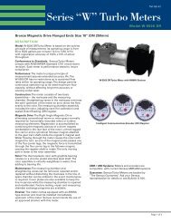
<strong>Turbo</strong> <strong>Corrector</strong><strong>Turbo</strong> Frequency Board (TFB)The <strong>Turbo</strong> Frequency Board (TFB) is an optional accessory that outputs a proportionalsignal for Adjusted Volume flow, providing up to 1,000 pulses per second at the specified100% flow rate of any Auto-Adjust <strong>Turbo</strong>-Meter. The high frequency output is accuratelyscaled so that each pulse can be accumulated for remote volume readings (either Ft 3 orm 3 ) or may be used as a flow rate signal. A maximum frequency parameter (Item 889)permits the user to select the desired number of pulses that will correspond to the maximumrated flow of the meter. Choices for maximum frequency are 50, 100, 200, 500 or1,000 hertz. The turbine meter size (Item 864) and the meter index units (Item 098) mustbe properly configured to obtain the proper frequency from the TFB.The <strong>Turbo</strong> Frequency Board plugs into the TIB at connector J6 and is secured by two mountingscrews. The TFB receives its power and input signal through J6 while providing the outputfrequency at TB1 on the <strong>Turbo</strong> Frequency Board. The frequency output must be wetted by a3-15 volts DC receiver for proper operation.The TFB includes a red LED (D1) that blinks at a slow rate (once per second) when power isfirst applied and while waiting for a valid packet of data. The faster rate (7 times per second)indicates that a valid packets have been received and an output frequency has been transmittedto the opto-coupler. During normal operation, the LED will always blink at the faster rate.LED (D1)connectionto TIB J6(reverse side ofboard)MountingpointsFrequency outconnection (TB1)<strong>Turbo</strong> Frequency Board (installed)Page 22
<strong>Turbo</strong> <strong>Corrector</strong><strong>Turbo</strong> Frequency Board Pulse FactorsMeter(English)50 Hz.Output Frequency @ Max. Flow Rate100 Hz. 200 Hz. 500 Hz.1000 Hz.ModelSize(in.)BladeAnglePulsesper Ft 3Ft 3 perpulsePulsesper Ft 3Ft 3 perpulsePulsesper Ft 3Ft 3 perpulsePulsesper Ft 3Ft 3 perpulsePulsesper Ft 3Ft 3 perpulseAAT-18AAT-30/35AAT-60AAT-140AAT-27AAT-57AAT-90AAT-230Model4681246812Meter(Metric)45 O45 O45 O45 O30 O30 O30 O30 OSize Blade(mm) Angle10531.26320.8Pulsesper m 30.1000000.2000000.3333330.8333330.1666670.3333330.5000001.25000050 Hz.m 3 perpulse201062.412641.6Pulsesper m 30.0500000.1000000.1666670.4166670.0833330.1666670.2500000.625000Output Frequency @ Max. Flow Rate100 Hz. 200 Hz. 500 Hz.m 3 perpulse4020124.8241283.2Pulsesper m 30.0250000.0500000.0833330.2083330.0416670.0833330.1250000.312500m 3 perpulse1005030126030208Pulsesper m 30.0100000.0200000.0333330.0833330.0166670.0333330.0500000.125000m 3 perpulse2001006024120604016Pulsesper m 30.0050000.0100000.0166670.0416670.0083330.0166670.0250000.0625001000 Hz.m 3 perpulseAAT-18 100AAT-30/35 150AAT-60 200AAT-140 300AAT-27 100AAT-57 150AAT-90 200AAT-230 30045 O45 O45 O45 O30 O30 O30 O30 O3501751054521010570280.0028570.0057140.0095240.0222220.0047620.0095240.0142860.03571470035021090420210140560.0014290.0028570.0047620.01111110.0023810.0047620.0071430.01785714007004201808404202801120.0007140.0014290.0023810.0055560.0011900.0023810.0035710.008929350017501050450210010507002800.0002860.0005710.0009520.0022220.0004760.0009520.0014290.0035717000350021009004200210014005600.0001430.0002860.0004760.0011110.0002380.0004760.0007140.001786Table 3Volume Per Pulse for various meter sizes and FrequenciesPage 23
<strong>Turbo</strong> <strong>Corrector</strong>Live Graphing (Turbine Related Items)The <strong>Turbo</strong> <strong>Corrector</strong>, via MasterLink has the capability to graph turbine related items. Thegraphable items are Main Rotor Frequency, Sense Rotor Frequency, Instantaneous DeltaA, Adjusted Volume Flow Rate and High Frequency Adjusted Volume. These items can begraphed one at a time, or up to a maximum of four. Each item has a configurable scale,line color and line style. The graph is ‘live’ with a configurable update interval and viewinginterval. The figure below shows a sample graph with four items on the graph. Notice thatthe last updated value of each item is shown as a numeric value in a display box at thebottom of the graph.The graph window also has a tool bar at the top that is used to customize the graph. Thetoolbar can be used to change background colors, show gridlines, zoom in or out and showthe graph in 3D. The Graph Setup button at the bottom of the graph will pull up the GraphConfiguration screen, as outlined on the next page. Clicking the Reset Style button willreset the configuration to default. Clicking the Close button will exit the Live Graph mode.Live Graph DisplayPage 24
<strong>Turbo</strong> <strong>Corrector</strong>Live Graph ConfigurationThe live graph can be setup using the Graph Configuration. The Y Axis Item column isused to choose which items are to be graphed. Clicking on the drop down arrow will causea list of items to appear. Simply select the desired item from the list. If only one or twoitems are to be graphed, select those items for the first one or two and change the remainingitems to None. The Y Minimum and Y Maximum columns are use to select a range ofvalues to scale on the graph. The Color and Line Style columns are used to configure thetype of line to be displayed on the graph.Other graphing options are set in the lower Options portion of the Setup screen. TheReading Interval is used to set up how often the software interrogates the <strong>Turbo</strong> instrumentfor the information that is being graphed. This can be set from 1 to 30 seconds. The X-axis Width configures how much of a time interval to show on the graph. The default is 30seconds. There are also two check boxes. When checked, the Show ToolBar displays thetoolbar at the top of the graph window. The second, Show Data Points on Lines displays adot on the graphing lines for each retrieved data value.Live Graph ConfigurationPage 25
<strong>Turbo</strong> <strong>Corrector</strong>AAT SimulatorA compact, portable device is available for testing the electronic functions of a <strong>Turbo</strong> <strong>Corrector</strong>.The AAT Simulator (p/n 40-2835) will simulate main and sense rotor signals fromthe AAT. Two rocker switches are provided, a two position switch to change the main rotorfrequency, and a three position switch for changing the sense rotor frequency, which will inturn, affect the Delta-A value calculations. The simulator is connected to the Instrumentthrough the sensor input cable and is powered by a standard, external <strong>Mercury</strong> batterypack.Connection tostandard<strong>Mercury</strong>battery packConnection toSensor Input CablePage 26
<strong>Turbo</strong> <strong>Corrector</strong>Turbine Datato be enteredinto TIBSense RotorSwitchMain RotorSwitchPage 27
<strong>Turbo</strong> <strong>Corrector</strong>AAT Linearization Setup FormLow Frequency Cut-Off (Main Rotor)Starting with firmware version 2.20, item 406 (AAT Low Flow Cut-Off Hz) was added toallow the user to specify a low flow cut-off for the main rotor only. The cut-off is expressedin Hertz as an integer value from 1 to 40, and defaults to the previously hard-coded valueof 3 Hz. Main rotor volume that comes into the TIB at a frequency at or above the 406value is accepted, but volume that comes in at a frequency below 406 is not registered.This feature is to help reduce or eliminate the processing of no-net resonant flows, such asmain rotor oscillation during no flow conditions.Page 29
<strong>Turbo</strong> <strong>Corrector</strong>Upgrading TIB firmware1. Items RequiredPC with Windows 95/98 OS (or higher)Firmware Upgrade Manager software (FWUM) version 2.1101 or later Install FirmwareUpgrade Manager software, which is usually provided on the MasterLink32 CDunder the “Bonus Software” folder. NOTE: Always install the program “<strong>Mercury</strong>Calculator” prior to Firmware Upgrade Manager when working on a Windows XP machine.TIB Firmware file for Controller 103 (U15) (TIBxxxxx.tbx) and TIB Firmware file forController 8515 (U9) (T8Bxxxxx.t8x<strong>Mercury</strong> Programming Adapter (MPA) p/n 40-2620, with version 1.1002 firmware (orhigher).RS-232 serial I/O cable, p/n 40-1629TIB board, p/n 40-2708 (may be part of a TOC or TOM assembly)TOC Power cable p/n 40-2809-1 (with battery or DC power connected) or TOM Powercable p/n 40-2812 (with battery or DC power connected)Page 30
<strong>Turbo</strong> <strong>Corrector</strong>2. Programming the TIB:2.1 Programming both Microcontrollers (103 & 8515) with <strong>Mercury</strong> MPA1. Connect MPA to PC serial port via the 40-1629 cable.2. Connect MPA ribbon cable (10-pin header conn) to TIB (J10) port (red wire topin #1).PC runningFWUMversion2.11013. Start <strong>Mercury</strong> Firmware Upgrade Manger and select “TIB“ from icon toolbar.A Dialog box appears to explain the sequence of connecting the MPA ribboncable during programming.Page 31
<strong>Turbo</strong> <strong>Corrector</strong>Note: The TIB requires the firmware in the 103 Microcontroller (U15) to be erased beforethe firmware in the 8515 Microcontroller (U9) can be programmed. For this reason, theMPA is to be plugged into J10 first to erase the 103 Microcontroller (U15) firmware beforechanging to J6 for programming the 8515 Microcontroller (U9) firmware.4. Send … \ tibXXXXX.t8x” file (use file browser if required).5. FWUM erases, the main program, then disconnects from the MPA.Page 32
<strong>Turbo</strong> <strong>Corrector</strong>6. Unplug the MPA from J10 and plug it into J6 so FWUM can upgrade the 8515firmware.Page 33
<strong>Turbo</strong> <strong>Corrector</strong>7. After the 8515 firmware upgrade is complete, unplug the MPA cable for J6 and plugit back into J10. Chose the .8. Select the “tbx“ file from list box and click OK to begin upgrading the main TIBfirmware.Page 34
<strong>Turbo</strong> <strong>Corrector</strong>9. After both TIB processors are upgraded, exit FWUM.Page 35
<strong>Turbo</strong> <strong>Corrector</strong>B L A N K P A G EPage 36
<strong>Turbo</strong> <strong>Corrector</strong>ItemNo. Item Name Description397 Meter Factor Adj Min The minimum, linearized value of adjusted meterfactor that has occurred during the current log interval(defined at item 202). This parameter, along with alllinearization diagnostic items (items 393-398) are helpfulin verifying the performance of the AAT Linearizationfeature, especially when all six items are logged in theexpanded audit trail.Default = 0.0000398 Meter Factor Adj Max The maximum, linearized value of adjusted meterfactor that has occurred during the current log interval(defined at item 202). This parameter, along with alllinearization diagnostic items (items 393-398) are helpfulin verifying the performance of the AAT Linearizationfeature, especially when all six items are logged in theexpanded audit trail.Default = 0.0000406 AAT Low Flow The low-end frequency of the main rotor signal at whichCut-Off Hz.the TIB assumes a value of zero, until exceeded. Thisuser specified parameter is to help reduce or eliminateprocessing of no-net resonant flows, such as main rotoroscillation during no flow conditions.Range: 1 - 40 Hz.Default = 3 Hz.850 Adjusted Volume Totalized Adjusted Uncorrected Volume. This value isscaled to volume units selected at Item 092 and to thenumber of digits defined by Item 097.Default = 00000000851* Hi Res Adjusted Volume Fractional portion of Item Code 850 (Adjusted Volume)displayed in units of ft 3 or m 3 . This item is continuouslyupdated until it reached the value of adjusted volumeunits at Item 092. At that point, item 850 is updated anditem 851 is reset to zero.Default = 0.000000852 UnAdjusted Volume Totalized Unadjusted Uncorrected Volume. This value isscaled to volume units selected at Item 092 and to thenumber of digits defined by Item 097.Default = 00000000Page 38
<strong>Turbo</strong> <strong>Corrector</strong>ItemNo. Item Name Description853 Turbine Adj Flow Rate The current instantaneous rate of flow for Adjusted Volume(850), expressed in the selected Adjusted Volumeunits (ft 3 or m 3 ) per hour. The value is updated every1-second in the TIB and transferred to the Mini-AT boardon every AAT Cycle serial link. When accessed, the unitwill display the most recently computed value.Default = 0.00854 Turbine UnAdj Dial Rate The current instantaneous rate of flow for UnadjustedVolume (852), expressed in the selected UnadjustedVolume units (ft 3 or m 3 ) per hour. The value is updatedevery 1-second in the TIB and transferred to the Mini-ATboard on every AAT Cycle serial link. When accessed,the unit will display the most recently computed value.Default = 0855 Turbine Configuration Item used to determine the configuration of the instrument,A selection of ‘0’ at item 855 is used for standaloneMini-AT and <strong>Turbo</strong> Monitor units. A selection of ‘1’at item 855 is used for <strong>Turbo</strong> <strong>Corrector</strong>s and enablesserial communication between the TIB and Mini-ATmainboards. FYI - Normally, serial communications withthe Mini-AT board passes through the TIB.Select:0 – Turbine Support Off1 – <strong>Turbo</strong> Monitor Mode856* <strong>Corrector</strong> Baud Rate Code (0-7) to select the baud rate at TIB port J7. ThisCodeport is normally used to make a serial link to the Mini-ATin the <strong>Turbo</strong> <strong>Corrector</strong> mode and is generally not used inthe <strong>Turbo</strong> Monitor mode. A communication’s error willoccur if this baud rate does not match the baud rate ofTB2 of the connected Mini-AT board.Select:0 – 9600 Default 4 – 6001 – 4800 5 – 3002 – 2400 6 – 192003 – 1200 7 – 38400Page 39
<strong>Turbo</strong> <strong>Corrector</strong>ItemNo. Item Name Description857* Ext Case Conn Code (0-7) to select the baud rate at TIB port J5. ThisBaud Rate Code port is normally used to make a local serial connection. Acommunication’s error will occur if this baud rate does notmatch the baud rate of the connected external device.Select:0 – 9600 Default 4 – 6001 – 4800 5 – 3002 – 2400 6 – 192003 – 1200 7 – 38400858* Modem Port Code (0-7) to select the baud rate at TIB port TB4. ThisBaud Rate Code port is normally used to make a serial connection to anexternal modem. A communication’s error will occur if thebaud rate does not match the baud rate of the externalmodem (or other serial device).Select:0 – 9600 4 – 6001 – 4800 5 – 3002 – 2400 Default 6 – 192003 – 1200 7 – 38400859 Adj Vol Pulses Waiting Number of Adjusted Volume pulses waiting to be sentfrom J9 of the TIB to J9 of the Mini-AT board.860 UnAdj Vol Pulses Number of Unadjusted Volume pulses waiting to be sentWaitingfrom J9 of the TIB to J9 of the Mini-AT board.861 TIB Serial Number Factory assigned TIB Serial Number.Example: 09901234.x9901234- disregard the leading zerox99xxxxx – 2-digit year of manufacturexxx01234 - 5-digit sequence numberduring the year of manufactureDefault = 00000000.862 TIB Firmware Version This item is used to display the TIB’s operating firmwareversion number. The read-only number is automaticallyinserted when a firmware file is uploaded into FLASHmemory.863 Meter Serial Number Serial number of the turbine meter connected to the TIB.The number must be entered by the user.Default = 00000000Page 40
<strong>Turbo</strong> <strong>Corrector</strong>ItemNo. Item Name Description870 Turbine Sensor Type Selection to indicate the type of sensor used in the connectedAAT meter. Typically, Slot Sensors output approximately500 Hz. at max. capacity, while Blade TipSensors output approximately 1100 to 2100 Hz. at max.capacity.Select:0 – Slot Sensor Default1 – Blade Tip Sensor871 TIB 4-20 Out Config Selection that determines the type of analog signal providedat the 4-20 output port (TB2).Select:0 – Delta-A Default 3 – 12mA (Test)1 – AdjVol Flow Rate 4 – 20mA (Test)2 – 4mA (Test)872 Normal Alarm Limit User selectable limit for Delta-A, entered as a percentageof Abar. When exceeded, produces a “Normal Alarm” atitem 877. The range is ±10%.Default = ±2.0%873 Abnormal Alarm Limit User selectable limit for Delta-A, entered as a percentageof Abar. When exceeded, produces an “Abnormal Alarm”at item 878. The range is ±10%.Default = ±5.0%874 Pulsing Gas Alarm Indicates if pulsing gas is detected by the Delta-A algorithm.If detected, an alarm is indicated at TB3, placingdots on the LCD and “11111111” at Item 874. “00000000”in Item 874 indicates there is no Pulsing Gas Alarm. Thealarm indicators will remain active until manually cleared(by software) or automatically cleared (by RBX in thefirmware).Default = 00000000875 TIB Internal Fault This item indicates if an alarm for the TIB F/W was generated.When the microprocessor detects a TIB F/WFault, an alarm is indicated at TB3, placing dots on theLCD and “11111111” at Item 875. “00000000” at Item875 indicatesthere is no TIB F/W Alarm. The alarmindicators will remain active until manually cleared (bysoftware).Default = 00000000Page 42
<strong>Turbo</strong> <strong>Corrector</strong>ItemNo. Item Name Description876* TIB Alarms Output This item displays “11111111” to indicate that a TIB alarm(874-875, or 877-878) has become active, and that analarm pulse was transmitted out the Alarm Channel.“00000000” at Item 876 indicates there are no activealarms.Default = 00000000877 TIB Normal Alarm This item indicates if Delta-A is outside the normal alarmband, i.e., if the calculation for Item 869 (InstantaneousDelta-A) is a value (+ or -) that exceeds the Normal AlarmLimit (item 872), an alarm is indicated at TB3, placingdots on the LCD and “11111111” at Item 877.“00000000” at Item 877 indicates there is no NormalAlarm. The alarm indicators will remain active untilmanually cleared (by software) or automatically whenRBX (item 165) is enabled.Default = 00000000878 TIB Abnormal Alarm This item indicates if Delta-A is outside the abnormalalarm band, i.e., If the calculation for Item 869 (InstantaneousDelta-A) is a value (+ or -) that exceeds the AbnormalAlarm Limit (item 873), an alarm is indicated at TB3,placing dots on the LCD and “11111111” at Item 878.“00000000” at Item 878 indicates there is no AbnormalAlarm. The alarm indicators will remain active untilmanually cleared (by software) or automatically whenRBX (item 165) is enabled.Default = 00000000879 Normal Alarm A hysteresis band that provides a buffer above or belowDead Bandthe Normal Alarm Limit (Item 872) when Normal Alarmsare automatically cleared by RBX operation. The userspecified value determines the magnitude of the band.The Delta-A value must pass completely through theband before the alarm is reset. The band applies to boththe plus and minus side of the Normal Alarm Limit.Default = 1.0000Page 43
<strong>Turbo</strong> <strong>Corrector</strong>ItemNo. Item Name Description880 Abnormal Alarm A hysteresis band that provides a buffer above or belowDead Bandthe Abnormal Alarm Limit (Item 873) when AbnormalAlarms are automatically cleared by RBX operation. Theuser specified value determines the magnitude of theband. The Delta-A value must pass completely throughthe band before the alarm is reset. The band applies toboth the plus and minus side of the Abnormal AlarmLimit.Default = 1.0000881 Main Rotor Frequency Value of the most recent measurement of main rotorinput frequency, in Hertz (pulses per second).Default = 0.0000882 Sense Rotor Frequency Value of the most recent measurement of sense rotorinput frequency, in Hertz (pulses per second).Default = 0.0000883 Adjusted Volume Pulses Number of Adj Vol output volume pulses waiting to besent out the TIB pulse channel at TB1.Default = 0884 Adj Flow 20mA Value An integer number used to scale the high end of theTIB’s 4-20 mA output signal at TB2. This user selectablevalue determines at what point the Adj Vol flow rate (Item853) is equal to 20 mA.Default = 0.0000885 Adj Flow 4mA Value An integer number used to scale the low end of theTIB’s 4-20 mA output signal at TB2. This user selectablevalue determines at what point the Adj Vol flow rate (Item853) is equal to 4 mA.Default = 0.0000886 Average Delta A The average of all Delta-A calculations obtained duringthe Audit Trail log interval (item 202).Default = 0.0000887 8515 Firmware Version The version number of the TIB’s second operatingfirmware. This read-only number is automaticallyinserted when a firmware file is uploaded into flashmemory.Page 44
<strong>Turbo</strong> <strong>Corrector</strong>ItemNo. Item Name Description888 Incremental Adjusted Same as ADJVOL (item 850), but is initialized (re-zeroed)Volumeat the beginning of every TIME-triggered wake up(item 202). If the instrument is accessed, this item willdisplay the current value for that point in time.889 High Freq Out Max Freq The frequency out of the <strong>Turbo</strong> Frequency Board (atTB1) when the AAT meter is at its designed 100% flowrate. The frequency for this condition is user specified toallow compatibility with most data acquisition systems orRTU devices.Select:0 - 50 Hz. Default1 - 100 Hz.2 - 200 Hz.3 - 500 Hz.4 - 1000 Hz. (Most common choice)890 Counts per Delta-A The number of main rotor pulses that triggers the nextDelta-A calculation. If the specified number of pulses arenot received within 8-1/2 minutes (due to low flow rates),Delta-A is automatically re-calculated based on the 8-1/2minute timeout.Default = 25,000Min. Allowed = 5,000Mini-AT Items mirrored in the TIBThe following Mini-AT items are read by the TIB and the values duplicated in TIB itemshaving the same item code number. Please refer to the Mini-AT Operator’s guide for descriptionsof these items.049 Battery Voltage Low Limit050 Shutdown Voltage092 Uncorrected Volume Units097 Uncorrected Volume Display Resolution098 Meter Index Code165 RBX Alarm Enable170 Protocol Code A171 Timeout Delay 1172 Timeout Delay 2200 Site ID 1201 Site ID 2Page 45
<strong>Turbo</strong> <strong>Corrector</strong>TOC(Mini-AT Case)Assembly DrawingPage 46
<strong>Turbo</strong> <strong>Corrector</strong>Page 47
Page 48<strong>Turbo</strong> <strong>Corrector</strong>
TOC(Mini-AT Case)w/ TFB andMessenger Modem<strong>Turbo</strong> <strong>Corrector</strong>Page 51
Page 52<strong>Turbo</strong> <strong>Corrector</strong>
TOC(Mini-AT Case)w/ TFB andPT Board<strong>Turbo</strong> <strong>Corrector</strong>Page 53
Page 54<strong>Turbo</strong> <strong>Corrector</strong>
TOC(Mini-AT Case)w/ TFB, MessengerModem & PT Board<strong>Turbo</strong> <strong>Corrector</strong>Page 55
Page 56<strong>Turbo</strong> <strong>Corrector</strong>
<strong>Turbo</strong> <strong>Corrector</strong>TOC - 800Parts ListPage 57
<strong>Turbo</strong> <strong>Corrector</strong>TOCCabling DiagramPage 58
<strong>Turbo</strong> <strong>Corrector</strong>TOC - 8002nd Pressure OptionPage 59
<strong>Turbo</strong> <strong>Corrector</strong>TOC - 800Standard SwitchesPage 60
<strong>Turbo</strong> <strong>Corrector</strong>TOC - 800Uncorrected SwitchPage 61
<strong>Turbo</strong> <strong>Corrector</strong>TOC - 800Messenger Modem OptionNOTES:1) Red wire: +DC 2) Wht wire: TxBlk wire: COM Red wire: RxPage 62
<strong>Turbo</strong> <strong>Corrector</strong>TOC - 800PT Board OptionPage 63
<strong>Turbo</strong> <strong>Corrector</strong>TOC - 8004-20 mA Board OptionPage 64
<strong>Turbo</strong> <strong>Corrector</strong>TOC - 800PT Board OptionPage 65
<strong>Turbo</strong> <strong>Corrector</strong>TOC - 800SPA Board OptionPage 66
<strong>Turbo</strong> <strong>Corrector</strong>B L A N K P A G EPage 67
Page 68<strong>Turbo</strong> <strong>Corrector</strong>
<strong>Turbo</strong> <strong>Corrector</strong>Page 69
Page 70<strong>Turbo</strong> <strong>Corrector</strong>