
Create successful ePaper yourself
Turn your PDF publications into a flip-book with our unique Google optimized e-Paper software.
<strong>ORION</strong>-PVersion 03: CL, PB, PS, PL, PPOperation manual
Dear customer,Thank you very much for your confidence and for choosing this <strong>Hotraco</strong> Agri product!<strong>Hotraco</strong> Agri BV and our dealer guarantee you will receive the optimal efficiency from your investment.If you have any questions or if you are in need of support, you can always depend on your <strong>Hotraco</strong> Agridealer. You can also find answers on our website www.hotraco.com on many questions asked regarding theoperation of our products. See therefore the selection key 'online helpdesk' on the website. Furthermore,<strong>Hotraco</strong> Agri BV has the disposal of a 24-hour service organisation, which is ready to help you duringemergency situations. The phone number is +31 77 327 5020 (24 hours a day, 365 days per year).We thank you once again for your choice and look forward with interest to any suggestions regarding ourproducts.With kind regards,C.W.M. BeelenPresident <strong>Hotraco</strong> Holding bvAbout this manualRead this manual carefully before installing and operating the system. Please be aware of the safetyinstructions for which you are warned when starting up the computer.All rights reserved. Reproduction of any part of this manual in any form without express written permissionfrom <strong>Hotraco</strong> Agri BV, is forbidden. The contents of this manual are subject to change without notice.However, <strong>Hotraco</strong> Agri BV cannot give any guarantee for this manual.This edition and the information within, has been put together with the best possible care. However, shouldany errors be detected, <strong>Hotraco</strong> Agri BV would greatly appreciate being informed of them.Copyright © 2010 <strong>Hotraco</strong> Agri BV05-07-10
Table of contentsTable of contents1 Introduction....................................................................................................................................................12 Operation........................................................................................................................................................22.1 The readout ............................................................................................................................................22.2 Retrieving and altering settings ..............................................................................................................32.3 Curves ....................................................................................................................................................42.3.1 Retrieving and altering a curve....................................................................................................42.3.2 Day number.................................................................................................................................52.4 Timer settings.........................................................................................................................................52.5 Remote control .......................................................................................................................................73 Controls (F1) ..................................................................................................................................................83.1 Ventilation control ...................................................................................................................................83.1.1 The Ventilation system ................................................................................................................93.1.2 Day/night set temperature...........................................................................................................93.1.3 Switching off fans ........................................................................................................................93.1.4 Ventilation on basis of m 3 /hour/kg.............................................................................................103.2 Damper control.....................................................................................................................................113.3 Air inlet control......................................................................................................................................123.3.1 Control on basis of the temperature..........................................................................................123.3.2 Control on basis of the negative pressure.................................................................................133.3.3 Control on the basis of the ventilation position (synchronous)..................................................153.4 Winter garden.......................................................................................................................................163.5 Mixing ventilation ..................................................................................................................................173.5.1 ON / OFF contact ......................................................................................................................173.5.2 Proportional control through 0-10V signal.................................................................................183.6 Mix-air ventilation..................................................................................................................................193.7 Heating .................................................................................................................................................203.7.1 ON / OFF contacts ....................................................................................................................203.7.2 Proportional control through 0-10V signal.................................................................................203.8 Cooling .................................................................................................................................................213.9 Humidity................................................................................................................................................223.10 CO 2 control ...........................................................................................................................................233.11 Common controls .................................................................................................................................233.12 Manure drying.......................................................................................................................................243.12.1 Air mixer ....................................................................................................................................243.12.2 Heat exchanger.........................................................................................................................263.12.3 Timers ......................................................................................................................................293.13 Time/date..............................................................................................................................................303.14 Weather station ....................................................................................................................................314 Feed / Water / Timers (F2)...........................................................................................................................324.1 Feed registration...................................................................................................................................324.1.1 Pulse counter ............................................................................................................................324.1.2 Feed weigher.............................................................................................................................344.1.3 Silo weighing .............................................................................................................................404.1.4 Feeding computer (Orion-FWS)................................................................................................494.2 Cross auger control ..............................................................................................................................524.3 Feed control..........................................................................................................................................534.3.1 Feeding pans.............................................................................................................................534.3.2 Feeding chains..........................................................................................................................584.3.3 Feeding with feeding carts (Orion-PL) ......................................................................................644.3.4 Feeding with circuits (Orion-PL)................................................................................................684.3.5 Feeding with hoppers (Orion-PP)..............................................................................................734.4 Water registration .................................................................................................................................79Orion-P / 03
Table of contents4.5 Water control ........................................................................................................................................794.5.1 Main group read out ..................................................................................................................804.5.2 Settings .....................................................................................................................................804.5.3 Examples ..................................................................................................................................824.6 Egg counting (PS) ................................................................................................................................834.7 Egg counting (PL, PP) ..........................................................................................................................834.8 Egg optimization (Only Orion-PS, PL, PP) ...........................................................................................844.8.1 Optimizing on the basis of the distribution of eggs on the egg belt...........................................854.8.2 Optimizing on basis of the supplied eggs..................................................................................854.8.3 Settings .....................................................................................................................................854.8.4 Cooperation with the Orion-Opt.................................................................................................864.9 Lift control (Only Orion-PL, PP) ............................................................................................................864.10 Timers ..................................................................................................................................................864.10.1 Main lighting ..............................................................................................................................864.10.2 Proportional light timers ............................................................................................................894.10.3 Timers ON/OFF ........................................................................................................................904.10.4 Outlet doors...............................................................................................................................904.10.5 Nest control (Only Orion-PS, PL, PP) .......................................................................................914.10.6 Week timer................................................................................................................................914.11 Bird weighing ........................................................................................................................................924.11.1 Weighing with one weighing class (only hens or only cocks)....................................................924.11.2 Weighing with two weighing classes (hens and cocks) ............................................................935 Management (F3) .........................................................................................................................................945.1 Special functions ..................................................................................................................................975.2 <strong>Group</strong> management .............................................................................................................................985.3 Uniformity .............................................................................................................................................986 Alarms (F4) ...................................................................................................................................................996.1 Alarm calls ............................................................................................................................................996.2 Solving an alarm...................................................................................................................................996.3 Temperature control alarms ...............................................................................................................1016.4 Pressure alarms .................................................................................................................................1026.5 Humidity alarm....................................................................................................................................1026.6 CO 2 alarm...........................................................................................................................................1026.7 Manure drying alarm...........................................................................................................................1036.8 Alarms defect sensors / detectors......................................................................................................1036.9 Alarms and warnings of the feed registration .....................................................................................1036.9.1 Pulse counter ..........................................................................................................................1036.9.2 Feed weigher...........................................................................................................................1036.9.3 Silo weighing ...........................................................................................................................1046.9.4 Feeding computer ...................................................................................................................1046.9.5 Cross auger alarms.................................................................................................................1056.10 Alarms of the feed control ..................................................................................................................1056.11 Alarms / warnings water control .........................................................................................................1056.12 Egg counting.......................................................................................................................................1066.12.1 Egg counter alarms .................................................................................................................1066.12.2 Egg optimization alarms..........................................................................................................1066.13 Nest control ........................................................................................................................................1066.14 CAN-IO-EKU alarms ..........................................................................................................................1066.15 External alarms...................................................................................................................................1076.16 Computer switched off alarm..............................................................................................................1076.17 Communication alarms.......................................................................................................................1076.18 Other alarms.......................................................................................................................................1086.19 System alarms....................................................................................................................................108Orion-P / 03
Table of contents7 Diagnosis (F5)............................................................................................................................................1097.1 Changing the computer type ..............................................................................................................1097.2 Minimum / Maximum values...............................................................................................................1097.3 Ventilation / Air inlet calculations ........................................................................................................1107.4 Egg optimization .................................................................................................................................1127.5 Feed registration.................................................................................................................................1127.5.1 Pulse counter ..........................................................................................................................1137.5.2 Feed weigher...........................................................................................................................1137.5.3 Silo weigher.............................................................................................................................1147.5.4 Feeding computer ...................................................................................................................1157.6 Cross auger........................................................................................................................................1157.7 Feed control........................................................................................................................................1167.7.1 Feeding pans / Chains ............................................................................................................1167.7.2 Feeding with carts ...................................................................................................................1167.7.3 Feeding with circuits................................................................................................................1177.7.4 Feeding with hoppers ..............................................................................................................1187.8 Log data feed registration...................................................................................................................1197.9 Water..................................................................................................................................................1197.10 Diagnosis overview.............................................................................................................................1207.11 SD-card ..............................................................................................................................................1208 System settings .........................................................................................................................................1218.1 Weather station ..................................................................................................................................1218.2 Temperature.......................................................................................................................................1238.3 Ventilation...........................................................................................................................................1248.3.1 Decrease minimum ventilation................................................................................................1248.3.2 Switch off 2 nd fan .....................................................................................................................1258.3.3 Cyclic ventilation......................................................................................................................1258.3.4 Tunnel ventilation switching ....................................................................................................1258.3.5 Decrease ventilation at cooling ON.........................................................................................1268.3.6 Stocking norm .........................................................................................................................1268.3.7 Waiting time ventilation correction ..........................................................................................1268.3.8 Wind correction (natural ventilation)........................................................................................1268.4 Damper...............................................................................................................................................1278.5 Air inlet flaps .......................................................................................................................................1278.5.1 Air inlets (basic ventilation) on basis of the temperature.........................................................1278.5.2 Air inlets (basic ventilation) on basis of the temperature.........................................................1288.5.3 Air inlets (basic ventilation) synchronous ................................................................................1338.5.4 Air inlets (natural ventilation) ...................................................................................................1338.5.5 Air inlets (tunnel ventilation) ....................................................................................................1348.6 Winter garden.....................................................................................................................................1348.7 Mixing ventilation ................................................................................................................................1358.8 Heating ...............................................................................................................................................1358.9 Cooling ...............................................................................................................................................1378.10 Humidity..............................................................................................................................................1388.10.1 Pulse time humidification ........................................................................................................1388.10.2 Increase ventilation .................................................................................................................1398.10.3 Heating in stead of cooling at a high humidity.........................................................................1398.11 CO 2 .....................................................................................................................................................1398.12 Manure drying.....................................................................................................................................1408.12.1 Outside flap .............................................................................................................................1408.12.2 Intake fan ................................................................................................................................1408.12.3 Exhaust fan .............................................................................................................................1408.12.4 Heating manure drying............................................................................................................1418.13 Time and date.....................................................................................................................................141Orion-P / 03
Table of contents8.14 Feed registration.................................................................................................................................1418.14.1 Feed registration, general system settings .............................................................................1418.14.2 Feed weigher...........................................................................................................................1428.14.3 Silo weighing ...........................................................................................................................1428.14.4 Feeding computer ...................................................................................................................1438.15 Feed registration, adjusting the feed types.........................................................................................1448.16 Cross auger........................................................................................................................................1448.17 Feeding control...................................................................................................................................1458.17.1 Feeding with carts ...................................................................................................................1458.17.2 Feeding with circuits................................................................................................................1458.17.3 Feeding with met hoppers.......................................................................................................1468.18 Egg counting (Only Orion-PS, PL, PP)...............................................................................................1468.19 Egg optimization (Only Orion-PL, PP) ................................................................................................1478.20 Override main light timer ....................................................................................................................1488.21 Ignition gas filled tube.........................................................................................................................1488.22 Outlet doors ........................................................................................................................................1498.23 Nest control (Only Orion-PS, PL, PP).................................................................................................1508.24 Bird weighing ......................................................................................................................................1509 Settings list ................................................................................................................................................1529.1 Controls ..............................................................................................................................................1529.2 Feed / Water / Timers ........................................................................................................................157Appendix: Installation manualOrion-P / 03
Safety instructions and warningsThis manual contains all necessary information to connect, adjust and operate the product. Carefully read theinstructions before installation.The installation, which forms an integral part of the product, must be executed by professional installers,following the prevailing standardization norms (e.g. NEN-ISO, etc).If the product is mounted into a panel not supplied by HOTRACO AGRI BV, the guarantee will be void. Theconfiguration in which this product is incorporated, must be provided with a sound alarm device that needs to bechecked on its proper operation at intervals (at least once a day).If the product is an integral part of a climate controlling system, we draw your attention to the fact that a sufficientoxygen content in the room to be controlled should be permanently guaranteed, even in situations of emergency.To guarantee the adequate level of oxygen we recommend the installation of an emergency device that is to bechecked on its proper operation at intervals.An emergency device may consist of:- a manual operation facility;- emergency opening systems;- a stand-by unit.Further we point out the following:• The computer is an electronic device, therefore always take into account that a disturbance or malfunctioncan occur.• It is necessary to connect the alarm contacts of the several computers on a central alarm-unit. <strong>Hotraco</strong>Agri BV suggests installing an extra independent alarm device (for example: a min/max. thermostat).<strong>Hotraco</strong> Agri BV has taken all effective measures possible to ensure that an alarm is given during anyfailure. Unfortunately, this cannot be 100% guaranteed.• A damaged computer can be dangerous!• Always leave the computer switched on. Do not switch off the computer when houses are unoccupied; thisis to prevent the computer against condensation through cooling.• Do not use running water to clean your computer. The computer is water resistant, not waterproof!• This device falls under the guarantee- and responsibility regulation, as stated in the general terms andconditions for sale of <strong>Hotraco</strong> Agri BV, which is applicable to the agreement with which this device isdelivered.
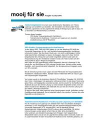
1 Introduction1 IntroductionThe Orion is a climate computer which isapplied to houses, where the ventilationcan be controlled: naturally, proportionallyand/or in stages. To maintain thenegative pressure constant, it is possibleto control the air inlet by making use of anextra negative pressure sensor. Theheating and cooling are operated bymeans of relay contacts. If an extra airhumidity sensor is used, the cooling canswitch off when the relative air humiditybecomes too high.The Orion makes use of extra timers,which have the advantage to set andcontrol the feeding-, water- and lightingsystem. At the same time, food and waterconsumption can be recorded becausethe Orion includes inputs for a feedweigher and water counter. Egg counting,bird weighing, operation of outlet doors and nests are also possible with the Orion.1472580369.30AABecause of the graphic display and the function- and navigation keys, the control communicates with clearlanguage independent symbols that immediately makes sense to the user. This makes it possible to makeuse of curves at important settings, when for example the desired temperature is automatically adjusted tothe age of the birds.By using the advanced communication module and the Rainbow+ management system, the Orion can beremote controlled from your home pc. Here too, user friendliness and graphic display were the points ofdeparture.At a single glance the user gets an overallview of all his production houses, whatsystems in said houses are activated and ifan alarm has been released in one ofthem.Orion-P / 03 1
2 Operation2 OperationThe Orion is provided with several keys and a graphic display. The keys can be divided into:Function keys:ControlsFeed / Water / TimersManagementAlarmDiagnosisInstallation / System settingsNumber keys:Numerical inputNavigation keys:Move cursorIncrease value /Previous lineDecrease value /Next lineMove cursor /Correction numerical inputConfirm value2.1 The readoutOn the display, the information can be presented in different ways. The most important ways will be explainedin this chapter.Press :Main group readoutSettings readout2 Orion-P / 03
2 OperationAll current data and/or status of the settings are visible in the main group. The data rely upon measured andcalculated values and can be retrieved by pressing the key (Controls), (Feed / Water / Timers) or(Management).The data in the main group cannot be altered. If you wish to alter settings which relate to the control from themain group, you press . Then you will make the so-called 'Settings readout' appear. When you press ,you will return to the main group readout. When the key is not touched for 5 minutes, the main group readoutof the temperature will appear automatically (= measured room temperature).In the enclosure 'Setting list', at the back of this manual, you find a view of the possible main groups andsettings. Data which relates to controls that are not activated will automatically be skipped and thereforecannot be retrieved.2.2 Retrieving and altering settingsPress the desired Function key ( , or ). The main group readout will now appear. By pressing , theSetting readout will appear. With or you can retrieve the correct setting.For example: Set Temperature:Change: or Confirm:Example: change Set Temperature from 21.0°C into 22.0°C.- Select : The Main group readout 'Temperature' appears;- Select : the Settings readout appears;- Select : the cursor moves to the value;- Select 10x or enter with the number keys the value 22;- Select : the setting has changed.Remarks:- If you do not wish to confirm the changed value during alteration (with the number keys), select. Theold setting will re-appear again on the display and the cursor will return to the starting position.- With this key , you can delete the last entered number.- Changes with the keys and cannot be corrected with the keys or .Changing settings containing several values, such as with curves or starting/stopping times, are activateddifferently. The following chapter describes the curves, whereas settings with starting / stopping times aredescribed in chapter 2.4.At the controls natural ventilation (ridge flaps) and inlet flaps the control can be divided in several zones.Maximum three ridge flaps and maximum 3 inlet flaps on the left and 3 inlet flaps on the right. The [1], [2], or[3] indicates to which control the setting is related. At the (lighting) timers, a maximum of 4 timers is possible.This is indicated with [1], [2], [3], or [4].Orion-P / 03 3
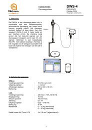
2 Operation2.3 CurvesA curve is a setting that, as time goes by, automatically adjusts itself. In a curve, a maximum of ten settingscan be introduced containing a day value for every setting that indicates the number of days, after which thecorresponding setting must be reached.Example: Set temperature curveSet temp.34322825232019Day Temp.0 °C-3 25 °C-1 28 °C0 34 °C3 32 °C7 28 °C14 25 °C21 23 °C35 20 °C42 19 °C-3 -1 0 3 7 14 21 35 42DaysThe set value is calculated by means of the day counter and the settings in the curve. The illustration aboveshows that the set temperature on the 7 th day is equal to 28°C and on the 21 st day equal to 23°C.The Orion contains curves for the following settings:- set temperature - minimum position air inlet flaps- minimum ventilation - maximum position air inlet flaps- maximum ventilation - set value RH- minimum damper - set value CO 2- maximum damperAt installation the information can be entered, whether or not curves will be applied. If not, the settings maybe retrieved and changed in the normal way. If the curve system is used, then this will be indicated at thesetting with .2.3.1 Retrieving and altering a curveBefore retrieving a curve, first the setting of the curve must be called for (see chapter 2.2). After retrieving thesetting, the calculated curve value will appear. By pressing , the cursor moves to the calculated curvevalue. Pressing once again , the first line of the curve will appear:4 Orion-P / 03
2 OperationThis may look like this:With or you are able to retrieve the previous or next curve-line. Then, go to the day value by pressingor . With , or the number keys you can increase or decrease this value and confirm with . Thecursor then goes to the setting of the corresponding day value, where it can be changed the same way. If thecurve points are set, you can exit the curve with .Remarks- At the first curve line, it is possible to rise or lower the entire curve (temporarily);= absolute rise; = relative rise (percentage).- If there is only one curve point set in the curve, then no setting for 'rise / lowering' is possible.- If the calculated curve value is altered in the Settings readout, then this will result in an adjustment in theset 'rise / lowering' of the curve;- A maximum of 10 curve points is possible; It is not necessary to enter all curve points. The value betweentwo points are calculated linear. From the last curve point, the value remains constant.- At the last curve line, the day value is set at 0; When entering a value, a curve point is added. This curvepoint is placed in the right order in the curve immediately.- When placing a 0 for the day value at a curve point, the curve point will be removed (the curve point at day0 cannot be removed).2.3.2 Day numberThe setting 'day number' is a counter. Every night at 24:00 hours, the computer heightens the day numberwith '1'. The day number indicates where the computer must check in the curves. From this point on, thecalculated curve value is definite.Example:At day 23 the calculated curve value is 22,6°CWhen housing a new flock of birds, the day number must be set back to '0'. By placing the day number on forexample -3, the computer will use the next 3 days to heat the house slowly to the desired temperature. Aswhere on day '0' the animals can be placed in the house (see example 'Set temperature curve').2.4 Timer settingsTimers are used for functions that must switch on predefined times on daily basis. Every timer has amaximum of 24 switch times. Switch times can be set in two ways:• ' Duration' = 0 minutes, the relay contact is switched on at the set ON-time and switched off at the setOFF-time.• ' Duration' > 0 minutes, the relay contact is switched on at the set ON-time for a period that is set at'duration'.Orion-P / 03 5
2 OperationAfter retrieving the setting 'clock' , you can retrieve the ON/OFF times by pressing the key. You can leafthrough the set times with the or key.ON/OFF timesON time + running timeorAlteringFirst jump with the or key to the line where the ON and OFF time must be altered. Jump with the keyto the time that must be altered. Hours and minutes can be alerted separately. Confirm the altering with thekey, after entering the value. The cursor jumps automatically to the next position.With feed and water systems it is possible that the switching time lines are extended with apercentage. These percentages define the feed amount that must be delivered at that switchingtime.AddingNew ON and OFF times can be added at the bottom at . If al the desired times are set you can leavethe timer menu with . The times are sorted automatically when leaving the timer readout.RemovingIf an ON time and OFF time are equal to each other, then these times are deleted after leaving the readout. Ifonly ON times are applied then a set time will be removed when this time is altered into .Linked timersWhen a timer is linked to another timer, the ON/OFF times of the linked timer will alter automatically when theON/OFF times of the leading timer are altered. The ON-time as well as the OFF-time can be linked to theON-time ( ), or to the OFF-time ( ) of the leading timer ( = not connected). Each linked time shouldbe set as a time difference ( ) in minutes.6 Orion-P / 03
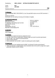
2 OperationThis example shows the difference between a water timer that is linked to the main light timer and aindependent water timer.Main LightingONOFF6:0019:00TimeMain LightingOFFONOFF-60m 240m -300m 60mWaterONOFFWaterONOFF5:00 10:00 14:00 20:00 5:00 10:00 14:00 20:00TimeTimeWater OFF ON OFF ON OFFWaterOFFONOFFONOFFWater timer independantWater timer connectedTimer curve (feeding)A timer curve can be used if the feeding times should depend on the age ofthe birds. The feeding times alter stepwise (not gradually). When a curve dayis reached, the new feeding time will be applied. It is possible to set severalfeeding times each a day.In case of rationed feeding, a feeding time includes a percentage. Thepercentage defines the feed ratio of the corresponding feeding turn.2.5 Remote controlIf the Orion is operated by means of Remote+, then this visible at tab .Normal operationOperation by means of a remote control (for example Remote+)Orion-P / 03 7
4 Controls3 Controls (F1)Every control (ventilation, air inlet, heating etc) starts from its set temperature, as entered at the temperaturecontrol . The ventilation control immediately starts from the set temperature. A temperature differentialfor the other controls, in regard to the set temperature, may be entered. This implies that changing the settemperature, this will affect all other controls.3.1 Ventilation controlThe Orion can control a number of different ventilation systems. They all start from the same principle. Thebelow mentioned example starts from a ventilation system with 6 steps. In the control delineation of theventilation control, three elements are to be distinguished:1. the room temperature is lower than the set temperature;During this stage, ventilation is minimum. The minimum ventilation position is to be set with the setting'minimum ventilation' ( ).2. the room temperature exceeds the set temperature but is lower than the set temperature plusproportional range;Ventilation will adopt a value between minimum- and maximum.3. the room temperature exceeds the se temperature plus proportional range.The ventilation will have reached the maximum level, as set at 'maximum ventilation' ( ).Settings:VentilationAlarmAlarmSet temperatureSet night temperatureMinimum ventilationMaximum ventilationProportional rangeMin. alarm differenceMax. alarm differenceAbs. max. al. differenceRoom temp.Ventilation Min ventilation Min.....Max Max ventilationMax temp.Alarm Min temp. Abs max temp.The minimum and maximum temperature alarms are linked to the ventilation control. The working andsettings are explained in the chapter 'Alarms'.8 Orion-P / 03
4 Controls3.1.1 The Ventilation systemThe ventilation system can be composed out of basic-, natural- and/or tunnel ventilation. The construction ofthe ventilation system is set up by your installer during the installation procedure of the Orion.Basic ventilation (mechanical ventilation)The basic ventilation system may consist of adjustable fans (proportional fans) and non-adjustable fans(on/off-fans). These on/off-fans are controlled in maximum 16 groups. The proportional ventilation part canautomatically switch back when an on/off-fan group is switched, in order to obtain an as linear as possibleventilation pattern.If there are no proportional fans installed, then it is possible to cyclic switch on and off a part of the on/off-fansin order to obtain an as linear as possible ventilation pattern.If the ventilation system also includes natural- and / or tunnel ventilation, then it will change to natural- ortunnel ventilation after the basic ventilation has reached its maximum capacity.Natural ventilationWith natural ventilation, the basic ventilation is switched off. The inlet flaps, set at basic ventilation, open,close all the way or remain controlling. The inlet flaps set at natural ventilation take over the ventilation untilthe maximum flap position is reached. When tunnel ventilation has also been set, there will be a switch totunnel ventilation.Tunnel ventilationWith tunnel ventilation, (a part of) the basic ventilation is switched off. A maximum of 16 groups of fans canbe switched on at tunnel ventilation. The inlet flaps, set at basic- and / or natural ventilation, open, close allthe way or remain controlling.3.1.2 Day/night set temperatureThe Orion has the possibility to make a distinction between the set temperature during the day and during thenight. This possibility must be activated during the installation procedure. In that case you are able to set at'Set night' ( ) a temperature difference with regard to the 'set temperature' ( ).The day/night periods are set at the menu 'Time and date' (see chapter 3.13). During the night period the settemperature will be equal to 'Set night' ( ). The transition from the day temperature to the night temperaturetakes place gradually. This to avoid ventilation jumps.3.1.3 Shut down fans1) Press at the settings read on ' Fans out of use'. The boxes matchwith the fans that can be shut down.2) Shut down a fan by putting the symbol in the box. Navigate with thekeys. Shut down a by means of the key. Activate a fan withthe key. The percentage indicates the part of the ventilation that isswitched off, split up into basic ventilation (left) and tunnel ventilation(right).When the available ventilation capacity isn't sufficient for the required ventilation, the Orion givesthe alarm call 'Ventilation capacity not reached'Orion-P / 03 9
4 Controls3.1.4 Ventilation on basis of m 3 /hour/kgWith ventilation on basis of m 3 /hour/kg the ventilation minimum and ventilation maximum is adapted to theaim weight of the birds, the number of birds in the house, and the ventilation level per kg bird (m 3 /hour/kg).Example• Aim weight of the birds in the house: 950g/bird.• Number of birds in the house: 10 000 birds.• Minimum ventilation level: 1,0 m 3 /hours/kg.• Maximum ventilation level: 3,6 m 3 /hours/kg.• Maximum ventilation of the house 100 000 m 3 /hours.Then the minimum ventilation level is: 0,950 * 10 000 * 1,0 = 9500 m 3 /hour (9,5% form the maximumventilation capacity). The maximum ventilation capacity is: 0,950 * 10 000 * 3,6 = 34200 m 3 /hour (34,2% fromthe maximum ventilation capacity).Ventilation based on m 3 /uur/kg must have been activated during the installation procedure. For this ventilationprinciple you need to enter the next data into the Orion.• Growth curve.• Stocking norm.• Number of birds in the house.• The minimum ventilation curve• The maximum ventilation curve.Growth curveThe growth curve is set at tab . If bird weighing is applied, then the Orion uses the growth curve of the birdweighing function (see chapter 4.11). If bird weighing isn't used, the growth curve must be set in the menu'Body weight'. Chapter 2.3 explains how a curve has to be set.'Settings:Set valueStocking normThe stocking norm is the quantity of animals that are normally present in the house (house capacity). This isa system setting, see chapter 8.3.6)Actual number of birds in the houseThe actual number of birds in the house must be kept up at the management section (see chapter 5).Setting the minimum and maximum ventilation curveIf all the data are set correctly, you are able to set the curves for the minimum and maximum ventilation.Chapter 2.3 gives more information about setting a curve. You should set the ventilation level as apercentage. The Orion calculates automatically the matching ventilation in m 3 /hour/kg ( ) (on basis of thestocking norm). If the set percentage doesn't result in the desired m 3 /hour/kg, then you have to alter thepercentage with the keys or by entering a different percentage.10 Orion-P / 03
4 Controlsminimum ventilation curvemaximum ventilation curveAdapting the ventilation curveWhen the number of birds in the house increases, for example caused by mortality or by provisionalremoving, then the maximum en minimum ventilation level will be adapted automatically. This is displayedat .By keeping up the mortality and the drop outs with the management function, the ventilation level isautomatically adapted.It is also possible to adapt the curve independently from the number of birds in the house. This can be doneby increasing or decreasing the curve with a percentage is ( , see chapter 2.3).If you are using a flock of birds that have a different growth curve then you have to adapt the growth curvefirst. And after that the minimum and maximum ventilation curve.3.2 Damper controlFor a ventilation system with proportional ventilation, it may be necessary to lower the ventilation quantity inthe minimum area. The damper can be used for this situation. The setting 'temperature difference damper'( ) makes it possible to have the damper respond earlier (value negative) or later than the ventilationcontrol.Settings:DamperSet temp. (ventilation)Temperature differencedamperMin. position damperMax. position damperProportional range damperRoom temp.Damper Min position Min.....Max. Max position damperOrion-P / 03 11
4 Controls3.3 Air inlet controlThe inlet flaps can be controlled in three different ways:• on the basis of temperature (independent from ventilation);• on the basis of the ventilation position;• on the basis of negative pressure.Your installer will indicate in the installation procedure of the Orion how the air inlet control must function.3.3.1 Control on basis of the temperatureThis type of control can be applied for the basic ventilation and will always be applied with ridge outlets andthe air inlets of natural ventilation.The controlThe air inlets are regulated according the same principle as the ventilation control. Dependent on themeasured temperature, the air inlets are driven into a certain position. Each air inlet (with a maximum of 6)may have its own temperature difference with regard to the set ventilation temperature ( ). Thistemperature difference must be entered at the setting 'temperature difference air inlet' ( ). This makes itpossible to let the air inlets respond earlier (value negative) or later than the ventilation control.Settings:Inlet flapAlarmAlarmSet temp. (ventilation)Temperature difference airinletMinimum inlet positionMaximum inlet positionProp. Range air inletMin. alarm differenceMax. alarm differenceAbs. max. al. differenceRoom temp.Inlet flap Min. flap position Min.....Max Max. flap positionAlarmMin temp.Max temp.Abs max temp.If the air inlet control works on the basis of temperature, there will also be minimum and maximumtemperature alarms linked to this control. The working and settings are explained in the chapter 'Alarms'.12 Orion-P / 03
4 ControlsSummer/winter controlThe air inlet control bas don temperature can be extended with a summer/winter control for summer/winterair inlets. See chapter 8.5.1.2 for more information.Position summer inletPosition winter inletMeasured negative pressureInlets separateWith the air inlet control based on the room temperature you are able to set a different set temperature foreach air inlet group. For example: when the house is divided into different temperature zones. If you pressafter you altered the setting 'temperature difference air inlet' ( ) then the temperature difference for allthe air inlet groups is the same. If you press at this setting you are able to set different set temperaturesfor each air inlet group.If during the installation procedure 'inlets separate' is activated, you are able to make more different settingsfor each air inlet group; namely the minimum inlet position, the maximum inlet position and the proportionalrange. Altering these settings is similar to altering the different set temperatures.If the curves option is activated, you are able to set the minimum and maximum flap position with a separatecurve for each air inlet group. Chapter 2.3 gives more information about setting a curve.Settings read-out Current minimum flap position Curve: Inlet 1 Inlet 2 Inlet 3In the main group read out the average flap position is displayed.Influences on the flap positionOther controls, like the cooling control, can have an influence on the flap position. The wind can also have aninfluence on the flap position. See chapter 8.5 (system settings).3.3.2 Control on basis of the negative pressureWith basic ventilation and tunnel ventilation it is possible to control the air inlets on basis of the negativepressure.From the measured negative pressure, the air inlets are driven into a certain position. As long as themeasured negative pressure is lower than the set negative pressure (minus hysteresis), the air inlets willbe closing until the negative pressure enters the dead zone again. In reverse order, the flaps are openingwhen the negative pressure is higher than the set negative pressure (plus hysteresis). As soon as thenegative pressure drops down to the dead zone again, the opening of the flaps is halted.Orion-P / 03 13
4 ControlsThe step width, cycle time etc. for opening and closing of the flaps are system settings. Next to it is possibleto set the minimum and maximum opening of the air inlets.Inlet flapAlarmAlarmSettings:Set negative pressureMinimum flap positionMaximum flap positionMin. pressure alarmMax. pressure alarmNeutralzoneInlet flap Alarm Closing flap Opening flapNeg. press. (Pa)AlarmIf an outside temperature sensor isinstalled and curves are used, the desiredvalue of the negative pressure depends onthe outside temperature. There are twoset-points possible.• When the outside temperature dropsbelow the temperature as set first ( ),the set value for the pressure will equalthe pressure as first set ( ).• When the outside temperature exceedsthe secondly set temperature ( ), theOutside temp.set value will equal the second pressure( ).• If the outside temperature lies somewhere between the two set temperatures, the set value for thepressure will be in between these two set values for the set pressure.Pressing brings you back to the calculated value for the set pressure.The minimum and maximum pressure alarms are explained in the chapter 'Alarms' (see chapter 6).Cyclically coupledIf the flap control is cyclically coupled with the ventilation, then the flaps are opened further when theventilation is switched on, and further closed when the ventilations switches off. See the system settings formore information (chapter 8.5.2.4).Temperature correctionSet value negativepressureWith air inlets that are controlled on the basis of negative pressure it is possible to correct the position of theflaps on basis of the temperature in the zone. If the temperature in the zone rises above the average roomtemperature then the flap will be opened further. See chapter 8.5.2.2 for more information.2518-101514 Orion-P / 03
4 ControlsSplit baffleWith split baffle it is possible to drive the incoming air in two different directions by means of two air inletflaps. The ratio between both inlet openings depends on the outside temperature. The flap ratio is set at'Ratio flap 1:flap 2'.The setting is defined by the ratio value of flap 1. The ratio value of flap 2 is calculated automatically(100 minus the ratio value of flap 1).The ratio value of flap 1 can depend on the outside temperature. If the outside temperature isbelow 10°C then the ratio flap1:flap2 is equal to30:70; If the outside temperature is above 25°Cthen the ratio flap1:flap2 is equal to 80:20.Between 10 and 25°C the ratio of 30:70 will beadapted gradually to 80:20. For example: at 17,5°Cthe ratio will be 55:45.A ratio of 80:20 means that flap 1 is always opened4 times further than flap 2.If the negative pressure is too low, then the flaps10 25Outside temp.are opened until the minimum flap position isreached or until the negative pressure is adequate.In the minimum flap position, the least closed flap is set to the minimum position. The other valve will have anopening according to calculated ratio. If the ratio is 80:20 and the minimum flap position is 10%, then flap 1will be opened 10% and flap 2 will be opened 2,5%. If the ratio is 50:50 then both flaps will be opened 10%. Ifthe minimum flap position is 0% then both flaps will be closed.If the negative pressure is too high, then the flaps are opened until the maximum flap position is reached oruntil the negative pressure is adequate. In the maximum flap position, the farthest opened flap is set to themaximum position. The other valve will have an opening according to calculated ratio. If the ratio is 80:20 andthe maximum flap position is 100%, then flap 1 will be opened 100% and flap 2 will be opened 25%. If theratio is 50:50 then both flaps will be opened 100%.Influences on the flap positionRatioflap 1 (%)The wind can also have an influence on the flap position. See chapter 8.5 (system settings).80303.3.3 Control on the basis of the ventilation position (synchronous)With basic ventilation and tunnel ventilation it is possible to link the flap control with the ventilation control.If the control of the inlet flaps is linked to the ventilation level, then the flap position will change together withthe ventilation level. You can set the relation between the ventilation level and flap position by means of aflap-ventilation curve.Orion-P / 03 15
4 ControlsExample: flap-ventilation curveInlet flap10085Ventilation Flap0 % 0 %1 % 2 %10 % 8 %25 % 25 %50 % 55 %75 % 85 %100 % 100 %55258201 10 2550 75 100VentilationAt each line, you must enter a ventilation level ( ) and its matching flapposition ( ). Chapter 2.3 gives more information about curves.The Orion uses a standard curve with the next 6 points: 1%-1%,10%-10%, 25%-25%, 50%-50%, 75%-75%, 100%-100%.Cyclically coupledIf the flap control is cyclically coupled with the ventilation, then the flaps are opened further when theventilation is switched on, and further closed when the ventilations switches off. See the system settings formore information (chapter 8.5.3).Temperature correctionWith air inlets that are linked to the ventilation level it is possible to correct the position of the flaps on basis ofthe temperature in the zone. If the temperature in the zone rises above the average room temperature thenthe flap will be opened further. See chapter 8.5.3 for more information.3.4 Winter gardenIt is possible to control a flap for each winter garden (1x left, 1x right). This control is on the basis oftemperature. When a wind direction and wind velocity is being measured, a correction on the chosen positionis possible. There is no minimum and maximum temperature alarm at the winter garden control.16 Orion-P / 03
4 ControlsWinter gardenSettings:Set temp. winter gardenMinimum flap positionMaximum flap positionProportional rangeTemperatureWinter garden Min position Min.....Max Max flapposition3.5 Mixing ventilationFor the mixing ventilation there are 2 types of controls available:• ON / OFF contact; or• proportional control via 0-10V signal.The type of control is set by your installer during the installation procedure. For both controls it is also neededthat is indicated how these are controlled. For the set temperature you can choose out of the next controltypes.• temperature difference with regard to the set temperature ventilation; or• temperature difference between the assigned sensors of the mixing ventilation; or• absolute fixed temperature.During the installation procedure you are able to activate the next functions that have influence on the mixingventilation.• Switching off the mixing ventilation when the tunnel ventilation becomes active.• Switching on the mixing ventilation when a heating device becomes active. Then you are able to set a lagtime, see chapter 8.7.3.5.1 ON / OFF contactThe contact for mixing ventilation is activated when the measured temperature of the mixing ventilationcontrol becomes higher than the set temperature mixing ventilation (= for example: 'set temperatureventilation' plus the 'temperature difference'). The contact disconnects when the temperature becomes lowerthan the 'set temperature mixing ventilation' minus 'hysteresis'. The hysteresis is adjustable at the systemsettings.Orion-P / 03 17
4 ControlsMixing ventilationONSettings:Set temp. mixing ventilationOFFRoom temp.Mixing ventilationOFFONIn short: ON :OFF :at a temperature higher than 'set temperature mixing ventilation';at a temperature lower than 'set temperature mixing ventilation' minus 'hysteresis'.3.5.2 Proportional control through 0-10V signalThe 0-10V mixing ventilation control operates by means of a proportional range. As long as the temperatureis lower than the 'set temperature mixing ventilation' (for example temperature difference between sensors),the mixing ventilation will remain minimum. If the temperature is higher than the 'set temperature mixingventilation' plus 'proportional range', the mixing ventilation will be maximal.Mixing ventilationSettings:Ser temp. mixingventilationMin. mixing ventilationMax. mixing ventilationProportional rangeRoom temp.Mixing ventilation Min position Min.....Max Max mixing ventilation18 Orion-P / 03
4 Controls3.6 Mix-air ventilationMix-air ventilation is blowing hot air from the ridge over the litter. The purpose of this is to reduce theammonia emission. In the Netherlands, it is legally obligated that use of the mix-air ventilation is recorded. Sothe Orion records the use and the settings of the mix-air ventilation automatically. Because of the limitedmemory of the Orion it is needed that the recorded data are took out of the Orion and is being savedsomewhere else. This can be done with the management program 'Rainbow'.The mix-air ventilation is set by means of a curve. The curve defines the ventilation level of the mix-air fans.Mix airventilation100DayVentilation0 0 %1 0 %2 10 %40 100 %Set ventilation500-2 0 1 210203013In the example above on day 13 the ventilation level is 37%.40DaysThe Orion has four options for recording the mix-air ventilation. The method of registration is set during theinstallation procedure. The next methods are available.• Hour-counterThe Orion counts the number of hours that the mix-air ventilation is above 0%.• kWh-counterThe Orion counts the number of hours that the mix-air ventilation is above 0%. Next to it, the electricityconsumption, in kWh, is recorded with a pulse counter (1 pulse = 1 kWh).• Revolution-counterThe Orion counts the number of hours that the revolution counter records (the measured ventilation isabove 1%).• Measuring-fanThe Orion counts the number of hours that the measuring fan records when the mix-air fans are running(the measured ventilation is above 1%).- measured ventilation (revolution-counter or measuring fan),- set value (hour-counter or kWh-counter)set value accordingto the curvetotal number ofrunning hourstotal number of kWh (only visibleif this option is activated)number of runninghours todaynumber of kWh today (Onlyvisible if this option is activated)Orion-P / 03 19
4 Controls3.7 HeatingFor the heating you can choose out of 2 types of controls:• ON / OFF contacts; or• proportional control through 0-10V signal.The type of control is set by your installer during the installation procedure.3.7.1 ON / OFF contactsThe heating contacts are activated when the measured temperature of the heating control drops below the'set temperature (ventilation)' plus the 'temperature difference heating'. The contacts will be disconnectedagain when the temperature exceeds the 'set temperature' plus the 'temperature difference heating' plus'hysteresis'. The hysteresis can vary between 0 and 1,0°C. Dependent on how high the room temperaturebecomes after switching off the heating, the Orion will automatically adjust this.HeatingSettings:Set temperature(ventilation)Temperature differenceheatingRoom temp.Heating Heating ON Heating OFFIn short: ON :OFF :at a temperature lower than 'set temperature' plus 'temperature difference' heating;at a temperature higher than 'set temperature' plus 'temperature difference heating'plus 'hysteresis'.3.7.2 Proportional control through 0-10V signalThe 0-10V heating control operates by means of a pulse/pause system. As long as the temperature is lowerthan the 'set temperature (ventilation)' plus the 'temperature difference heating', the signal will increase everycycle time with a certain step width, until the signal is maximum (for example 10V), or until the temperatureexceeds the 'set temperature (ventilation)' plus the 'temperature difference heating'.20 Orion-P / 03
4 ControlsAfter the heating is switched on and the temperature becomes higher than the 'set temperature (ventilation)'plus the 'temperature difference heating' plus 'hysteresis', the signal will reduce stepwise.The step width and cycle time for increasing and decreasing the signal are separately adjustable (for thesesettings we refer to the system settings of chapter 8).HeatingMaximumSettings:Set temp. (ventilation)Temperature differenceheatingMinimumRoom temp.Heating Heating Max Heating MinIn short: Maximum / increase :Minimum / decrease :at a temperature lower than 'set temperature' plus temperature differentialheating;at a temperature higher than 'set temperature' plus 'temperature difference'plus 'hysteresis'.3.8 CoolingThe contact for cooling switches on basis of a fixed set temperature (only the setting set temperature cooling)or on basis of a temperature difference with regard to the set temperature (ventilation), as described below.Which of these options is used is set during installation procedure.CoolingONSettings:Set temperature (ventilation)Temp. Difference coolingOFFRoom temp.CoolingOFFOrion-P / 03 21
4 ControlsWhether cooling is allowed depends on the RH value measured in the house. The moment the RH exceedsthe 'Maximum value RH cooling OFF' ( ), cooling will be stopped.The maximum RH value whereby cooling is stillallowed is not a constant value but depends onthe measured room temperature. If curves areused, two set points for the room temperatureappear together with their maximum RH.• With a room temperature beneath the firsttemperature entered ( ), the maximum RHequals the first RH value entered ( ).• With a room temperature exceeding thesecond RH value ( ), the maximum RHMax value RHCooling OFFequals the second RH value entered ( ).• With a room temperature in between the twoset temperatures, the maximum RH will be inbetween the two set values for the RH.Pressing , the calculated value for the maximum RH will appear.958525 35Room temp.3.9 Humidity+ONHumidificationVentilationAlarmSettings:Set value RHMax. RH alarmRH difference humidifyingOFFAir humidityHumidificationONOFFVentilation+No raiseRaisingAlarmMax RHHumidifierWhen the measured RH is lower than the 'set value humidity' min 'RH difference humidifying', the contact forhumidifier will switch on.Tuning the ventilationIf the measured air humidity exceeds the 'set value humidity' (curve), the ventilation level will increase. Whenapplied, the air inlets and the damper position will also be adapted. If the humidity exceeds the 'Set value RHplus 'proportional range increase ventilation' (system setting, see chapter 8.10), the increase is maximal.AlarmWhen the RH still becomes too high, in spite of the ventilation rise, a Maximum RH Alarm can be generated.22 Orion-P / 03
4 Controls3.10 CO 2 controlIf the measured CO 2 level is above the set value CO 2 (curve), then the Ventilation level will increase. Whenthe measured CO 2 level rises above the 'Ste value CO 2 ' plus 'Proportional range increase ventilation in favourof the CO 2 level' (adjustable system setting) then the increase is maximal. The maximum increase at heatingON as well at heating OFF can also be set at the system settings (see chapter 8.11).VentilationincreaseMaxSettings:Set value CO 2Max. CO 2 alarmAlarm0%CO level2VentilationNo raiseRaisingAlarmMax CO 2The ventilation rise applies to the ventilation control as well as the air inlet control. When the ventilationcontrol works together with a damper control, then a correction for this control can also be adjusted.3.11 Common controlsThe universal controls are proportional controls (maximum 4) for universal use. For the set temperature ofthese controls can be chosen from:• differential temperature with regard to the set temperature ventilation; or• absolute fixed temperature.Common controlUNISettings:Set temperatureuniversal controlMin. universal controlMax. universal controlProportional rangeTemperatureUNICommon control Min. Min.....Max Max common controlThe universal controls operate only on the basis of temperature and are independent from the measured RH,wind direction and / or wind velocity. Also, no minimum and maximum temperature alarms are linked to thesecontrols.Orion-P / 03 23
4 Controls3.12 Manure dryingThe Orion can control maximal two air mixers or heat exchangers. The intake fan and exhaust fan of the heatexchanger can run with several speeds if a frequency controller is used. You may use this for different ratesof speed during daytime and night time.The heating can be controlled by a relay contact as well as by 0-10V signal. The cooling is operated by arelay contact.The timers for the manure drying make it possible to switch ON/OFF the entire control at certain times. Also, thestart and stop times for cleaning and the day/night periods can be programmed.Air mixerDuct temperature(actual)Heat exchangerDuct temperature(actual)Control accordingto the day periodSet temperatureductHeating levelPosition outside inletContribution of the intake fan to the3ventiation capacity in m /h/birdControl accordingto the night periodSet temperatureductHeating levelVentilation level intake fanContribution of the intake fan to the3ventiation capacity in m /h/birdThe ventilation capacity may be included with the house ventilation. This should be set in theinstallation procedure. If enabled, the ventilation of the house will turn down when the intake fan ofthe manure drying is active.3.12.1 Air mixerIn the air mixing chamber the outside-air is mixed with house-air; based upon the duct temperature. Whenthe temperature becomes too low, extra heating is possible. On the other hand, when the temperature is toohigh, cooling is also possible. During the cooling period the outside flap is closed. Then, with an extra contact,the cooling can be activated. However, if the cooling is controlled by an exterior system, the outside flap willalso be closed during the cooling.Settings:Set temperature ductMin. position outside flapMax. position outside flapProportional range outside flapHeating differenceTemp. diff. outside flap closedTemp. difference coolingMinimum alarm differenceMaximum alarm differenceControl ON / OFFStart / Stop times cleaningTimes Day / NightIntake fan (day level)Intake fan (night level)Remarks:• marked settings are curves. Read chapter 2.3 about curves. When the house ventilation is basedon m 3 /uur/kg, the manure drying also is based on m 3 /uur/kg, read chapter 3.1.4 for more information.• The ventilation capacity of the heat exchanger can be included in the total house ventilation. This is setduring the installation procedure. The house ventilation will turn down when the manure drying systemis active.24 Orion-P / 03
4 ControlsIn the control delineation of the air mixer control, 9 elements are to be distinguished:Outside flapAlarmAlarmSYSDuct temp.1 2 3 4 5 6 7 8 9Outside flapInlet fanClosedOFFAbs min Min Min...Max Max pos.(SYS)Heating(SYS)DayNightCooling(SYS)ClosedOFFHeatingOFFONOFFCoolingOFF ON OFFAlarmMin temp.Max temp.For every element, there is a description of the different controls:The duct temperature is too low;• the outside flap is in its absolute minimum position (SYS, chapter 8.12.1)• the computer indicates a minimum temperature alarm• if the air mixer shuts down in case of a minimum alarm, the outside flap will close and the intake fan,heating and cooling will switch off. (Whether the air mixer shuts down at minimum alarm is set in theinstallation procedure.)The control is in the 'heating' area;• the outside flap is in its absolute minimum position (SYS, chapter 8.12.1)• de intake fan is at the 'heating' position (SYS, 8.12.2)• the heating is switched on, the cooling is switched off• there is no alarmThe control is in the area 'minimum + heating';• the outside flap is in the position 'minimum position outside flap'• the intake fan runs on 'day level' or 'night level'• the heating is switched on. With proportional heating the heating will increase stepwise. The width ofthe steps depends on the proportional range of the heating (SYS, chapter 8.12.4)• the cooling is switched off• there is no alarmOrion-P / 03 25
4 ControlsThe control is in the area 'minimum' (duct temperature is lower than set temperature);• the outside flap is in the position 'minimum position outside flap'• the intake fan runs on 'day level' or 'night level'• the heating is still switched on (depending on the hysteresis)• the cooling is switched off• there is no alarmThe control is in the area 'proportional range'• the outside flap is in a position between the 'minimum position outside flap' and the 'maximumposition outside flap'• the intake fan runs at 'day level' or 'night level'• both heating and the cooling are switched off• there is no alarmThe control is in the area 'maximum' (duct temperature is higher than the set temperature plusproportional range);• the outside flap is in the position 'maximum position outside flap'• the intake fan runs on 'day level' or 'night level'• both heating and the cooling are switched off• there is no alarmThe control is in the area 'cooling';• the outside flap is closed• the intake fan runs on 'cooling level' (SYS, chapter 8.12.2)• the heating is switched off• the cooling is still switched on (depending on the hysteresis)• there is no alarmThe control is in the area 'cooling + contact';• the outside flap is closed• the intake fan runs on 'cooling level' (SYS, chapter 8.12.2)• the heating is switched off• the cooling is switched on• there is no alarmThe duct temperature is too high;• the outside flap is closed• the intake fan is switched off• both heating and cooling are switched off• the computer indicates a maximum temperature alarmAll of the above is based on a proportional control for the heating and for the inlet fan. In the installationprocedure it is optional to add a contact for these controls. The contact switches off at 0% en switches on at alevel between 1% and 100%.In order to program the times for the inlet fan to run on the 'day level' and the 'night level, use the timerday/night (chapter 3.12.3).The minimum and maximum alarms are explained in chapter 6 'Alarms'.3.12.2 Heat exchangerIn a heat exchanger, ducts separate the house-air and the outside air, which enables to heat or cool down100% outside air. The cold outside air is heated by house-air, which is lead out. In the summer, mist-sprayingdevices with (soil) water cool down the warm outside air, which sprinkle over the ducts. During the coolingperiod, the fan runs on a lower level. After that the sprayers are switched on with the cooling contact. If thecooling is controlled by an exterior system, the exhaust fan will also be put on a lower level during the coolingperiod. In the control delineation of the ventilation control, 8 elements are to be distinguished:26 Orion-P / 03
4 ControlsSettingsSet temperature ductHeating differenceTemp. difference exhaust fanTemp. difference coolingMinimum alarm differenceMaximum alarm differenceControl ON / OFFStart / Stop times cleaningTimes Day / NightIntake fan (day)Intake fan (night)exhaust fan (day)exhaust fan (night)Remarks:• marked settings are curves. Read chapter 2.3 about curves. When the house ventilation is basedon m 3 /uur/kg, the manure drying also is based on m 3 /uur/kg, read chapter 3.1.4 for more information.• The ventilation capacity of the heat exchanger can be included in the total house ventilation. This is setduring the installation procedure. The house ventilation will turn down when the manure drying systemis active.FanAlarmAlarmSYSDuct temp.Inlet fanExhaust fanHeating1OFFOFFOFF2 3 4 5 6 7 8DayHeatingCooling(SYS)Night(SYS)OFFDayHeatingCooling(SYS)Night(SYS)OFFONOFFCoolingOFFONOFFAlarmMin temp.Max temp.Orion-P / 03 27
4 ControlsFor every element, there is a description of the different controls: The duct temperature is too low;• the computer indicates a minimum temperature alarm• if the heat exchanger shuts down in case of a minimum alarm, the intake fan, exhaust fan, heatingand cooling will switch off. (Whether the air mixer shuts down at minimum alarm is set in theinstallation procedure.) The control is in the area 'heating';• the inlet fan runs on the level 'heating' (SYS, chapter 8.12.2)• the exhaust fan runs on the level 'heating' (SYS, chapter 8.12.3)• the heating is switched on , the cooling is switched off• there is no alarm The control is in the area 'ventilation + heating';• the inlet fan runs at 'day level' or 'night level'• the exhaust fan runs at 'day level' or 'night level'• the heating is switched on. With proportional heating the heating will increase stepwise. The width ofthe steps depend on the proportional range of the heating (SYS, chapter 8.12.4)• the cooling is switched off• there is no alarm The control is in the area 'ventilation';• the inlet fan runs at 'day level' or 'night level'• the exhaust fan runs at 'day level' or 'night level'• the heating is still switched on (depending on the hysteresis)• the cooling is switched off• there is no alarm The control is also in the area 'ventilation';• the same situation as in area 4 however, the heating is switched off The control is in the area 'cooling';• the inlet fan runs on the level 'cooling' (SYS, 8.12.2)• the exhaust fan runs on the level 'cooling' (SYS, chapter 8.12.3)• the heating is switched off• the cooling is still switched on (depending on the hysteresis)• there is no alarm The control is in the area 'cooling + contact';• the inlet fan runs on the level 'cooling' (SYS, chapter 8.12.2)• the exhaust fan runs on the level 'cooling' (SYS, chapter 8.12.3)• the heating is switched off• the cooling is switched on• there is no alarm The duct temperature is too high;• the inlet fan and the exhaust fan are switched off• both heating and cooling are switched off• the computer indicates a maximum temperature alarm28 Orion-P / 03
4 ControlsAll of the above is based on a proportional control for the heating, the inlet fan and the exhaust fan. In theinstallation procedure it is optional to add a switch contact to these controls. The contact switches off at 0%en switches on at a level between 1% and 100%.In order to program the times for the inlet fan and exhaust fan to run on the 'day level' and the 'night level, usethe timer day/night (chapter 3.12.3).The minimum and maximum alarms are explained in chapter 6 'Alarms'.3.12.3 TimersAt the setting 'manure drying' it is possible to retrieve and adjust a maximum of three timerson the settings in the installation procedure, these are:• Control ON/OFF• Start / Stop rinsing• Times Day / Night. DependingControl AAN/UITThis timer defines the part of the day in which the manure drying control must be active. See chapter 2.4 foradjusting the timer.Start / Stop rinsingWhen reaching a start time , the ventilation is switched off and the outside flap opens (only with airmixing device). Furthermore, the heating and/or the cooling are switched off. After 180 seconds the 'rinsing'contact is switched on. At the stop time , the contact 'rinsing' is switched off, the ventilation switches onand the outside flap moves to the right position. During rinsing time the minimum and maximum alarmsremain activated. See chapter 2.4 for adjusting the timer.Times Day / NightWhen the inlet fan and or exhaust fan are controlled proportionally, they can run on a different level duringday and during night. When a day time arrives , the inlet fan and the exhaust fan are going to run on theday ( ) level; when a night time arrives, they run on the night ( ) level. In the areas heating or coolingthe day and the night levels are not activated (chapter 3.12.1and 3.12.2). See chapter 2.4 for adjusting thetimer.Fan7:0018:00TimeInlet fanNightDayNightExhaust fanNightDayNightOrion-P / 03 29
4 Controls3.13 Time/dateTime and dateThe current time ( ) and date ( ) of the computer. At the settings read out the time and date can bealtered. The system setting 'Synchronise time' defines how the Orion handles the time settings (seechapter 8.13).Day counterHer you can set the day counter. Read for more information chapter 2.3 (curves).Time dayThe set temperature ventilation may have another value during the day period and the night period. Thisoption is set during the installation procedure. When the day period arrives the set temperature for theventilation control is put gradually on the 'Set temperature day' When the night period arrives theset temperature for the ventilation control is put gradually on the 'Set temperature night' the value 'Settemperature night' is a difference temperature with regard to the 'Set temperature day'.The transition from day to night and the opposing takes place gradually. The set temperature alters 0,1°Cevery 5 minutes. If you alter the 'set temperature day' or the 'set temperature night' then the gradual transitionisn't applied, also when you alter the day or night period.Fan7:0018:00TimeSet temperatureNightDayNight30 Orion-P / 03
4 Controls3.14 Weather stationThe weather station shows the next data.Outside temperatureWind direction. The arrow points to the direction where the wind comes from (like a weather vane).The exact wind direction can be retrieved at 'Diagnoses' (see chapter 7).Wind velocity.Relative humidity (RH) outside.The Orion is able to tune the position of the ridge flaps, damper and air inlet flaps on the basis of the windvelocity. The tuning takes place after a certain wind velocity. This can be set at 'Start wind correction' .Orion-P / 03 31
4 Feed / Water / Timers4 Feed / Water / Timers (F2)The groups feed, water and timers are time related. These can be set with separate timers or be linked to themain lighting control. The functions of these groups are enabled by your installer during the installationprocedure.4.1 Feed registrationThe registration of feed can be carried out in 4 different ways:• by a pulse counter; or• by a feed weigher; or• by a feeding computer; or• by silo weighing4.1.1 Pulse counterABECA. SiloB. Silo augerC. Pulse counterD. Cross augerEach pulse matches with a fixed amount of feed (to be set in the installation procedure) and is added to thetotal amount of feed consumption, and is subtracted from the silo contents.4.1.1.1 Main group read outFeed consumption today(until now)Feed consumption gram/bird:Today (until now)YesterdayDay before yesterdayFeed consumption gram/bird is only visible when bird management is enabled.32 Orion-P / 03
4 Feed / Water / Timers4.1.1.2 SettingsRegistration feed consumptionThe Orion records the feed consumption of each day. This can be read in the settings readout. ' Feed day[ 0]' is the feed consumption today. ' Feed day [-1]' and ' Feed day [-2]' is the feed consumptionyesterday and the day before yesterday. ' Total' gives the amount of feed that is consumed totally.By pressing you will enter the screen in which you can read thedivision per feed type. The consumption at 'Feed day [ 0]', and ' Total'may be altered manually.When you deleted the bird management data the feedconsumption will also be deleted (see chapter 5).Silo-contents (silo registration enabled)The feed registration by means of a pulse counter has the possibility toadministrate the feed consumption from one silo ' silo-contents'). Thenthere are three settings available.• Silo contents:The consumed food is subtracted automatically from the silo contents.If your feed supplier has filled up the silo then you can enter thesupplied quantity at ' silo xx contents'. The supplied quantity is addedto the actual silo contents. If the actual silo contents is for example 250 kg and you enter a silo-contents of10 000 kg then the total silo-contents will be 10250 kg.This is also applicable to a negative silo contents. If the actual silo contents is for example-250 kg and you enter a silo contents of 10 000 kg then the total silo contents in the Orion will be9750 kg.If you enter a silo contents of 0 kg then the actual silo contents will always alter into 0 kg. You can use thisfunction to nullify a negative silo contents. After you put the silo contents to 0 kg you can enter the real silocontents.• Silo min contents:At the moment the silo-contents is lower than the ' Silo xx min contents', the Orion will give a warning.• Silo feed type:You can enter which type of feed is in the silo for each silo.For a correct function it is important to keep the silo contents accurate.Orion-P / 03 33
4 Feed / Water / TimersSilo-contents (silo registration disabled)If silo registration is disabled, then you only can set which type of feed isavailable in the silo (the silo contents isn't administrated).Feed typesThe setting ' Feed types' gives you the available feed type names.See chapter 8.15 for more altering the name of the feedtypes.4.1.1.3 Empty siloFeed registration enabledDuring feeding it is possible that the silo runs empty.• If the silo contents lowers beneath the minimal contents, the Orion gives the warning 'Silo xx mincontents'. This warning can be cancelled by altering the silo contents (see chapter 4.1.1.2). Depending ofthe settings of the feed control, the feed control may give an alarm when the feed request lasts or whenthe auger run time is too long (see chapter 4.3).Feed registration disabledDuring feeding it is possible that the silo runs empty. Depending of the settings of the feed control, the feedcontrol may give an alarm when the feed request lasts or when the auger run time is too long (seechapter 4.3).4.1.2 Feed weigherABFCDEA. Silo (maximal 9)B. Silo auger (maximal 9)C. Feed weigher with release valveD. Receiving binE. Max sensor receiving binF. Cross auger34 Orion-P / 03
4 Feed / Water / TimersOn the basis of the feed composition the calculated amount of feed type will be weighed first. Then feedtype will be weighed and so on. At the end the weight in the weigher will be equal to 'Weight / weighing',after which the weigher will unload. As long as feed is needed, the cycle of supplying, weighing and unloadingwill be repeated.4.1.2.1 Main group read outFeed consumption today(until now)Status of the feed weigherActual active silo(auger)Quantity of feed in the weigherFeed consumption in gram/bird:Today (until now)YesterdayDay before yesterdayFeed consumption gram/bird is only visible when bird management is enabled.Status of the feed weigherFeed weigher is being filled. The number indicates which silo auger is active.A weighing takes place.The feed weigher is being unloaded.The receiving bin is full.The feed weigher is being reset (see chapter 7.5.2).4.1.2.2 SettingsOrion-P / 03 35
4 Feed / Water / TimersRegistration feed consumptionThe Orion records the feed consumption of each day. This can be read in the settings readout. ' Feed day[ 0]' is the feed consumption today. ' Feed day [-1]' and ' Feed day [-2]' is the feed consumptionyesterday and the day before yesterday. ' Total' gives the amount of feed that is consumed totally.By pressing you will enter the screen in which you can read thedivision per feed type. The consumption at 'Feed day [ 0]', and ' Total'may be altered manually.When you deleted the bird management data the feedconsumption will also be deleted (see chapter 5).Silo-contents (silo registration enabled)The feed registration by means of a pulse counter has the possibility toadministrate the feed consumption from one silo ' silo-contents'). Thenthere are three settings available.• Silo contents:The consumed food is subtracted automatically from the silo contents.If your feed supplier has filled up the silo then you can enter thesupplied quantity at ' silo xx contents'. The supplied quantity is addedto the actual silo contents. If the actual silo contents is for example 250 kg and you enter a silo-contents of10 000 kg then the total silo-contents will be 10250 kg.This is also applicable to a negative silo contents. If the actual silo contents is for example-250 kg and you enter a silo contents of 10 000 kg then the total silo contents in the Orion will be9750 kg.If you enter a silo contents of 0 kg then the actual silo contents will always alter into 0 kg. You can use thisfunction to nullify a negative silo contents. After you put the silo contents to 0 kg you can enter the real silocontents.• Silo min contents:At the moment the silo-contents is lower than the ' Silo xx min contents', the Orion will give a warning.• Silo feed type:You can enter which type of feed is in the silo for each silo.For a correct function it is important to keep the silo contents accurate.Silo-contents (silo registration disabled)If silo registration is disabled, then you only can set which type of feed isavailable in the silo (the silo contents isn't administrated).36 Orion-P / 03
4 Feed / Water / TimersWeight each weighingThe setting ' Weight/Weighing' defines the maximum weight the feed weigher may weigh in one turn.Feed composition 1If more than one feed type is applied, you are able to create your ownfeed composition. Press at ' Feed composition' to retrieve the feedcomposition readout.You can create your own composition by altering the percentages in thisreadout.If curves are applied it must be done with a curve setting. With a curvesetting the feed composition is defined on the basis of the day counter. Inthe example left, on day 5, the birds receive feed consisting of 50% feedtype , 30% feed type and 20% feed type .The days in between are calculated by the Orion. In the example left, onday 7, the feed consists of 46% feed type , 30% feed type , 12%feed type and 12 % feed type .Every day before the first entered day will be carried out as the firstentered day. In the example left, on day 5 and the days before, the birds receive feed consisting of 50% feedtype , 30% feed type and 20% feed type .Every day after the last entered day will be carried out as the last entered day. In the example above, on day10 and the days thereafter, the birds receive feed consisting of 40% feed type , 30% feed type and 30%feed type .See also chapter 2.3 for more information about curves.Take care; the total of the percentages should always be 100%. Mostly day 0 is the startingof the flock. However it is not needed to start with day 0.dayFeed composition 2 + Timer (option)If the option ' feed composition 2' is enabled, you are able to feed withanother feed composition during a certain part of the day. You may usethis for feeding grid for example.Creating the 2 nd feed composition goes in the same way as creating feedcomposition 1.Enter the period in which the 2 nd feed composition must be applied at' timer'. If you enter a period from 0:00 to 0:00, the 2 nd feed compositionisn't applied.Feed composition hens and cocks (option, Orion-PP)In case of 'feeding with hoppers' whereby the hens and cocks receivetheir own feed composition, you can create separate feed compositionsfor hens and cocks.Creating the feed composition for hens and cocks goes in the same wayas creating feed composition 1.Orion-P / 03 37
4 Feed / Water / TimersFeed typesThe setting ' feed types' defines the action of the Orion when a feedtype isn't available anymore.• Feed type no to be replaced (default):If the original feed type is not available in the other silos, it isn'treplaced and the Orion will activate an alarm and stop the feedweighing.• Replacing a feed type:You can enter an alternative feed type that will replace the original feed type isn't available in the silos. TheOrion gives a warning when the feed type is replaced.• Ignore a type of feed:If the original feed type is not available in the other silos, the Orion will not activate an alarm and willcontinue weighing other types of feed. The Orion will issue a warning that the concerning type of feed isbeing ignored (only use this option for feed types that are mixed and added in small portions.A feed type is replaced or ignored when no more original feed enters the feed weigher and theactual silo-contents is lower than the minimum silo contents (minimum alarm).See chapter 8.15 for more altering the name of the feed types.4.1.2.3 No feed supplyDuring feeding it is possible that the feed supply stops duet o for example bridging. If so, the weight in thefeed weigher will not increase.Silo registration enabled1) According to the silo registration the silo contents is above the setting ' Silo xx min contents'The Orion gives the alarm 'Silo xx no supply'. The feed weigher stops. After you solved the problem youshould restart (reset) the feed weigher in the diagnosis function F5 (see chapter 7.5.2).2) According to the silo registration the silo contents is beneath the setting ' Silo xx min contents'.The reaction of the Orion depends on the setting of the feed types (see chapter 4.1.2.2).• Alarm call 'Silo xx no supply'. The feed type isn't available in other silos and may not be replaced byanother feed type. The feeding has stopped.• Alarm call 'Silo changed'. The feed type is available in another silo. The Orion switches automaticallyover to the silo that contains the feed type. The feeding proceeds.• Alarm call 'Feed type xx replaced'. The feed type is replaced by another feed type. The feedingproceeds.• Alarm call 'Feed type xx ignore'. The feed type is ignored. The feeding proceeds.You can reactivate the silo by altering the silo contents. In some cases you can reactivate the silo viadiagnosis (see chapter 7.5.2).If you restart the feed registration (reset) by means of the diagnosis function F5, the alarm call'Feed type not in silo' will appear. The feed weigher doesn't start automatically. The silo must bereactivated first.38 Orion-P / 03
4 Feed / Water / TimersSilo registration disabledThe reaction of the Orion depends on the setting of the feed types among other things (see chapter 4.1.2.2).• Alarm call 'Silo xx no supply'. The feed type isn't available in other silos and may not be replaced byanother feed type. The feeding has stopped. First you have to restart the feed weigher (reset, diagnosisF5, see chapter 7.5.2). The alarm call 'feed type xx not in silo' appears. Now you can activate the silo atdiagnosis F5.• Alarm call 'Silo changed'. The feed type is available in another silo. The Orion switches automatically overto the silo that contains the feed type. The feeding proceeds. You can reactivate the original silo viadiagnosis F5 (see chapter see chapter 7.5.2).• Alarm call 'Feed type xx replaced'. The feed type is available in another silo. The Orion switchesautomatically over to the silo that contains the feed type. The feeding proceeds. You can reactivate theoriginal silo via diagnosis F5 (see chapter see chapter 7.5.2).• Alarm call 'Feed type xx ignore'. The feed type is ignored. The feeding proceeds. You can reactivate theoriginal silo via diagnosis F5 (see chapter see chapter 7.5.2).4.1.2.4 Manual switch over to another siloIf a feed type is available in more than one silo, you can assign in the diagnosis F5 which silo should beactive (see chapter 7.5.2).4.1.2.5 Feed weigher alarmsThe Orion will give an alarm when no feed enters the weigher after starting the supply auger (seechapter 4.1.2.3), or when the weigher does not release the feed, or the outlet valve of the weigher doesn'tfunction well.The Orion automatically continues feeding when the weigher is filled manually once (with the alarm'No supply') or once manually unloaded (with the alarm 'Feed weigher not empty').4.1.2.6 Accuracy of the feed weigherTo perform accurate weighings, the weigher must be mounted vibration free. The Orion will give the warning'Feed weigher not stable' if the feed weigher isn't stable. (The Orion will continue feeding, but the weighing isnot accurate anymore).For a vibration free working of the <strong>Hotraco</strong> feed weigher FWS-4N, the feed weigher must beplaced on the console OS-FWS.4.1.2.7 Defect feed weigherIn case the feed weigher is defect, yet you are able to feed the birds. When this occasion arises, you shouldactivate the function 'Without weighing' by means of the system settings (see chapter 8.14.2). Then the feedwill be supplied on basis of the running times of the supply augers.Orion-P / 03 39
4 Feed / Water / Timers4.1.3 Silo weighingWith silo weighing, the quantity of consumed feed is defined with the weight decrease of the feed silo(s).Feed request arises due to feed consumption. In case of feed requests the cross auger will run eventually,causing feed removal out of the silo. The silo weight will decrease now. The decrease of weight will beadministrated as feed consumption.4.1.3.1 Possible silo lay outsThe Orion includes several possibilities regarding silo weighing. This chapter gives a survey of thepossibilities.One or two silosSilo weighing can be applied o none or two silos. Two silos can be put in a tandem lay out as well as aseparate lay out. Every silo should have a feed delivery button in order to administrate the feed supply.Examples:1 silo 2 silos tandem lay out 2 silos separate lay outOne or two day silosSilo weighing can also be applied on day silo's. Then the silos do not have a feed delivery button, but arefilled from a stock silo. Examples:1 day silo 2 day silos separate lay out40 Orion-P / 03
4 Feed / Water / TimersTransfer augersSilos may unload directly into the cross auger, but also into a transfer auger that leads to a take over bin. Atake over bin may be used for the next purposes:• In order to empty out the cross auger while feeding with hoppers (see chapter 4.3.5).• To feed with two different feed types for hens and cocks while feeding with hoppers (see chapter 4.3.5).• Automatic switch over of the silo's when a silo is empty.• Feeding with a 2 nd feed type.1 transfer auger 1 transfer auger in tandem lay out 2 separate transfer augersSilo selectionSilo selection can be applied if you have two silos. If silo selection is applied, then a contact gives feed backabout the availability of the silo. The contact may be applied as:• A contact on the silo valve that is switched on when the silo valve is closed.• A selection switch on the control panel.Silos with silo valvesSilos with silo valvesTwo separate silosIf you have two separate silo's which have their own (cross) augers, it is possible to control the silosseparately. For example, if you feed with feeding carts that have two different filling positions.2 silos independent 2 silos independentOrion-P / 03 41
4 Feed / Water / Timers4.1.3.2 Main group read outFeed consumption today(until now)Status of silo 46Status of silo 45Feed consumption in gram/bird:Today (until now)YesterdayDay before yesterdayTotal weight of thefeed in the silosFeed consumption gram/bird is only visible when bird management is enabled.Status of the siloSilo neutral. There is no feed delivery or unload of feed.The feed delivery button is pushed. The silo is being prepared for filling.The feed delivery is administrated now.The feed delivery is cancelled, the silo is being weighed.There is feed request and the silo is being unloaded.The unloading of feed is cancelled (there is no feed request anymore), the silo is being weighed.The feed delivery button is pushed. The silo is being prepared for filling. In the meanwhile there isfeed request but is cancelled temporary.The feed delivery is administrated now. In the meanwhile there is feed request but is cancelledtemporary.The feed delivery is cancelled, the silo is being weighed. In the meanwhile there is feed request butis cancelled temporary.Chapter 4.1.3.5 gives more information about filling a silo.42 Orion-P / 03
4 Feed / Water / Timers4.1.3.3 SettingsThe available settings depend on the chosen options during the installation procedure.Registration feed consumptionThe Orion records the feed consumption of each day. This can be read in the settings readout. ' Feed day[ 0]' is the feed consumption today. ' Feed day [-1]' and ' Feed day [-2]' is the feed consumptionyesterday and the day before yesterday. ' Total' gives the amount of feed that is consumed totally.By pressing you will enter the screen in which you can read thedivision per feed type. The consumption at 'Feed day [ 0]', and ' Total'may be altered manually.When you deleted the bird management data the feedconsumption will also be deleted (see chapter 5).Silo-contentsThe setting silo contents includes three sub settings:• Silo contents:This is the actual silo content of each silo. This value cannot bealtered. If the silo symbol is crossed out , a problem has occurred.See chapter 4.1.3.6.• Silo min contents:At the moment the silo-contents is lower than the ' Silo xx mincontents', the Orion will give a warning.• Silo feed type:You can enter which type of feed is in the silo for each stock silo.Orion-P / 03 43
4 Feed / Water / TimersSilo in use (option)The setting ' silo in use is available in the next configuration.• Two silos that are weighed separately.• Every silo has a transfer auger.• The silo's contain normally the same feed type (the option2 nd feed composition is disabled).• Silos are not independent.When this option is available then you can define which silo is active.• Press at ' Silo in use'.• You can alter the active silo by means of the keys.• Confirm your choice with the key.Silo filledSilos need to be filled regularly (see chapter 4.1.3.5). The setting ' silo xx filled' gives the amount of feed inkilograms that is delivered the last time. Pressing the key gives you the date and time of the last feeddelivery.Timer 2 nd feed composition (option)The setting ' timer' is available in the next situation.• Two silos that are weighed separately.• Every silo has a transfer auger.• The option 2 nd feed composition is enabled.• Silos are not independent.When this option is available, you are able to feed another feed typeduring a defined period of the day. Therefore you must store another feedtype in the second silo (for example feed that includes grit).The setting ' timer' defines the period of the day within the feed must come form the second silo. If youdefine a period from 00:00 to 0:00, the second silo will not be used.Feed typesThe setting ' Feed types' gives you the available feed type names.See chapter 8.15 for more altering the name of the feedtypes.44 Orion-P / 03
4 Feed / Water / Timers4.1.3.4 Silo selection in case of two silos (option)In case there are two silos, it is possible to activate silo selection. If silo selection is applied, a digital signalgives feed back whether the silo is active. The digital signal can be applied as:• A contact, attached to the silo valve (for example a slide), that automatically closes when the silo isclosed.• A selection switch on the control panel.Silo selection can be used for:• Filling one silo while the other silo is used for the feeding of the birds.• Defining which silo is active (for instance if each silo contains another feed type).Silo selection has no extra settings.4.1.3.5 Filling silosA push button with a signal lamp is placed nearby the silo. If the feed supplier wants to fill the silo he shouldpush this button in order to activate silo filling. Method:• Push the button, the lamp starts flashing. The display shows the symbol . As long as the lamp flashes,the silo may not be filled. This may last for a few seconds. The lamp flashes as long as the weight of thesilo isn't defined. But also when feed is being unloaded to the feed lines. The supplier should wait until theOrion has stopped the cross auger and/or transfer auger.• When the lamp lights continuously, the silo can be filled. The display shows the symbol .• When the feed supplier is ready he should push the button again. The lamp of the button extinguishes.The silo is being weighed now. The display shows the symbol .During filling the silo weight will increase. The amount of feed that is filled can be read in the setting'Silo xx filled' (see chapter 4.1.3.3).The maximum filling time is limited by the system setting ' max filling time' (see 8.14.3). Silo filling isautomatically switched off when this time has elapsed. The lamp of the button extinguishes. When thefeedings lines have feed request, the silo will be unloaded. When the silo is still being filled, this will not berecorded as feed delivery.If you hold the push button, the lamp will not flash but switches on when silo filling is allowed. Thenthe output signal that switches on the lamp can be used for driving a filling auger.4.1.3.6 No feed declineDuring feeding the silo may become empty or the feed dispatch may stop due to bridging. In that case theweight of the silo doesn't lower anymore. You may want to give the Orion an alarm when during a definedperiod (the system setting ' max no dispatch', see chapter 4.1.3.3) there is no feed dispatch while there isfeed request. The Orion may react as follows:• When there is no other silo or the other silo cannot be approached automatically then the alarm call 'Siloxx no supply' will appear. The feed supply (cross auger and/or transfer auger) is stopped. After you havesolved the problem you can restart the silo by means of the diagnosis function F5 (see chapter 7.5.3).• If the other silo is available and it can be approached automatically then the Orion gives the warning call'Silo xx changed'. The Orion continues feeding, but takes the feed out of the other silo.Orion-P / 03 45
4 Feed / Water / Timers4.1.3.7 Day siloSilo weighing can also be applied with day silos. Then the silos have no feed delivery button but are beingfilled from a stock silo.1 Stock silo 1 Day silo 2 Stock silos 2 Day silosFeed request arises due to feed consumption. In case of feed requests the cross auger will run eventually,causing feed removal out of the silo.This chapter describes the settings of the silo contents (stock silo) and the day silo contents. Other settingslike ' Feed day [ 0]' and ' Feed types' aren't described. These settings are described in chapter 4.1.3.3.Silo-contents of the stock silo (silo registration is enabled)If silo registration is enabled, you are able to administrate the silo contentsof one or two stock silos (' silo contents'). Then there are three settingsavailable.46 Orion-P / 03
4 Feed / Water / Timers• Silo-contents (stock silo):The consumed food is subtracted automatically from the silo contents. If the silo-contents is lower than0 kg the symbol alters into .If your feed supplier has filled up the stock silo then you can enter the supplied quantity at ' silo xxcontents'. The supplied quantity is added to the actual silo contents. If the actual silo contents is forexample 250 kg and you enter a silo-contents of 10 000 kg then the total silo-contents will be 10250 kg.This is also applicable to a negative silo contents. If the actual silo contents is for example-250 kg and you enter a silo contents of 10 000 kg then the total silo contents in the Orion will be9750 kg.If you enter a silo contents of 0 kg then the actual silo contents will always alter into 0 kg. You can use thisfunction to nullify a negative silo contents. After you put the silo contents to 0 kg you can enter the real silocontents.• Silo min contents:At the moment the stock silo weight is lower than the ' Silo xx min contents', the Orion will give awarning.• Silo feed type:You can enter which type of feed is in the silo for each stock silo.For a correct function it is important to keep the silo contents accurate.Silo-contents (silo registration disabled)If silo registration is disabled, then you only can set which type of feed isavailable in the silo (the silo contents isn't administrated).Day silo-contentsThe setting ' day silo-contents' gives you the actual weight of the feed inthe day silo. If you press the submenu appears. The settings of thissubmenu define the way the day silo is filled.• ' Filling day silo xx'You can enter a maximum of 24 times on which the day silo may befilled (Read chapter 2.4 about timer settings).• ' Maximum content'Enter the maximum content of the silo. The Orion stops filling the daysilo when the feed in the day silo has reached the maximum weight.• ' Minimum content'Enter the minimum content of the day silo.• ' Silo filled [ 0]'This value gives the amount of feed that is being filled in the silo today.• ' Silo filled [-1]'This value gives the amount of feed that is being filled in the silo yesterday.Orion-P / 03 47
4 Feed / Water / TimersThe settings 'Filling day silo', 'Maximum contents en 'Minimum contents' define the way the day silo is beingfilled.• Combination 1:'Min content' = 0 kg; 'Max content' > 0 kg; One or more filling times- On the entered times the day silo is filled up to the maximumcontent (if 00:00 is the only filling time the filling takes placeat 00:00h!).- Silo filling is stopped when during filling feed request arises. Thenthe day silo will not be filled until the next filling time.- Silo filling will be skipped if there is feed diminish (feed request).Then the day silo will not be filled until the next filling time.It is important to choose the filling times carefully, so feeding of the birds takes place with a fullday silo.• Combination 2:'Min content' > 0 kg; 'Max content > 0 kg; One or more filling times- The maximum content should be higher then the minimum content.- 00:00 may not be the only filling time (see combination 3).- If on a filling time the silo-contents is beneath the minimumcontents the silo will be filled up to the maximum content.- Silo filling is stopped when during filling feed request arises. Thenthe day silo will not be filled until the next filling time.- Silo filling will be skipped if there is feed diminish (feed request). Then the day silo will not be filled untilthe next filling time.Take care, the minimum content should be higher than the maximum possible decrease duringa feeding turn. It is important to choose the filling times carefully, so feeding of the birds takesplace with a full day silo.• Combination 3:'Min content' > 0 kg; 'Max content' > 0 kg; One filling time = 00:00 u- The maximum content should be higher then the minimum content.- There is no fixed filling time!- When during silo filling feed request arises (due to a feeding turn),the silo is filled up to the minimum contents. After that the feedingturn will take place.- When during a feeding turn the day silo gets empty, the feedingturn will be stopped temporary and the day silo will be filled up to the minimum content.- When after a feeding turn the silo-contents is beneath the minimum content, the silo is filled up to themaximum content.Take care, the minimum content should be higher than the maximum possible decrease duringa feeding turn.Silo doesn't receive feedDuring filling the day silo, the stock silo may become empty, or the feed supply is stopped due to bridging. Inthat case, the weight of the day silo doesn't increase. The Orion may give the alarm('Silo xx no supply') when during a defined period no feed diminish takes place. (The period is defined bysystem setting ' max no dispatch', see chapter 8.14.3.)48 Orion-P / 03
3 0A A3 0A A3 0A A4 Feed / Water / Timers4.1.4 Feeding computer (Orion-FWS)Orion-FWSMax. 91 2 34 5 67 8 90Can-BackboneOrion-P nr. 11 2 34 5 67 8 90House 1Orion-P nr. 21 2 34 5 67 8 90House 2In case of a feeding computer (Orion-FWS), the feed registration is done by another computer. Then you areable to use one feed weigher for preparing and registration the feed for more then one house. The Orion andthe feeding computer communicate with each other by means of CAN-Backbone communication.When the Orion-P has a feed request, the Orion-P will deposit this feed request at the feeding computertogether with the desired feed composition (percentage dividing). Feed request occurs for example when afeeding line is started. (See also chapter 4.3 about feed lines for the different options). The feeding computertakes care that the amount of feed with the correct composition is supplied to the feed line.As soon as the feed can be supplied, the Orion-FWS will start the cross auger via the Orion-P.The total weight and the weight of the separate feed components are transmitted to the Orion. The Orionuses these data, amongst others, for the feed lines control and the management data (see chapter 5).Orion-P / 03 49
4 Feed / Water / Timers4.1.4.1 Main group readoutFeed consumption today(until now)Feed consumption gram/bird:Today (until now)YesterdayDay before yesterdayFeed consumption gram/bird is only visible when bird management is enabled.4.1.4.2 SettingsRegistration feed consumptionThe Orion records the feed consumption of each day. This can be read in the settings readout. ' Feed day[ 0]' is the feed consumption today. ' Feed day [-1]' and ' Feed day [-2]' is the feed consumptionyesterday and the day before yesterday. ' Total' gives the amount of feed that is consumed totally.By pressing you will enter the screen in which you can read thedivision per feed type. The consumption at 'Feed day [ 0]', and ' Total'may be altered manually.When you deleted the bird management data the feedconsumption will also be deleted (see chapter 5).Feed composition 1If more than one feed type is applied, you are able to create your ownfeed composition. Press at ' Feed composition' to retrieve the feedcomposition readout.You can create your own composition by altering the percentages in thisreadout.50 Orion-P / 03
4 Feed / Water / TimersIf curves are applied it must be done with a curve setting. With a curvesetting the feed composition is defined on the basis of the day counter. Inthe example left, on day 5, the birds receive feed consisting of 50% feedtype , 30% feed type and 20% feed type .The days in between are calculated by the Orion. In the example left, onday 7, the feed consists of 46% feed type , 30% feed type , 12%feed type and 12 % feed type .Every day before the first entered day will be carried out as the first entered day. In the example left, on day 5and the days before, the birds receive feed consisting of 50% feed type , 30% feed type and 20% feedtype .Every day after the last entered day will be carried out as the last entered day. In the example above, on day10 and the days thereafter, the birds receive feed consisting of 40% feed type , 30% feed type and 30%feed type .See also chapter 2.3 for more information about curves.Take care; the total of the percentages should always be 100%. Mostly day 0 is the startingof the flock. However it is not needed to start with day 0.dayFeed composition 2 + Timer (option)If the option ' feed composition 2' is enabled, you are able to feed withanother feed composition during a certain part of the day. You may usethis for feeding grid for example.Creating the 2 nd feed composition goes in the same way as creating feedcomposition 1.Enter the period in which the 2 nd feed composition must be applied at' timer'. If you enter a period from 0:00 to 0:00, the 2 nd feed compositionisn't applied.Feed composition hens and cocks (option, Orion-PP)In case of 'feeding with hoppers' whereby the hens and cocks receivetheir own feed composition, you can create separate feed compositionsfor hens and cocks.Creating the both feed composition goes in the same way as creatingfeed composition 1.Feed typesThe setting ' Feed types' gives you the available feed type names.See chapter 8.15 for more altering the name of the feedtypes.Orion-P / 03 51
4 Feed / Water / Timers4.2 Cross auger controlFEDABA) Receiving binB) Sensor empty signalC) Cross auger 1D) Limit sensor cross auger 1E) Cross auger 2F) Limit sensor cross auger 2CThe Orion-P controls one or two cross augers. There are no settings available for the cross auger control. Butyou can retrieve some information at the diagnosis function. See chapter 7.6 for this. The cross auger startsas soon as feed request occurs.Cross auger guardsThe Orion has two possibilities for monitoring the cross auger. These should be set in the installationprocedure.1) Limit sensor.If the limit sensor (for example an overflow bucket) detects feed, the cross auger stops. The alarm call'Limit sensor covered' appears.2) Sensor empty signal.If this sensor doesn't detect feed the cross auger will stop. There will be no alarm call. In case of feedingwith hoppers, this sensor is meant to indicate that the last feed portion has been loaded into the crossauger (the empty out time of a hopper starts at the moment that this sensor doesn't detect feed anymore,see also chapter 4.3.5).52 Orion-P / 03
4 Feed / Water / Timer4.3 Feed control4.3.1 Feeding pansAAAABDDDDA) HopperB) Feed request sensorC) Feeding lineD) Minimum sensor hopper (option)E) Maximum sensor last feeding pan (option)EEEECCCCPrincipleThere is a difference between controlling the feeding lines (C) on the basis of ON-OFF times (ad libfeeding) or on the basis of rationed feeding.• Feeding on ON-OFF times:Feeding on ON-OFF times starts from fully filled hoppers. If the feeding lines are running, the hoppers willbe emptied. The feed request sensor (B) will be released, by which the feed supply (cross auger andregistration) starts. If the feeding lines are switched off, the hoppers will be filled again. The feed supplywill stop as the feed request sensor is covered again. The feed that is brought to the hoppers is equal tothe amount of feed that the birds received, see also chapter 4.3.1.3.• Rationed feeding:If the feeding lines are switched on, the feed registration monitors the amount of feed that is supplied(cross auger and registration). The feeding lines are switched off as soon as the desired amount of feed issupplied or on the predefined stopping time, depending on what happens first.If the desired amount of feed isn't supplied by the feed control, the remaining amount will be added to thenext feeding turn. At the end of the day the possibly remaining amount of feed will be lost.If during rationed feeding the feed request sensor (B) of hopper (A) gets covered, the feed delivery willstop temporary. See also chapter 4.3.1.4.External guards of the feeding linesIf the minimum sensor (D) in the hopper doesn't detect the feed, the hopper is empty. To prevent that thefeeding lines run empty the feeding lines are temporary stopped (not by the Orion but by means of anexternal circuit).If the maximum sensor in the last feeding pan detects feed, the feeding line is full. The feeding line will bestopped temporary (not by the Orion but by means of an external circuit).Orion-P / 03 53
4 Feed / Water / Timer4.3.1.1 Main group read outActual timeStatus of the feeding lines(ON or OFF)Starting and stopping timesStarting en stopping timesFeeding on the basis of ON-OFF times: If the feeding lines are switched on,the readout gives the time on which they were switched on ( ) and the timewhen they will be switched off again ( ). Otherwise the readout mentions thenext ON and OFF time.Rationed feeding: The feeding lines are switched off. The display shows thecoming time on which the feeding lines are going to switch on, and the amountof feed that must be supplied to the birds in order to give the birds the requiredamount of feed that was planned for the previous feeding turn.Rationed feeding: The readout gives the time on which they were switched on( ) and the time when they will be switched off again ( ). Next to it theamount of feed that still should be supplied for this feeding turn is displayed.4.3.1.2 SettingsGram feed per animalFeed consumption in gram/animal is only available when management is applied. If you apply thisfeeding method, do not forget to keep the livestock actual in the management options.The setting ' gram feed per animal' defines the quantity of feed a bird will receive on a day. This is asetting with a curve (see chapter 2.3). If this value is 0 gram, the Orion feeds on basis ofON-OFF times (see chapter 4.3.1.3). If this value is more than 0 gram, the Orion controls the feeding on aration basis (see chapter 4.3.1.4).You may set a curve in such a way that the first days will be done on ON-OFF times and the daysthereafter on ration basis.54 Orion-P / 03
4 Feed / Water / TimerTimer and duration ONThe settings ' timer' and ' duration ON' define the times on which the feeding lines should start. Seealso chapter 2.4 about timer settings.In case of feeding on ration basis you should enter a percentage behind each starting time. This percentagedefines the quantity of food that may be supplied after the matching starting time. The total should be 100%(= total feed quantity of a day).Difference time fillingThe setting ' Difference time filling' only has effect when feeding on ration basis. This setting defines whenthe feed supply (cross auger and registration) may start with regard to the feeding lines.• ' Difference time filling' = zero (0 minutes).If the 'Difference time filling' is 0, the feed supply starts simultaneously with the feeding lines. The feedsupply will be stopped when the desired amount of feed has been supplied or on the predefined stoppingtime of the feeding lines.• ' Difference time filling ' = negative (for example -30 minutes).The hoppers are filled before the feeding lines start. At the end of the day the hoppers are empty. Forexample: if ' Difference time filling' is equal to –30 minutes and the starting time is equal to 5:00, thenthe feed supply will start at 4:30 (filling the hoppers). The feed lines will switch on at 5:00. The feed supplycontinues until the desired amount of feed has been supplied.The feeding lines will stop at the moment the hoppers are empty (the minimum sensor detects no food;the feeding lines are switched off by an external circuit) or at the predefined stopping time.• ' Difference time filling ' = positive (for example 30 minutes).In case of a positive ' Difference time filling', the hoppers are filled after the last amount of feed of theprevious feeding turn has been supplied. If, for example, the ' Difference time filling' is equal to 60minutes, the feed supply for the next feeding turn will start 60 minutes after the last feed supply of theprevious feeding turn.The feeding lines stop when the hoppers are empty (the minimum sensor detects no food; the feedinglines are switched off by an external circuit), or because the required amount of feed has been supplied,or at the predefined stopping time.Mind you! After the last feeding turn, the feed for the next turn will be supplied on the 'time endof day', because the new supplied feed must be counted for the next day. The 'time end of day'is defined during the installation procedure (see the installation manual).Al min feed/animalAdjust at ' Al min feed/animal' the percentage that the animals must receive at least.0 % The Orion will never give an alarm or warning when the birds receive lesser feed as desired.1 - 99% The Orion gives an alarm or warning when the birds receive lesser feed than set at ' Al minfeed/animal'.100% The Orion gives always a warning when the birds receive lesser feed as desired.If the birds did not receive enough feed then the Orion gives the warning call 'Previous feeding not ready'.The alarm or warning can be concealed by pressing the key.Orion-P / 03 55
4 Feed / Water / Timer4.3.1.3 Adjusting feeding on ON-OFF times (ad lib feeding)• Set ' gram feed per animal' to 0 gram.• Set the desired feeding times by means of the ' timer' and/or ' duration ON' (see alsochapter 2.4).Example:Feed linesON5:00 10:00 14:0020:00TimeFeed lines OFF ONOFF ONOFF' timer'5:00 - 10:00 hour ' gr feed per animal' 0 grams14:00 - 20:00 hour ' diff time filling' 0 minutes4.3.1.4 Adjusting rationed feeding• Set at ' gram feed per animal' the amount of feed a bird should receive on this day (curve, seechapter 2.3). Together with the actual livestock (administrated at Management, F3) the Orion translatesthis into the needed kilogram feed.• Set the desired feeding times by means of the ' timer' and/or ' duration ON' (see alsochapter 2.4).• Next to each feeding time, set the percentage of the total amount that should be supplied. The total shouldalways be 100%.If you apply this feeding method, do not forget to keep the livestock actual in the managementoptions (F3). If not, the wrong amount of feed will be calculated.Example: Feeding on amount per feeding timeFeed linesON5:00 60% 10:0014:00 40% 20:00TimeFeed lines OFF ONOFF ONOFF' timer'5:00 - 10:00 hour ' gr feed per animal' e.g. 120 grams14:00 - 20:00 hour ' diff time filling' 0 minutes56 Orion-P / 03
4 Feed / Water / TimerIn the previous example the feeding lines will start at 5:00. At the sametime the feed supply starts (diff time filling = 0 min). The Orion stops thefeeding lines when 40% of the total day amount has been supplied, or at10:00, depending on what happens first. Then at 14:00 the feeding linesstart again, the remaining 60% will be supplied (or the feeding lines stopat 20:00).If the ' diff time filling' isn't 0 minutes, the Orion will not stop the feeding lines. Then, the feedinglines stop when the hoppers are empty (the minimum sensor doesn't detect feed, the feeding linesare stopped by an external contact).Example: Feeding on amount feed per dayFeed linesON5:00 10:00 14:00 100% 20:00TimeFeed lines OFF ONOFF ONOFF' timer'5:00 - 10:00 hour ' gr feed per animal' e.g. 120 grams14:00 - 20:00 hour ' diff time filling' 0 minutesIn the previous example the feeding lines will start at 5:00. The Orionstops the feeding lines at 10:00. Then at 14:00 the feeding lines startagain. The Orion stops the feeding lines when 100% of the daily amounthas been delivered or at 20:00, depending on what happens first.If the ' diff time filling' isn't 0 minutes, the Orion will not stop the feeding lines. Then, the feedinglines stop when the hoppers are empty (the minimum sensor doesn't detect feed, the feeding linesare stopped by an external contact).Orion-P / 03 57
4 Feed / Water / Timer4.3.2 Feeding chainsABDCA) HopperB) Feed request sensorC) Feed chain driveD) Minimum sensor hopper (option)PrincipleTe Orion controls the feeding chain (C) is on basis of a run time, number of starts and the period between thestarts (repeat time). There is a difference between controlling the feeding chains (C) on the basis ofON-OFF times (ad lib feeding) or on the basis of rationed feeding.• Feeding on ON-OFF times:Feeding on ON-OFF times starts from fully filled hoppers. If the chain is running, the hopper will beemptied. The feed request sensor (B) will be released, by which the feed supply (cross auger andregistration) starts. If the feeding chain is switched off, the hopper will be filled again. The feed supply willstop as the feed request sensor is covered again. The feed that is brought to the hopper is equal to theamount of feed that the birds received, see also chapter 4.3.2.3.• Rationed feeding:In case of rationed feeding, the feed registration monitors the amount of feed that is supplied (cross augerand registration). The feeding stops as soon as the desired amount of feed is supplied or when the lastpredefined feed cycle has been carried out, depending on what happens first. The actual chain run willalways be completed.If the desired amount of feed isn't supplied by the feed control, the remaining amount will be added to thenext feeding turn. At the end of the day the possibly remaining amount of feed will be lost.If during rationed feeding the feed request sensor (B) of hopper (A) gets covered, the feed delivery willstop temporary. See also chapter 4.3.2.4.External guards of the feeding linesIf the minimum sensor (D) in the hopper doesn't detect the feed, the hopper is empty. To prevent that thefeeding chains run empty the feeding lines are temporary stopped (not by the Orion but by means of anexternal circuit).58 Orion-P / 03
4 Feed / Water / Timer4.3.2.1 Main group read outActual timeStatus of the feeding chain(ON or OFF)Start- and stopping timesStarting en stopping timesFeeding on the basis of ON-OFF times: If the feeding chains are switched on,the readout gives the time on which they were switched on ( ) and the timewhen they will be switched off again ( ). Otherwise the readout mentions thenext ON and OFF time.Rationed feeding: Additional the read out will show the amount of feed that stillmust be supplied in this feeding turn.4.3.2.2 SettingsGram feed per animalFeed consumption in gram/animal is only available when management is applied. If you apply thisfeeding method, do not forget to keep the livestock actual in the management options.The setting ' gram feed per animal' defines the quantity of feed a bird will receive on a day. This is asetting with a curve (see chapter 2.3). If this value is 0 gram, the Orion feeds on basis ofON-OFF times (see chapter 4.3.2.3). If this value is more than 0 gram, the Orion controls the feeding on aration basis (see chapter 4.3.2.4).You may set a curve in such a way that the first days will be done on ON-OFF times and the daysthereafter on ration basis.Orion-P / 03 59
4 Feed / Water / TimerTimer (starting times of the feeding cycle)The setting ' timer' defines the times on which the feeding cycle should start. See also chapter 2.4 abouttimer settings.In case of feeding on ration basis you should enter a percentage behind each starting time. This percentagedefines the quantity of food that may be supplied after the matching starting time. The total should be 100%(= total feed quantity of a day).Difference time fillingThe setting ' Difference time filling' only has effect when feeding on ration basis. This setting defines whenthe feed supply (cross auger and registration) may start.• ' Difference time filling' = zero (0 minutes).If the 'Difference time filling' is 0, the feed supply starts simultaneously with the feeding chains. The feedsupply will be stopped when the desired amount of feed has been supplied or after the last predefinedstopping time of the feeding cycle.• ' Difference time filling ' = negative (for example -30 minutes).The hopper is filled before the feeding cycle start. At the end of the day the hopper is empty. For example:if ' Difference time filling' is equal to –30 minutes and the starting time of the feeding cycle is equal to5:00, then the feed supply will start at 4:30 (filling the hopper). The feeding cycle will start at 5:00. Thefeed supply continues until the desired amount of feed has been supplied.The feeding chains stop at the moment the hopper is empty (the minimum sensor detects no food; thefeeding chains is switched off by an external circuit) or after the last predefined stopping time of thefeeding cycle.• ' Difference time filling ' = positive (for example 30 minutes).In case of a positive ' Difference time filling', the hopper is filled after the last amount of feed of theprevious feeding cycle has been supplied. If, for example, the ' Difference time filling' is equal to 60minutes, the feed supply for the next feeding cycle will start 60 minutes after the last feed supply of theprevious feeding cycle.The feeding chains stop when the hopper is empty (the minimum sensor detects no food; the feedingchains are switched off by an external circuit), or because the required amount of feed has been supplied,or after the last predefined stopping time of the feeding cycle.Mind you! After the last feeding cycle, the feed for the next cycle will be supplied on the 'timeend of day', because the new supplied feed must be counted for the next day. The 'time end ofday' is defined during the installation procedure (see the installation manual).When the filling time appears while the feeding cycle is still active (because the desired amountof feed is completely supplied early in the feeding cycle), the remaining starts of the feedingcycle will be cancelled.60 Orion-P / 03
4 Feed / Water / TimerFeeding cycle (Runtime chains, Number/start times, Repeat time and Attention time)Feed linesONAttention timeRuntimeFeeding cycle1 2 35:00 5:12 6:30 6:42 8:00 8:12Repeat timeRepeat timeTimeFeed lines OFF ON OFF ON OFF ONWhen a starting time arrives (in this example at 5:00), the feeding cycle starts. The starting times should beset at ' timer'. At the starting time the feeding chain will run during the ' runtime chains'. The frequencyand the period between the chain-runs can be set at ' number/start times' and ' repeat time'. (If the 'number/start times' is set to 1, the repeat time has no importance).It is possible to run the chain shortly before the real chain run starts, in order to shoo away the birds from thechain. This is the so called ' Attention time'. The period between the ' Attention time' and the 'runtime chains' is always 10 seconds. The ' Attention time' has a maximum value of 100 seconds.Al min feed/animalAdjust at ' Al min feed/animal' the percentage that the animals must receive at least.0 % The Orion will never give an alarm or warning when the birds receive lesser feed as desired.1 - 99% The Orion gives an alarm or warning when the birds receive lesser feed than set at ' Al minfeed/animal'.100% The Orion gives always a warning when the birds receive lesser feed as desired.If the birds did not receive enough feed then the Orion gives the warning call 'Previous feeding not ready'.The alarm or warning can be concealed by pressing the key.4.3.2.3 Adjusting feeding on ON-OFF times (ad lib feeding)• Set ' gram feed per animal' to 0 gram.• Set the desired feeding times by means of the ' timer', ' run time chain', ' number/start times', 'Repeat time' and the ' attention time'.Orion-P / 03 61
4 Feed / Water / TimerExample:Feeding lines12 min 12 min12 min 12 minON1 21 25:00 8:00 14:00 17:00180 min 180 minTimeFeeding lines OFF ON OFF ON OFF ON OFFON' gr feed per animal' 0 gram ' number/start times' 2' timer' 5:00 hour; 14:00 hour ' repeat time' 180 minutes' run time chain' 12 minutes ' attention time' 0 seconds4.3.2.4 Adjusting rationed feeding• Set at ' gram feed per animal' the amount of feed a bird should receive on this day (curve, seechapter 2.3). Together with the actual livestock (administrated at Management, F3) the Orion translatesthis into the needed kilogram feed.• Set the desired feeding times by means of the ' timer', ' run time chain', ' number/start times', 'Repeat time' and the ' attention time' (see also chapter 2.4).• Next to each feeding time, set the percentage of the total amount that should be supplied. The total shouldalways be 100%.If you apply this feeding method, do not forget to keep the livestock actual in the managementoptions (F3). If not, the wrong amount of feed will be calculated.Example: Gram feed per feeding cycleFeeding lines40% 60%ONOFF5:00 8:12 14:00 17:12TimeFeeding lines ON/OFFOFF ON/OFFOFF' gr feed per animal' example 120 gram ' repeat time' 60 minutes' timer' 5:00 hour; 14:00 hour ' attention time' 0 seconds' run time chain' 12 minutes ' diff time filling' 0 minutes' number/start times' 462 Orion-P / 03
4 Feed / Water / TimerIn the previous example the first feeding cycle will start at 5:00. At thesame time the feed supply starts (diff time filling = 0 min). Feed will bebrought to the hopper when there is feed request. As long as the quantityof feed isn't delivered the feed cycle will be executed. The Orion stops thefeeding cycle when 40% of the total day amount has been supplied, or at8:12, depending on what happens first. The actual chain run will becompleted. Then at 14:00 the feeding cycle starts again, the remaining60% will be supplied (or the feeding cycle stops at 17:12).If the ' diff time filling' isn't 0 minutes, the Orion will not stop the feeding cycle. Then, the feedingcycle stops when the hoppers are empty (the minimum sensor doesn't detect feed, the feedinglines are stopped by an external contact).Example: Feeding on amount per dayFeeding lines100%ONOFF5:00 8:12 14:00 17:12TimeFeeding lines ON/OFFOFF ON/OFFOFF' gr per animal' example 120 gram ' repeat time' 60 minutes' timer' 5:00 hour; 14:00 hour ' attention time' 0 seconds' runtime chain' 12 minutes ' diff time filling' 0 minutes' number/start times' 4In the previous example the first feeding cycle will start at 5:00. At thesame time the feed supply starts (diff time filling = 0 min). Feed will bebrought to the hopper when there is feed request. As long as the quantityof feed isn't delivered the feed cycle will be executed. The Orion stops thefeeding cycle at 8:12. Then at 14:00 the feeding cycle starts again. TheOrion stops the feeding cycle when 100% of the total day amount hasbeen supplied, or at 17:12, depending on what happens first. The actualchain run will be completed.If the ' diff time filling' isn't 0 minutes, the Orion will not stop the feeding cycle. Then, the feedingcycle stops when the hoppers are empty (the minimum sensor doesn't detect feed, the feedinglines are stopped by an external contact).Orion-P / 03 63
4 Feed / Water / Timer4.3.3 Feeding with feeding carts (Orion-PL)CDBBA) CageB) Feeding cartC) Filling pointD) Feed request sensorAPrincipleThe filled feeding carts (B) drive along the cages (A) where they fill up the feeding gutters. If the carts are inthe filling position they can be filled through the filling points (C).The Orion defines when the feeding carts should run. The real control is done by an external system (controlpanel). The Orion receives feed back signals from the end position sensors and/or filling position sensors.ExampleThe feeding carts are full and are on their startposition. On the starting time forward,( ), therelay contact is closed (high). The externalcontrol sends the carts away. The feeding cartsput the feed into the feeding gutters.When the feeding carts arrive at the endposition, the carts are stopped by the externalcontrol. The Orion receives the signal that theend position has been reached. The relaycontact remains closed (high).On the starting time backward ( ) the relay isopened (low) The external control sends thecarts back.When the feeding carts arrive at the endposition, the carts are stopped by the externalcontrol. The Orion receives the signal that theend position has been reached. The relaycontact remains closed (low).64 Orion-P / 03
4 Feed / Water / TimerIf the feeding carts are in their filling position andthe feed request sensor is free, the Orion startsthe feed supply. If the feed request sensor iscovered, the feed supply will stop. The feed thatis filled up in the carts is the amount of feed thatis consumed since the previous feeding turn.It is possible to apply two filling points. Another possibility is that the filling position lies in betweenthe end positions (in case of log houses).Rationed feeding (option)On the basis of the livestock that is present in the house and the desired daily consumption per bird, theOrion calculates the quantity of feed (in kg) that must be served today. If al regular feeding turns are finished,the Orion calculates when the last feeding turn should start, see also chapter 4.3.3.4.Feeding per cart (option)By means of the option 'feeding per cart' you are able to record the feed consumption per cart (groupsmanagement). Then every cart has its own feed request sensor.4.3.3.1 Main group read outStatus of the feeding cart(ON or OFF)Feed cart that is being filled(option: feeding per cart)Actrual timeStarting time forwardStarting time backwardStarting timesThe time ( ) on which the feeding cart is or was sent forward. And the time( ) on which the feeding cart is sent backward.4.3.3.2 SettingsOrion-P / 03 65
4 Feed / Water / TimerTimer and duration ONThe settings ' timer' and ' duration ON' define the times on which the feeding carts should run forwardand backward. See also chapter 2.4 about timer settings.Gram feed per animalThe setting ' gram feed per animal' is only available if the option rationed feeding is applied. Donot forget to keep the livestock actual in the management options.The setting ' gram feed per animal' defines the quantity of feed a bird will receive on a day. This is asetting with a curve (see chapter 2.3). If this value is 0 gram, the Orion feeds on basis onthe defined times. If this value is more than 0 gram, the Orion controls the feeding on a ration basis (also 'lastrun').Last runThe setting ' last run' is only available if the option rationed feeding is applied.' last run' defines the period within the last feeding turn should be executed.When all regular feeding turns have been executed on their fixed times, the Orion calculates when the lastfeeding turn should start. The calculation of the start time is based on the average feed consumption of thelast two feeding turns over the last 7 days.This function needs at least three feeding turns a day including the last feeding turn (see alsochapter 4.3.3.4).4.3.3.3 Adjusting feeding on ON-OFF times (ad lib feeding)• Set the desired feeding times by means of the ' timer' and/or ' duration ON' (see also chapter 2.4).Example:ContactFeeding carts5:00 10:00 14:0020:00TimeContactfeeding cartsBACK-WARDFORWARDBACKWARDFORWARDBACK-WARD' timer' 5:00 - 10:00; 14:00 - 20:0066 Orion-P / 03
4 Feed / Water / Timer4.3.3.4 Adjusting rationed feeding• Set at ' gram feed per animal' the amount of feed a bird should receive on this day (curve, seechapter 2.3). Together with the actual livestock (administrated at Management, F3) the Orion translatesthis into the needed kilogram feed.• Set the desired feeding times by means of the ' timer' and/or ' duration ON' (see alsochapter 2.4).• Define the period in which the last feeding turn must take place at ' last run'.If you apply this feeding method, do not forget to keep the livestock actual in the managementoptions (F3). If not, the wrong amount of feed will be calculated.Example:Contactfeeding carts120 min 80 min25 gr.16 gr.10:00 12:00 14:0015:0015:2017:00TimeContactfeeding cartsBACK-WARDFOR-WARDBACK-WARDFOR-WARDBACK-WARDFOR-WARDBACK-WARDLast run' gr feed per animal' example 105 gram ' duration ON' 60 minutes' timer' 10:00; 12:00; 14:00 h ' last run' 15:00 h 17:00 hIn case of rationed feeding, the last feeding turn has a variable starting time. There are at least three feedingturns needed, including the variable feeding turn. This example starts from 4 feeding turns.After the first three feeding turns (10:00; 12:00 and 14:00), each bird consumed for example 89 gram of feed.Each bird should still receive 16 gram of feed (= 105 - 89).After the last but one feeding turn, it appears that the bird consumed 25 gram feed in 120 minutes (thismeans about. 12 gram feed per hour).At 14:00 h, the gutters are filled the last time. After 16/12 hours (= 80 minutes), the birds have consumedabout 16 gram feed each. On that moment the feeding carts should run, giving the birds the correct dayamount. The starting time of the last feeding turn is in that case at 15:20 (14:00 + 80 minutes).In this example the last feeding turn falls within the period that is set at ' last run'. Then the last feedingturn will be done on the calculated time. When the last feeding turn should fall within 15:30 h and 17:30 h forexample, then the last feeding turn may not start at 15:20 but at 15:30.The feed consumption after the variable feeding turn will also be used for the above mentionedcalculations (except on the first day).Orion-P / 03 67
4 Feed / Water / Timer4.3.4 Feeding with circuits (Orion-PL)CB4B3B2A) Feeding columnB) CircuitsC) Feed request sensorAB1PrincipleAfter the start of the feeding turn, circuit 1 will run first. During the run time of the circuit, the feed level in thefeeding columns (A) will lower. The feed request sensor (C) is released, by which the feed supply (crossauger and registration) will start, so the feeding columns are filled up. The amount of feed that is brought tothe feeding columns is equal to the amount of feed the birds did consume since the last feeding turn.Circuit 2 will only start when circuit 1 is finished and when the feeding columns are full. When the feedingcolumns aren’t full then the starting time of circuit 2 is postponed. The starting times of the other circuits arepostponed to. However the stopping times of the circuits aren't postponed. It is even possible that a circuit isskipped when refilling of the column takes very long.If the feed supply cannot keep pace with the circuits you may adjust a refill time.Shifting times (option)The basic control used fixed starting and stopping times (see the principle). You may also select a controlwhereby the Orion waits until the feeding column is fully filled before the next circuit starts. By this, it ispossible that the starting times shift, see also chapter 4.3.4.5. Circuits will never be passed over.Rationed feeding (option)On the basis of the livestock that is present in the house and the desired daily consumption per bird, theOrion calculates the quantity of feed (in kg) that must be served today. If al regular feeding turns are finished,the Orion calculates when the last feeding turn should start, see also chapter 4.3.4.4.<strong>Group</strong> management (option)If set in the installation procedure, circuits are linked to the management groups, by which you are able toadministrate the feed consumption per management group.68 Orion-P / 03
4 Feed / Water / Timer4.3.4.1 Main group read outStatus of the circuit(ON or OFF)Active circuitActual timeStarting timeStopping timeStarting and stopping timesIf a circuit is switched on, the readout gives the time on which it was switchedon ( ) and the time when it switches off again ( ). Otherwise the readoutmentions the next ON and OFF time.4.3.4.2 SettingsTimer and run time chainsCircuitONOFF12 min 12 min1 2 3 4 1 2 3 45:00 5:48 14:0014:48Time1 2 3 4 1 2 3 4Circuit OFF OFFONONAt ' timer' you are able to set the starting times of the feeding circuits, see also chapter 2.4. If a startingtimearrives, then the Orion will start feeding circuit 1. This feeding circuit keeps running until the period thatis set at ' run time chains' has elapsed. Then the Orion starts the next circuit, in case of more than onecircuit. This process continuous until all the circuits had its turn.The setting ' timer' shows the starting-time on which the first circuit is started (or was started). The timenext to it shows the time on which the last circuit switches off. In the example above there are 4 circuits with arunning time of 12 minutes each. The last circuit is ready after 48 minutes (4 x 12 minutes).Orion-P / 03 69
4 Feed / Water / TimerWhen you system works like this way, it is important that during the run time of the circuit the feed supply issufficient, so there is enough feed in the column when the next circuit starts.When the run time of a circuit has elapsed, but the feed request sensor isn't covered yet, the nextcircuit doesn't start until the feed request sensor is covered again. The stopping times will bemaintained. This may cause that a circuit runs shorter or that a circuits is being skipped.If the running time of a circuit isn't sufficient to keep the feed level in the columns stable, then you may alterthe system setting ' time refilling' (see chapter 8.17.2). If the 'Time refilling' has a value then the nextcircuit must wait this time before it may start. During this period the cross auger keeps running, in order to fillup the feeding columns. The auger keeps running as long as the feed request sensor in the feeding columnisn't covered.CircuitONOFF12 min 12 min1 2 3 4 1 2 3 45:00time refilling6:08 14:00time refilling6:08Circuit1 2 3 4 1 2 3 4OFFONONIf the option 'shifting times' is applied, the next circuit starts not until the feeding column is filled upfully (see chapter 4.3.4.5). You can use this option to avoid that circuits are being skipped.Gram feed/animal/dayThe setting ' gram feed per animal' is only available if the option rationed feeding is applied. Donot forget to keep the livestock actual in the management options.The setting ' gram feed per animal' defines the quantity of feed a bird will receive on a day. This is asetting with a curve (see chapter 2.3). If this value is 0 gram, the Orion feeds on basis onthe defined times. If this value is more than 0 gram, the Orion controls the feeding on a ration basis (also 'lastrun').70 Orion-P / 03
4 Feed / Water / TimerLast runThe setting ' last run' is only available if the option rationed feeding is applied.' last run' defines the period within the last feeding turn should be executed.When all regular feeding turns have been executed on their fixed times, the Orion calculates when the lastfeeding turn should start. The calculation of the start time is based on the average feed consumption of thelast two feeding turns over the last 7 days.This function needs at least three feeding turns a day including the last feeding turn (see alsochapter 4.3.4.4).4.3.4.3 Adjusting feeding on ON-OFF times (ad lib feeding)• Set the desired feeding times by means of the ' timer' and the ' run time chains' (see also chapter4.3.4.2 and 2.4). If needed, adjust the system setting ' time refilling'.4.3.4.4 Adjusting rationed feeding• Set at ' gram feed per animal' the amount of feed a bird should receive on this day (curve, seechapter 2.3). Together with the actual livestock (administrated at Management, F3) the Orion translatesthis into the needed kilogram feed.• Set the desired feeding times by means of the ' timer' and the ' run time chains' (see also chapter4.3.4.2 and 2.4). If needed, adjust the system setting ' time refilling'.Example:If you apply this feeding method, do not forget to keep the livestock actual in the managementoptions (F3). If not, the wrong amount of feed will be calculated.Circuit120 min80 min25 gr.16 gr.ONOFF10:00 10:48 12:00 12:48 14:00 14:4815:20 16:08Time15:0017:00CircuitOFF1 2 3 4 1 2 3 4 1 2 3 4OFFOFF OFF Last runONONON' gr feed per animal' bijvoorbeeld 105 gram ' run time chains' 12 min. 0 sec' timer' 10:00; 12:00; 14:00 uur ' last run 15:00 uur 17:00Orion-P / 03 71
4 Feed / Water / TimerIn case of rationed feeding, the last feeding turn has a variable starting time. There are at least three feedingturns needed, including the variable feeding turn. This example starts from 4 feeding turns.After the first three feeding turns (10:00; 12:00 and 14:00), each bird consumed for example 89 gram of feed.Each bird should still receive 16 gram of feed (= 105 - 89).After the last but one feeding turn, it appears that the bird consumed 25 gram feed in 120 minutes (thismeans about. 12 gram feed per hour).At 14:00 h, the circuits are filled the last time. After 16/12 hours (= 80 minutes), the birds have consumedabout 16 gram feed each. On that moment the circuits should run, giving the birds the correct day amount.The starting time of the last feeding turn is in that case at 15:20 (14:00 + 80 minutes).In this example the last feeding turn falls within the period that is set at ' last run'. Then the last feedingturn will be done on the calculated time. When the last feeding turn should fall within 15:30 h and 17:30 h forexample, then the last feeding turn may not start at 15:20 but at 15:30.The feed consumption after the variable feeding turn will also be used for the above mentionedcalculations (except on the first day).4.3.4.5 Shifting timesCircuitONOFFfeed requestmax sensor freefeed request20 min 10 min 14 min 6 min 10 min 20 min 10 min1 223 45:00 5:20 5:30 5:44 5:54 6:00 6:106:30 6:40 6:50Circuit1 2 3 4Start times may shift if 'shifting times' is activated in the installation procedure. Starting times shift if one ofthe next situations appears:• When a circuit chain runs and the feed request sensor isn't covered within the time 'max time sensor free'(system setting, see chapter 8.16). The circuit stops running until the feed request sensor is coveredagain.• When at the stop time of the circuit the feed request sensor isn't covered. The next circuit only starts whenthe feed request sensor is covered again. This is also applied when during the refill time the feed requestsensor doesn't get covered.In the example above, the ' run time chains' is 20 minutes and the ' time refilling' is 10 minutes (systemsetting). The next circuit 3 starts normally at 6:00. However during filling of circuit 2 the feed request sensor islonger uncovered than the time 'max time sensor free' (for example due to a feed supply). The circuit stopsafter 14 minutes. 10 minutes later the feed request sensor is covered again. The last 6 minutes of the circuitwill be finished now. Due to the delay, circuit 3 starts at 6:10.Circuit 4 starts because of the delay of circuit 2 at 6:40. However, the filling of the columns takes longer thanthe 'time refilling'. Circuit 4 starts only when the feed request sensor is covered. In this example this isat 6:50.72 Orion-P / 03
4 Feed / Water / Timer4.3.5 Feeding with hoppers (Orion-PP)BBBBA A A AEFF F FDA) HopperB) ValveC) Feeding line (pans or chains)D) Hoisting systemE) Limit switchF) Minimum sensor hopper (option)G) Maximum sensor last feeding panG G G GC C C CPrincipleIn case of feeding with hoppers (A), every outlet of the cross auger has a valve (B) by which you can closethe outlet. This makes it able to bring an exact amount of feed to the feeding lines (C) by means of the feedcontrol.Feeding with hoppers consists of two parts, filling the hoppers and controlling the feed lines. For both parts,you are able to set a different starting time.Feed compositionYou are able to make a distinction between hen-feeding lines and cock-feeding lines (set during theinstallation procedure). In case the feed registration is able to deliver different feed types, the hens mayreceive another feed composition as the cocks. The next feed registration systems are able to do this:• Feed weigher (see chapter 4.1.2)• Silo weighing including two silos and two independent transfer augers or cross augers (seechapter 4.1.3).• Feeding computer FWS (see chapter 4.1.4)Filling of the hoppersDuring filling the hoppers, hen-feeding lines as well as cock-feeding lines are filled. The hoppers arecontrolled on time basis, see also chapter 4.3.5.4. The hoppers are filled in sequence:1) The valve (B) of hopper one opens (the run time is set at the installation procedure).2) When the valve has been opened, the cross auger starts.3) Then, feed for the hopper is supplied (feed registration).4) After the feed has been supplied, the cross auger keeps running, and the valve stays open.Orion-P / 03 73
4 Feed / Water / Timer5) If the empty out time has elapsed then the cross auger stops and the valve is being closed. The empty outtime is the time the cross auger needs, to transport the feed from a full receiving bin into the hopper. If anempty sensor in the receiving bin (option) is applied, then this is the time the cross auger needs totransport the feed into the hopper after the receiving bin (or cross auger) is reported empty.6) When the valve has been closed (after the run time) the valve of the next hopper is opened and the fillingcycle starts again.Dosing more feed then fits in the hopperIf the amount of feed doesn’t fit in the hopper within one turn, the remaining amount should be refilled afterthe feeding lines are started. Refilling takes place in one turn. The system setting 'delay refilling' defines thewaiting time before the hoppers are refilled (see chapter 8.17.3)Controlling the feeding linesThe hopper control is able to control pans as well as chains (one system type for hens and one system typefor cocks). The feeding lines (C) are controlled on time basis (see also chapter 4.3.5.5 and 4.3.5.6).Hoisting systemThe Orion is also able to control a hoisting system (D) so the feeding lines can be filled beyond the reach ofthe birds. The hoisting system is also controlled on time basis (see chapter 8.17.3).Internal guards of the feeding linesThe Orion should receive a signal of a sensor (E) that detects whether the feed reached the end of the auger.When this sensor detects feed the Orion stops filling the hoppers until this sensor is released again. TheOrion gives the alarm call 'limit sensor covered'.External guards of the feeding linesIf the minimum sensor (F) in the hopper doesn't detect feed, the hopper is empty. To prevent that the feedinglines run empty the feeding lines are temporary stopped (not by the Orion but by means of an externalcircuit).If the maximum sensor in the last feeding pan (G) detects feed, the feeding line is full. The feeding line will bestopped temporary (not by the Orion but by means of an external circuit).4.3.5.1 Main group read outStatus of the feeding lines(ON of OFF)Status of the hoisting systemHopper that is being filledAmount of feed that stiilshould be supplied to the hopperBird gender (hens or cocks)Actual timeStarting times feeding linesStopping times feeding lines74 Orion-P / 03
4 Feed / Water / TimerStarting and stopping timesIf the feeding lines are switched on, the readout gives the time on which theywere switched on ( ) and the time when they will be switched off again ( ).Otherwise the readout mentions the next ON and OFF time.Status hoisting systemFeeding lines are above.Feeding lines move downwards.Feeding lines are down.Feeding lines move upward.4.3.5.2 Settings overviewMain group If feeding pans If feeding chains4.3.5.3 Settings at feeding pans and feeding chainsGram feed per animalDo not forget to keep the livestock actual in the management options.The setting ' gram feed per animal' defines the quantity of feed a bird will receive on a day. This is asetting with a curve (see chapter 2.3). The calculated amount of feed depends on the number of feeding days(see also chapter 4.3.5.7). If this value is 0 gram the birds do not receive any feed.Orion-P / 03 75
4 Feed / Water / TimerRatio hoppers'Ratio hoppers' defines the distribution of the feed over the hoppers.There is a distinction between the hen-feeding lines and cock-feedinglines.The total should always be 100%. If in the example aside, the hoppersreceive 620 kg feed totally, hopper 1 and hopper 5 receive each 186 kg (=0,3 x 620) and hopper 3 receives 248 kg feed (= 0,4 x 620).4.3.5.4 Shared settingsThe next settings are the same for both hen-feeding lines and cock-feeding lines. If you alter the setting atthe feed control for hens it also alters at the feed control for the cocks.DaysBy means of the setting ' Days' it is possible to plan feeding free days.The example aside, shows a feeding schedule of 4 days (' Numberfeeding days' = 4). The feeding control isn't active on day 3, whereas onthe other days the feeding control is active. The ' Actual feeding day' isday 3. This means that the birds do not receive feed today. At every turn,the feeding free day will be at another day, because the schedule repeatsevery 4 days.The feeding days should be set at ' Days' by means of thekeys ( = feed; = do not feed).Filling hoppersEnter at ' filling hoppers' the time on which the hopers should be filled.Hopper dataThe screen ' hopper data' gives the next data of each hopper ( ):The amount of feed (in kg) that yet should be supplied to thehopper. If you enter a value, the Orion starts filing the hopper.The Orion doesn't check if the entered amount fits in thehopper. Never enter a value here that is larger then themaximum contents of the hopper.The amount of feed that is present in the hopper at this moment. On basis of this value the Orioncalculates the amount of feed that should be refilled. You may alter this value but take care that thisvalue equals the actual amount of feed in the hopper.Calculated day value in kg.76 Orion-P / 03
4 Feed / Water / Timer4.3.5.5 Feeding times in case of feeding pansTimer in case of hen-feeding linesThe setting at ' Timer' defines the starting and stopping times for thehen-feeding lines. See also chapter 2.4 about setting the timers.Timer in case of cock-feeding linesThe timer of the cock-feeding lines is always linked to the timer of thehen-feeding lines. When the feeding times for the hens alter, the feedingtimes for the cocks are altered with the same time difference.You can link an ON-time of the cock-feeding lines to an ON-time ( ) orOFF-time ( ) of the hen-feeding lines. This also applies to the OFFtime.At each linked time, you can set a time difference ( ) in minutesWhen you unlink the timer () the cock-feeding lines are inactive.4.3.5.6 Feeding times in case of feeding chainsTimer in case of hen-feeding linesThe setting at ' Timer' defines the starting times for the hen-feedinglines. See also chapter 2.4 about setting the timers.Timer in case of cock-feeding linesThe timer of the cock-feeding lines is always linked to the timer of thehen-feeding lines. When the feeding times for the hens alter, the feedingtimes for the cocks are altered with the same time difference.You can link an ON-time of the cock-feeding lines to an ON-time ( ) orOFF-time ( ) of the hen-feeding line. This also applies to the OFFtime.At each linked time, you can set a time difference ( ) in minutesWhen you unlink the timer () the cock-feeding lines are inactive.Feeding cycle (Runtime chains, Number/start times, Repeat time and Attention time)When a starting time arrives, the feeding cycle starts. The starting times should be set at ' timer'. At thestarting time the feeding chain will run during the ' runtime chains'. The frequency and the period betweenthe chain-runs can be set at ' number/start times' and ' repeat time'. (If the ' number/start times' isset to 1, the repeat time has no importance).It is possible to run the chain shortly before the real chain run starts, in order to shoo away the birds from thechain. This is the so called ' Attention time'. The period between the ' Attention time' and the 'runtime chains' is always 10 seconds. The ' Attention time' has a maximum value of 100 seconds.Orion-P / 03 77
4 Feed / Water / Timer4.3.5.7 Example: Calculation of the amount of feed for ach hopperThe volume that is put in the hopper depends on the next data:DescriptionExampleNumber of present cocks, entered at management . 1500 cocksGram per animal.Feeding schedule.120 gram per cock per dayHopper ratio. Hopper 1 = 30%Maximum contents of the hopper.Remaining amount of feed after the last feed round.100 kg15 kgThe needed amount of feed is equal to the number of birds x gram per animal. In this example this is 1500 x120 gram = 180 kg.According to the feeding schedule, the birds receive feed on 6 of the 7 days,. If 180 kg feed per day isneeded, then this means that 7/6 x 180 kg = 210 kg (140 gram/bird) must be fed on every of the 6 feedingsday.Because hopper 1 gets 30% of this amount, hopper 1 will be filled with 0,3 x 210 = 63 kg.The Orion needs to weigh 63-15 = 48 kg for hopper 1, because hopper 1 has already 15 kg contents. This isless than 100 kg (max capacity of the hopper) so hopper 1 is filled with 48 kg feed at the filling time.When the calculated contents doesn't fit in the hopper at one go, then the rest amount is supplied after thefeeding has started. (You can set a delay time at the system settings, see chapter 8.17.3) refilling is done inone take.During the refilling the Orion does not check if the refill fits in the hopper.4.3.5.8 Example: Controlling the feeding lines' timer' hens 8:30 ' timer' cocks -20 min' run time chains' 20 min. 0 sec -20 min' number/start times' 2 ' delay refilling' 35 min' repeat time' 60 min.' delay refilling' 25 min78 Orion-P / 03
4 Feed / Water / TimerHen feeding(chains)ONOFF60 min25 minRefilling hen-feeding lines20 min 20 min1 28:30 8:50 8:559:20 9:40TimeFeeding chainOFFONOFFON20 min 20 minCock feeding(feeding pans)ON35 minRefilling cock-feeding linesOFF8:108:459:20TimeFeeding pansOFFONOFF4.4 Water registrationThe Orion records the water consumption by means of water counter(s). For each pulse a defined amount ofwater is added to the water consumption. (The pulse counter is set during the installation procedure; onepulse per litre water is the most common setting.)If more then one water counters are installed, you can retrieve an overview of the single total by pressing(groups management required). When needed you may alter the values of ' Water day [ 0]' and ' Total'.4.5 Water controlThe Orion controls the water supply by means of one relay contact that operates a water valve. There is adifference between controlling the water valve on the basis of ON-OFF times (ad lib) or on the basis ofrationed water supply.• Water on ON-OFF times:The water valve will open and close on basis of the set ON / OFF times.• Rationed feeding:If the water valve is open, the water registration monitors the water consumption. The water valve closesas soon as the desired amount of water is consumed or on the predefined stopping time, depending onwhat happens first. If the desired water consumption isn't supplied, the remaining quantity will be added tothe next turn. At the end of the day the possibly remaining water quantity will be lost.Orion-P / 03 79
4 Feed / Water / Timer4.5.1 Main group read outActual timeStatus of the water supply(ON or OFF)Starting and stopping timesStarting en stopping timesWater on the basis of ON-OFF times: If the water valve is open, the readoutgives the time on which it was opened ( ) and the time when the valve it willclose again ( ). Otherwise the readout mentions the next ON and OFF time.Rationed water: The water valve is closed. The display shows the coming timeon which the water valve opens, and the water quantity that must be suppliedin order to give the birds the required water quantity that was planned for theprevious turn.Rationed water: The readout gives the time on which the water valve wasopened ( ) and the time when it will close again ( ). Next to it, the waterquantity that still should be supplied for this turn is displayed.4.5.2 SettingsMillilitre water per animalWater consumption in ml/animal is only available when management is applied. If you apply thismethod, do not forget to keep the livestock actual in the management options.The setting ' ml water per animal' defines the water consumption of a bird on a day. This is a setting with acurve (see chapter 2.3). If this value is 0 ml, the Orion gives water on basis of ON-OFF times. If this value ismore than 0 ml, the Orion gives water on a ration basis. (See chapter 4.5.3.)You may set a curve in such a way that the first days will be done on ON-OFF times and the daysthereafter on ration basis.80 Orion-P / 03
4 Feed / Water / TimerTimer and duration ONThe settings ' timer' and ' duration ON' define the times on which the water valve is open. See alsochapter 2.4 about timer settings.In case of water consumption on ration basis you should enter a percentage behind each starting time. Thispercentage defines the water that may be consumed after the matching starting time. The total should be100% (= total water consumption of a day).Temperature extra water and percentage extra water (option)Enter at ' Temp extra water' a temperature difference with regard to the set temperature of the ventilation.Extra water will be supplied when the average room temperature rises above this temperature'.If on/off times are applied, the water valve will open when the room temperature is above ' Temp extrawater'. When the temperature sinks below this temperature the water valve closes again (mind a littlehysteresis).In case of rationed consumption, enter at ' Perc extra water' the percentage that must be supplied extra,when the temperature in the house is raised above ' Temp extra water'. The water supply will be increasedon basis of the daily quantity.no water will be added at zero degrees at 'Temp extra water' (99.9°C will be displayed).Alarm min water per bird per dayAdjust at 'Al min water/day' the percentage of water that the animals must receive at least.0 % The Orion will never give an alarm or warning when the birds receive lesser water as desired.1 - 99% The Orion gives an alarm or warning when the birds receive lesser water than the setpercentage'.100% The Orion gives always a warning when the birds receive lesser water as desired.If the birds did not receive enough water then the Orion gives the warning call 'Min water/animal'. The alarmor warning can be concealed by pressing the key.Alarm maximum water when the water valve is closedIf the water valve is closed, but a water counter records water diminish during 10 minutes, the Orion may givethe alarm call 'Water leakage, more than max OFF'. The water diminish must be higher than set at ' Almax (OFF)'. Cancel the alarm call by pressing the key. If this value is zero, the monitoring is switchedoff.Alarm min water when the water valve is openIf the water valve is open, but a water counter doesn't record water diminish, the Orion may give the alarmcall 'No water supply, less than max OFF'. The water diminish must be less than entered at' Al min (ON)' during the entered period. If these values are zero, the monitoring is switched off.Alarm max water when water valve is openIf the water valve is open and a water counter records a lot of water diminish, the Orion may give the alarmcall 'Water leakage, more than max (ON)'. The water diminish must be more than entered at' Al max (ON)' during the entered period. If these values are zero, the monitoring is switched off. In caseof an alarm the concerned water valve will be closed. Suppress the alarm by pressing the key after theproblem is solved.Orion-P / 03 81
4 Feed / Water / Timer4.5.3 ExamplesWater on ON-OFF timesWater valveOpenWater valveClose5:00 10:00 14:0020:00OFF ONOFF ONOFFTime' timer'5:00 - 10:00 hour ' ml water per animal' e.g. 0 ml14:00 - 20:00 hourWater on quantity at each starting timeWater valveOpenClose5:00 60% 10:0014:00 40% 20:00TimeWater valveOFFONOFFONOFF' timer'5:00 - 10:00 hour 40% ' ml water per animal' e.g. 500 ml14:00 - 20:00 hour 60%Water on quantity per dayWater valveOpenClose5:00 10:00 14:00 100% 20:00TimeWater valveOFFONOFFONOFF' timer'5:00 - 10:00 hour 100% ' ml water per animal' e.g. 500 ml14:00 - 20:00 hour 0%82 Orion-P / 03
4 Feed / Water / Timer4.6 Egg counting (PS)The Orion-PS counts eggs on house level.Laying percentage (today,yesterday, day beforeQuantity (today,yesterday, day beforeCounted eggssince the last resetEggs countedtoday4.7 Egg counting (PL, PP)The Orion-P and the Orion-PP counts the produced eggs during collecting the eggs. The exact systemdepends on how the house is set up and the type of counting system that is installed. When housemanagement is applied, the egg-laying data are collected and saved. You may apply group management, bywhich de egg-laying data are collected and saved for each animal group (see chapter 5). The next countingsystems are possible:Egg counters, type EMEC 12 or EMEC 20-75 at group housingThis egg counting system can be implemented in single as well as double lift and elevator systems. It ispossible to count the eggs per row and per tier. Optional you can use group management, egg optimizationand lift control with this egg counting system.Counted eggstodayCounted eggssince the last resetQuantity (today, yesterday,day before yesterday)Laying percentage(today, yesterday, daybefore yesterday)One lift and lift positionTwo lifts and lift positionsElevators aren’t viewedEggs counted pertier (today)Eggs counted per tier(today) with left-rightdifferenceOrion-P / 03 83
4 Feed / Water / TimerEgg counters, type EMEC 12 or EMEC 20-75 at free range and aviary housingWith this egg counting system you are able to count the eggs at each nest group. Optional you can use groupmanagement and egg optimization with this egg counting system.Laying percentage (today,yesterday, day beforeQuantity (today,yesterday, day beforeCounted eggstodayCounted eggssince the last resetCounted eggs today pereach installed counterEgg counter(s), type (pulse counters) on the digital inputs of the Orion-EGG/FWEWith this system the eggs are only counted. If more than one egg counter is installed, the results of each eggcounter will be summarized. <strong>Group</strong> management and egg optimization is not possible.Laying percentage (today,yesterday, day beforeEggs countedtodayQuantity (today,yesterday, day beforeCounted eggssince the last reset4.8 Egg optimization (PL, PP)The egg optimization in a house takes care that the supply of eggs (in example to a packer) is as optimal aspossible. Egg optimization can be applied if there is an egg collecting system, the house installation is suitedfor egg collection and the eggs are counted with EMEC-12s or with EMEC-20-75s.The Orion has two possible options for optimizing:• Optimizing on the basis of the distribution of eggs on the egg belt (control per segment).• Optimizing on basis of the supplied eggs.The method of optimizing is defined during the installation procedure.84 Orion-P / 03
4 Feed / Water / Timer4.8.1 Optimizing on the basis of the distribution of eggs on the egg beltWith this type of control, the egg belts are divided into virtual parts (maximal 300). During collecting the eggs,the quantity of eggs that lay on each part of the belt is saved in the memory of the Orion.0 20 40 60 80 100 120 140 160 180 200The Orion controls the speed of the egg belts on basis of the collecting data from the earlier days. If the Orionforesees that there will be more eggs on the egg belt, the speed will be lowered in advance. If the Orionforesees a lesser quantity of eggs then the speed will be raised in advance.It takes some days before the 'control per segment' works optimal, because the forecast is based on thecollecting data of the days before.If needed, you can delete the history of the egg collecting data so that you can start over building up the eggcollecting data (see chapter 7.9).4.8.2 Optimizing on basis of the supplied eggsWith this type of control, the belt speed is adapted to the quantity of eggs that are counted on that moment atthe egg counter(s). If the supply of eggs is too high, the belt speed will be lowered. If the supply of eggs is toolow, the belt speed will be raised.4.8.3 SettingsDesired quantityeggs per hourSet conveyor speedSettings:Set value eggs per hourConveyor belt speedEggs/hour counted by theegg counter(s)Lift positionPercentage of theconveyor that hasbeen processedDuring the egg collection, the amount of eggs per hour is counted. This value is compared with the 'Set valueeggs per hour' ( ). The speed of the egg belts will be raised when the amount of eggs that is delivered istoo low. The speed of the egg belts will be lowered when the amount of eggs that is delivered is too high. Incase an Orion-Opt drives the egg collection, this setting isn't available. In that case the 'Set value eggs perhour' ( ) is defined by the Orion-Opt.You can alter the actual conveyor speed temporary with the setting 'Belt speed' ( ).When the Orion also controls the lift, the lift will automatically move to the next position when the eggconveyor is empty (then the egg conveyor has covered the whole distance, band position = 100%). See alsochapter 4.9.Also with an external lift control the Orion can give a signal when the egg conveyor is empty. This is set withthe option 'Out put belt empty' (see the installation procedure).If the cross belt is in the stand-by mode (the cross belt doesn't run), the symbolinto .will be alteredOrion-P / 03 85
4 Feed / Water / Timer4.8.4 Cooperation with the Orion-OptWhen the egg collection must be done for several houses, the Orion communicates with an extraoptimization computer (Orion-Opt) by way of the CAN-Backbone. The optimization computer transmits to theOrion, how many eggs per hour the Orion must deliver, in order to have an optimal supply of eggs at the egghandling (for instance a packer).4.9 Lift control (Only Orion-PL, PP)The Orion can be implemented for driving the lifts.Working together with the egg optimization.Mostly the lift control shall cooperate with the egg optimization (see chapter 4.8). On the moment an eggconveyor is empty, the Orion is able to move the lift to the next position. Next to it, the Orion controls othernecessary functions, such as releasing and reversing the egg conveyors and giving of external warningsignals.Manual controlIn the manual control mode the lift must moved manually to the next tier. In that case the Orion controls theother functions such as such as releasing and reversing the egg conveyors and giving of external warningsignals.The lift control has no settings. The lift control is initialised during the installation procedure.4.10 TimersThe Orion has options for a maximum of 15 timers, namely:• 1 feed timer• a maximum of 4 ON/OFF timers• 1 water timer• 1 main lighting timer• a maximum of 4 proportional lighting timers• 1 timer for the outlet doors• 1 timer for the nest control• 2 week timersThese timers can be set independently or linked to the main lighting timer (except for the week timers). Yourinstaller will define whether the timer is linked or not during the installation procedure of the Orion.4.10.1 Main lightingThe control of the main lighting can operate in 2 different ways:• On ON/OFF times; or• On hours light per day.86 Orion-P / 03
4 Feed / Water / Timer4.10.1.1 Main lighting on ON/OFF-timesMain LightingSettings:ONbreakOFF100%40%6:306:00 19:0019:20 20:00TimeOverrideTimer 6:00 19:00Duration ON0mLighting level 100%Twilight time ON 30mTwilight time OFF 20mLight level pause 40%Duration pause 40mMain Lighting OFF ONbreak OFFAt 'Timer', a maximum of 24 ON/OFF-times can be entered, or just ON times when at 'Duration ON' has avalue above zero. If the lighting must be switched on continuously, an ON/OFF-time of 00:00 and 24:00 isrequired.When the main lighting is switched on, the main group read out gives thetime on which the light was switched on and the time on which it is going toswitch off. Otherwise readout gives the next ON and OFF-time. (If 'Twilighttime OFF' or 'Light level pause' is set, then with the OFF-time is themoment on which the light level will be dimmed).4.10.1.2 Main lighting on hours of light per dayMain LightingONPauseOFF100%40%6:006:30 11:00 14:00 19:00 20:005:00 120 5:00TimeMain Lighting OFF ON OFF ON OFFPausePauseSettings:OverrideTimer 14:00 19:00Begin/End 6:00Dark period120mLighting level 100%Twilight timer ON 30mTwilight timer OFF 20mLight level pause 40%Duration pause 40mAt 'Timer', it is possible to enter the desired period of light for each day by means of a curve. In this curve, theperiod of light (hours: minutes) and the number of these light periods should be entered for each day interval.Orion-P / 03 87
4 Feed / Water / TimerThe calculation of the curve light per day is as follows:• In the previous example, from day 0 up to day 7, the setting shows a light period of5 hours that should be active 2 times a day.• A curve is recalculated each day, so the calculated values increases or decreases gradually. With theexample curve this is only the case when the current day counter happens to be in an interval in which thelight needs to be switched on only once a day (in this example from day 7 until day 14). From day 7 up today 14 the number of light hours will decrease with 10 minutes every day.• When after day 14 no curve point is set, then the lighting will daily be switched on for8 hours and 50 minutes after day 14.• If the light must be switched on more than once a day (in this example from day 0 till day 7) you will haveto set the number of minutes that it should be dark in between two lighting periods.• Using the dimming function ('Twilight ON' and 'Twilight OFF' are unequal to zero), the dark period startsfrom the moment the light is completely extinguished (after dimming) up to the moment that the light mustbe switched on again.• ATTENTION: the desired periods of lighting including dark periods must be within a time span of 24hours.• At 'Begin / End' must be indicated if the number of hours light begins ( ) or ends ( ) at the set time(in this example the lighting starts at 6:00 o'clock).When the main lighting is switched on, the main group read out gives thetime on which the light was switched on and the time on which it is going toswitch off. Otherwise readout gives the next ON and OFF-time. (If 'Twilighttime OFF' or 'Light level pause' is set, then with the OFF-time is themoment on which the light level will be dimmed).4.10.1.3 OverrideDuring the period the main lighting is switched off, you are able to switch on the main lighting temporary bymeans of the override function. The override function can be activated by means of an external push buttonas well as by means of the Orion.After switching on the override function the main lighting switches on untilthe 'Duration override' is over (system setting, see chapter 8.20). The maingroup readout shows the elapsing time before the lighting is switched offagain. After switching off, the light level is phased out according to theperiod 'Twilight OFF' ( ).On/off switch in stead of push buttonWhen the external; override is carries out by means of an on/off switch then the 'Duration override' (systemsetting, see chapter 8.20) is neglected. The light keeps on switched as long as the switch is in the onposition.After switching off, the light level is phased out according to the period 'Twilight OFF' ( ).Override through the Orion88 Orion-P / 03
4 Feed / Water / TimerLight level during the override periodBy means of the system settings (see chapter 8.20) you are able to set the desired light level during theoverride period.Override while the main lighting is switched onWhen the main light switches on while the override is still switched then the light level stays on the light levelof the override function. When the override is switched off then the light level is adapted while reckoning thetwilight times.4.10.1.4 IgnitionSome lamp types need to be ignited before you can dim the light level. Ignition is controlled by means ofsystem settings, see chapter 8.21.4.10.2 Proportional light timersLightingONPauseOFF100%40%5:00 10:00TimeSettings:Timer 5:00 10:00Duration ON0mLighting level 100%Twilight time ON 30mTwilight time OFF 20mLight level pause 40%Duration pause 40mLighting OFF ONOFFPauseEach proportional lighting timer (maximum 4) can be linked to the main lighting or not (at the installationprocedure). If the timer is not linked, then a maximum of 24 ON/OFF-times can be entered at 'Timer' or onlyON-times when 'Duration switched ON' has a value above zero.If the lighting must be switched on continuously, an ON/OFF-time of 00:00 and 24:00 is required.When the proportional lighting is linked to the main light timer then one linked ON/OFF-time can be set atTimer' ('Duration switched ON' is not adjustable).When the lighting is switched on, the main group read out gives the timeon which the light was switched on and the time on which it is going toswitch off. Otherwise readout gives the next ON and OFF-time. (If'Twilight time OFF' or 'Light level pause' is set, then with the OFF-time isthe moment on which the light level will be dimmed).Orion-P / 03 89
4 Feed / Water / Timer4.10.3 Timers ON/OFFContactONSettings:Timer 5:00 10:00Duration ON0mOFF 5:00 10:00TimeContact OFF ONOFFON/OFF-timers (maximum 4) are timers for general use (can also be used for ON/OFF lighting). Each timerswitches a relay on or off. Optionally the timer may be linked to the main lighting timer. The ON/OFF-timerfunctions the same as a proportional light timer except for the light level control.4.10.4 Outlet doorsOutlet doorsOpenSettings:Timer 9:00 20:00Duration ON0mDays until opening 0Closed9:00 20:00TimeOutlet doorsClosedOpenClosedThe outlet doors are operated on the times that are set at 'Timer'. If 'Duration ON' has a value above zero,you can only set the starting-times. (After the duration time has elapsed, the outlet doors will be closedagain.)At 'Days until open' you are able to define how many days the outlet doors should stay closed. At night at00:00 this value is automatically decreased with '1'. The outlet doors will not open as long as this value isn'tequal to zero.The Orion adapts the positions of the air inlet flaps automatically, when the outlet doors are opened (see alsothe system settings, chapter 8.22).The Orion uses two contact relays for the outlet doors; one for opening and one for closing. At the moment ofopening, the contact relay for opening the outlet doors is switched on during the running time (systemsetting). Closing may be done by a pulse-time so that the outlet doors are closed in steps (see also thesystem settings, 8.22).90 Orion-P / 03
4 Feed / Water / Timer4.10.5 Nest control (Only Orion-PS, PL, PP)NestONSettings:Timer 4:00 11:00Duration ON0mOFF4:00 11:00TimeNest Closed Open ClosedThe nests operated on the times that are set at 'Timer'. If 'Duration ON' has a value above zero, then you canonly set the starting-times. (After the duration time has elapsed, the nests will be closed again.)The Orion uses two contact relays for the nests; one for opening and one for closing. At the opening time, thecontact relay for opening the nests is switched on during the running time (system setting). Closing of thenests may be done by a pulse-time. Then the nests will close partly and then open again for three times. Afterthat, the nests are closed in steps (see also the system settings, chapter 8.23).The opening of the nests can be monitored with a position sensor. When, after running time, the nests arenot in the open position then the Orion will give an alarm.4.10.6 Week timerA week timer (maximal 2) switches a contact on fixed times and fixeddays of a week (you may use this for shifting egg belts for example). Youcan stipulate the times very exact (in seconds). The week timer includes amaximum of 42 switching times. Switching times can be set in two ways.• ' Duration ON' = 0:0000, The contact switches on at the enteredON-time and switches off at the entered OFF-time.• ' Duration ON' > 0:0000, The contact switches on at the enteredON-time and lasts for the duration time.ON/OFF timesON times with duration timeOrion-P / 03 91
4 Feed / Water / TimerAltering ON- and OFF timesFirst, jump to the line where the ON- and OFF time should be altered by using the of keys. Then, jumpto time that must be altered, by means of the key. Days, hours, minutes and seconds should be alteredseparately. After entering the value, you should confirm it wit the key. The cursor jumps automatically tothe next position.Adding ON- and OFF timesNew ON- and OFF times can be added atunderneatht the screen. You can leave the ON- andOFF times by means of the key when all desired switching times are added. The times will be sortedautomatically.Removing ON- and OFF timesTimes will be removed when the ON- and OFF time are equal. The times will be removed automatically afterleaving the screen. If there are only ON times, the time is removed when it is set to .4.11 Bird weighing4.11.1 Weighing with one weighing class (only hens or only cocks)The Orion is able to weigh birds automatically. Different types of weighing systems may be applied. This isdependent on the kind of birds. A maximum of 2 weighing systems can be connected to the Orion.The main group readout1 Scale 2 ScalesSettingsWeight2100 (140%)190015001200 (80%)1100Upper limitSettings:Average weight 1574gSet weight1500gLower limit 80%Upper limit 140%ON/OFF 5:00 10:0069037014050Lower limitDays92 Orion-P / 03
4 Feed / Water / TimerThe setting 'Average weight' ( ) gives the average weight of the birds and may be altered. The averageweight is determined over several weighing results.At 'Set weight' ( ) you can retrieve, and when needed, set the growth curve of the birds. This curve is alsoused for ventilation on the basis of m 3 /uur/kg, see also chapter 3.1.4. Curves are described in chapter 2.3.The limits within a weighing is counted, does not need to be the same during the whole weighing period. Forthis purpose you can enter two day intervals at 'Lower limit' and 'Upper limit' (one screen), followed with thematching lower and upper limit. Up to the first day setting (day 7, see the above example), valid weighingsshould be within the range of the values of the first line. After the second day setting (day 35) the validweighing should be within the values of the second line. Between these days (day 7 and day 35) the limits willchange gradually.At 'ON/OFF' you are able to enter day periods within the Orion is allowed to record weighings. This should bedone with timer settings (see chapter 2.4). In the main group readout you can see whether the weighingcontrol is switched on ( ) or not ( ). When you set a weighing period from 00:00 up to 24:00 then theweighing controls is switched on continuously.The weighingOnce the Orion detects a weight on the scales, it compares it with the set weight or with the average weightso far. This is defined at the installation procedure (set or average). If the detected weight falls within thelimits ('Lower limit' and 'Upper limit'), the weighing is considered as valid.Weighings are based on difference measurement. Therefore, a dirty scale will not affect the final resultnegatively. Therefore it doesn't matter when an empty scale does not indicate zero gram (in the main groupread out, at or ).After a 'valid animal weight' has been determined, the number of weighings (in the main group, atincreased by 1 and a new average weight will be calculated.) will beWhen applying weighing on basis of the set weight, ensure that the set weight curve is entered asaccurate as possible. If not, too many weighings will possibly end outside the limits. Whenweighings are compared with the average weight so far, both the average weight and the numberof daily weighings must be checked regularly. (When the average weight at 'Average' is forexample 200 gram, but the actual average weight is 500 gram, then valid weighings are (almost)impossible).If the Orion always indicates a too low or too high average weight, this can be corrected. At the systemsettings you are able to enter a correction factor. Every weighing measured by the Orion is multiplied by thiscorrection factor. The correction factor may lie between 0.750 and 1.250.4.11.2 Weighing with two weighing classes (hens and cocks)Bird weighing takes place per weight class. With the Orion two weight classes are possible, one for 'Cocks'and one for 'Hens' (for example with breeders).If two weight classes are used (adjusted during the installation procedure), then the above mentioned birdweighing is applied for each weight class. This means one main group readout and settings for hens ('Hensweighing') and one main group readout and settings for cocks ('Cocks weighing').A scale can be used for one or both weight classes. When a scale is used for both weight classes (whencocks and hens remain in the same room), it is possible that a bird is counted together with the 'Cocks' (lightcock) as well as with the 'Hens' (heavy hen).Orion-P / 03 93
5 Management5 Management (F3)At 'Management' ( ) several management data can be retrieved and entered. You can make a choice outof the following types of management:• Broilers• Rearing layers• Layers cage• Layers free range• Rearing breeders• BreedersDuring the installation procedure, your choice will be set by the installer. Dependent on the type ofmanagement, the matching management data will appear. If groups management is applied, some of themanagement data can be subdivided into bird groups (see further on in this chapter). The main groupreadout gives the actual data and in the settings read out you can alter and retrieve the management data.When the cursor is not visible, the value cannot be altered. Values can only be altered by means of the digitkeys.BroilersRearing layersLayers cageLayers free rangeRearing breedersBreeders<strong>Group</strong>s managementMain group Settings/calculation Type RemarksB.R.L.L.C.L.F.R.B.B.G.M.XXXXGX X X X X GX X GMortality: enter thenumber of dead birds.Cum.: total number ofbirds (dead birds, unloadedbirds, dead hens and deadcocks).Moved-in: the number ofhoused birds when youstart with a new flock.Day[0]: if birds areunloaded in the meantime,it can be indicated here.Act.: if bird weighing isn'tused, you may keep up theweight of the birdsmanually here.Growth: the differencebetween the current andprevious weight.Initial: the single weight ofthe birds that are housed atthe beginning of a newflock.%: the calculated mortalitytoday and the totalmortality.94 Orion-P / 03
5 ManagementMain group Settings/calculation Type RemarksB.R.L.L.C.L.F.R.B.B.G.M.XX X X X XX X X X XX XX X'Weight of cocks' is equalto 'weight of hens'.The percentage cocks isbased on the total numberof animals.Uniform: Available whenbird weighing is applied.Bird percentage that has aweight within the uniformitylimits.Number: Number ofweighings.Class with: Class width foruniformity analysis.See chapter 5.3 forfurther information aboutuniformity analysis.X X X X X X GX X X X X X GX X X X X XX X X XDay[ 0]: Consumpt. today.Day[-1]: Cons. yesterday.Day[-2]: Cons. day beforeyesterday.Cum.: Total consumption.The feed consumption in'gram/bird/day', in 'kg/day'and 'total'. The waterconsumption in 'ml/bird/day', and in 'litre/day' and'total'. The feed conversionwith broilers is the amountof feed in grams for eachgram of bird growth. Withlayers this is the feed ingrams for each gram eggweight.X XXXX GXXWith layers in cages,'Eggs' are the total numberof counted eggs. A partlyof this could be secondchoice.The percentage of thesecond choice is alsocalculated.With breeders and freerange layers 'Eggs' are thenumber of 'Nest eggs' plus'Ground eggs' .Orion-P / 03 95
5 ManagementMain group Settings/calculation Type RemarksB.R.L.L.C.L.F.R.B.B.G.M.X XX XX XX XXXXXXXXXXXBesides, the percentage ofnest and ground eggs iscalculated with regard tothe total quantity of eggs.Small breeder eggs, doubleyolks, hair cracks,deformed and dirty eggsare no 'Breeder eggs' butare counted as 'Rejected'.At each item you may entera number here, after whichthe percentage will becalculated.With breeders the number.of 'Rejected' is calculatedand cannot be entered.With 'Layers' the number of'Rejected' can be entered.With layers (cage and freerange) the 'Deliverableeggs' are the 'Total quantityof eggs' minus 'Rejected'.The number of 'Breedereggs' is the number of'Nest eggs' plus 'Groundeggs' minus 'Rejected'.The 'Laying Rate' iscalculated in two ways;1 st way (top row): 'Totalnumber of eggs (today)'minus 'Rejected'divided by 'Number oflayers' (mother birds orlayer birds).2 nd way (bottom row):'Total number of eggs(today)' divided by'Number of layers.(mother birds or layerbirds).Fill in number of weighedeggs and the matchingweight at 'Weight eggs' (or'Weight breeder eggs').The total weight is definedon basis of the 'Deliverableeggs'.96 Orion-P / 03
5 ManagementMain group Settings/calculation Type RemarksB.R.L.L.C.L.F.R.B.B.G.M.X X XX X XX X XX X X X X XX X X X X X'Gram feed per (breeder)egg' is calculated in twoways:1 st way (top row): 'kg feed(today)' divided by('total number of eggs(today)' minus'Rejected').2 nd way (bottom row): 'kgfeed (today)' divided by''total number of eggs(today)'.At 'Heating hours 1- 4' therunning hours can beretrieved per heatingdevice. The main groupgives the total runninghours.X X X X X XX X X X X X5.1 Special functionsWith 'Special functions' it is possible to erase the management data. Presspressing .twice. Then confirm byThe management data are copied daily to a data-bloc for Rainbow+. This is the management program thatprocess the management data of the Orion into schedules and diagrams (PC). In this data-bloc the data ofthe last week is stored. When 'Time end day' (set at the installation procedure) arives, the management dataof the 'closed' day is placed in this data-bloc. With 'Special functions' you are able to erase this data-bloc.Press and next and then press again. After that, confirm by pressing .Orion-P / 03 97
5 Management5.2 <strong>Group</strong> managementIf group management is applied, you are able to enter some of the management data per bird group. Thenumber of bird groups is set during the installation procedure. In case of cage houses you are able to assignanimal groups per row and per tier. The separate group data can be entered as follows.Main group readout Setting/calculation <strong>Group</strong> data5.3 UniformityWhen bird weighing is applied, you can calculate the uniformity and the weightdistribution of the birds by means of the management function.UniformityThe uniformity is the percentage of birds that have a weight that is betweendefined limits. In the example, 81% of the birds have a weight that differs lessthan 5% of the average bird weight in the house. The uniformity limits can be altered, after which theuniformity is recalculated.DistributionBy dividing the measuring range (the range from the lowestweight up to the highest weight) into classes and count the birdsthat fit into each class, you can analyse the distribution of the birdweights. A 'class width' of 10% means that the measuring rangeis divided in steps of 10%.A graphic view of the distribution can be retrieved by pressing thekey.UniformitylimitAverageweight98 Orion-P / 03
6 Alarms6 Alarms (F4)6.1 Alarm callsType of alarm callsThe Orion has the next alarm call types.= Warning. The alarm call appears flashing in the screen. The alarm relay doesn't drop out.= Several warnings.= Alarm. The alarm call appears flashing in the screen. The alarm relay drops out, causing activationof a horn, flashing light and/or a dialer.= Several alarms or warnings, at least one alarm call.Remarks:• Some alarm calls are always warnings or always alarms.• At the installation procedure, your installer made some settings that have influence on alarm calls. Thenext options are possible:- An alarm call is always a warning. The alarm relay only drops out in case of a voltage drop or in caseof communication failure.- An alarm call is always an alarm.- An alarm call appears a defined period of the day as an alarm and the reset of the day as a warning.For example; at night it appears as a warning and during the day it appears as an alarm.Retrieving an alarm callThe active alarms are visible at 'Current alarms' ( )6.2 Solving an alarmMethod solving an alarm:• Press and retrieve the appeared alarm call. In case of more alarm calls you can leaf through thealarms by means of the keys.• Most of the alarms can be altered into another alarm type. Press at the alarm that should be altered.Now you can alter the alarm type by means of the keys.= Warning. The alarm contact doesn't drop out. When the problem isn't solved, the alarm call willreappear whenever.= Neglect the alarm call. The alarm contact doesn't drop out. The alarm isn't solved but will notappear anymore.= Alarm. The alarm contact dropped out. When the problem isn't solved, the alarm call willreappear whenever.Orion-P / 03 99
6 Alarms• Seek the cause of the alarm.• Solve the problem in a safe way.• Press when the problem is solved. Most alarms calls disappear automatically after the problem hasbeen solved. You should restart some systems (like the feed weigher) by means of the diagnosis function,see also chapter 5.If an alarm call doesn't disappear after solving the problem, you may cancel the alarm call bypressing after the alarm call is retrieved by 'current alarms.When you cannot cancel an alarm there is still a problem. For example because of a defectsensor.• If all alarms calls are cancelled, the screen shows the message 'No current alarm'.Alarm logIf an alarm is solved, the alarm call is stored at 'Alarm log'. The time on which the alarm was solved, is addedon the bottom row. With 'Delete alarms log' it is possible to erase the alarm history. Leaf through the alarmcalls by means of the keys.Delete alarmen log'Delete alarm log' removes the alarm history.100 Orion-P / 03
6 Alarms6.3 Temperature control alarmsAlarm Description Kind CauseMinimum temp. alarmMaximum temp. alarmAbs. max. temp. alarmVentilation capacity not reachedSensor xx, suspected valueAlarmAlarmAlarmAlarmAlarmThe measured temperature is below theset minimum alarm limit.The measured temperature hasexceeded the set maximum alarm limit.The measured temperature hasexceeded the set absolute maximumalarm limit.The ventilation capacity of the availablefans isn't sufficient due to switched offfans (see chapter 3.1.3).A sensor measures a lower temperaturethan the 'min alarm temperature' minusthe 'suspect value'. See chapter 8.2.Minimum temperature alarmIf the measured room temperature is below the set temperature minus the minimum alarm difference, aminimum temperature alarm will be activated.If the minimum alarm difference is 0, the minimum temperature alarm is not active until thetemperature drops underneath 0°C.Maximum temperature alarm:The maximum temperature alarm depends on the outside temperature. With low outside temperatures themaximum temperature alarm will be activated when the measured room temperature exceeds the settemperature plus the maximum alarm difference.If the outside temperature exceeds the set temperature, then the maximum alarm temperature heightensalso with the same number of degrees. If the outside temperature drops, then the alarm temperature alsodecreases with 1°C every hour.If the maximum alarm difference is 0, the minimum temperature alarm is not active until thetemperature drops underneath 0°C.Absolute maximum temperature alarm:The absolute maximum temperature alarm doesn't depend on the outside temperature. If the measured roomtemperature exceeds the set temperature plus the absolute maximum alarm difference, then an absolutemaximum temperature alarm is activated.This alarm CANNOT be switched off by setting the maximum alarm difference to 0.Orion-P / 03 101
6 AlarmsThe minimum, maximum and absolute maximum alarms are applied to the following controls:TemperatureVentilation (mechanical)Ventilation 1, 2 and 3 (natural)Inlet flap Left 1, 2 and 3 (basic)Inlet flap Right 1, 2 and 3 (basic))Inlet flap Left 1, 2 and 3 (natural)Inlet flap Right 1, 2 and 3 (natural)The measured temperature of a control depends on the assigned sensors (set in the installation procedure).By this the measured temperature can differ between the available controls. Therefore one control can givean alarm call while the other control doesn't give an alarm call.However, in a lot of climate systems all the temperature based controls arelinked to the same temperature sensors in the house. In that case one generaltemperature alarm call will be given instead of several temperature alarm callsof the several controls.6.4 Pressure alarmsIf the air inlet control works on the basis of negative pressure, then it is possible to monitor the minimum andmaximum negative pressure. If the air inlet control works on negative pressure with the option 'Correctiontemperature' switched on (adjustable at the installation procedure), the 'Temperature control alarms' are alsoapplicable.Alarm Description Kind CauseMin. negative pressure alarmMax. negative pressure alarmAlarmAlarmThe measured negative pressure is lowerthan the alarm limit for longer than oneminute.The measured negative pressure isabove the alarm limit for longer than oneminute.The pressure alarms have a delay of one minute to avoid alarm calls caused by short peaks orsags. (So you are able to open the door of the house.)6.5 Humidity alarmMaximum humidity alarmAlarmThe measured RH is higher than the setmaximum humidity limit.6.6 CO 2 alarmMaximum CO 2 alarmAlarmThe measured CO 2 level is higher thanthe set CO 2 limit.102 Orion-P / 03
6 Alarms6.7 Manure drying alarmAlarm Description Kind CauseMinimum temp. alarm(control 1 or 2)Maximum temp. alarm(control 1 or 2)Alarm /WarningAlarm /WarningThe measured temperature is lower thanthe set minimum alarm limit.The measured temperature exceeds theset maximum alarm limit.6.8 Alarms defect sensors / detectorsOut side sensor defectAnalogue input defect(temp. sensor 1 - 12 ofIO-20-33P [1])Analogue input defect(temp. sensor 1 - 12 ofIO-20-33P [2])WarningWarningWarningThe measured outside temperature islower or higher than the measuring rangeof the outside temperature input.The measured temperature is lower orhigher than the measuring range of theroom temperature input (for printIO-20-33P [1]).The measured temperature is lower orhigher than the measuring range of theroom temperature input (for printIO-20-33P [2]).If two temperature sensors are installed for measuring the room temperature and one temperature sensor isdefect, the Orion will replace the 'measured' temperature of the defect sensor by the measured temperatureof the other sensor.6.9 Alarms and warnings of the feed registration6.9.1 Pulse counterSilo xx min contentsAlarm /WarningAccording to the feed registration, thefeed stock in the silo is beneath theminimum.6.9.2 Feed weigherSilo xx no supply xxRelease valve opened at fillingRelease valve stays openAlarm /WarningAlarm /WarningAlarm /WarningThe feed weigher is not being filledbecause, for example, the filling auger isnot running or because of bridging.This warning call appears when therelease valve opens 3 times during fillingwithin one month.The release valve does not close afterunloading and feed weighing cannot becontinued.Orion-P / 03 103
6 AlarmsAlarm Description Kind CauseFeed weigher not emptyAlarm /WarningThe release valve is stuck / weight inweigher is too high / weighing signal offeed weigher is too high.Feed weigher not stableSilo xx min contentsFeed type xx replacedFeed type xx ignoreFeed type xx not in siloFeed type xx changedNo weighing signalAlarm /WarningAlarm /WarningWarningWarningWarningWarningAlarmThe weigher is not mounted vibration freeand therefore cannot weigh accurately.According to the feed registration, thefeed stock in the silo is beneath theminimum.This warning indicates that the originalfeed has run out and will be replaced byanother feed type.This warning indicates that the originalfeed has run out and is not beingreplaced.A feed type is requested or replaced by afeed type which is not in stock in any silo.If no feed is supplied (without registration)then it is switched over to another silo.The feed weigher gives no weighingsignal.6.9.3 Silo weighingSilo xx min contentsSilo xx no supply xxSilo xx changedAlarm /WarningAlarm /WarningWarningAccording to the feed registration, thefeed stock in the silo is beneath theminimum.The feed weigher is not being filledbecause, for example, the filling auger isnot running or because of bridging.If no feed is supplied (without registration)then it is switched over to another silo.6.9.4 Feeding computerMax request time exceedMax filling time exceedFeed type xx not in FWSAlarm /WarningAlarm /WarningWarningThe feed weigher is busy, the concerninghouse has waited too long.The feed weigher needs too much timefor weighing the feed for the currenthouse.There is a request for a feed typethat is not available according to theOrion-FWS.104 Orion-P / 03
6 Alarms6.9.5 Cross auger alarmsAlarm Description Kind CauseLimit sensor covered(cross auger xx)Max time free sensor(cross auger xx)Max run time auger(cross auger xx)AlarmAlarmAlarmThe cross auger is full of feed and cannotrelease the feed to the feeding lines.The feed requested sensor is longer freeas set at 'Max time free sensor' (seechapter 8.16).The auger runs longer as set at 'Max runtime auger' (see chapter 8.16).6.10 Alarms of the feed controlPrevious feeding not readyFeed cart not at en position(front/between/back)Insufficient feed group xxAlarm /WarningWarningWarningAt the beginning of a new feed round, theprevious feed amount is still not(completely) supplied.The feeding carts didn't reached the nextposition within the setting 'max run timefeeding carts'The bird group received lesser feedregarding the other bird groups. Seechapter 8.17.2.6.11 Alarms / warnings water controlMinimum water/animalWater leakage,More than max(OFF)No water supply,Less than min(ON)Water leakage,more than max(ON)Alarm /WarningAlarm /WarningAlarm /WarningAlarm /WarningLess water is supplied than the setminimum percentage water per animal.More water is supplied in the stated timethan set at 'AL max (OFF)'.Less water is supplied in the stated timeas set at 'AL min (ON)'.More water is supplied in the stated timethan set at 'AL max (ON)'.In case of the alarm 'Maximum water alarm at contact ON' the water valve closes.Orion-P / 03 105
6 Alarms6.12 Egg counting6.12.1 Egg counter alarmsAlarm Description Kind CauseError light levelEgg counter xx.Calibration errorEgg counter xx.WarningAlarmThe egg counter xx catches too muchambient light, which causes countingproblems.The egg counter xx has a calibrationerror.Egg counter xxnot foundAlarmNo communication with egg counter xxavailable.6.12.2 Egg optimization alarmsMotor protection egg beltEmergency stopFeed back egg beltAlarmWarningAlarmThe drive motor protection of the eggbelts is activated. The egg belts do notrun.The emergency stop system of theinstallation is activated.There is no feed back of the egg belt.The egg belt is stopped.Manual control Warning The installation is put into manual control.6.13 Nest controlNest not openAlarmThe nest is not (fully) open. The positionsensor is not activated.6.14 CAN-IO-EKU alarmsSpecific CAN-IO-EKU alarms. See also the CAN-IO-EKU manual.Speed to lowNo feed backStandby supply activePulses to fastAlarmAlarmAlarmAlarmLimit switch reached, deviation > 10%.Motor moved during voltage drop. Presskey 'Open' or 'Close' at the CAN-IO EKUboard during 5 seconds. ('Close' whenthe flap is closed, and 'Open' if the valveis being open.)The motor is manual operated and thereis an encoder fault. Read in the motoragain.Power supply dropped out, the circuitboard gets power from the standbysupply.The pulse frequency should be lower as24Hz.106 Orion-P / 03
6 AlarmsAlarm Description Kind CauseNot enough pulsesAlarmThe pulse frequency should be minimal0,5Hz.Direction not defined Alarm Encoder fault.Not installed Alarm Motor isn't read in.Installation modePosition deviatesAlarmAlarmThe CAN-IO-EKU is still in the installationmode.The position defined by the CAN-IO-EKUdiffers from the desired position.6.15 External alarmsAlarm, alarm input [xx]AlarmDigital input [xx] is activated due to anexternal alarm.6.16 Computer switched off alarmOrion switched off alarmAlarm /WarningDe computer is switched off by software.The computer is switched off and activates an alarm. By pressing any key, the alarm can be suppressedwhereupon the alarm changes into a warning. When the computer is switched off, it will give no controlalarms. Though, warnings of defect sensors will still be given.No minimum alarmWarningThe computer has been switched off bysoftware.When the day counter is switched to '0', then the Orion will also not activate a minimum alarm until thetemperature exceeds the heating temperature (heating switched off).6.17 Communication alarmsComputer xx offlineAlarm at computer xxAlarm /WarningAlarm /WarningThe computer with number xx has noconnection with the CAN-network.The computer with number xx indicatesan alarm.No alarm contact Alarm There is no alarm contact assigned.The computer which has no connection or alarm, activates an alarm. The remaining computers in the CANnetwork issue a warning.Orion-P / 03 107
6 AlarmsAlarm Description Kind CausePrint IO-xx-xx [x]not foundWarningThe Orion has no connection with theconcerning IO-print.If the IO-print does not have any connection with the Orion, through e.g. supply failure or cable fraction, theIO-print activates an alarm.6.18 Other alarmsAlarms deletedOptions deletedSettings deletedRestart computerWarningAlarmAlarmWarningThe alarm history is deleted on thementioned date and time.The options are deleted on the mentioneddate and time.The settings are deleted on thementioned date and time.The computer is restarted on thementioned date and time.Options + Settings restored Alarm The options and settings are restored.6.19 System alarmsSystem alarmAlarm /WarningThe Orion detects an internal error.The Orion tests several internal functions which relate directly to the computer. When the computer detectsan error, a system alarm will activate with one of below mentioned announcements.The possible system alarms are:DescriptionOptions damagedSettings damagedMinimum / maximum value damagedIO-board ADC errorI 2 C errorEEP errorRTC errorTimer errorHTRAP errorPLL errorKindAlarmAlarmWarningAlarmAlarmAlarmWarningWarningWarningWarningWhen a system alarm occurs, always warn your installer.108 Orion-P / 03
7 Diagnosis7 Diagnosis (F5)The diagnosis tab gives you additional function. With these functionsyou can monitor the functioning of the Orion. Next to it there are functionsavailable that can be helpful for solving malfunctioning.The diagnosis functions can be found in the menu behind 'Controls','Feed' etc. The diagnosis functions appear after pressing at theconcerned control.You can also retrieve the functioning of the different communication lines('COM1/USB', 'COM1', 'Ethernet', 'CAN-Local' and 'CAN-Backbone') only the available communication isvisible.The diagnosis function has a possibility to exchange data with an SD card and. See chapter 7.11.7.1 Changing the computer typeThe main group read out of diagnosis ( ) gives the version number of the software (in this example:Orion PL 3.25). Since the majority of the functions of this computer is determined by software, it is importantthat the number before the point (in this example: 3.25) matches the number of this manual (see versionnumber at front page + sub-text at the bottom page).Every Orion has its own unique serial number. By pressing at 'Orion',the following screen appears. The serial number is needed in case of asoftware update.Changing the computer typeYou are able to change the computer type, by entering a code at 'Change computer type' ( ).A computer can only be changed into another poultry computer (CL, PB, PS, PL, PP). You can obtain thecode at the manufacturer of the computer.7.2 Minimum / Maximum valuesThe minimum - and maximum values and the times on which these values are reached, can be retrieved atall controls mentioned above. The information which is visible for example at the control 'Temperature' isdisplayed below.Orion-P / 03 109
7 DiagnosisAverageroom temperatureMinimum / maximum room temperaturewith matching timeActualtemperaturesensor 1Sensor with highesttemperature with thematching timesSensor with the lowest temperatureand matching timeMin / maxtemperaturesensor 1Sensor 1 connected with analogue input 1on IO-print 20-33P number 17.3 Ventilation / Air inlet calculationsThe calculation of the ventilation and the flap positions can be retrieved at ventilation- and flap inlet flapcontrols. The information that may be visible at control 'Ventilation' and 'Inlet flap' is viewed below (examples).Driven (total) ventilationProp. ventilation connectedwith the analogue output 1of IO-print 20-33P nummer 1Driven valuefor theproportionalventilationVentilation stepsON/OFF that areswitched onMeasured temp.Ventilation on basiclevel(not in tunnellevel)Calculated settemperatureSet temp.according to settings(curve possible) Adaption as a result ofproportional range shiftingVent. step 7 connected with digitaloutput 7 of IO-print 20-33P number 1Ventilation stepsON/OFF that areswitched off110 Orion-P / 03
7 DiagnosisDriven(average)flap positionAverage(calculated)set temp.Driven flap position(for inlet flap left 1)The same as ventilationCorrection flap position due toRH, cooling, and wind speed/direction(CO 2 correction is visible when applied)(see the system settings)Target position accordingto the settings (51%).The difference betweentarget position (51%+corrections (0%) andthe driven value (59%)is the “time variable”. This“time variable” gets smallerwith a constant temperature(flap runs slowly intothe target position)Inlet flap left 1 is controllesbased on sensor 1 (temp. 24,3 °C,with matching min/maxtemperature and time)Inlet flap right is controlled on theaverage of sensor 3 and 4 (averagetemp. = 24,1°C, with correspondingmin/max temeprature and time)Set temperature flap right is set with a temperature difference(+ 0,5°C) regarding the set temperature for ventilationIf an inlet flap is controlled by means of a CAN-IO-EKU, the status can be overviewed by pressing' inlet flap left/right'.at'Inlet flap''Actual position''No current alarm''Feed back'Desired position of the inlet flap according to the Orion control.Actual position of the inlet flap, measured by the CAN-IO-EKU.This line gives the actual status of the CAN-IO-EKU. The information issent by the CAN-IO-EKU. Example 'Manual operating' and 'stand bysupply'.The value of the pulse counter measured by the CAN-IO-EKU.Orion-P / 03 111
7 DiagnosisManure dryingAir mixerHeat exchangerThe actual situation of the manure drying system. The upper right corner gives the minimum and maximumvalues of the duct temperature and the matching times.HumidityValue humidity sensorMinimum and maximumHumidity outside(temperature ‘°C’, relative ‘%’, absolute ‘g’)Humidity inside(temperature ‘°C’, relative ‘%’, absolute ‘g’)Humidity of the outside air if warmed up tohouse temperature (relative ‘%’)7.4 Egg optimization'Belt speed''History''Erase history''Reset'Overview of the calculation of the belt speed.Overview of the predicted distribution of the eggs on the belt for eachavailable egg counter.Deleting the history.Manual reset of the pulse counter that defines the belt position.7.5 Feed registration112 Orion-P / 03
7 Diagnosis7.5.1 Pulse counterThe items that are visible in the diagnosis screen depend on the activated options.Stop the feed supplyPulse counter connected todigital input 3 of IO-print20-33P number 1Stop the feed supplyYou can stop the feed supply temporary by means of the function ' Stop weighing'. When you activate' stop weighing' ( ) the supply augers stop. The feeding lines stay active.7.5.2 Feed weigherThe items that are visible in the diagnosis screen depend on the activated options.Stop the feed supplyReset feed weigherActual weight in the feed weigherStatus of the max sensor in the receiving binStatus of the release valve (OFF = closed)Available feed types + silo that contains the feedSilo auger connected todigital output 3 of IO-print20-33P number 1Stop the feed supplyYou can stop the feed supply temporary by means of the function ' Stop weighing'. When you activate' stop weighing' ( ) the supply auger and cross auger stop. The feeding lines stay active.Feed resetWhen the feed weigher control is disturbed, then you may reset the feed weigher; For example when therunning time of the supply auger isn't correct anymore. If the feed weigher is reset during feed weighing then:• The supply auger is stopped temporary (the current weighing is stopped).• The running time of the supply auger is reset.• The release valve of the feed weigher is opened (the feed weigher is emptied). The portion that is lost willnot be added to the total amount and will not be subtracted from the silo contents.After the reset the feed weigher continuous with feed weighing.Orion-P / 03 113
7 DiagnosisFeed typeYou can alter the silo when the feed type is available in several silos.Silos= silo is empty or not available= silo is availableWhen a feed type is available in several silos, you can assign the active silo by means of thekeys.7.5.3 Silo weigherThe items that are visible in the diagnosis screen depend on the activated options.Stop the feed supplyActivate the silo weighing systemActual weight in the siloStatus of the delivery buttonSilo weighing connected toanalogue input 1 of IO-printLCA number 1Status of the silo selection switchStatus of the transfer augersAuger surveyStop the feed supplyYou can stop the feed supply temporary by means of the function ' Stop weighing'. When you activate' stop weighing' ( ) the supply auger and cross auger stop. The feeding lines stay active.Activate the silo weighing systemWhen silo weighing is stopped due to the alarm 'Silo xx no supply' (see chapter 6.9.3), you should restart ( )the silo here after solving the problem.114 Orion-P / 03
7 DiagnosisExamples auger survey:When auger 1 or 2 two runs, silo 14 will not be emptiedWhen auger 1 or 2 runs, silo 15 will be emptiedWhen auger 1 runs then silo 14 will be emptied7.5.4 Feeding computerStop the feed supplyStop the feed supplyIf 'stop weighing' is activated ( ), the Orion will not place a feed request at the feeding computer. You canuse this function to give priority to another house, in case several houses did place a feed request at thefeeding computer.7.6 Cross augerThe items that are visible in the diagnosis screen depend on the activated options. Each augerhast its own diagnosis section in case of two cross augers.Status of the guard sensorsStatus cross augerCross auger connected todigital output 11 van IO-print20-33P number 1Reset empty out time cross augerStatus off the cross auger and empty out time (hoppers)In case of feeding with hoppers an empty out time is applied. The empty out time is the time that is needed totransport the feed from the receiving bin into the hopper. This time is visible here and elapses automatically.Reset cross augerReset cross auger stops the cross auger a few seconds, the empty out time will be put on 0 seconds.Orion-P / 03 115
7 Diagnosis7.7 Feed control7.7.1 Feeding pans / ChainsFeeding pans and chains have the same diagnosis information.Stopping the feed controlStopping the feed controlAdding extra feedContact feeding lines connected todigital output 3 of IO-print20-33P number 1You can stop the feeding control temporary with the function ' stop control'. When you activate '' stopcontrol' ( ), the feeding liens and the cross auger will stop.Extra feedIn case of rationed feeding, the birds receive feed on basis of a curve. You can increase the calculatedamount of feed at ' extra feed'. If you enter for example 500 kg, the feed amount today will be increasedwith 500 kg.7.7.2 Feeding with cartsThe items that are visible in the diagnosis screen depend on the activated options.Status several contactsStopping the feed controlFilling carts, when the house is emptyContact ‘feeding carts’ connectedto digital output 7 of IO-print20-33P number 1Basic data for calculationlast feeding turn116 Orion-P / 03
7 DiagnosisStopping the feeding controlIn case there is no feed registration installed, you can stop the cross auger temporary with the function 'stop control' ( ).Filling feeding cartsOnly available when feeding per cart is activated. You can fill up the feeding carts without registration. Thefillings stops as soon as all feeding carts have been filled (feed request sensor is covered).Calculation last feeding turnThe Orion uses the feeding data of the last two daily feeding turns over the last 7 days, for calculating thetime of the last feeding turn. See also chapter 4.3.3.4.In the diagnosis screen you will find the data the Orion makes use of. [ 0] are the data of today, [-1] are thedata of yesterday. This continues until 7 days back [-7].The Orion only uses the data that contain a value above 0 both for feed consumption (in grams) andmeasuring period (in minutes).7.7.3 Feeding with circuitsStopping the feed controlActivating extra feeding turnsFilling when the house is emptyContact ‘circuit 1’ connectedto digital output 7 of IO-print20-33P number 1Status several contactsBasic data for calculation lastfeeding turnStopping the feeding controlYou can stop the circuit control temporary with the function ' stop control' ( ). When you activate 'stop control' the active circuit will stop. The run time and the possible refill time keeps running!Extra feedSometimes it is needed to run a circuit outside the regular feeding turns. You may want this in order to givethe birds extra feed or to feed birds after a malfunction. You can use the function ' extra feed'Orion-P / 03 117
7 DiagnosisWhen you open the screen ' extra feed', the next screen appears. Thenumber of boxes corresponds with the number of circuits. The pointsto the circuit that ran the last time. During a regular feeding turn the nextsymbols appear in the boxes.The circuit starts.Circuit runs (contact is high).Feeding columns is refilled. The symbol disappears after thefeeding column is filled again (feed request sensor is covered).You can affect the feeding control by putting symbols in the boxes, for example to start an extra feeding turn.Navigate with keys to the circuit you want to affect. The next options are available.This function should be activated with thekey. The circuit starts running immediately.This function should be activated with the key. The circuit will be passed over in the next feedingturn. The starting times of the other circuits will be maintained.Filling feeding columnsThis function is meant to fill up the feeding columns besides the feeding turns. If you activate ' fillingfeeding columns' ( ) and the feed request sensor isn't covered, the Orion starts filling the columns. Fillingstops when the feed request sensor gets covered.Calculation last feeding turnThe Orion uses the feeding data of the last two daily feeding turns over the last 7 days, for calculating thetime of the last feeding turn. See also chapter 4.3.4.4.In the diagnosis screen you will find the data the Orion makes use of. [ 0] are the data of today, [-1] are thedata of yesterday. This continues until 7 days back [-7].The Orion only uses the data that contain a value above 0 both for feed consumption (in grams) andmeasuring period (in minutes).7.7.4 Feeding with hoppersStopping the feeding controlAdapt hopper dataStatus of the feeding linesContact feeding line downward connectedto digital output 9 of IO-print20-33P number 1Status contact hoppersContact feeding line upward connectedto digital output 9 of IO-print20-33P number 1118 Orion-P / 03
7 DiagnosisStopping the feeding controlYou can stop the hopper control (feeding lines and filling) temporary with the function ' stop control' ( ).When you activate ' stop control' the active feeding lines and the filling of the hopers will stop.Hoppers resetIf the hopper data aren't correct anymore (see chapter 4.3.5.4), you can reset the hopper data (refill data will be set to 0.) here. The7.8 Log data feed registrationThe function 'log data' is available with feeding pans and feeding chains ifno group management is applied.In the log data, every line gives the switching times of the feeding lines upto 49 lines. When the maximum number of lines has been reached theoldest data will be removed.The log data line gives successively the day, the starting time, thestopping time and the feed per animal or the total feed delivery ifmanagement isn't applied.7.9 WaterThe items that are visible in the diagnosis screen depend on the activated options.Adding extra waterContact water valve connected todigital output 5 of IO-print06-14 number 1Extra waterIn case of rationed feeding, the birds receive water on basis of a curve. You can increase the calculatedwater supply at ' extra water'. If you enter for example 50 L, the water quantity today will be increased with50 litres.Orion-P / 03 119
7 Diagnosis7.10 Diagnosis overviewThe diagnosis overview is al list with diagnosis information. You can retrievethis list by pressing again when you are in the diagnosis main screen( ). You can compose this list by pressing or you can alter this bypressing list when the list already available. You can switch on orswitch off the items with the keys. You will return to the overviewscreen by means of the key.7.11 SD-cardComputers with an XC-processor are able to use an SD-card. By means of the diagnosis section (can write to or read from the SD-card.) youStatusThe SD-card may have the following status.• Remove: The card can be removed safely out of the computer.• Ask remove: Data is still written to the SD-card, you cannot remove the SD-card.• Active: The SD-card is ready for use.Logging dataReading dataThe next type of data can be logged by means of the SD-card: Alarms, Egg counting, Optionsand Settings.The next type of data can be read from a SD-card: Options and Settings.120 Orion-P / 03
8 System settings8 System settingsIn this chapter, the settings are described which relate to the small differences which are possible at theseveral ventilation-, heating- and cooling systems. Default settings have already been set. The Orion willcontrol the climate well without changing these settings. To adjust the Orion precisely to the connectedsystem, you can adjust these settings after consulting your installer.The system settings are grouped per control. For retrieving and changing the system settings, pressthe settings-readout of the concerning control. System settings which are not relevant are not displayed.Example: System settings at control Temperature:at8.1 Weather stationSYS System setting Default UserMaximum correction lee side 40 % %Proportional range lee side 6,0 m/s m/sMaximum correction windward side 50 % %Proportional range windward side 8,0 m/s m/sStorm limit 20,0 m/s m/sTemperature difference max. correction 10,0 °C °CTime average wind velocity / direction 15 m mThe Orion is able to adapt the ridge flaps, dampers and air inlet flaps on the basis of the wind velocity and thewind direction. Wind velocity is the only factor to adjust ridge flaps and dampers (The flap positions arereduced if the wind speed increases), the air inlet flaps can be adjusted on the basis of both wind speed andwind direction (If the wind speed increases, the flaps will close further at windward side and open further at leeside). When the wind stands perpendicular to the flaps, the correction is maximal. When the wind standsparallel to the flaps, there will be no correction.Additionally you have the possibility to make wind corrections on the basis of the outdoor temperature. In thatcase no correction will take place when the outdoor temperature exceeds the set temperature.The wind correction alters gradually. At 'Time average wind velocity / direction' you can enter the time theOrion should use to put the flap or damper in the calculated position.Orion-P / 03 121
8 System settingsExample: Start wind correction 2 m/sIncreaselee side40%Position inlet flaps 60 %Wind velocity6 m/s2 8 10 14 20 [m/s]Wind speed50%Decreasewindward side( - )Calculation increase flap position lee side: x x( 6 – 2 )The new flap position (lee side) becomes: 60% + 16% = 76%6x 40% x 60% = 16%( - )Calculation decrease flap position windward side: x x( 6 – 2 )The new flap position (windward side) becomes: 60% - 15% = 45%8x 50% x 60% = 15%Wind velocitymetre per second kilometre per hour Wind force Beaufort Appellation0 0 - 1 0 Still0 - 3 1 - 11 1 - 2 Weak3 - 8 11 - 28 3 - 4 Moderate8 - 11 28 - 38 5 Quite strongly11 - 14 38 - 50 6 Powerful14 - 17 50 - 61 7 Hard17 - 20 61 - 72 8 Stormy20 - 24 72 - 86 9 Storm24 - 28 86 - 101 10 Heavy storm28 - 32 101 - 115 11 Very heavy storm32 - higher 115 - higher 12 Hurricane122 Orion-P / 03
8 System settings8.2 TemperatureSYS System setting Default UserCalculated shifting proportional range 0,0 °C - °CTemp. difference shifting proportional range 6,0 °C °CSuspect difference 0,0 °C °CVentilationRoom temp.Outside temp.Shifting possibleNo shiftingIn case of a high outside temperature, maximal ventilation and a fast dropping outside temperature (e.g.thunderstorm), the ventilation level will also decrease if the room temperature drops. In this situation the 'settemperature' ( ) will be raised. The raise is equal to exact number of degrees that the room temperaturewas above 'set temperature' ( ) plus 'proportional range' ( ). Through this raise, the proportional range isshifted. At the calculated shifting is visible (this can be undone by entering a '0'). As long as the outsidetemperature is above the 'set temperature' minus 'Temperature difference shifting proportional range' ( ),the ventilation will not lower.Suspect differenceWith several temperature sensors in the house it is possible that the average temperature lowers due to adefect temperature sensor. To monitor this, you should enter a maximum temperature difference at 'suspect difference'.The alarm call 'sensor xx suspected value' appears when the temperature difference between the sensor andthe minimum alarm temperature is more then set at ' suspect difference'. If the ' suspect difference' isequal to 0°C, monitoring is switched off. When this alarm appears the deviated sensor will not be used forcalculating of the average room temperature.For example if the minimum alarm temperature is 18,3°C and the ' suspect difference' = 0,5°C, the alarmcall will be given if the measured temperature lowers beneath 17,8 °C.Orion-P / 03 123
8 System settings8.3 VentilationSYS System setting Default UserTemp. difference decrease min. ventilation -10,0 °C °CProportional range decrease min. vent. 10 °C °CMaximum decrease minimum ventilation 0 % %Switch off 2 nd fan (2 nd ventilation group) 20 % %Minimum cycle time at cyclic ventilation 60 sec secMaximum cycle time at cyclic ventilation 60 sec secMinimum pulse time at cyclic ventilation 10 sec secDelay from natural to tunnel ventilation 0 sec secHysteresis basic ventilation 0,5 °C °COutside temperature under which tunnel ventilation isOFF20,0 °C °CProportional decrease ventilation when cooling ON 0 % %Stocking norm 0Vent max time 19 m MVent max % 10 % %Vent correction 50 % %Vent max time 19 m MVent max % 10 % %Vent correction 50 % %Proportional correction natural ventilation caused bywind velocity / wind direction100 % %8.3.1 Decrease minimum ventilationExample:If the room temperature is below the set temperature, then the ventilation is minimal.At 21°C this is equal to 30% (minimum ventilation). The decrease of the minimum ventilation starts at anoutside temperature of 12°C, 21°C – 9°C ( ) and is maximum lowered at an outside temperature of 5°C,12°C – 7°C ( ). The minimum ventilation is then 15%, 50% ( ) of 30%. When using a damper, anindication can be given at chapter 8.4 in which proportion the damper must decrease as well ( ).124 Orion-P / 03
8 System settingsSYS Temp. difference decrease min. ventilation 9,0 °CSYS Proportional range decrease min. vent. 7,0 °CVentilationSYS Maximum decrease minimum ventilation 50 %Set temperature (ventilation) 21 °CMinimum ventilation 30 %30 %15 %5 C 12 C 21 C8.3.2 Switch off 2 nd fanThe moment the required ventilation capacity in the house exceeds the capacity of the first fan (group), thesecond fan (group) is switched on. When this occurs, the 0-10V signal for both groups will decrease, so no leapis caused in the ventilation level.The moment the ventilation level becomes equal (or lower) than 'Switch off 2 nd fan' (switched off and the first fan takes over the overall ventilation.), then the 2 nd fan is8.3.3 Cyclic ventilationIn case of cyclic ventilation, the fans switch on according to a pulse and cycle time. Each cycle time, the fansrun minimally the period that is set at 'Minimum pulse time' ( ). The cycle time is calculated on basis of thedesired (minimum) ventilation. At minimum ventilation the cycle time is maximal ( ). If more ventilation isneeded, then the cycle time lowers. The cycle time is limited to the 'Minimum cycle time' ( ). Then, whenmore ventilation is required, the pulse time will be extended.8.3.4 Tunnel ventilation switchingAt 'Delay from natural to tunnel ventilation' ( ) you can set the period that the tunnel ventilation must stayswitched off, when the Orion switches over from natural- to tunnel ventilation. This time is required to closethe flaps or curtains of natural ventilation.The Orion switches over from tunnel (or natural) ventilation to basic ventilation, when the temperature is equalto 'Switch over temperature from basic ventilation to tunnel (or natural) ventilation' minus the 'Hysteresis basicventilation' ( ).The difference (hysteresis) between switching off and on must be set big enough to preventoscillating.Tunnel ventilation is only switched off when the outside temperature becomes lower than the 'Outsidetemperature under which tunnel ventilation is OFF' ( ).Orion-P / 03 125
8 System settings8.3.5 Decrease ventilation at cooling ONAt 'Proportional decrease ventilation when cooling ON' ( ) you can set how much the ventilation mustdecrease (relative percentage) when the cooling is switched on.8.3.6 Stocking normIn case of ventilation that is based on m 3 /hour/kg, you have to enter the number of birds for which the house isbuilt (standard capacity) at 'Stocking norm' ( ).8.3.7 Waiting time ventilation correctionThe Orion uses a waiting time function that depends on the relative difference of the new calculated ventilationlevel, in order to prevent that the ventilation system reacts to fast on small temperature differences.Waiting timeVent. max time(19 minuten)Every 3030 sec0% Vent. Max.(10%)RelativedifferenceIf the difference is equal to 0.1% the Orion waits the 'Vent max time' (standard 19 minutes) before adaptingthe ventilation level. With a difference between 0,1% and the 'Vent max' (standard 10%) the waiting time is inproportion with the difference. If the difference exceeds the 'Vent max' then the ventilation level is adaptedevery 30 seconds. (The ventilation is recalculated every 30 seconds.)It is possible to limit every alteration in order to prevent that the ventilation level makes big steps. If you entere.g. 25% at 'Vent correction', then every alteration in the ventilation will be implemented for only 25%. Forexample; if the ventilation needs to be altered from 30% to 38%, then the altering is limited to 0,25 * 8% = 2%.The new ventilation level will be 32%. If, after that, the needed ventilation level is still 38%, the ventilation willbe set to 32 + (0,25 * 6%) = 33,5 %.If 'Vent correction' is equal to 100% then the ventilation correction is implemented at one go.You can set different values for increasing and decreasing of the ventilation ( )8.3.8 Wind correction (natural ventilation)At 'Wind correction' ( ) you may enter a correction percentage with regard to the narrowing of the ridge inletopening due to an increasing wind velocity. (See chapter 8.1, weather station for the calculation of thenarrowing of the ridge inlet opening).126 Orion-P / 03
8 System settings8.4 DamperSYS System setting Default UserProportional decrease damper by the outsidetemperature w.r.t. the ventilationProportional increase damper by the RH with regard tothe ventilationProportional increase damper by the CO 2 with regard tothe ventilationProportional correction damper caused by wind velocity /wind direction with regard to the windward side100 % %100 % %100 % %100 % %The 'Proportional decrease of the damper by the outside temperature' (regard to the adjustment of the ventilation (see chapter 8.3 Ventilation).) is a proportional correction withAt 'Proportional increase damper by the RH with regard to the ventilation' ( ) you can set the proportionalraise of the damper opening when the ventilation increases. (100% means that the damper increases in equalproportion, see chapter 8.10 Air humidity.)At 'Proportional increase damper by the CO 2 with regard to the ventilation' ( ) you can set the proportionalraise of the damper opening when the ventilation increases. (100% means that the damper increases in equalproportion, see chapter 8.11 CO 2 .)In principle, the decrease or decrease of the damper is calculated in the same way as at the decrease of theinlet flaps (see chapter 8.1 Weather station). However, at 'Proportional correction damper by wind velocity'( ) another percentage may be set that influences the calculated correction of the damper. If the influence ofthe wind may be higher than calculated, a value higher than 100% must be entered. (If for example 150% isentered, the correction will be 1,5 times the calculated value).8.5 Air inlet flapsThe system settings for the air inlet flaps depend on the settings that are made during the installationprocedure. For each installed control(s), the below mentioned system settings are possible.8.5.1 Air inlets (basic ventilation) on basis of the temperatureProportional lowering inlet flap by outside temperaturewith regard to the ventilationProportional increase inlet flap by RH with regard to theventilationProportional increase inlet flap by CO 2 with regard to theventilationProportional decrease with regard to the ventilation,when cooling ON100 % %100 % %100 % %100 % %Wind correction left 100 % %Wind correction right 100 % %Outside temperature difference summer / winter flap 10,0 °C °COrion-P / 03 127
8 System settings8.5.1.1 Correction air inlet flapsThe proportional decrease / increase of the inlet flaps by the outside temperature, the RH, the CO 2 andcooling respectively is a proportional correction with regard the adjustment of the ventilation (see chapter 8.3Ventilation, 8.10 Air humidity and 8.11 CO 2 ). A correction of 100% means that the adjustment is carried out inequal proportion.If two or more houses are situated next to each other, the wind influence on the inlet flaps which are on thewindward side 'behind' the other house will be smaller. For this situation is the possibility to introduce aproportional correction at 'Wind correction left' and 'Wind correction right' ( ) with regard to the calculateddecrease on the windward side. (See chapter 8.1 for the calculation of the decrease of the flap position to thewindward side.)8.5.1.2 Summer / Winter flapsBy means of the winter flaps, the radiation heat of the sun on the roof is made use of and brought into thehouse. When the outside temperature drops below the average set temperature of the inlet flaps, adjustableat 'Outside temperature difference summer / winter flap' ( ), the side flaps will close and the winter flaps willopen. The winter flaps are opened in such a way that the overall inlet surface is equal to the inlet surface ofthe side flaps at that moment. However, this only occurs when the inlet surface of the side flaps at thatmoment is not bigger than 90% of the maximum possible opening of the winter flaps. Vice versa the winterflaps will close when the outside temperature becomes higher than the average set temperature of the inletflaps. The winter flaps also close when the required air inlet exceeds 150% of the maximum possible inlet ofthe winter flaps.8.5.2 Air inlets (basic ventilation) on basis of the temperatureSYS System setting Default UserHysteresis negative pressure 2 Pa PaMaximum step width flap control negative pressure 5 % %Cycle time flap control 30 sec secProportional range negative pressure 4 Pa PaProportional range correction at room temp 5 °C °CMaximum correction at room temperature 0 % %Wind correction left 100 % %Wind correction right 100 % %Pos. air inlet when ventilation ON 80 % %Pos. air inlet when ventilation OFF 40 % %Running time 0 sec secDifference between minimum en maximum position airinlets100 % %Difference max flap 5,0 °C °CDifference outside temp flap 10,0 °C °C128 Orion-P / 03
8 System settings8.5.2.1 Air inlet controlIf the measured negative pressure is lower than the 'desired negative pressure' minus 'hysteresis' ( ), theflaps are being closed. The control for closing takes place stepwise. Every cycle time ( ) the flaps areclosing with a certain step width. The minimum step width is 1% and the maximum step width is adjustable at'Maximum step width flap control negative pressure' ( ). The maximum step width is reached when themeasured negative pressure is lower than the 'desired negative pressure' minus 'hysteresis' minus'proportional range negative pressure' ( ). If the measured negative pressure is higher than the desirednegative pressure plus the hysteresis ( ), then the flaps will automatically open. The control for openingtakes place in the same way as for closing.Opening flapevery 30 sec.1%1%Negative pressureClosing flapevery 30 sec.set negativepressure8.5.2.2 Correction on temperatureWhen the negative pressure is controlled by means of several inlet flap sections, it is possible to adapt theflap position of each section on the basis of temperature. Therefore, the option 'Correction temperature' mustbe activated during the installation procedure and different temperature sensor(s) must be assigned for eachair inlet section.When the temperature of an air inlet section is above the average room temperature then the inlet flap willopen further. If the temperature exceeds the 'Proportional range correction at room temperature' ( ), then thecorrection of the inlet flap will be maximal. At 'Maximum correction at room temperature' ( ) the maximumcorrection is set (maximum increase if the temperature is too high, and maximum decrease if the temperatureis too low).Orion-P / 03 129
8 System settingsRoom temp.Averageroom temperature8.5.2.3 Wind correctionIf two or more houses are situated next to each other, the wind influence on the inlet flaps, which are situatedon the windward side 'behind' the other house, will be smaller. For this situation, there is the possibility tointroduce a proportional correction at 'Wind correction left' and 'Wind correction right' ( ) with regard to thecalculated decrease to the windward side. (See chapter 8.1, for the calculation of the decrease of the flapposition to the windward side.)130 Orion-P / 03
8 System settings8.5.2.4 Cyclically coupledWhen the air inlets are cyclically coupled to the ventilation (set during the installation procedure), then the inletflaps will be in the desired position when the ventilation is switched on and when the ventilation is switched off.VentilationONOFFAirinletsInlet position whenventilation ON“Pulse time cyclic ventilation”Inlet position whenventilation OFF“Position inlet vent. ON”“Run time OFF-ON”“Position inlet vent OFF”“Run time ON-OFF”The part of the desired position where the inlet flap must be on the moment the ventilation switches on can beset at 'Pos. inlet vent. ON'.The part of the desired position where the inlet flap must be on the moment the ventilation switches off can beset at 'Pos. inlet vent. OFF'.Example: With 'Position inlet vent OFF' = 40%, the inlet flaps should be 40% moved away from the position'Inlet position when ventilation ON' on the moment the ventilation switches off. Because of the run time, theclosing of the air inlets started earlier; Namely 60% of the time that is needed to drive the air inlets from 'Pos.inlet vent. ON'. to the 'Pos. inlet vent. OFF' (60% of the 'run time ON-OFF').Both the 'Inlet position when ventilation ON' as the 'Inlet position when ventilation OFF' depend on thenegative pressure that appears at a certain ventilation position and is defined automatically by the Orion.The setting 'Run time' is needed to calculate the correct switch on and switch off position. The run time is thetime the inlet flap needs to go from full open to full close. When the run time is set to 0 seconds, then theventilation is switched on immediately without reckoning the inlet position.Orion-P / 03 131
8 System settings8.5.2.5 Adapting the maximum inlet position on room/outside temperatureInlet flapInlet flap 100 % openMax. position inlet flapMin. position inlet flapOutside temp./Room temp.The maximum inlet flap position can depend on the room temperature and outside temperature. For this, thenext system settings are important.• Minimum/maximum difference flap position ( ):This value defines the maximum opening of the inlet flap when the room temperature is beneath the 'Settemperature for ventilation' ( ). When this value lies between the 'Maximum inlet flap position' ( ) and'Minimum inlet flap position' ( ) then the maximum flap position is equal to 'Minimum inlet flap position'( ) plus 'Min/max difference flap position' ( ). When this difference is equal to 100% or thedifference is larger than 'Maximum inlet flap position' ( ) minus 'Minimum inlet flap position ( )' thenthe maximum flap position is equal to 'Maximum inlet flap position' ( )• Temperature difference max flap position ( ):When the room temperature is above the 'Set temperature for ventilation' ( ) but beneath 'Settemperature for ventilation' ( ) plus 'Temperature difference maximum flap position' ( ), then themaximum flap position lies between 'Minimum inlet flap position' ( ) plus 'Min/max difference flapposition' ( ) and 'Maximum inlet flap position' ( ). When the room temperature is above 'Maximuminlet flap position' ( ) then maximum flap position is equal to 'Maximum inlet flap position' ( ).• Outside temperature difference when flap position must be 100% ( ):When the room temperature is above the 'Set temperature for ventilation' ( ) plus 'Outside temperaturedifference 100%' ( ) then the maximum opening of the inlet flap will be 100%.132 Orion-P / 03
8 System settings8.5.3 Air inlets (basic ventilation) synchronousSYS System setting Default UserProportional range at room temp. 5 °C °CMaximum correction at room temp. 0 % %Wind correction left 100 % %Wind correction right 100 % %Pos. air inlet when ventilation ON 80 % %Pos. air inlet when ventilation OFF 40 % %Running time 0 sec secWhen the inlet flaps are controlled synchronous with the ventilation and there are several inlet flaps sections,it is possible to correct the position of each inlet section on the basis of temperature. This correction worksequal as the correction at negative pressure (see chapter 8.5.2.2, Correction temperature).The wind correction for synchronous controlled inlet flaps is equal to the wind correction off the negativepressure control (see chapter 8.5.2.3, Wind correction).When the air inlets are coupled cyclically to the ventilation (set during the installation procedure), the inlet flapswill be in the desired position when the ventilation is switched on and when the ventilation is switched off (seefor more information chapter 8.5.2.4).8.5.4 Air inlets (natural ventilation)SYS System setting Default UserProportional decrease inlet flap through outsidetemperature w.r.t. ventilationWind velocity above whichinlet flap (natural)Wind velocity under whichventilation (basic)100 % %0 m/s m/s0 m/s m/sHysteresis natural 0,5 °C °CWind correction left 100 % %Wind correction right 100 % %The proportional decrease of the inlet flap by the outside temperature is a proportional correction with regardto the adjustment of the ventilation (see chapter 8.3 Ventilation). A 100% correction means that theadjustment is carried out in equal proportion.When the wind velocity is sufficient for taking over the (minimum) ventilation of the basic ventilation by thenatural ventilation, then the Orion switches over to natural ventilation. The wind velocity on which is switchedover, is set at 'Wind velocity above which to inlet flap (natural)' ( ).Orion-P / 03 133
8 System settingsIf the wind velocity is too low for sufficient natural ventilation, then the Orion switches back to 'Basicventilation'. The wind velocity on which the Orion switches back is set at 'Wind velocity under which toventilation (basic)' ( ).When switched over from 'Tunnel ventilation' to 'Natural ventilation', the temperature equal to 'Hysteresisnatural' ( ) must be lower than the temperature of which 'Natural ventilation' is switched over to 'Tunnelventilation'.The Orion switches over from tunnel ventilation to natural ventilation, when the temperature is equal to 'Switchover temperature from tunnel ventilation to basic ventilation' minus the 'Hysteresis natural' ( ).Make surethat the difference between switching off and on is big enough, to prevent oscillating.Wind correction at inlet flaps natural is equal to wind correction at negative pressure (see chapter 8.5.2.3Wind correction).8.5.5 Air inlets (tunnel ventilation)SYS System setting Default UserHysteresis negative pressure 2 Pa PaMaximum step width flap control negative pressure 5 % %Cycle time flap control 30 sec secProportional range negative pressure 4 Pa PaMinimum at tunnel 5 % %8.5.5.1 Air inlets (tunnel) on the basis of negative pressureThe system settings for the inlet flaps (tunnel) on the basis of negative pressure works the same way as for'Inlet flaps (basic) on the basis of negative pressure' (see for explanation 8.5.2).8.5.5.2 Air inlets (tunnel) synchronousWhen the inlet position that is set at 'Minimum at tunnel' ( ) is above the inlet position according to thesynchronous curve, then the air inlet flap will be set in the position 'Minimum at tunnel' ( ).With this you prevent that the negative pressure rises to high at the transition from tunnel ventilation into basicventilation, because all the air inlets are (temporary) closed.8.6 Winter gardenWind correction left 100 % %Wind correction right 100 % %Wind correction for the winter garden Works the same as wind correction for the air inlets (see section 8.5.2.3Wind correction).134 Orion-P / 03
8 System settings8.7 Mixing ventilationSYS System setting Default UserHysteresis mixing ventilation 1,0 °C °CDelay mixing ventilation 0 sec secThe 'hysteresis mixing ventilation' ( ) is adjustable in case of mixing ventilation by means of an ON/OFFcontact (see chapter 3.5.1).The 'delay time mixing ventilation' ( ) can be set when the mixing ventilation must switch on simultaneouslywith the heating (adjustable during the installation procedure). The 'delay time mixing ventilation' ( ) is theperiod the mixing fans must keep running after the heating has switched off.8.8 HeatingHysteresis heating 0,5 °C °CMaximum step width heating ON 5 % %Cycle time heating ON 30 sec secMaximum step width heating OFF 5 % %Cycle time heating OFF 30 sec secProportional range heating 1,0 °C °CNeutrale zone 0,0 °C °CTemperature frost guard 5,0 °C °CCycle time cleaning gas heaters 0 min minExample: SYS Hysteresis heating 0,5 °CSYS Maximum step width heating ON 5 %IncreaseheatingSYS Cycle time heating ON 30 seceverySYS Maximum step width heating OFF 4 %30 sec.SYS Cycle time heating OFF 20 secMax 5%SYS Proportional range heating 2 °CSet temperature (ventilation) 21 °CTemperature difference heating 3 °C1%1%Set temp.heatingRoom temp.4%Decreaseheatingevery20 sec.18 °C= 3 °C21 °COrion-P / 03 135
8 System settingsAt 18°C the heating contact will be activated and the 0-10V heating signal will start at the minimum level asset at the installation procedure (IO-20-33P, analogue output). After every 30 seconds ( ) the signal(0-10V) will increase with 1%. When the temperature has reached 16°C, 18°C – 2°C ( ), the signal willincrease every 30 seconds with a maximum step width of 5% ( ). When the temperature is only 17°C, thesignal will increase every 30 seconds with a step width of 3%.After a certain period, the temperature will reach between 18°C and 18,5°C. The heating signal will nowremain in the position as it was (hysteresis). When the temperature reaches 18,5°C, 18°C + 0,5°C ( ), theheating signal will decrease every 20 seconds ( ) with 1%, or if the temperature is 20,5°C, 18,5°C + 2°C( ), with maximum 4% ( ).Neutral zoneThe setting 'neutral zone' ( ) is available in case of an ON/OFF heating control of which the 'settemperature' ( ) depends on the 'set temperature' of the house ( ).The hysteresis of the heating control is defined by the Orion and may vary between 0,1 °C and 1,0 °C. In caseof a small 'temperature difference' ( ) it is possible that the house temperature increases above the 'settemperature' ( ) after the heating has switched off. Because of the higher house temperature the ventilationstarts, causing that the brought in heat is removed by ventilation. This is an unnecessary use of energy.You can avoid this by setting a 'neutral zone' ( ). Then, the heating will always shut of when the housetemperature is above the set temperature minus the 'neutral zone' ( ).Temp.Temp.TimeTimeONOFFONOFF ONOFF OFFONOFFONFrost guardIf the computer is switched off and the room temperature drops as far as the frost-line, then the heating canstill switch on. At 'Frost guard temperature' ( ) a temperature can be entered which will make the heatingswitch on when the room temperature drops below this temperature. When a '0' is entered at 'Frost guardtemperature' ( ), the heating will not switch on.Cycle time cleaningWhen using gas heaters, it could be necessary to clean these when the heating is switched on minimum levelfor a long period of time. When using the setting: 'Cycle time cleaning gas heaters' at ( ), the heating willswitch on for several minutes at 100% (which cleans the gas heaters). When entering a '0' at the setting:'Cycle time cleaning gas heaters' ( ), the heating will not reach 100%.136 Orion-P / 03
8 System settings8.9 CoolingSYS System setting Default UserHysteresis cooling 1,0 °C °CMinimum pulse time cooling 20 sec secMaximum pulse time cooling 30 sec secCycle time cooling 120 sec secProportional range cooling 2,0 °C °CHysteresis cooling OFF with regard to the maximum RH 10 % %When the measured room temperature is above the 'set temperature cooling' or 'set temperature ventilation'( ) plus 'temperature difference cooling' ( ), see example below, the cooling is switched on. The coolingworks with a variable pulse/pause time.When the cooling is switched on, it will start with the 'minimum pulse time cooling'( e.g. 30 sec). If the room temperature rises, the pulse time will extend to the maximum pulse time cooling( e.g. 200 sec). The maximum pulse time cooling is reached when the room temperature exceeds the 'settemperature cooling' plus 'proportional range cooling' ( ). The cycle time ( ) is the pulse time (ON) andpause time (OFF) together.Cooling300 sec.(cycle time)200 sec.(max. pulse time)OFFON30 sec.(min. pulse time)Room temp.set temperaturecoolingRemarks:• When the cooling is switched off through an excessive high RH, by setting: 'Max. RH cooling OFF' ( ),you can indicate how many percent the RH must descend before the cooling can be switched on again.The setting takes place at 'Hysteresis cooling OFF in favour of maximum RH' ( ).• In what proportion the inlet flaps must lower in regard to ventilation can be set at 'Proportional decreaseinlet flaps when cooling ON with regard to the ventilation' ( ). See chapter 8.5.1 inlet flaps attemperature).Orion-P / 03 137
8 System settings8.10 HumiditySYS System setting Default UserHysteresis humidification 1 % %Minimum pulse time humidification 20 sec secMaximum pulse time humidification 30 sec secCycle time humidification 120 sec secProportional range humidification 10 % %Prop. range increase ventilationwith regard to RH0 % %Maximum increase at heating ON 10 % %Maximum increase at heating OFF 20 % %RH difference on which heating switches ON 20 % %Pulse time heating ON with regard to a high RH 10 sec secCycle time heating ON with regard to a high RH 60 sec sec8.10.1 Pulse time humidificationIf the measured air humidity is lower than the 'set value RH' minus 'RH difference humidification' (humidification will switch on (see the example below).The humidification works with a variable pulse/pause time. When it is switched on, it will start with a minimumpulse time humidification ( .e.g. 30 sec.). When the air humidity drops lower, the pulse time will extend tothe maximum pulse time humidification ( e.g. 200 sec.).The maximum pulse time humidification is reached when the air humidity is lower than the 'set value RH'minus 'RH difference humidification' minus 'proportional range humidification' ( ). The cycle time ( ) isthe pulse time (ON) and pause time (OFF) together.) theHumidification300 sec.(cycle time)200 sec.(max. pulse time)ONOFF30 sec.(min. pulse time)Air humidityset valueRH138 Orion-P / 03
8 System settings8.10.2 Increase ventilationWhen the measured RH exceeds the set value RH (curve), then the ventilation level will increase (see chapter3.8 air humidity). If the RH exceeds the 'set value RH' plus 'Proportional range increase ventilation by meansof RH' ( ), then the increase is maximal.When the heating is switched on, the increase is limited to the 'Maximum increase at heating ON' ( ).When the heating is switched off, the increase is limited to the 'Maximum increase at heating OFF'' ( )The air inlet control an the damper control can also be tuned on basis of the air humidity. See chapter 8.4 and8.5.8.10.3 Heating in stead of cooling at a high humidityWhen the relative humidity outside is high, it may be unwise to increase the ventilation if the humidity in thehouse is too high. Instead, you may warm up the air in the house in order to lower the relative humidity. TheOrion can do this automatically. This function is set during the installation procedure.If this control is activated, the Orion calculates the relative humidity of the outside air when it is heated up tothe temperature that prevails in the house ( , see chapter 7.3). Then, the calculated value is comparedwith the actual humidity in the house ( ). When the difference between and is beneath 'RH diffheating' the ventilation will not increase in order to lower the humidity. Instead the heating is activated.The heating isn't switched on continuously. The heating is switched on during the 'RH pulse heating'. Thepulse time will be repeated each 'RH cycle heating' as long as the relative humidity in the house is too high.8.11 CO 2SYS System setting Default UserProp. range increase ventilationwith regard to CO2500 ppm ppmMaximum increase at heating ON 10 % %Maximum increase at heating OFF 20 % %When the measured CO 2 exceeds the set value CO 2 (curve), then the ventilation level will increase. If the CO 2exceeds the 'set value CO 2 ' plus 'Proportional range increase ventilation by means of CO 2 ' ( ), then theincrease is maximum. The maximum increase of the ventilation when the heating is on, should be set at'Maximum increase at heating ON' ( ) and the maximum increase when the heating is off should be set at'Maximum increase at heating OFF'' ( ) (see chapter 3.10 CO 2 control).At 'Proportional increase inlet flap by CO 2 with regard to the ventilation' ( ) you can set the percentage thatthe inlet flaps must increase when the ventilation increases (see chapter 8.5.1 inlet flaps at temperature).Orion-P / 03 139
8 System settings8.12 Manure drying8.12.1 Outside flapAbsolute minimum position flap 0 % %Temperature difference absolute minimum -3 °C °CWhen the outside temperature is beneath the set temperature minus the ' temperature difference absoluteminimum', the outside flap will take the minimum position (See chapter 3.12).In case of an air mixer, you can set an absolute minimum position for the outside flap at ' absoluteminimum position' when the temperature s beneath the absolute minimum (if desired).8.12.2 Intake fanSYS System setting Default UserIntake fan at heating ON 70 % %Intake fan at cooling ON 100 % %If the air mixer or heat exchanger control is in the 'heating' stadium, then the intake fan runs at a level which isset at 'Intake fan at heating ON' ( ). In the 'cooling' stadium the intake fan runs at a level which is set at'Intake fan at cooling ON' ( ). See chapter 3.12.8.12.3 Exhaust fanPercentage exhaust fan with regard to the exhaust fanat heating ONPercentage exhaust fan with regard to the exhaust fanat cooling ON120 % %30 % %When the heat exchanger control is in the 'heating' stadium', then the exhaust fan runs at a level which is apercentage of the level of the intake fan. This percentage is set at 'Percentage exhaust fan with regard to theintake fan at heating ON' ( ). With the above mentioned (default) setting, this is 120% of 70% = 84%.In the 'cooling' stadium, the exhaust fan runs at a level which is a percentage of the level of the intake fan.This percentage is set at 'Percentage exhaust fan with regard to the intake fan at cooling ON' ( ). With theabove mentioned (default) settings, this is 30% of 100% = 30%. See chapter 3.12.2.140 Orion-P / 03
8 System settings8.12.4 Heating manure dryingHysteresis heating 0,5 °C °CMaximum step width heating ON 5 % %Cycle time heating ON 30 sec secMaximum step width heating OFF 5 % %Cycle time heating OFF 30 sec secProportional range heating 1,0 °C °CThe system settings for the manure drying heating work in the same way as at 'Heating'. For furtherexplanation, see chapter 8.8 Heating.8.13 Time and dateSYS System setting Default UserSynchronise timeSynchronisation timeThis setting defines how the time setting of the Orion is synchronised.Neutral. The time settings aren't synchronised. The Orion always uses its own internal time.Sending. The time settings of the Orion will be sent to the other computers on the CAN-backbone.When the receiving computers are set to receive this time, the time on these computers will besynchronised.Receiving. The time setting is altered as soon when a computer on the CAN-backbone sends atime.8.14 Feed registration8.14.1 Feed registration, general system settingsFeed correctionFeed correction 1,000Correction of the feed registration; A ' Feed correction' of 1,020 means that a weight of 30 kg is counted as30,6 kg.Orion-P / 03 141
8 System settings8.14.2 Feed weigherWithout weighingCycle time weigher 100 sec secFeeding without weigher + cycle time weigherWhen the feed weigher is defect, you are able to feed on time basis.• Activate ' without weighing' . Possible alarm calls of the feed weigher will be suppressed.• Put the feed weigher in the manual mode. In case of the FWS4-N weigher the Orion can do thisautomatically (read also the manual of the feed weigher).• Enter the desired cycle time (max 100 seconds).• The feed registration takes place on time basis. The running times of the supply augers are divided overthe cycle time on basis of previous the running times of the auger.The amount of feed the cycle releases within the cycle time should be equal to the weighingportion ' weight/weighing'. So the Orion is able to administrate the feed consumption.8.14.3 Silo weighingSYS System setting Default UserMax filling time 60 min minMax no dispatch 0 sec secSilo 'x' average 5Silo 'x' set on 0 ----- kg kgMax filling timeThe setting ' max filling time' limits the duration of the feed delivery. Silo weighing is automatically stoppedwhen the time has elapsed.This function is mainly meant for switching off the silo filling status when the feed supplier has forgotten tocheck out the feed supply.When after this period still feed is supplied this feed will not be registered as feed supply.Max no dispatchThe setting ' max no dispatch' is the waiting time before the Orion gives an alarm call due to no decreaseof the silo weight. This waiting time is applied in the next situations.• The weight of the (day)silo doesn't decrease during a feeding turn (feed request).The feed decline can stop by bridging for example or by a clogged auger. In that case the weight of the silodoesn't decrease. The alarm call 'Silo no supply' appears when during the period ' max no dispatch'type silo weight doesn't decrease.• The weight of the silo doesn't increase during filling the day silo.The feed supply can stop because the stock silo is empty for example or because of bridging. In that casethe weight of the day silo doesn’t increase. The alarm call 'Silo no supply' appears when during the period' max no dispatch' type silo weight doesn't increase.142 Orion-P / 03
8 System settingsSilo 'xx' averageThis setting defines how many weight registrations are needed to define the average weight of the silo.Silo 'xx' set on 0When the silo is empty and the actual weight of the silo isn't equal to zero; then you can enter at ' Silo xx seton 0' a silo weight of 0 kg. Confirm the input with after which the silo weight will be set to 0.8.14.4 Feeding computerMax filling time 30 min minMax request time 60 min minEmpty out time auger 0 sec secMaximum filling timeA feeding computer is able to weigh feed for one house at the same time. This means that, if the computer isbusy for a house, then another house cannot become feed. The Orion will keep the feeding computeroccupied for the maximum time as set at ' max filling time'. Through this other houses that are connectedwith the feeding computer get the opportunity to request feed at the feeding computer. If the filling takeslonger than the ' max filling time', then the Orion stops the feed request at the feeding computer.Maximum waiting timeThe moment the Orion has a feed request, the feeding computer may be busy because it is filling anotherhouse. The Orion must wait in that case. When the feeding lines are switched also, the Orion waits for amaximum period that is set at ' Maximum waiting time'. When this period has expired then the feedinglines will stop and an alarm will be given. When the feeding computer is ready to deliver feed then the feedinglines will switch on again and the alarm is abolished.Empty out timeThe ' Empty out time' is the time the auger needs to transport the feed from the feed weigher to thefeeding lines, after the feeding computer has stopped the feed supply for this house..Orion-P / 03 143
8 System settings8.15 Feed registration, adjusting the feed typesWith the Orion you are able to make a feed composition with a maximum of 9 feed types. The number of feedtypes ( - ) depends on the feed registration options. For each feed type you are able to link a feed name.The Orion has the possibility for 50 feed names ( – ). By means of the systemsettings of the feed registration you are able to link the feed names with the feed types.Example (registration by means of a feed weigher):• Press: the main group read out 'Feed registration ' appears.• Press : the settings read out appears. Jump top the setting 'Feed types' byusing the key.• Press: The feed type display appears.• Press: The feed type changing dialogue appears.• Press: De cursor jumps to the set feed type.• Alter the name of the feed type with the or keys.By means of the software Rainbow+ it is possible to alter the feednames into more appealing names.8.16 Cross augerSYS System setting Default UserMax run time auger 0 min minMax time free sensor 0 min minMax run time augerThe setting ' max run time auger' limits the run time of the cross auger. When the cross auger runs longerthan the entered time, the cross auger stops and the Orion will give the alarm call 'Max run time auger'. Youcan switch of this guard by setting a run time of 0 seconds.Max time free sensor (not available in case of filling with hoppers)The setting ' max time sensor free' limits the time the feed request sensor may be uncovered. If the feedrequest sensor is uncovered longer as the entered time, the Orion will give the alarm call 'Max time sensorfree'. You can switch of this guard by setting a max time of 0 seconds.144 Orion-P / 03
8 System settings8.17 Feeding control8.17.1 Feeding with cartsMinimum consumption group 0 % %Maximum run time carts 0 min minMin consumption groupThe setting ' minimum consumption group' is available when rationed feeding is applied together withgroups management. You can monitor the feed consumption by means of this setting. First the Orioncalculates the average feed supply per group. After that the feed consumption of each group is compared withthe average feed consumption.Example: The ' minimum consumption group' is set to 85%. There are four groups which consumedrespectively 492, 495, 375 and 502 kg of feed. The average is 466 kg (= 1864 / 4) per group. The group whichconsumed 375 kg feed, received about 80% regarding the average (466 kg). The Orion gives the alarm call'insufficient feed group' for this group because it is less than 85% (=' minimum consumption group').You can switch of this guard by entering a minimum consumption of 0%.Max run time cartsFeeding carts need a certain time to go from end position to end position. When a feeding cart jammed, it willnot reach the end position. In that case the Orion doesn't receive the feedback signal that the end position hasbeen reached. The Orion gives the alarm call ' End position not at …' when the end position isn't reachedwithin the time ' maximum run time carts' You can switch off this guard by entering a run time of0 minutes.8.17.2 Feeding with circuitsSYS System setting Default UserTime refillingTime refilling 0 min minMinimum consumption group 0 % %Normally the Orion switches on the next circuit after the run time of the first circuit has elapsed (see chapter4.3.4). By means of the setting ' Time refilling', you can enter a time in between, to give the feed supply thepossibility to refill the feeding columns.Min consumption groupThe setting ' minimum consumption group' is available when rationed feeding is applied together withgroups management. You can monitor the feed consumption by means of this setting. First the Orioncalculates the average feed supply per group. After that the feed consumption of each group is compared withthe average feed consumption.Example: The ' minimum consumption group' is set to 85%. There are four groups which consumedrespectively 492, 495, 375 and 502 kg of feed. The average is 466 kg (= 1864 / 4) per group. The group whichconsumed 375 kg feed, received about 80% regarding the average (466 kg). The Orion gives the alarm call'insufficient feed group' for this group because it is less than 85% (=' minimum consumption group').You can switch of this guard by entering a minimum consumption of 0%.Orion-P / 03 145
8 System settings8.17.3 Feeding with met hoppersDelay refilling 0 min minTimer 0:00 0:00 : :Delay refillingWhen the needed quantity of feed cannot be supplied to the hopper in one go, then the remaining quantity isrefilled after the feeding is started. With the system setting ' Delay refilling' you can postpone the refilling,so that the hopper isn't so full anymore on the moment the refilling is started (see chapter 4.3.5). Refilling thehoper is done in one go.Timer hoisting systemThe feeding lines (hens or cocks) may be provided with a hoisting system. The timer of the hoisting system isalways linked with the timer of the matching feeding line. This means, if the feeding times are altered thehoisting times will alter also with the same time difference.You can link the ON-time ( ) of the hoisting system (= feeding lines down)to whether the ON-time ( ) or the OFF-time ( ) of the feeding lines.This also is applied for the OFF-time ( ) of the hoisting system (= feedinglines up).In order to start the hoisting system earlier or later you can set a timedifference ( ) in minutes. If you unlink the timer ( ), the hoistingsystem is inactive.The Orion takes care that the feeding lines are down when the ON-time ( ) for the hoisting system has beenreached. This means that the contact for lowering is switched on earlier (the time difference is equal to the runtime of the hoisting system, set during the installation procedure). The contact for lowering stays switched onas long as the feeding lines are down.On the OFF-time ( ) the contact for lowering the feeding lines is switched oof and the contact for hoisting isswitched on. During hoisting the feeding lines, the contact for moving the feeding lines upward are closedduring the set 'running time'. After that the contact is switched off. By this, it is possible to hoist the feeding linefurther by means of a manual control.8.18 Egg countingSYS System setting Default UserCorrection egg counting 100 % %With this setting you are able to correct the egg counting. If this value is set to 100% then no correction takesplace. A lower percentage will result in less counted eggs (for example: if 99%, then 5000 counted eggs willbe corrected into 0,99 x 5000 = 4950 eggs). A percentage higher than 100% will result into more countedeggs. The correction factor may lie between 90% and 110%.146 Orion-P / 03
8 System settings8.19 Egg optimizationProportional range correction of the belt speed 20 % %Hysteresis 5 % %Maximum correction belt speed increase 5 % %Maximum correction belt speed decrease 5 % %Minimum cycle time 10 sec secMaximum cycle time 30 sec secInitial speed (start speed) 0 % %Max per counter0/hour/hourIncreasing/decreasing the belt speedIf the number of eggs per hour is beneath the 'target number of eggs per hours' minus the 'hysteresis' ( )then the belt speed is increased.The increase of the belt speed takes place stepwise. Every cycle time the belt speed increases with a certainstep width. The minimum step width is 1% and the maximum step width is adjustable at 'Maximum correctionbelt speed increase' ( ). The maximum step width is reached when the egg counting difference is lowerthan the 'Target value' minus the 'Hysteresis' minus 'Proportional range correction' ( ).The decrease of the belt speed takes place the same way. Every cycle time the belt speed decreases with acertain step width. The minimum step width is 1% and the maximum step width is adjustable at 'Maximumcorrection belt speed decrease' ( ). The maximum step width is reached when the egg counting differenceis higher than the 'Target value' plus the 'Hysteresis' plus 'Proportional range correction' ( ).The cycle time is variable. The bigger the difference between the real belt speed and the desired belt speedthe shorter the cycle time.Increasing thebelt speed1%1%Eggs/hourDecreasing thebelt speedSeteggs/hourOrion-P / 03 147
8 System settingsInitial speedThe setting ' initial speed' is applied in case of egg optimization on house level (for example in house withlaying nests).0 % The initial speed is set on the basis of the expected number of eggs.1 - 99% The initial speed is always equal to the entered percentage. After the first egg has passed, thebelt speed will be controlled.100% The initial speed is always 100%. After the first egg has passed, the belt speed will becontrolled on basis of the expected eggs.Max per counterEnter at ' max per counter' the maximum number of eggs a counter can process. Then, the Orion takescare that the transit of eggs will not be higher by adapting the belt speed. If enter 0 there will be no transit limit.8.20 Override main light timerSYS System setting Default UserDuration override 5 min minLight level override 100 % %After starting the override function the main light keeps switched for the period that is set at 'Duration override'( ).At 'Light level override' () you can set the level of the main lighting during the override period.8.21 Ignition gas filled tubeSYS System setting Default UserLight level ignition 0 % %Duration ignition 0 sec secSome gas filled tubes should be ignited before they can be dimmed.First the lights are switched on according to the ' light level ignition' during the ' Duration ignition'. Afterthat the light level is set according to the settings of the light control.148 Orion-P / 03
8 System settings8.22 Outlet doorsCorrection flap left 100 % %Correction flap right 100 % %Pulse time closing 5 sec secPause time closing 10 sec secRunning time motor 60 sec secWhen the outlet doors are opened, the position of the inlet flaps may be lowered. For the inlet flaps at the leftside this can be set at 'Correction flap left'. And for the inlet flaps at the right side this can be set at 'Correctionflap right'. If set to 0% the flaps are closed fully, if set to 100% there will be no correction.Closing of the out let doors can be done according to a pulse-pause time. The outlet doors are closedstepwise according to the 'Pulse time closing' and the 'Pause time closing' during the 'Running time motor'.Closing of the outlet doors stops on the moment the total closing time ('pulse time closing') is equal to therunning time of the motor.OpenPosition outlet doorClosePulse timePause timeRunning timeTimeOrion-P / 03 149
8 System settings8.23 Nest control (Only Orion-PS, PL, PP)SYS System setting Default UserPulse time closing 5 sec secPause time closing 10 sec secRunning time motor 60 sec secFor closing of the nest you are able to apply a pulse pause system. The closing starts with closing the nestduring the period 'Pulse time close'. After the 'Pause time' the nest will close during the 'Pulse time close'. Thissequence is done three times so the birds are able to leave the nests.After that the outlet doors are closed stepwise according to the 'Pulse time closing' and the 'Pause timeclosing' during the 'Running time motor'. Closing of the nests stops on the moment the total closing time('pulse time closing') is equal to the running time of the motor.OpenPosition nestClosePulse time Pause time Running timeTime8.24 Bird weighingCorrection factor scale 1.000Stable 0.5 sec secStable 0 5.0 sec secType 1Average factor 1150 Orion-P / 03
8 System settingsEvery weighing the Orion administrates is multiplied with the 'Correction factor scale'. This system setting hasa default value of 1.000 but can be set between 0.750 and 1.250. A correction factor of 1.020 means, that aweight of 300g is counted as a weight of 306g. Only adapt the 'Correction factor animal weighing' when it issure that the weighing results aren't correct. Use different reference weights (known weights) to checkwhether the correction factor is correct.The system setting 'Stable' is the period that a bird must stand on a scale before the weighing is logged. If thebird leaves the scale too soon the weighing isn't logged. This setting avoids logging of peak values of shortduration. The 'stable' can be set between the 0 and 10 seconds.The system setting 'Stable 0' is the period that a registration is regarded as a weight. When after this periodthe weight is still observed by the scale then the weight will be ignored (the weight on the scale is thenconsidered as 0 gram). The waiting period can be set up to 99.9 seconds.The system setting 'Type' defines how a bird weight is logged. This setting has a standard value of 1 and doesnot need to be altered.The system setting 'Average factor' defines the period across which the average is calculated. When thissetting has the value 1 (standard) the average is calculated with the weighings of the last hour. When thissetting has the value 10 the average is calculated with the weighings of the last 10 hours. The 'Average factor'can be set, up to a maximum of 24 hours.Orion-P / 03 151
9 Settings list9 Settings list9.1 ControlsMain group Setting Default UserControls 1-1 Contr.: Weather station 2-1Start wind correction 2 m/s m/sSet temperature 21 °C °CSet night difference 0 °C °CMinimum alarm difference 3 °C °CMaximum alarm difference 6 °C °CAbs. max. al. difference 10 °C °C(Standard control)Minimum ventilation 10 % %Maximum ventilation 100 % %Proportional range 5 °C °CAantal buiten gebruik 0(Control based on m 3 /hour/kg)Minimum ventilation 10 % %Maximum ventilation 100 % %Proportional range 5 °C °CSet temperature difference 0 °C °CMinimum ventilation 10 % %Maximum ventilation 100 % %Prop. range ventilation 5 °C °C152 Orion-P / 03
9 Settings listMain group Setting Default UserSet temperature difference 0 °C °CMinimum position damper 10 % %Maximum position damper 100 % %Prop range damper 2 °C °C(Control on the basis of temperature)Set temperature difference 0 °C °CMinimum position flap 10 % %Maximum position flap 100 % %Proportional range flap 5 °C °C(Control on basis of temperature)Set temperature difference 0 °C °CMinimum position flap 10 % %Maximum position flap 100 % %Proportional range flap 5 °C °C(Control on basis of negative pressure)Set value neg. pressure 20 Pa PaMinimum alarm 0 Pa PaMaximum alarm 100 Pa PaMinimum position flap 10 % %Maximum position flap 100 % %(Control on basis of negative pressure with split baffle)Set value neg. pressure 20 Pa PaMinimum alarm 0 Pa PaMaximum alarm 100 Pa PaMinimum position flap 10 % %Maximum position flap 100 % %Ratio flap 1 : flap 2 80:20(Synchronous control)Flap synchronous 0 % %Orion-P / 03 153
9 Settings listMain group Setting Default UserSet temperature 0 °C °CMin. position flap 10 % %Max. position flap 100 % %(Control on basis of negative pressure)Proportional range flap 5 °C °CSet negative pressure 20 Pa PaMinimum alarm 0 Pa PaMaximum alarm 100 Pa Pa(Synchronous control)Minimum position flap 10 % %Flap synchronous 0 % %Set temperature 20 °C °CMinimum 10 % %Maximum 100 % %Proportional range 5 °C °C(Proportional control)Set temperature difference 0 °C °CMinimum mixing ventilation 10 % %Maximum mixing ventilation 100 % %(On/Off control)Prop. range mix. ventilation 5 °C °CSet temperature difference 0 °C °C(Hour counter/rev. counter/measuring fan)Set value 10 % %Running hours 00:00154 Orion-P / 03
9 Settings listMain group Setting Default User(kWh counter)Set value 10 % %Running hours 00:00Consumption 0 kWh kWh(Proportional control)Temperature difference -2 °C °C(On/Off control)Temperature difference -2 °C °CTemperature cooling 30 °C °CMaximum RH cooling OFF 95 % %Set value RH 70 % °CMaximum alarm RV 90 % %RH difference humidifying 50 % %Set value CO 2 1500 ppm ppmMaximum Alarm 4500 ppm ppmSet temperature 21 °C °CMinimum universal ctrl. 10 % %Maximum universal ctrl. 100 % %Prop. range universal ctrl. 5 °C °COrion-P / 03 155
9 Settings listMain group Setting Default User(Air mixer)Set temperature duct 18,0 °C °CMin. position outside flap 10 % %Max. position outside flap 100 % %Proportional range 4,0 °C °CHeating difference -2,0 °C °CTemp. diff. out-flap closed 0,0 °C °CTemp. diff. cooling 2,0 °C °CMinimum alarm difference -6,0 °C °CMaximum alarm difference 0,0 °C °CControl ON/OFF 0 – 24:00Start/stop rinsing 00:00Times Day/Night 00:00Inlet fan (day) 100 % %Inlet fan (night) 100 % %(Heat exchanger)Set temperature duct 18,0 °C °CHeating difference -2,0 °C °CTemp. diff. exhaust fan lower 0,0 °C °CTemp. diff. cooling 2,0 °C °CMinimum alarm difference -6,0 °C °CMaximum alarm difference 0,0 °C °CControl ON/OFF 0 - 24:00Start/stop rinsing 00:00Times Day/Night 00:00Inlet fan (day) 100 % %Inlet fan (night) 100 % %Exhaust fan (day) 100 % %Exhaust fan (night) 100 % %156 Orion-P / 03
9 Settings listMain group Setting Default UserTime --Date --Day counter 0Time day 0 - 00:009.2 Feed / Water / TimersMain group Setting Default User(Pulse counter)Feed / Water / Timers 1-1 Cntrls.: Feed registration 2-1Feed day [ 0] 0 kg kgFeed day [- 1] 0 kg kgFeed day [- 2] 0 kg kgTotal 0 kg kgSilo-content 1 0 kg kgMinimum alarm 1 0 kg kgSilo 1 Feed type 1Feed types - -(Feed weigher)Feed day [ 0] 0 kg kgFeed day [- 1] 0 kg kgFeed day [- 2] 0 kg kgTotal 0 kg kgSilo-content 1 0 kg kgMinimum alarm 1 0 kg kgSilo 1 Feed type 1Weight / weighing 25,00 kg kgFeed composition 1 -Feed composition 2 (option) -Timer (option) 00:00-00:00Feed types - -Orion-P / 03 157
9 Settings listMain group Setting Default User(Silo weighing, stock silo)(Silo weighing day silo)Feed day [ 0] 0 kg kgFeed day [- 1] 0 kg kgFeed day [- 2] 0 kg kgTotal 0 kg kgSilo-content 1 0 kg kgMinimum alarm 1 0 kg kgSilo 1 Feed type 1Silo-content 2 0 kg kgMinimum alarm 2 0 kg kgSilo 2 Feed type 1Silo in use (option) 1Silo 1 filled 0 kg kgSilo 2 filled 0 kg kgTimer (option) 00:00-00:00Feed types -Feed day [ 0] 0 kg kgFeed day [- 1] 0 kg kgFeed day [- 2] 0 kg kgTotal 0 kg kg(silo registration)Silo-content 1 0 kg kgMinimum alarm 1 0 kg kgSilo 1 Feed type 1Silo-content 2 0 kg kgMinimum alarm 2 0 kg kgSilo 2 Feed type 1(without silo registration)Silo 1 Feed type 1Silo 2 Feed type 1158 Orion-P / 03
9 Settings listMain group Setting Default UserDay silo contents 0 kg kgFilling day silo 1 00:00Maximum content 0 kg kgMinimum content 0 kg kgSilo filled [ 0] 0 kg kgSilo filled [ -1] 0 kg kgDay silo contents 0 kg kgFilling day silo 2 00:00Maximum content 0 kg kgMinimum content 0 kg kgSilo filled [ 0] 0 kg kgSilo filled [ -1] 0 kg kgFeed types -(Feeding computer)Feed day [ 0] 0 kg kgFeed day [- 1] 0 kg kgFeed day [- 2] 0 kg kgTotal 0 kg kgFeed composition 100 % %Feed types - -(Feeding pans)Gram feed / animal / day 0 g gTimer 00:00Duration ON 0 m mDifferential time filling 0 m m(Feeding chains)Gram feed / animal / day 0 g gTimer 00:00Differential time filling 0 m mAl min feed/animal 100 % %Orion-P / 03 159
9 Settings listMain group Setting Default UserRun time chains 5 m 0 s m sNumber / start times 1Repeat time 0 m mAttention time 0 s s(Feeding with carts)Gram feed / animal / day (option) 0 g gTimer 00:00Duration ON 0 m mLast run (option) 00:00 m(Feeding with circuits)Gram feed / animal / day (option) 0 g gTimer 00:00Last run (option) 00:00 mRun time chains 5 m 0 s m s(Feeding with hopers and feeding pans)Gram feed / animal / day 0 g gTimer 00:00DaysFilling hoppers 00:00Hoppers dataRatio hoppers(Feeding with hoppers and feeding pans)Gram feed / animal / day 0 g gTimer 00:00DaysFilling hoppers 00:00Hoppers dataRatio hoppers160 Orion-P / 03
9 Settings listMain group Setting Default User(Feeding with hoppers and feedingchains)Gram feed / animal / day 0 g gTimer 00:00DaysFilling hoppers 00:00Hoppers dataRatio hoppersRun time chains 5 m 0 s m sNumber / start times 1Repeat time 0 min 0 min(Feeding with hoppers and feedingchains)Attention time 0 sec 0 secGram feed / animal / day 0 g gTimer 00:00DaysFilling hoppers 00:00Hoppers dataRatio hoppersRun time chains 5 m 0 s m sNumber / start times 1Repeat time 0 min 0 minAttention time 0 sec 0 secWater day [ 0] 0 L LWater day [- 1] 0 L LWater day [- 2] 0 L LTotal 0 L Lml Water / animal / day 0 ml mlTimer 00:00Duration ON 0 min 0 minTemp. difference extra water 0 °C °CPerc. extra water per animal 0 % %Orion-P / 03 161
9 Settings listMain group Setting Default UserAlarm min water per animal 0 % %Alarm max if contact OFF 0 L LAlarm min if contact ON 0 L 10 m L mAlarm max if contact ON 0 L 10 m L mEggs day [ 0] 0Eggs day [- 1] 0Eggs day [- 2] 0Total 0Eggs per hour 10000 pu puBelt speed 100 % %(Main lighting On/Off)OverrideON/OFF times lighting 00:00Duration switched ON 0 m mLighting level 100 % %Twilight time ON 0 m mTwilight time OFF 0 m MLight level Pause 0 % %Duration Pause 0 m M(Main lighting hours of light per day)OverrideON/OFF times lighting 00:00Start or end time 00:00Dark period 60 m mLighting level 100 % %Twilight time ON 0 m mTwilight time OFF 0 m mLight level Pause 0 % %Duration Pause 0 m m162 Orion-P / 03
9 Settings listMain group Setting Default User(Coupled light timers 1 t/m 4)ON/OFF times lighting 00:00Time diff. ON 0 m mTime diff. OFF 0 m mDuration switched ON 0 m mLighting level 0 % %Twilight time ON 0 m mTwilight time OFF 0 m mLight level Pause 0 % %Duration Pause 0 m m(Linked contact timers 1 - 4)ON/OFF times contact 00:00Time diff. ON 0 m mTime diff. OFF 0 m m(Not linked light timers 1 - 4)ON/OFF times lighting 00:00Duration switched ON 0 m mLighting level 100 % %Twilight time ON 0 m mTwilight time OFF 0 m mLight level Pause 0 % %Duration Pause 0 m m(Not linked contact timer 1 - 4)ON/OFF times contact 00:00Duration switched ON 0 m mOn/Off times outlet doors 00:00Duration switched ON 0 m mDays until opening 0 d dOrion-P / 03 163
9 Settings listMain group Setting Default UserOn/Off times nests 00:00Duration switched ON 0 m mTimer su 00:0000Duration ON 0 m m(Bird weighing, 1 scale, 1 weighing class)Average weight 0 g gSet weight 0 g gLower limit 50 % %Upper limit 150 % %Weighing times On/Off 00:00(Bird weighing, 2 scales, 1 weighing class)Average weight - g gSet weight 0 g gLower limit 50 % %Upper limit 150 % %Weighing times On/Off 00:00(Bird weighing, 1 scale, 2 weighing classes)Average weight hens 0 g gSet weight hens 0 g gLower limit hens 50 % %Upper limit hens 150 % %Weighing times hens 00:00Average weight cocks 0 g gSet weight cocks 0 g gLower limit cocks 50 % %Upper limit cocks 150 % %Weighing times cocks 00:00164 Orion-P / 03
9 Settings listMain group Setting Default User(Bird weighing, 2 scales, 2 weighing classes, 1 or 2 weighing classes for each scale)Average weight hens 0 g gSet weight hens 0 g gLower limit hens 50 % %Upper limit hens 150 % %Weighing times hens 00:00Average weight cocks - g gSet weight cocks 0 g gLower limit cocks 50 % %Upper limit cocks 150 % %Weighing times cocks 00:00Orion-P / 03 165