. STARTING UP MCC-1 - Hotraco Group
. STARTING UP MCC-1 - Hotraco Group
. STARTING UP MCC-1 - Hotraco Group

You also want an ePaper? Increase the reach of your titles
YUMPU automatically turns print PDFs into web optimized ePapers that Google loves.
<strong>MCC</strong>-1VERSION : W/--/01/01 ENG
<strong>MCC</strong>-1ZVERSION : W/--/01/01 ENG
FUNCTION NUMBER LIST<strong>MCC</strong>-1Below you will find a summary of all the function numbers of the <strong>MCC</strong>-1. In column BASE the basicvalues of the <strong>MCC</strong>-1 are summed up. They are the values the <strong>MCC</strong>-1 takes on after installation ofthe eprom or after the function numbers have been reset with function PP (see installationprocedure).The two columns USER may be employed to fill in user's own values. At the end of the functionnumber list a framework has been inserted where the curve values utilized can be taken down.Function numbers dependant on set options (see installation procedure) not being activatedwill not appear in the display.DESCRIPTION FUNCTION NUMBERS BASE USER0. Outside temperature (min/max)-1. Room temperature (min/max)-2. Calculated set temperature-3. Ventilation level-4. Second temperature (min/max)-5. Set value second temperature-6. Flap position-7. Diaphragm position-9. Daycounter-20. Curve set room temperature21. Minimum alarm differential22. Maximum alarm differential23. Absolute maximum alarm differential24. Curve dead zone heating25. Burning hours room heating26. Proportional range 0-10V heating27. Minimum level 0-10V heating30. Curve minimum ventilation31. Curve maximum ventilation32. Minimum prop range ventilation33. Temp diff doubled prop range34. Switching-off percentage 2nd vent35. Running hours 2nd fan36. Temp differential ventilation switched off50. Curve set value 2nd temperature51. Minimum alarm differential 2nd temp52. Maximum alarm differential 2nd temp53. Prop range heating 2nd temperature54. Min position heating 2nd temperature55. Burning hours heating 2nd temp56. Temp differential 2nd temp switched off20.02610-2.0-505993545-0.0305550-0W/--/01/01 ENG
TABLE OF CONTENTS<strong>MCC</strong>-11 . <strong>STARTING</strong> <strong>UP</strong> <strong>MCC</strong>-1................................................ 12 . THE DIGITAL READOUT.............................................. 23 . CALLING FOR AND CHANGING FUNCTION NUMBERS...................... 33.1 Calling for and changing curves .......................................... 43.2 Calling for minimum/maximum values...................................... 54 . CONTROL PRINCIPLES .............................................. 64.1 Ventilation regulation .................................................. 64.1.1 Calculating proportional range ........................................ 64.1.2 Second fan ..................................................... 74.1.3 Ventilation control by means of diaphragm............................... 74.2 Flap control ......................................................... 84.3 Diaphragm control .................................................... 94.4 Room heating ....................................................... 94.5 Heating on the basis of a 2nd temperature................................. 104.6 Central heating unit control ............................................ 114.7 On/off <strong>MCC</strong>-1 ...................................................... 115 . ALARM SIGNALLING ............................................... 125.1 Alarm functions / options damaged....................................... 125.2 Alarm signalling on minimum,maximum room temperature...................... 125.3 Alarm signalling minimum, maximum second temperature ...................... 135.4 Clock alarm ........................................................ 145.5 Rpm alarm ........................................................ 145.6 Communication alarm calls ............................................ 145.7 Survey alarm calls ................................................... 146 . INSTALLATION-PROCEDURE ........................................ 15APPENDIX :- Technical specifications- Wiring diagramsW/--/01/01 ENG
1 . <strong>STARTING</strong> <strong>UP</strong> <strong>MCC</strong>-1<strong>MCC</strong>-1At start up of the <strong>MCC</strong>-1 one should pay attention to the following points:- position of jumpers on the various boards. Jumpers32K and 64K must be placed on the processor print,otherwise <strong>MCC</strong>-1 will not start up. The position of theother jumpers depends on the options selected. Consultfor this the installation procedure, chapter 6.- after connecting the supply current it will take some 10seconds before the following digits appear in the display. De dashed digits will blink. At the placeof the two blinking zeros the version number will be displayed. At the place of first bold zero a ‘H’will be displayed when the eprom can be used for external communication.This indication disappears after 10 seconds, after which function number 1 appears.. When the text“EP” is displayed, reset the settings and the options with PP in the installation procedure.- temperature sensors will have to be calibrated. It can only be done at installation. (Also whentemperature sensors need to be replaced).- minimum and maximum fan voltage must be entered during the installation procedure.- after power failure the time indication (fn 91) should always be checked.W/--/01/01 ENG 1
2 . THE DIGITAL READOUT<strong>MCC</strong>-1The digital readout of the <strong>MCC</strong>-1 may produce information in a number of ways. The most frequentinformation shows at the left a figure representing the function number and at the right the valuegoing with it. In the illustration above the representation is function number 1 (room temperature).Here the room temperature measured is equal to 23.5 °C. If during a period of 5 minutes no key isbeing pressed, fn 1 will show up automatically in the readout.Time indication. In front of the decimal point are the whole hours. The figure after the pointrepresents the minutes. (For example 09.5 corresponds with a time moment between 09:50 and09:59).Day counter indication. Here the decimal point should be thought away. The day counter may take avalue between 0 and 255.If both figures show up flashingly, there must be an alarm situation. Pressing an arbitrary keysuppresses the flashing for some 30 seconds. Consult chapter 5 for all different kinds of alarmsituations.In case the right figure only flashes up, it indicates that it may be changed by means of the '+' or '-'key. Consult chapter 3 for calling for and changing function numbers.The character 'P' in the left field indicates that you are in the installation procedure. Consult for thischapter 6. The character 'E' in the left field stands for the presence of a curve value in the readout(see chapter 3.1).If the <strong>MCC</strong>-1 does not have a connection at functionnumber 92, two short dashes will appear in thefunction number field after 30 seconds. In the value field the room temperature shows up then.W/--/01/01 ENG 2
3 . CALLING FOR AND CHANGING FUNCTION NUMBERS<strong>MCC</strong>-1Applying the '+' key the function number may be raised and applying the '-' key it can be lowered. Ifthere is a figure smaller than 10 in the function number field, the '+' and '-' key can only call infunction numbers 0 to 9 (after fn9, fn0 appears again then). In case there is a figure larger than 9 inthe function number field, the '+' and '-' keys allow you to run through all function numbers, until thereis a figure smaller than 10 again.The function numbers 0 to 9 all relate to measured or calculated values. (Function numbers relatingto options not being activated, cannot be called for and will be skipped automatically).Function numbers 20 to 92 with the settings for fn 2 to 9 can be retrieved applying the '↵' keyfollowed by the '+' and '-' keys. Pressing the '+' and '-'key simultaneously makes you return from fn29to 92 to fn2 to 9.Illustration: the readout shows fn1 (room temperature). In order to scrutinize the settings that concernthe ventilation control, the procedure must be the following:Fn 3 produces the ventilation level and the numbers 30 to 35 show the settings concerningventilation.Press '+' a number of times until fn 3 has been reached. (The left figure should be 3). Pressing the'↵' key now produces fn30. The '+' and '-' keys make you run through the numbers 30 to 35.Changing settings : first go to the function number field that is to be changed (see above). Pressing'↵' now the figure to be changed starts flashing. Apply the '+' and '-' keys to raise or lower it.Reaching the value wished for the '↵' key can be applied for acknowledgement, after which the<strong>MCC</strong>-1 records it into its program. The value stops flashing then.Calling for function number 32 (minimum proportional range ventilation) or function number 63(minimum proportional range flap) the calculated value of the proportional range shows up first.Applying the '↵' key produces the minimum proportional range set. Pressing '↵' a second time makesit possible to change this value again.Calling for and changing curves is performed in a different way. It is elucidated in the followingchapter.W/--/01/01 ENG 3
<strong>MCC</strong>-13.1 Calling for and changing curvesThe <strong>MCC</strong>-1 disposes of the following curves:20 - set value temperature 50 - set value 2nd temperature24 - dead zone heating 61 - minimum flap position30 - minimum ventilation 62 - maximum flap position31 - maximum ventilationCalling for one of the above mentioned numbers produces the calculated curve value in the valuefield. This value has been calculated from the set curve and the position of the day counter. A curveconsists of a maximum of 3 setting points. The figure below shows an illustration of such a curve.Applying the '↵' key produces the first curve value. In the left field E1 appears with the value at theright. Pressing '↵' a second time this value will start flashing and may be changed by '+' and '-' andafter that acknowledged by '↵'. E1 represents the set value on day 0. Here after the curve values E2up to E5 appear in the same way. After the last curve value the function number appears again withthe calculated curve value behind it.Notes concerning curves:- It will not be necessary to utilize all curve values. When E2 equals 0 the set value of the curve willalways be equal to E1. (It will not be possible then to call for E3 up to E5).When E4 equals 0 E5 does not exist.- The days that have to be introduced must be counted each time from day 0 onwards.(Introduction of days is done at E2 and E4).- E2 and E4 can be set to 0 by pressing the '+' and '-' keys simultaneously when the figure at theright is flashing.- At the start of a new population the day counter (fn90) must be reset to 0.W/--/01/01 ENG 4
3.2 Calling for minimum/maximum values<strong>MCC</strong>-1As to outside temperature (optional), room temperature and second temperature the minimum andmaximum values together with their time moments are memorized.The minimum/maximum values can be called for by calling in fn0 (outside temperature), fn1 (roomtemperature) or fn4 (second temperature) and pressing '↵'. The display will produce the following :L minimum value- time moment of minimum valueH maximum value- time moment of maximum valueThese values appear each time after pressing '↵'.Each morning the minimum/maximum values are reset automatically at 10 o'clock sharp. Resettingcan be done manually by pressing '+' and '-' simultaneously the moment that fn0, fn1 or fn4 is in thereadout.W/--/01/01 ENG 5
<strong>MCC</strong>-14 . CONTROL PRINCIPLESAll controls (ventilation, heating, flap, etc.) are governed by the set temperature as entered at fn20,directly or by means of a curve. The ventilation control immediately starts from fn20, as to the othercontrols a temperature differential with regard to fn20 may be entered, which implies that changingfn20 will affect all other controls.4.1 Ventilation regulationIn the control characteristic of the ventilation regulation we distinguish three parts:1. The room temperature is lower than the set temperatureIn this part ventilation will be minimal. The required minimum ventilation depends among otherthings on the age and state of growth of the animals and will have to be adjusted accordingly.The minimum ventilation level can be set at function number 30 (curve). When the ambienttemperature sinks below the set temperature minus fn 36 (temperature differential ventilationoff), the ventilation will be switched off.ATTENTION : not if fn 36 equals zero. Function number 36 is availiable, if at installation switchingoff ventilation (P4 .E) was answered affirmatively and diaphragm is not controlled throughventilation.2. The room temperature exceeds the set temperature but is lower than the settemperature plus proportional range (fn32).The ventilation level will take on a value between minimum and maximum.3. The room temperature exceeds the set temperature plus proportional range (fn32).The ventilation position will be at its maximum level as set at function number 31 (curve).4.1.1 Calculating proportional range- In case the outside temperature exceeds the set temeprature, the calculated proportional range isequal to the set minimum proportional range.- In case the outside temperature is lower than the set temperature minus difference of doubledproportional range (fn 33), the calculated proportional range will be equal to twice the minimumproportional range.- In the intermediate area the proportional range will adopt a value between minimum and twice theminimum proportional range.W/--/01/01 ENG 6
<strong>MCC</strong>-1It prevents a too fast increase of the ventilation level at minor temperature movements in winter timecausing unnecessary discharge of heat. During periods of warmer weather a large proportionalrange reacts too slowly.4.1.2 Second fanThe moment that the required ventilation capacity in the house exceeds the capacity of the first fan(group), the second fan (group) is switched on. As soon as the second group is switched on, thecontrol voltage for both groups is reduced, which sees to it that there will not be any drops in theventilation level.The second group will be switched off again when the calculated ventilation position sinks below fn34(switching off rate 2nd fan). The control voltage of the first group is increased in order to prevent anyjumps in the ventilation level.At installation this ventilation capacity rate between both groups can be entered (at P3 or P5). Thefigure to be entered there represents the capacity of the second group regard to the first group.Fn35 records the amount of (full) hours the 2nd fan was switched on. (The hour counter can be resetto zero by pressing '+' and '-' simultaneously).4.1.3 Ventilation control by means of diaphragmThe control only operates in combination with a measuring fan.Compared with the conventional ventilation control this way of controlling offers the possibility ofmaking the minimum amount of ventilation smaller than at minimum ventilation with minimum fanpower.In the control delineation of the diaphragm control we distinguish three stages:1. The fan power exceeds the minimum fan power.The diaphragm has reached its maximum position.2. The fan power is minimal and the ventilation level is too high.The diaphragm will take a value between minimum and maximum.The diaphragm position will not get lower than the value set by function number 70, minimumdiaphragm position.3. The fan power is minimal and the ventilation level is too low.The diaphragm will take a value between minimum and maximum.Only after the diaphragm has reached its maximum position and the ventilation level is still toolow, the fan voltage will be increased.Note : It will even be possible to stop the fan altogether at the moment the diaphragm starts closing(Option switch off ventilation at installation, P4 1.E). After the diaphragm has fully opened itself andthe amount of ventilation has increased, the fan starts turning at greater speed again.W/--/01/01 ENG 7
<strong>MCC</strong>-14.2 Flap controlThe regulation of flaps follows the same principle as the ventilation control. In accordance with themeasured temperature the flap is commanded into a certain position.With regard to the flap it will be possible to enter a temperature differential with regard to fn20 (setvalue room temperature) at fn60. The set temperature of the flap is equal to fn20 + fn60. It allows theflap to respond earlier (when fn60 is negative) or later with regard to the ventilation control.Function numbers flap control:1. Room temperature6. Flap position20. Curve set value room temperature60. Temperature differential flap-ventilation61. Curve minimum flap position62. Curve maximum flap position63. Minimum proportional range flapNotes concerning flap control:The proportional range for the flap is adjusted with the same ratio as the proportional range for theventilation. When at a certain outside temperature the proportional range of the ventilation is 150% ofthe minimum proportional range of the ventilation (fn32), the calculated proportional range of the flapwill be 150% of the minimum proportional range for the flap (fn63) then.W/--/01/01 ENG 8
In brief : on : temperature lower than fn 20 plus fn 24off : temperature higher than fn 20 plus fn 24 plus hysteresis P3<strong>MCC</strong>-12. Heating by way of 0-10V control (optional)When the room temperature exceeds the set temperature (fn20) plus the heating differential (fn24),the control signal will be minimal. This minimum level (%) can be entered at minimum level 0-10Vheating (fn27).When the room temperature falls down below the set temperature (fn20) plus the heating differential(fn24) minus the proportional range of 0-10V heating (fn26), the control signal will be 10 Volts. In theintermediate area the control signal will take on a value between minimum and 10 Volts.4.5 Heating on the basis of a 2nd temperatureAs to heating on the basis of a second temperature one chooses either for an on/off control or a 0-10V control. Both of them are optional. The control principle is the same as the one applied for roomheating.Function numbers heating on the basis of a 2nd temperature:4. Measured second temperature5. Calculated set value 2nd temperature50. Curve set value 2nd temperature51. Minimum alarm differential 2nd temperature52. Maximum alarm differential 2nd temperature53. Proportional range 0-10V heating54. Minimum position 0-10V heating55. Burning hours heating56. Temp. differential 2nd temp switched off1. On/off contact.The contact is activated when the measured second temperature value (fn4) sinks below the settemperature (fn5) minus the hysteresis (set at P5) and it switches off again the moment thesecond temperature exceeds the set temperature plus the hysteresis (set at P5).ATTENTION:The moment the room temperature (fn1) exceeds the calculated settemperature (fn2) by more than the temperature differential 2nd temperaturecontrol switched off (fn56), the 2nd temperature control is switched off. (Nothowever in case fn56 = 0)2. 0-10V control.W/--/01/01 ENG 10
<strong>MCC</strong>-1The control signal is lowest when the second temperature exceeds the set value (fn5) and it willbe 10V when the second temperature falls down below the set value minus the proportionalrange (fn53). In the intermediate area the control signal will be between minimum and 10 Volts.ATTENTION: Differential room temperature control switched off (fn56) having a value other than0. If then the measured room temperature exceeds the calculated roomtemperature, heating will stay switched off.4.6 Central heating unit controlThe central heating unit can be controlled in accordance with the demand of heat required by therooms connected. The <strong>MCC</strong>-1 computers may be connected by a communication cable to a <strong>MCC</strong>-Hcomputer. This <strong>MCC</strong>-H computer can control 4 heating units (or heating sections) in accordance withthe outside temperature.During installation must be set then which heating group regulates the water temperature for theroom heating or the 2nd temperature. The <strong>MCC</strong>-H includes the demand of heat of all the rooms in itscalculations of the required water temperature. Setting of the different heating groups occurs duringinstallation.There are 2 alternatives:- For a period of 15 minutes there is no demand of heat from any heating source connected to aparticular heating unit. In this case the water temperature will be reduced to a minimum settemperature.- A section will not be heated up within a period of 15 minutes. In such a case the <strong>MCC</strong>-H will bringup the required water temperature for the particular heating unit to a maximum set temperature.4.7 On/off <strong>MCC</strong>-1Turning off the <strong>MCC</strong>-1 applying function number 92, (fn92 = 0) causes all controls to be switched off.It will remain possible though to enter a default value for the ventilation level (fn3) and the flapposition (fn6).Not pressing a key for a period of 30 seconds makes appear two little bars and the roomtemperature in the readout.Turning the <strong>MCC</strong>-1 on again (fn92 = 1) will activate the controls again and the values set at fn3 andfn6 will be ignored.ATTENTION: When the <strong>MCC</strong>-1 is disconnected generation of alarms will not be possibleW/--/01/01 ENG 11
5.4 Clock alarm<strong>MCC</strong>-1Function number 91 appears flashingly in the readout together with the measured room temperatureat the presence of a clock alarm. It is caused by faulty electronics in the <strong>MCC</strong>-1 and results intomalfunctioning of the triac control for the ventilation and an unreliable time indication at fn91.5.5 Rpm alarmThis alarm occurs when the speed counter does not receive any pulses or too few pulses for a periodof 5 minutes. The display shows fn3 and the calculated ventilation position. After this the controlpulse output of the fan will be equal to the calculated value.5.6 Communication alarm callsIn case more <strong>MCC</strong>-1 regulators have been coupled to serve communication there may be two sortsof alarm.1. No connection between master and slave.The display shows the characters EE followed by the number of the slave the master cannotcommunicate with. (Check if the room number has been set correctly at the slave).2. Every single <strong>MCC</strong>-1 will pass on an alarm call to all the other <strong>MCC</strong>-1’s being connected.All <strong>MCC</strong>-1s show in their displays the character E followed by the number of the <strong>MCC</strong>-1 at whichthe alarm call occurs.5.7 Survey alarm callsCODE MEANING TYPE3212223515291EEEEPAlarm rpm fanminimum alarm room temperaturemaximum alarm room temperatureabsolute maximum temperature alarmminimum alarm second temperaturemaximum alarm second temperatureclock alarmno connection to slavealarm at <strong>MCC</strong>-1functions and options damagedloudloudloudloudloudloudloudloudwarningloudA loud alarm is made visible by a blinking readout together with interruption of the alarm contact. At asilent alarm (warning) the readout only lights up.W/--/01/01 ENG 14
<strong>MCC</strong>-16 . INSTALLATION-PROCEDUREThe installation procedure can be initiated by pressing all three keys simultaneously one secondlong. Leaving the installation procedure goes in the same way, or is done by refraining from touchingany key for a period of 5 minutes.The installation procedure may be run through applying the '+' (forward) and '-' (backward) keys.Changing a setting is done by selecting the desired setting and pressing ‘↵'. The value starts flashingthen and may be raised by '+' or lowered by '-' until the value wished for has been reached. Applyingthe '↵' key the value is acknowledged and stored into the control program.ATTENTION: During the installation procedure the alarm will be activated.The following subsections each time start with the function number and a brief description of saidnumber.PP - Resetting function numbers and options (basic values)0 = no resetting1 = resetting of function numbers and optionsIMPORTANT: at start up the figure 1 should be entered here.After 1 is selected and confirmed with the '↵' key, appears a 0 at the display.P0- Mains frequency0 = 50Hz (default)1 = 60HZPressing ‘↵‘ produces the measured mains frequency.P- - Room number <strong>MCC</strong>-1Here the room number of the <strong>MCC</strong>-1 is to be set. This number is material incommunicating with said <strong>MCC</strong>-1.P - Setting of communication0 = slave (default)1 = master (ensures communication control between sections and/or PC)Being slave enter the following:0 = no reception of outside temperature (default)1 = reception of outside temperatureBeing master enter then:L = lowest room number in communication chainH = highest room number in communication chainAll numbers between L and H must be used and the master also must have one ofthese numbers.- = external communication and baudrate (requires option print <strong>MCC</strong>-CE)0 = no external communication1 = external communication 2400Bd2 = external communication 9600BdW/--/01/01 ENG 15
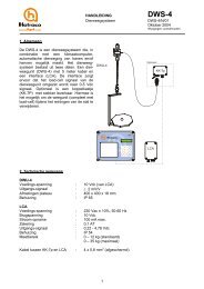
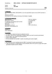
10 - Calibration of room temperature1 = roomtemperature (default)<strong>MCC</strong>-1Measure with an accurate thermometer the temperature in the neighbourhood of the sensor.After that, you enter this temperature at function number P0. Ensure that jumper A is in position‘input used for the temperature sensor’. (see figure 1)figure 111 - Option outside temperature0 = no outside temperature1 = integrated outside temperature sensorSelecting the figure 1 makes the outside temperature appear in the readout. It can becalibrated by pressing '↵' and entering the right value for the outside temperature applying the'+' and '-' keys. Insure that jumper B is in position ‘input used for the temperature sensor’. (seefigure 1)12 - Option second temperature (option board <strong>MCC</strong>-T/<strong>MCC</strong>-T2)0 = no second temperature sensor1 = yes, second temperature sensorSelecting the figure 1 makes the second temperature appear in the readout. It can becalibrated by pressing '↵' and entering the right value for the second temperature applying the'+' and '-' keys. Ensure that jumper D is in position ‘input used for the temperature sensor’.(see figure 2)figure 220 - Setting speed feedback / measuring fan (option board <strong>MCC</strong>-TTM / <strong>MCC</strong>-CV)0 = no sensor1 = sensor ventilation (speed feedback or measuring fan)Pressing '↵' produces the input status. (0 = contact open; 1 = contact closed).W/--/01/01 ENG 16
30 - (1st) Fan (1st 0-10V output or 230V output)1 = Fan<strong>MCC</strong>-1Pressing '↵' makes it possible first to set the minimum value (30 xx.L) and next to set themaximum value (30 xx.H).In case fan has a direct connection to the <strong>MCC</strong> ensure that the maximum fan voltage isabout 200 volts and the minimum fan voltage is about 80 volts.31 - 2nd 0-10V output (option print <strong>MCC</strong>-T / <strong>MCC</strong>-T2)0 = not used2 = 2nd fan3 = flap4 = diaphragm5 = heating room temperature6 = heating second temperaturePressing '↵' makes it possible first to set the minimum value (31 xx.L) and next to set themaximum value (31 xx.H).32 - 3rd 0-10V output (option print <strong>MCC</strong>-T2)0 = not used2 = 2nd fan3 = flap4 = diaphragm5 = heating room temperature6 = heating second temperaturePressing '↵' makes it possible first to set the minimum value (32 xx.L) and next to set themaximum value (32 xx.H).33 - 4th 0-10V output (option print <strong>MCC</strong>-T2)0 = not used2 = 2nd fan3 = flap4 = diaphragm5 = heating room temperature6 = heating second temperaturePressing '↵' makes it possible first to set the minimum value (33 xx.L) and next to set themaximum value (33 xx.H).40 - Setting of relay 1 function (bottem print)0 = not used2 = 2nd fan5 = heating room temperature6 = heating second temperatureHaving set a control, its output can be tested by entering 0 or 1 at 40 x.- (0 = contact open;1 = contact closed).W/--/01/01 ENG 17
41 - Setting of relay 2 function (option print <strong>MCC</strong>-T / <strong>MCC</strong>-T2)0 = not used2 = 2nd fan5 = heating room temperature6 = heating second temperature<strong>MCC</strong>-1Having set a control, its output can be tested by entering 0 or 1 at 41 x.- (0 = contactopen; 1 = contact closed).42 - Setting of relay 3 function (option print <strong>MCC</strong>-CV)0 = not used2 = 2nd fan5 = heating room temperature6 = heating second temperatureHaving set a control, its output can be tested by entering 0 or 1 at 42 x.- (0 = contactopen; 1 = contact closed)50 - Switching off ventilation at minimum0 = no switch off1 = switch off51 - Ventialation in m30 = ventilation in percentagexx.x = ventilation in 1000m 3 /hr (2.5 = 2500m 3 /hr)5 - Set pulses for ventilationPressing '↵' initiates the setting procedure.Measured number of pulses per minuteThe fan starts turning and the pilot lamp on the optionprint <strong>MCC</strong>-TTM speed feedback should blinkso rapidly that it looks as if burning without interruption. The last four digits in the read-out nowindicate the measured number of revolutions per minute. After this value has turned out to be stable(about 1 minute), press '←' once more, which stores the measured value.53 - proportion in capacity first fan : second fanthe value that can be entered indicates the proportion in capacity of the second fanwith regardto the first one.CAPACITY FIRST FAN:CAPACITY 2ND FAN1 : VALUE IN DISPLAYDefault 1 : 1.0 , means that both fans have the same capacity.Example: with a second fan having twice the capacity of the first, your entry here shouldbe 2.0.54 - Hysteresis of heating room temperature0.5 centigrades (default)W/--/01/01 ENG 18
<strong>MCC</strong>-155 - Hysteresis of heating second temperature0.5 centigrades (default)56 - Diaphragm on temperature0 = diaphragm based on ventilation1 = diaphragm based on temperature60 - Relative house sizeRatio for all sections combined. Required for central ventllation and central outlet.61 - Number central flap for ventilation0 = no central flap62 - Number central ventilation for flap0 = no central ventilation63 - Number heat demand for room heating0 = no central heating64 - Number heat demand for second heating0 = no central heatingW/--/01/01 ENG 19
<strong>MCC</strong>-1Connection diagramW/--/01/01 ENG 20
W/--/01/01 ENG 21<strong>MCC</strong>-1
<strong>MCC</strong>-1<strong>MCC</strong>-1 INSTALLATION REQUIRERMENTSAt installation of the <strong>MCC</strong>-1 be sure to observe the following :1) Preferably connect the <strong>MCC</strong>-1 to a separate circuit.2) Always fit an isolation switch.3) Fit an motor protection switch when usig one ventilator4) The <strong>MCC</strong>-1 must be provided with good earthing.5) Always use shielded cable for:- sensor inputs- 0-10V outputs- internal communication- external communication- speed feedback / measuring fan6) Seal all cable entries with silicone sealant, otherwise guarantie is void.When mounting optionprints be sure to observe the following :7) Disconnect the power before mounting the prints8) Carefully place the pins in their socket and secure print with screwsW/--/01/01 ENG 22
<strong>MCC</strong>-1<strong>MCC</strong>-1 TECHNICAL SPECIFICATIONSPower supply : 230 Vac ± 10 % , 50/60 HzInputTemperature sensors : Type PTC, 2 wire + shieldingOutside temp. sensor; -20 °C to +80 °C, ±1,0 °CRoom temp. sensor; -1 °C to +50 °C, ±0,5 °COutputsFan control : 230 Vac, triac-controlOverall fan current;4 A CE / 5 A eff. max. (<strong>MCC</strong>-1)15 A eff. max. (<strong>MCC</strong>-1Z)0,5 A minimumVentilation control : 0-10 Vdc joined to triac-controlCurrent; 1 mA maximumPower relay : Dead make-and-break contact for heating orsecond fanContact Load 6A, 250 Vac (cos φ = 1)4A, 250 Vac (cos φ = 0,4)Alarm relay : Dead break contactContact Load; 0,5 A , 24 Vac/dcHand Control100% : Fan control directly on power supplyAUTOM : Fan control governed by <strong>MCC</strong>-1ProtectionMain current : External protection 16 AControl Protection : Fuse 1 A slowEncasingDimensions (HxWxD) : 165 x 220 x 110 mmMaterial : PVC box with polycarbonate (PC) front panelProtection category : IP 54Weight : about 1,6 kgOptionprint <strong>MCC</strong>-TPower supply : by way of <strong>MCC</strong>-1InputTemperature sensor: Type PT-<strong>MCC</strong>, 2-wire + shielding2nd temp. sensor; -20 °C to +80 °C, ±1,0 °COutputsPower relay : Dead make-and-break contact for heating orsecond fanContact Load 6A, 250 Vac (cos φ = 1)4A, 250 Vac (cos φ = 0,4)0-10 Vdc Control : Proportional heating, diaphragm or flapcontrolCurrent; 1 mA maximumW/--/01/01 ENG 23
<strong>MCC</strong>-1 TECHNICAL SPECIFICATIONS CONTINUED<strong>MCC</strong>-1Optionprint <strong>MCC</strong>-T2Power supply : by way of <strong>MCC</strong>-1InputsTemperature sensor: Type PTC, 2-wire + shielding2nd temp. sensor; -20 °C to +80 °C, ±1,0 °COutputsPower relay : Dead make-and-break contact for heating orsecond fanContact Load 6A, 250 Vac (cos φ = 1)4A, 250 Vac (cos φ = 0,4)0-10 Vdc Control (3x) : Proportional heating, diaphragm or flapcontrolOptionprint <strong>MCC</strong>-TTMPower supply : by way of <strong>MCC</strong>-1Inputsspeed feedback/ : Power supply; 10 Vdc ± 10 %measuring fan Current; 25 mA maximumInput circuit for NPN-SensorInput voltage ;low level = 1 V maximaalhigh level = 3 V minimaalCount frequence; 100 puls/sec maximumOptionprint <strong>MCC</strong>-CVPower supply : by way of <strong>MCC</strong>-1NInputspeed feedback/ : Power supply; 10 Vdc ± 10 %measuring fan Current; 25 mA maximumInput circuit for NPN-SensorInput voltage ;low level = 1 V maximaalhigh level = 3 V minimaalCount frequence; 100 puls/sec maximumOutputsPower relay : Dead make-and-break contact for heatingContact Load 6A, 250 Vac (cos φ = 1)4A, 250 Vac (cos φ = 0,4)Optionprint <strong>MCC</strong>-CIPower supply : by way of <strong>MCC</strong>-1NInput/OutputInternal communication : Communication between Master and Slave(s)Interface; currentloopCurrent; 15 mABaudrate; 9600BdOption module HW-<strong>MCC</strong>Power supply : by way of <strong>MCC</strong>-1NInput/Output : Comminication-Optionprint <strong>MCC</strong>-CEExternal communication : Communication between Master and computer(possibly by modem), Interface type ; RS-232CW/--/01/01 ENG 24
<strong>MCC</strong>-1WIRING DIAGRAMS <strong>MCC</strong>-1W/--/01/01 ENG 25
<strong>MCC</strong>-1JUMPERS <strong>MCC</strong>-2At connection ensure that the jumpers are placed correctly. See for this the installation procedure.See also page 5 (jumpers bottem PCB) and page 9,10 (jumpers bottem PCB).Jumper Application PlaceJMP A Input clamps A5-A6-A7 (Roomtemperature) BottemprintJMP B Input clamps A8-A9-A10 (Outside temperature) BottemprintJMP D Input clamps D3-D4-D5 (Second temperature) Optionprint <strong>MCC</strong>-T / T2Input not usedInput used for temperature sensor6.1W/--/01/01 ENG 26
<strong>MCC</strong>-1LOW TENSIONW/--/01/01 ENG 27
<strong>MCC</strong>-1HIGH TENSIONVENTILATIONHEATINGW/--/01/01 ENG 28
OPTIONPRINT <strong>MCC</strong>-T<strong>MCC</strong>-1W/--/01/01 ENG 29
OPTIONPRINT <strong>MCC</strong>-T2<strong>MCC</strong>-1W/--/01/01 ENG 30
<strong>MCC</strong>-1OPTIONPRINT <strong>MCC</strong>-TTMW/--/01/01 ENG 31
OPTIONPRINT <strong>MCC</strong>-CV<strong>MCC</strong>-1W/--/01/01 ENG 32
OPTIONPRINT <strong>MCC</strong>-CI(Internal communication)<strong>MCC</strong>-1IMPORTANT:• connect screen only on one side to earth, cut off other side.• to avoid interference use 2 cables.• cable to use: 1 x 2 x 0,8 mm 2 screen.W/--/01/01 ENG 33
OPTIONPRINT <strong>MCC</strong>-CE(External communication)<strong>MCC</strong>-1Before mounting the optional PCB<strong>MCC</strong>-CE first remove the RAM-IC,wich will then not be needed anymore.IMPORTANT:• connect screen only on one side to earth, cut off other side.• use cable with screen. (colour code CKY-cable)W/--/01/01 ENG 34