Manual BluePRESSLine Size 1-S & Size 2-S - Walter Schulze GmbH
Manual BluePRESSLine Size 1-S & Size 2-S - Walter Schulze GmbH
Manual BluePRESSLine Size 1-S & Size 2-S - Walter Schulze GmbH
- No tags were found...

You also want an ePaper? Increase the reach of your titles
YUMPU automatically turns print PDFs into web optimized ePapers that Google loves.
Instruction <strong>Manual</strong>Version 10.01Heat press<strong>BluePRESSLine</strong><strong>Size</strong> 1-S<strong>Size</strong> 2-SVersion 10.01 1 / 19
1. Introduction1.1 Content1. Introduction 021.1 Content 021.2 Illustration of the heat press 031.3 Technical Data 031.4 Accessory 041.5 Safety arrangements of the heat press 041.6 Safety arrangements at the workspace 042. Initiation 052.1 Tips for transport 052.2 Installation of the heat press 052.3 Power supply 052.4 Initiation of the heat press 053. Working with the heat press 063.1 Programming of electronic devices 063.2 Bugfixing of the electronic devices 073.3 “Eco” Mode 073.4 Pre-pressing 073.5 Application range and sample adjustments of the heat press 073.6 Pressure adjustments 083.7 Adjustment of the electromagnet 083.8 Adjustment of the tension springs 083.9 Mounting the enlargement plate 083.10 Mounting the position laser attachment 094. Maintenance 094.1 Daily Maintenance 094.2 Monthly Maintenance 104.3 Replacing the main fuse 104.4 Replacing the electronic devices 114.5 Replacing the power supply 114.6 Replacing the fuse of the power supply 124.7 Replacing the silicon mat 124.8 Replacing the thermal fuse 124.9 Troubleshooting 134.10 Connection diagram 144.11 Testing Report 154.12 EC-Conformance declaration 155. Spare parts and illustrations 165.1 Illustration 1: Heat press 165.2 Illustration 2: Working area 175.3 Table of spare parts 18Version 10.01 2 / 19
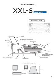
1.2 Illustration of the heat press1. Base plate2. Heating plate3. Contact pressure adjustment4. Electromagnet5. Lock plate for the electromagnet6. Pressure lever with rubber handle7. Electronic divices8. Main fuse9. Main switch10. Spiral tube1.3 Technical DataDimensions of the press:............................... 54 x 41 x 39 cmDimensions of the press:............................... 59 x 40 x 39 cmWorking plate: ......................................................... 28 x 38 cmWorkingplate ........................................................... 38 x 38 cmWeight 28 x 38 cm............................................................ 24 kgWeight 38 x 38 cm …....................................................... 25 kgOperating voltage ....................................................... 230 VACRated power 28x38 cm .................................................. 1,3 kWRated power 38x38 cm................................................... 1,7 kWMax. pressure: ............................................................... 350 kgStart up time.............................................................. ca. 15 minTemperature range.................................................. 90 - 220 °CTime settings........................................................ 1sek – 20 minEconomic Mode: ….............................................................. yesPrepressing: …..................................................................... yesVersion 10.01 3 / 19
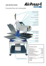
1.4 AccessoryThe heat press may be equipped with a position laser and an enlargement plate. The dimension of the enlargement plate are 48 x 68 cmor 55 x 69 cm.Instructions on how to fit the additional equipment can be found chapters 3.9 and 3.10.1.5 Safety arrangements of the heat pressThe <strong>BluePRESSLine</strong> press S is equipped with different safety arrangements, to make a safe usage possible.Main fuse 10AThe main fuse 10A is placed on the top of the heat press. In case of overcharge the main fuse prevents the heat press from gettingdamaged. Once the fuse was activated it must be replaced. The instruction for the exchange you can see in chapter 4.3.Fuse 1,6AThis fuse is placed in the 12VAC power supply in the upper part of the heat press. It saves the 12VAC circuit of an overcharge. Once thefuse was activated, it has to be replaced. The instruction for the exchange you can see in chapter 4.6.Thermal fuseThe thermal fuse is placed in the left corner on the heating plate and stops the power supply, if the temperature is exceeded too much.Acoustic signal3 Seconds before the end of the pressing process an acoustic signal will sound.Automatic switch-offIf the press doesn't get opened within 15 seconds after the pressing process, the heating element switches off automatically to avoid firehazard and overheating.1.6 Safety arrangements at the workspaceTesting the heat pressAfter a correct installation of the press it is important to ensure that the press works properly, isn't damaged and has no safety defects. Thetesting can only be done by the employer or other authorized persons and is mandatory to guarantee correct installation and safe usage ofthe press.If any irregularities regarding functionality or safety are found during the testing, these have to been noted and reported to <strong>Walter</strong> <strong>Schulze</strong><strong>GmbH</strong> in written form within 7 days. Until clarification the press can not be used.Information and EducationAccording to § 81 industrial relations law and § 14 employment protection law the employer has to make arrangements to give allinformation about the function and the range of application to the user.In particular the user needs to be acquainted with the complete manual and be explicitly informed of the dangers of working with the press.The details have to be explained in a coherent form and language.Safety distance and ventilationThe press has to be installed at a place which gives enough space on both sides to put the material on.The space in front of the press has to be wide enough to let nothing disturb the user at work.Using the press with certain materials may create a strong smell. That’s why the user should evaluate the need for a ventilation system atthe workplace.Version 10.01 4 / 19
3. Working with the heat press3.1 Programming of electronic devicesAfter switching on the press, the current temperature is shown isshown on the display and the press heats up.Change settings:1. The programming mode shows up when you press Button 1 forabout 5 seconds, until the LED1 blinks up.2. 2. LED1 blinks and the programmed temperature shows up. Theprogramming mode is activated.3. The temperature gets programmed with button 2 and 3.4. Press Button 1 shortly.On the display you now can see the programmed time. You canadjust the time by pushing Button 2 and 3.5. Press Button 1 shortly.The display shows the programmed time for pre-pressingWith the Buttons 2 or 3 you can change the pre-pressing time6. Press Button 1 shortly to save the changes and leave theprogramming mode.All settings are saved.or6. To get to the ECO programming, press Button 1 for 3 seconds.7. With Button 2 and 3 you can switch between the ECO modes:„Eco 0” - ECO Mode turned off,„Eco 1” - ECO Mode turned on, after 30 minutes temperaturedrops 50°C, then after 60 minutes the heating elements turn off.„Eco 2” - ECO Mode turned on, after 60 minutes thetemperature drops 50°C, then after 60 minutes the heatingelements turn off.„Eco 3” - ECO Mode turned on, after 120 minutes thetemperature drops 50°C, then after 60 minutes the heatingelements turn off.8. Press Button 1 shortly.With Button 2 and 3 you can select the desired sound9. To leave the programming mode press Button 1.Control of the adjusted temperatureIf you want to control which temperature is adjusted at the moment,press button 2(+). The temperature shows up on the display.TEMPERATURETIMEControl of the adjusted timeIf you want to control which time is adjusted at the moment, pressbutton 3(-). The time shows up on the display.Version 10.01 6 / 19
3.2 Bugfixing of the electronic devicesThe electronic devices of the Swing S Duo heat press control the main functions of the press.Here is a list of possible messages:ERR.1 – No connection of the electronic devices to the temperature sensor, (Temperature sensor defect/ cable not connected)ERR.2 – Connection of electronic devices and temperature sensor bypassed , (Temperature sensor defect/)ERR.3 – Resistor of temperature sensor too low. The temperature range of the electronic devices is deceeded.ERR.4 – Resistor of temperature sensor too high. The temperature range of the electronic devices exceeded.ERR.5 – No temperature rise within 3 minutes even if heating element is switched on. (Temperature fuse is defect)ERR.6 – No reduction of the temperature within 3 minutes even if heating element is turned off. (Power relay CRYDOM is defect)ERR.7 – Temperature too high, over 230°C (Power relay CRYDOM is defect)ERR.3 and ERR.4 can occur if the electronic devices are not programmed properly.3.3 “ECO” ModeThe "Eco" Mode is a special economic mode, which cools down the momentarily unused press about 50°C and turns off the heatingelements later. Both will be signaled acoustically.temperature decreasesabout -50°Cturn off the heatingelements laterECO 0 - -ECO 1 30 Minute 60 MinuteECO 2 60 Minute 60 MinuteECO 3 120Minute 60 MinuteThe press gets activated again by pushing any button at the press.3.4 Pre-pressingThe <strong>BluePRESSLine</strong> S heat press has a new function, the pre-pressing. Before closing the press, push Button 1 shortly (1 sec) to startthe pre-pressing.3.5 Application range and sample adjustments of the pressThis press is used to put transfers and transfer films on textiles. To get good results, get in contact with the producer of the textiles.Here are some settings:Film Flex 150°C – 160°C Time 15 SecondsFolie FlexS 155°C – 160°C Time 15 SecondsFolie A-Flex 155°C – 160°C Time 15 SecondsFolie Flock 160°C – 180°C Time 15 SecondsSublimation 190°C – 205°C Time 50 SecondsAll indications without warranty, please run your own testing before production.Version 10.01 7 / 19
3.6 Pressure adjustmentsThe pressure gets adjusted at the rotary knob on the upper lever. The pressure can only be changed when the heat press is opened. If thepressure is too high the heating plate could be damaged. Because you can't read the pressure on a display, you have to do tests to makesure the pressure is right.You can adjust the pressure very exactly. To do this, follow thisexplanation:1. Put a textile on the workplate.2. Close the heat press and control the pressure, after that, openthe heat press.• Turn the knop right to increase the pressure.• Turn the knop left to decrease the pressure.3.7 Adjustment of the electromagnetThe electromagnet has the function to hold down the pressure lever while pressing and to release it automatically after the preset time hasexpired. The electromagnet is adjusted at the factory and must not be changed.3.8 Adjustment of the tension springsIf you notice that heat press is not opening exactly and is too near to the base plate, you can change the adjustment of the tension springs.Put the heat press at the backside on the table. Turn the tension springs with a 17 mm wrench 2- 3 rotations to the right. After that youshould check your new adjustmentVersion 10.01 8 / 19
3.9 Mounting the enlargement plateThe enlargement plate has be mounted as it is shown in the pictures.3.10 Mounting the position laser attachmentYou have to fix the attachment with 2 screws at the heat press. Because the laser have to be in a solid position, he bolts must fixedvery tight1. Fix the attachment. 2. Fix the screws .4. Maintenance4.1 Daily MaintenanceThe working surface of the heating plate and the base plate have to be clean. The heating plate can be cleaned with a clean, dry cloth.Avoid contact with the heating plate – risk of burns. The silicon gum can be cleaned with a soft cloth. You can use mild householddetergent. Avoid scrub sponges, solvents or fuel.Version 10.01 9 / 19
4.2 Monthly MaintenanceBefore beginning maintenance work, control if the press is turned off and cold. Disconnect the press from electricity. Some movableparts need to be greased. Greasing is needed after every 200 hours of usage. You can take normal car grease which is heat resistantup to 160°C.There are 4 points on the heat press, which have to be greased after 200 hours of usage. While greasing you have to move the pressurelever up and down slowly.1. At the pressure lever, 2 little chambers (photo 1).2. At the pressure lever, 2 little chambers (photo 2).3. At the lower lever next to the base plate, 2 little chambers (photo 3).4. At the lower lever, 2 little chambers (photo 4).4.3 Replacing the main fuseIf the heat press does not work after switching on, check the main fuse of the press.The main fuse 10 A is placed at the right side of the heat press (photo 1). To exchange the fuse, switch off the heat press first andpull the plug. There are additional fuses in the manual. Then remove the fuse bracket (photo 1). Pull out the main fuse (photo 2).Replace the fuse (photo 3) and tighten the fuse bracket again (photo 4).Version 10.01 10 / 19
4.4 Replacing the electronic devicesInside the heat press are the electronic devices, which are controlling the time and the temperature. For an exchange of the electricdevices turn off the press and pull the plug. Than take off the cap in the back of the heat press (photo 1) and pull out the green connector(photo 2). Release the fixation screws (photo 3 and 4). Take out the electronic devices (photo 5). Put the green switch into the newelectronic devices and reassemble the press again.4.5 Replacing the power supplyThe press is equipped with a power supply 1,5A/12V, which supplies the electric devices with 12V tension. The power supply is placed inthe upper part of the press.To exchange the power supply, disconnect the press from the electricity first.. Remove the cover on the back of the press byloosening the 4 screws (photo 1). Pull the green plug (photo 2). Remove the power supply and insert a new one (photo 3). Tighten thecover on the back of the press againVersion 10.01 11 / 19
4.6 Replacing the fuse of the power supplyThe press is equipped with a power supply 1,5A/12V, which supplies the electric devices with 12V tension. The power supply is placed inthe upper part of the press. In the power supply is a LED. This LED can be checked throught the ventilation holes in the back of the press(photo 1).When LED glows, it is working.When LED do not glow, the fuse needs to be replaced.To exchange the fuse, disconnect the press from the electricity first. Remove the rear cover, remove the fuse bracket (photo 2) andreplace the fuse. Tighten the cover to the press again.4.7 Replacing the silicon matTo replace the silicon mat the press has to be cold and disconnected from the electricity. For the exchange you need a new silicon mat,silicon glue, acetone and a notched trowel.1. Remove the silicon mat completely with a knife .2. Clean the plate and the new silicon mat with acetone.3. Put an equal film of silicon glue on the plate using the notched trowel.4. Put on the new silicon mat.5. Close the pressure lever gently to press the silicon mat and the plate together.6. Make sure that the plate and the mat lays exactly over each other.7. Remove remaining glue or overlapping mat from the edges of the press.8. Let the glue dry for 24hours. Only then open the press.4.8 Replacing the thermal fuseFor the replacement of the thermal fuse, the heat press must be disconnected from the electricity and cold. Remove the cap from theheating plate and remove the heat isolation (photo 1). Then remove the thermal fuse (photo 2) and connect a new one (photo 3). Screwit on the base plate, set in the thermal isolation and screw on the cap.Version 10.01 12 / 19
4.9 TroubleshootingProblem Cause DebuggingGreen switch blink, but: main fuse 10 A is defect Exchange main fuse 10 Adisplay doesn´t glow If main fuse is okay, than check Exchange fuse 1,6 A in power supplyDiode in power supply glowsOr – completely exchange of power supplyplate doesn´t heatif the diode is glowing,than electronic devices are defectExchange electronic devicesThe display shows ”Err. 5” thermal fuse on heatplate is defect Exchange thermal fuseSee chapter 4.8The display shows ”Err. 1” or ”Err. 2” Temperature sensor is defect or the cable check cable to tmeperature sensorto temperature sensor is brockenor exchange temperature sensorPlease communicate with the servicetime doesn´t count down, after closing the heatpress angle at the START-button bent Bent the angle while pushing START – buttonSTART-button is defectExchange START - button if time doesn't countdown while pressing the start buttonNo acustic signal after end of pressing beeper is defect Exchange electronic devicessolid state relay CRYDOM is defectexchange solid state relays CRYDOMThe display shows ”Err. 6”Please communicate with the serviceButton doesn´t work setting buttons are defect exchange setting buttonsno settings possible in temperature and timereal temperature doesn´t match with temperature breakdown of electronic devices reset electronic devicesShown on the display – temperature too high/lowVersion 10.01 13 / 19
4.10 Connection diagramVersion 10.01 14 / 19
4.11 Testing reportFinal check of the heat press:o - base, painto - greasing of the waveso - heating plate and baseplate, silicon, teflono - electronic connection, safety wire, power cableo - electronic, max. temperature 220°Coooooo- check of all functions- working time at 180°C . . . . . . . hours- temperature tolernace at 180°C . . . . . . -/ . . . . . .+°C- working time at 220°C . . . . . . . .hours- test with a transfer film- caution labelsSerial number . . . . . . . . . . . . . . . . . . Date . . . . . . . . . . . . . . . . . . . . Signature . . . . . . . . . . . . . . . . . . . . . . . . . . .4.12 EC-Conformance-Declaration after EC- guideline for machines 2006/46 ECThe <strong>Walter</strong> <strong>Schulze</strong> <strong>GmbH</strong>Schmalenbachstraße 1512057 Berlinas European representative of the manufacturer company ROMANIK hereby declares that the following machine:Heat press . . . . . . . . . . . . . . . Serial number . . . . . . . . . . . .is compliant with the specifications of the following EC directives:Machinery ( 2006/46)Low Voltage (2006/95)EMC (2004/108)used norms and technical specifications:EN 292-1 EN 292-2 safety of machinesEN 60204-1 electrical equipment of machinesBerlin , . . . . . . ._____________________________Peter MeidingerPresidentAll SCHULZE heat presses are exempt from the waste disposal law under reg. no. DE 231060054.Version 10.01 15 / 19
5. Spare parts and illustrations5.1 Illustration 1: Heat pressVersion 10.01 16 / 19
5.2 Illustration 2: Working areaVersion 10.01 17 / 19
5.3 Table spare partsSymbol58.00158.002 CoverScrew M4 x 1258.00358.00458.00558.00658.00758.00858.00958.01058.01158.01258.013 Handle58.014 Covering spa58.015 Connection piece58.016 Electromagnet plate58.01758.01858.01958.02058.021 Allen M 558.02258.02358.02458.02558.02658.02758.02958.030 Electromagnet58.03158.03258.03358.034 Spring R-3058.035 Chassis58.03658.03758.03858.03958.04058.04158.04258.04358.04458.045Screw M4 x 30Cable gland M16 x 1,5Allen screw M5 x 15HousingButton Rafi GrünFuse bracketMain switchConnection piece PG 11Pressure leverGrommet Ø 10Bolt Ø 10 x 130Bolt Ø 10 x 94Power supplyRotary handle Ø 50 BonexRubber footScrew M 6 x 15Pressure lever 2Pressure adjustment screwFastening of the heatingplateGrommet Ø 12Threaded nut M 12Threaded nut M 6Electronic devicesThreaded nut M 10Bolt Ø 12 x 145Bolt Ø 17 x 2,4 x 26Plastic cap Ø 35Silicon mat 23 x 38Heating plateCountersink screw M 4 x 35Screw M 5 x 15Thermo coupleThermal fuseAluminium plate with heating elementDescriptionVersion 10.01 18 / 19
Symbol58.04658.04758.048 Spiral tube58.049 Spring S-0158.05058.05158.05258.053 Bushing58.054 Axle Ø 2Threaded nut M 10Teflon cloth58.05958.06058.06158.06258.06358.064 CRYDOMScrew M4 x 10Triangular coverCover of the heating plate 28 x 3858.05558.056Teflon fasteningTeflon58.057 Axle Ø 258.058 Spring S-04Countersink screw M 4 x 30Threaded nut M 4FilterGrommet Ø 8Threaded nut M 8DescriptionVersion 10.01 19 / 19