to download the Shinko ACS-13A manual in PDF format
to download the Shinko ACS-13A manual in PDF format
to download the Shinko ACS-13A manual in PDF format

You also want an ePaper? Increase the reach of your titles
YUMPU automatically turns print PDFs into web optimized ePapers that Google loves.
INSTRUCTION MANUALMicro-computer based Digital Indicat<strong>in</strong>g Controller<strong>ACS</strong>-<strong>13A</strong>No.<strong>ACS</strong>12E2 2005.08PrefaceThank you for purchas<strong>in</strong>g of our microcomputer based temperature <strong>in</strong>dicat<strong>in</strong>g controller <strong>ACS</strong>-<strong>13A</strong>.This <strong>manual</strong> conta<strong>in</strong>s <strong>in</strong>structions for <strong>the</strong> mount<strong>in</strong>g, functions, operations and notes when operat<strong>in</strong>g <strong>the</strong> <strong>ACS</strong>-<strong>13A</strong>.To prevent accidents aris<strong>in</strong>g from <strong>the</strong> misuse of this controller, please ensure <strong>the</strong> opera<strong>to</strong>r receives this <strong>manual</strong>.Characters used <strong>in</strong> this <strong>manual</strong>:Number, / -1 0 1 2 3 4 5 6 7 8 9IndicationAlphabet A B C D E F G H I J K L MIndicationAlphabet N O P Q R S T U V W X Y ZIndicationNotes• This <strong>in</strong>strument should be used <strong>in</strong> accordance with <strong>the</strong> specifications described <strong>in</strong> <strong>the</strong> <strong>manual</strong>.If it is not used accord<strong>in</strong>g <strong>to</strong> <strong>the</strong> specifications, it may malfunction or cause fire.• Be sure <strong>to</strong> follow <strong>the</strong> warn<strong>in</strong>gs, cautions and notices. If <strong>the</strong>y are not observed, serious <strong>in</strong>jury or malfunction may occur.• The contents of this <strong>in</strong>struction <strong>manual</strong> are subject <strong>to</strong> change without notice.• Care has been taken <strong>to</strong> assure that <strong>the</strong> contents of this <strong>in</strong>struction <strong>manual</strong> are correct, but if <strong>the</strong>re are any doubts,mistakes or questions, please <strong>in</strong>form our sales department.• This <strong>in</strong>strument is designed <strong>to</strong> be <strong>in</strong>stalled with<strong>in</strong> a control panel. If it is not, measures must be taken <strong>to</strong> ensure that<strong>the</strong> opera<strong>to</strong>r cannot <strong>to</strong>uch power term<strong>in</strong>als or o<strong>the</strong>r high voltage sections.• Any unauthorized transfer or copy<strong>in</strong>g of this document, <strong>in</strong> part or <strong>in</strong> whole, is prohibited.• <strong>Sh<strong>in</strong>ko</strong> Technos CO., LTD. is not liable for any damages or secondary damages <strong>in</strong>curred as a result of us<strong>in</strong>g thisproduct, <strong>in</strong>clud<strong>in</strong>g any <strong>in</strong>direct damages.Safety precautions (Be sure <strong>to</strong> read <strong>the</strong>se precautions before us<strong>in</strong>g our products.)The safety precautions are classified <strong>in</strong><strong>to</strong> categories: “Warn<strong>in</strong>g” and “Caution”. Depend<strong>in</strong>g on circumstances, procedures<strong>in</strong>dicated by Caution may be l<strong>in</strong>ked <strong>to</strong> serious results, so be sure <strong>to</strong> follow <strong>the</strong> directions for usage.Warn<strong>in</strong>gCautionProcedures which may lead <strong>to</strong> dangerous conditions and cause death or serious<strong>in</strong>jury, if not carried out properly.Procedures which may lead <strong>to</strong> dangerous conditions and cause superficial <strong>to</strong> medium<strong>in</strong>jury or physical damage or may degrade or damage <strong>the</strong> product, if not carried outproperly.Warn<strong>in</strong>g• To prevent an electric shock or fire, only <strong>Sh<strong>in</strong>ko</strong> or qualified service personnel may handle <strong>the</strong> <strong>in</strong>ner assembly.• To prevent an electric shock, fire or damage <strong>to</strong> <strong>the</strong> <strong>in</strong>strument, parts replacement may only be undertakenby <strong>Sh<strong>in</strong>ko</strong> or qualified service personnel.Safety precautions• To ensure safe and correct use, thoroughly read and understand this <strong>manual</strong> before us<strong>in</strong>g this <strong>in</strong>strument.• This <strong>in</strong>strument is <strong>in</strong>tended <strong>to</strong> be used for <strong>in</strong>dustrial mach<strong>in</strong>ery, mach<strong>in</strong>e <strong>to</strong>ols and measur<strong>in</strong>g equipment. Verifycorrect usage after consult<strong>in</strong>g <strong>the</strong> purpose of use with our agency or ma<strong>in</strong> office. (Never use this <strong>in</strong>strument formedical purposes with which human lives are <strong>in</strong>volved.)• External protection devices such as protection equipment aga<strong>in</strong>st excessive temperature rise, etc. must be <strong>in</strong>stalled,as malfunction of this product could result <strong>in</strong> serious damage <strong>to</strong> <strong>the</strong> system or <strong>in</strong>jury <strong>to</strong> personnel. Also properperiodic ma<strong>in</strong>tenance is required.• This <strong>in</strong>strument must be used under <strong>the</strong> conditions and environment described <strong>in</strong> this <strong>manual</strong>. <strong>Sh<strong>in</strong>ko</strong> Technos Co.,Ltd. does not accept liability for any <strong>in</strong>jury, loss of life or damage occurr<strong>in</strong>g due <strong>to</strong> <strong>the</strong> <strong>in</strong>strument be<strong>in</strong>g used underconditions not o<strong>the</strong>rwise stated <strong>in</strong> this <strong>manual</strong>.Caution with respect <strong>to</strong> Export Trade Control Ord<strong>in</strong>anceTo avoid this <strong>in</strong>strument from be<strong>in</strong>g used as a component <strong>in</strong>, or as be<strong>in</strong>g utilized <strong>in</strong> <strong>the</strong> manufacture of weaponsof mass destruction (i.e. military applications, military equipment, etc.), please <strong>in</strong>vestigate <strong>the</strong> end users and <strong>the</strong>f<strong>in</strong>al use of this <strong>in</strong>strument. In <strong>the</strong> case of resale, ensure that this <strong>in</strong>strument is not illegally exported.1
1. Installation precautionsCautionThis <strong>in</strong>strument is <strong>in</strong>tended <strong>to</strong> be used under <strong>the</strong> follow<strong>in</strong>g environmental conditions(IEC61010-1): Overvoltage category , Pollution degree 2Ensure <strong>the</strong> mount<strong>in</strong>g location corresponds <strong>to</strong> <strong>the</strong> follow<strong>in</strong>g conditions:• A m<strong>in</strong>imum of dust, and an absence of corrosive gases• No flammable, explosive gases• No mechanical vibrations or shocks• No exposure <strong>to</strong> direct sunlight, an ambient temperature of 0 <strong>to</strong> 50 (32 <strong>to</strong> 122 ) that does notchange suddenly• An ambient non-condens<strong>in</strong>g humidity of 35 <strong>to</strong> 85%RH• No large capacity electromagnetic switches or cables through which large current is flow<strong>in</strong>g.• No water, oil or chemicals or where <strong>the</strong> vapors of <strong>the</strong>se substances can come <strong>in</strong><strong>to</strong> directcontact with <strong>the</strong> unitNote • Do not <strong>in</strong>stall this <strong>in</strong>strument near flammable material even though <strong>the</strong> case of this <strong>in</strong>strumentis made of flame resistant res<strong>in</strong>.Avoid sett<strong>in</strong>g this <strong>in</strong>strument directly on flammable material.2. Wir<strong>in</strong>g precautionsCaution• Do not leave bits of wire <strong>in</strong> <strong>the</strong> <strong>in</strong>strument, because <strong>the</strong>y could cause fire or malfunction.• Use <strong>the</strong> solderless term<strong>in</strong>al with an <strong>in</strong>sulation sleeve <strong>in</strong> which <strong>the</strong> M3 screw fits when wir<strong>in</strong>g <strong>the</strong><strong>ACS</strong>-<strong>13A</strong>.• The term<strong>in</strong>al block of this <strong>in</strong>strument is designed <strong>to</strong> be wired from <strong>the</strong> left side. The lead wiremust be <strong>in</strong>serted from <strong>the</strong> left side of <strong>the</strong> term<strong>in</strong>al, and fastened with <strong>the</strong> term<strong>in</strong>al screw.• Tighten <strong>the</strong> term<strong>in</strong>al screw <strong>to</strong> with<strong>in</strong> <strong>the</strong> specified <strong>to</strong>rque. If excessive force is applied <strong>to</strong> <strong>the</strong>screw when tighten<strong>in</strong>g, <strong>the</strong> term<strong>in</strong>al screw or case may be damaged.• When us<strong>in</strong>g a term<strong>in</strong>al cover, pass term<strong>in</strong>al wires numbered 7 <strong>to</strong> 12 <strong>in</strong><strong>to</strong> <strong>the</strong> holes of <strong>the</strong> term<strong>in</strong>alcover.• This <strong>in</strong>strument does not have a built-<strong>in</strong> power switch, circuit breaker or fuse.It is necessary <strong>to</strong> <strong>in</strong>stall <strong>the</strong>m near <strong>the</strong> controller.(Recommended fuse: Time-lag fuse, rated voltage 250V AC, rated current 2A)• For a 24V AC/DC power source, do not confuse polarity when us<strong>in</strong>g direct current (DC).• Do not apply a commercial power source <strong>to</strong> <strong>the</strong> sensor which is connected <strong>to</strong> <strong>the</strong> <strong>in</strong>put term<strong>in</strong>alnor allow <strong>the</strong> power source <strong>to</strong> come <strong>in</strong><strong>to</strong> contact with <strong>the</strong> sensor.• Use a <strong>the</strong>rmocouple and compensat<strong>in</strong>g lead wire accord<strong>in</strong>g <strong>to</strong> <strong>the</strong> sensor <strong>in</strong>put specificationsof this controller.• Use <strong>the</strong> 3-wire RTD accord<strong>in</strong>g <strong>to</strong> <strong>the</strong> sensor <strong>in</strong>put specifications of this controller.• (+) side <strong>in</strong>put term<strong>in</strong>al number of 0 <strong>to</strong> 5V DC, 1 <strong>to</strong> 5V DC, 0 <strong>to</strong> 10V DC differs from that of 0 <strong>to</strong> 1V DC.(+) side <strong>in</strong>put term<strong>in</strong>al number of 0 <strong>to</strong> 5V DC, 1 <strong>to</strong> 5V DC, 0 <strong>to</strong> 10V DC: 9(+) side <strong>in</strong>put term<strong>in</strong>al number of 0 <strong>to</strong> 1V DC: 10• When us<strong>in</strong>g a relay contact output type, use a relay accord<strong>in</strong>g <strong>to</strong> <strong>the</strong> capacity of <strong>the</strong> load <strong>to</strong>protect <strong>the</strong> built-<strong>in</strong> relay contact.• When wir<strong>in</strong>g, keep <strong>in</strong>put wires (<strong>the</strong>rmocouple, RTD, etc.) away from AC sources or load wires <strong>to</strong>avoid external <strong>in</strong>terference.3. Operation and ma<strong>in</strong>tenance precautionsCaution• It is recommended that PID au<strong>to</strong>-tun<strong>in</strong>g be performed on <strong>the</strong> trial run.• Do not <strong>to</strong>uch live term<strong>in</strong>als. This may cause electric shock or problems <strong>in</strong> operation.• Turn <strong>the</strong> power supplied <strong>to</strong> <strong>the</strong> <strong>in</strong>strunment OFF when retighten<strong>in</strong>g <strong>the</strong> term<strong>in</strong>al or clean<strong>in</strong>g.Work<strong>in</strong>g or <strong>to</strong>uch<strong>in</strong>g <strong>the</strong> term<strong>in</strong>al with <strong>the</strong> power switched ON may result <strong>in</strong> severe <strong>in</strong>jury ordeath due <strong>to</strong> Electric Shock.• Use a soft, dry cloth when clean<strong>in</strong>g <strong>the</strong> <strong>in</strong>strument.(Alcohol based substances may tarnish or deface <strong>the</strong> unit.)• As <strong>the</strong> display section is vulnerable, do not strike or scratch it with a hard object or press hard on it.2
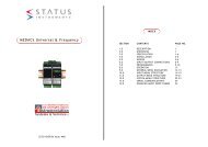
1. Model1.1 Model<strong>ACS</strong> – 1 3 , Series name: <strong>ACS</strong>-<strong>13A</strong> (W48 x H48 x D62mm)Control action 3 PIDA1 A Alarm type can be selected by keypad. *1RRelay contact: 1aControl output, Heat<strong>in</strong>gS Non-contact voltage (for SSR drive): 12V DCoutput: O1 (OUT1)ADC current: 4 <strong>to</strong> 20mA DC15%Input M Multi-range *2Supply voltage100 <strong>to</strong> 240V AC (standard)1 24V AC/DC *3A2 Alarm 2 output (A2) *1W(20A)CT rated current: 20A (S<strong>in</strong>gle phase)HeaterOptionW(50A)CT rated current: 50A (S<strong>in</strong>gle phase)burnout(Multiple options are selectable.W3(20A)alarmCT rated current: 20A (3-phase)W3(50A)CT rated current: 50A (3-phase)See pages 22, 23 for optionDR, DSHeat<strong>in</strong>g/Cool<strong>in</strong>g control Relay contact: 1acomb<strong>in</strong>ations.)Cool<strong>in</strong>g output: O2 (OUT2) Non-contact voltage: 12V DC 15%C5 Serial communication (RS-485)SM Set value memory external selection*1: Alarm types (9 types and No alarm action) and Energized/Deenergized can be selected by keypad.*2: Thermocouple, RTD, DC current and DC voltage can be selected by keypad.For DC current <strong>in</strong>put, connect 50 shunt resis<strong>to</strong>r (sold separately) externally.*3: Supply voltage 100 <strong>to</strong> 240V AC is standard. When order<strong>in</strong>g 24V AC/DC, enter “1” after <strong>the</strong> <strong>in</strong>put code.1.2 How <strong>to</strong> read <strong>the</strong> model label(1) The model labels are attached <strong>to</strong> <strong>the</strong> left side of <strong>the</strong> case and <strong>in</strong>ner assembly.For Heater burnout alarm output, CT rated current is written <strong>in</strong> <strong>the</strong> bracket.(2) (1): Model name, Power supply (For 24V AC/DC, “1” is entered), Options(2): Serial number (Only on <strong>in</strong>ner assembly)(e.g.) Relay contact output/Multi-range <strong>in</strong>put2. Name and functions of <strong>the</strong> sections(1)(2)(3)(4)(5)(6)(7)(8)(12)(1) PV <strong>in</strong>dica<strong>to</strong>r : Lights when PV is <strong>in</strong>dicated <strong>in</strong> <strong>the</strong> PV/SV display mode.(2) PV display : Indicates <strong>the</strong> PV (process variable).(11) (3) SV <strong>in</strong>dica<strong>to</strong>r : Lights when SV is <strong>in</strong>dicated <strong>in</strong> <strong>the</strong> PV/SV display mode.(4) MEMO <strong>in</strong>dica<strong>to</strong>r : Lights when Set value memory externalselection (SM option) is added.(5) MEMO display : Indicates <strong>the</strong> set value memory number.(6) SV display : Indicates <strong>the</strong> SV (set value).(10) (7) Increase key : Increases <strong>the</strong> numeric value.(8) Decrease key : Decreases <strong>the</strong> numeric value.(9) (9) Mode key : Selects <strong>the</strong> sett<strong>in</strong>g mode, or registers <strong>the</strong> set value.To register <strong>the</strong> set (selected) value, press this key.(10) OUT/OFF key: Switches control output ON/OFF or Au<strong>to</strong>/Manual control.To release <strong>the</strong> control output ON/OFF, press this key for approx. 1sec.(11) Action <strong>in</strong>dica<strong>to</strong>rsO1 (OUT1): Lights when control output is ON or when Heat<strong>in</strong>g output(D option) is ON. For DC current output type, flashescorrespond<strong>in</strong>g <strong>to</strong> <strong>the</strong> MV <strong>in</strong> 0.25 second cycles.O2 (OUT2): Lights when cool<strong>in</strong>g output (D option) is ON.EV1: Lights when Alarm 1 output is ON.EV2: Lights when Alarm 2 output (A2 option) is ON or when Heaterburnout alarm (W, W3 option) is ON.AT : Flashes while AT (au<strong>to</strong>-tun<strong>in</strong>g) or au<strong>to</strong>-reset is perform<strong>in</strong>g.T/R : Lights dur<strong>in</strong>g Serial communication (C5 option) (TX output).LOCK: Lights when Lock 1, Lock 2 or Lock 3 is selected.(12) Console connec<strong>to</strong>r: By connect<strong>in</strong>g <strong>to</strong> <strong>the</strong> USB communication cable (CMA, sold separately), <strong>the</strong>follow<strong>in</strong>g operations can be conducted from <strong>the</strong> external computer us<strong>in</strong>g <strong>the</strong> Console softwareSWS-<strong>ACS</strong>01M. (1) Read<strong>in</strong>g and sett<strong>in</strong>g of SV, PID and various set values, (2) Read<strong>in</strong>g of PV andaction status, (3) Function change3
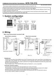
3. Mount<strong>in</strong>g <strong>to</strong> <strong>the</strong> control panel3.1 External dimensions (Unit: mm)Gasket Mount<strong>in</strong>g frame Term<strong>in</strong>al cover (sold separately) (*)(*) When TC option is added3.2 Panel cu<strong>to</strong>ut (Unit: mm)(Fig. 3.1-1)7545 +0.5045 +0.50n x 48-3 +0.50(Fig. 3.2-1)3.3 CT (Current transformer) external dimensions (Unit: mm)CTL-6S (for 20A) CTL-12-S36-10L1 (for 50A)45 +0.50Lateral close mount<strong>in</strong>gn: Number of units mountedCaution: If lateral close mount<strong>in</strong>g is used for <strong>the</strong> controller,IP66 specification (Dust-proof/Drip-proof) may becompromised, and all warranties will be <strong>in</strong>validated.(Fig. 3.3-1)3.4 Mount<strong>in</strong>g and removal <strong>to</strong>/from <strong>the</strong> control panelCautionAs <strong>the</strong> mount<strong>in</strong>g frame is made of res<strong>in</strong>, do not use excessive force while tighten<strong>in</strong>gscrews, or <strong>the</strong> mount<strong>in</strong>g frame could be damaged. Tighten screws with one rotation upon<strong>the</strong> screw tips <strong>to</strong>uch<strong>in</strong>g <strong>the</strong> panel. The <strong>to</strong>rque is approximately 0.05 <strong>to</strong> 0.06 N•m.How <strong>to</strong> mount <strong>the</strong> <strong>ACS</strong>-<strong>13A</strong>Mount <strong>the</strong> controller vertically <strong>to</strong> <strong>the</strong> flat, rigid panel <strong>to</strong> ensure it adheres <strong>to</strong> <strong>the</strong> Dust-proof/Drip-proof specification (IP66).Mountable panel thickness: With<strong>in</strong> 1 <strong>to</strong> 5mm(1) Insert <strong>the</strong> controller from <strong>the</strong> front side of <strong>the</strong> panel. (Fig.3.4-1)(2) Insert <strong>the</strong> unit until mount<strong>in</strong>g frame comes <strong>in</strong><strong>to</strong> contact with <strong>the</strong> panel, and fasten with <strong>the</strong> screw.Tighten screws with one rotation upon <strong>the</strong> screw tips <strong>to</strong>uch<strong>in</strong>g <strong>the</strong> panel. (Fig.3.4-2)The <strong>to</strong>rque is approximately 0.05 <strong>to</strong> 0.06N•m.How <strong>to</strong> remove <strong>the</strong> mount<strong>in</strong>g frame (Fig. 3.4-3)(1) Turn <strong>the</strong> power <strong>to</strong> <strong>the</strong> unit OFF, and disconnect all wires before remov<strong>in</strong>g <strong>the</strong> mount<strong>in</strong>g frame.(2) Insert a flat blade screwdriver between <strong>the</strong> screw frame and unit 1 .(3) Slowly push <strong>the</strong> frame upward us<strong>in</strong>g <strong>the</strong> screwdriver 2 , while push<strong>in</strong>g <strong>the</strong> unit <strong>to</strong>ward <strong>the</strong> panel 3 .(4) Repeat step (2) and slowly push <strong>the</strong> frame downward us<strong>in</strong>g <strong>the</strong> screwdriver for <strong>the</strong> o<strong>the</strong>r side.The frame can be removed little by little by repeat<strong>in</strong>g <strong>the</strong>se steps.4
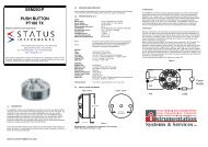
GasketMount<strong>in</strong>g frame(Fig.3.4-1)4. Wir<strong>in</strong>gWarn<strong>in</strong>gTurn <strong>the</strong> power supply <strong>to</strong> <strong>the</strong> <strong>in</strong>strument off before wir<strong>in</strong>g or check<strong>in</strong>g.Work<strong>in</strong>g or <strong>to</strong>uch<strong>in</strong>g <strong>the</strong> term<strong>in</strong>al with <strong>the</strong> power switched on may result <strong>in</strong> severe <strong>in</strong>juryor death due <strong>to</strong> Electric Shock.Lead wire solderless term<strong>in</strong>alUse a solderless term<strong>in</strong>al with an <strong>in</strong>sulation sleeve <strong>in</strong> which an M3 screwfits as shown below. The <strong>to</strong>rque is approximately 0.6N•m <strong>to</strong> 1.0N•m.Solderlessterm<strong>in</strong>alManufacturer Model name Tighten<strong>in</strong>g<strong>to</strong>rqueNichifu Term<strong>in</strong>al Industries CO.,LTD. 1.25Y-3Y type0.6N•mJapan Solderless Term<strong>in</strong>al MFG CO.,LTD. VD1.25-B3A Max.Round Nichifu Term<strong>in</strong>al Industries CO.,LTD. 1.25-3 1.0N•mtype Japan Solderless Term<strong>in</strong>al MFG CO.,LTD. V1.25-35.8mm or less(Fig. 4-1)ø 3.2mm5.8mm or less(Fig.3.4-2)(Fig.3.4-3)• EV1 : Alarm 1 output• O2/EV2: Cool<strong>in</strong>g output (D option), Alarm 2output (A2 option) or Heater burnoutalarm output (W, W3 option)• O1 : Control output or Heat<strong>in</strong>g output (Doption)• DC : DC current, DC voltage <strong>in</strong>put (For DCvoltage <strong>in</strong>put, + side term<strong>in</strong>al numberdiffers depend<strong>in</strong>g on <strong>the</strong> voltage <strong>in</strong>put.)• TC : Thermocouple <strong>in</strong>put• RTD : Resistance temperature detec<strong>to</strong>r <strong>in</strong>put• CT1 : CT <strong>in</strong>put 1 (W, W3 option)• CT2 : CT <strong>in</strong>put 2 (W3 option)• DI : Contact <strong>in</strong>put (SM option)• RS-485 : Serial communication RS-485 (C5 option)When us<strong>in</strong>g a term<strong>in</strong>al coverWhen us<strong>in</strong>g a term<strong>in</strong>al cover(TC option), pass term<strong>in</strong>al wiresnumbered 7 <strong>to</strong> 12 <strong>in</strong><strong>to</strong> <strong>the</strong> holesof <strong>the</strong> term<strong>in</strong>al cover.3.2mmTerm<strong>in</strong>al cover(Fig. 4-2)(Fig. 4-3)Heater burnout alarm (W, W3 option)This alarm is not usable for detect<strong>in</strong>g heater current under phase control.Use <strong>the</strong> CT (current transformer) provided, and pass one lead wire of <strong>the</strong> heater circuit <strong>in</strong><strong>to</strong> <strong>the</strong> holeof <strong>the</strong> CT. (Fig. 4-4). When wir<strong>in</strong>g, keep <strong>the</strong> CT wire away from AC sources or load wires <strong>to</strong> avoid <strong>the</strong>external <strong>in</strong>terference.In <strong>the</strong> case of 3-phase (W3 option), pass any 2 lead wires of R, S, T <strong>in</strong><strong>to</strong> <strong>the</strong> CT, and connect <strong>the</strong>m withCT1 (13, 14) and CT2 term<strong>in</strong>als (14, 15). (Fig.4-5)(13)CT1 <strong>in</strong>put Term<strong>in</strong>als(14)PowerRsupplyCTPass any 2 wires of R, S and T <strong>in</strong><strong>to</strong> CT.ST(Fig. 4-4) (Fig. 4-5)Heater5
6. SetupSetup should occur before us<strong>in</strong>g this controller, <strong>to</strong> set <strong>the</strong> Input type, Alarm action, Control action, etc.accord<strong>in</strong>g <strong>to</strong> <strong>the</strong> users’ conditions.Default values: Input (K, -200 <strong>to</strong>1370 ), Alarm 1 (No alarm action), Reverse (Heat<strong>in</strong>g) actionIf <strong>the</strong> users’ specification is <strong>the</strong> same as <strong>the</strong> default value of <strong>the</strong> <strong>ACS</strong>-<strong>13A</strong>, it is not necessary <strong>to</strong> set up <strong>the</strong>controller. Proceed <strong>to</strong> Chapter “7. Sett<strong>in</strong>gs”.Turn <strong>the</strong> power supply <strong>to</strong> <strong>the</strong> <strong>ACS</strong>-<strong>13A</strong> ON.After <strong>the</strong> power is turned on, <strong>the</strong> PV display <strong>in</strong>dicates <strong>the</strong> <strong>in</strong>put type, and <strong>the</strong> SV display <strong>in</strong>dicates <strong>the</strong><strong>in</strong>put range high limit value (<strong>the</strong>rmocouple, RTD <strong>in</strong>put) or scal<strong>in</strong>g high limit value (DC <strong>in</strong>put) forapproximately 3 seconds. (Table 6-1)Dur<strong>in</strong>g this time, all outputs and <strong>the</strong> <strong>in</strong>dica<strong>to</strong>rs are <strong>in</strong> OFF status.Control will <strong>the</strong>n start and <strong>the</strong> PV display <strong>in</strong>dicates PV (process variable) and <strong>the</strong> SV display<strong>in</strong>dicates SV (set value). While control output OFF function is work<strong>in</strong>g, <strong>the</strong> PV display <strong>in</strong>dicates .(Indication depends on <strong>the</strong> selection dur<strong>in</strong>g “Output status selection when <strong>in</strong>put abnormal”.)(Table 6-1)KSensor <strong>in</strong>putJRSBETNPL-C (W/Re5-26)Pt100JPt100PV display SV display PV display SV display4 <strong>to</strong> 20mA DC0 <strong>to</strong> 20mA DC0 <strong>to</strong> 1V DC0 <strong>to</strong> 5V DC1 <strong>to</strong> 5V DC0 <strong>to</strong> 10V DCScal<strong>in</strong>g high limit valueBasic operation of sett<strong>in</strong>gsTo enter each sett<strong>in</strong>g mode, refer <strong>to</strong> respective sett<strong>in</strong>g modes.To set or select each sett<strong>in</strong>g item, use <strong>the</strong> or key, <strong>the</strong>n register <strong>the</strong> value with <strong>the</strong> key.6.1 Setup modeTo enter <strong>the</strong> Setup mode, press <strong>the</strong> key for approx. 3 seconds while hold<strong>in</strong>g down <strong>the</strong> key <strong>in</strong> <strong>the</strong>PV/SV display mode.Character Name, Function, Sett<strong>in</strong>g range Default valueInput type selection K (-200 <strong>to</strong> 1370 )• The <strong>in</strong>put type can be selected from <strong>the</strong>rmocouple (10 types), RTD (2 types), DCcurrent (2 types) and DC voltage (4 types), and <strong>the</strong> unit / can be selected as well.• When chang<strong>in</strong>g <strong>the</strong> <strong>in</strong>put from DC voltage <strong>to</strong> o<strong>the</strong>r <strong>in</strong>puts, remove <strong>the</strong> sensor connected<strong>to</strong> this controller first, <strong>the</strong>n change for <strong>the</strong> <strong>in</strong>put. If <strong>the</strong> <strong>in</strong>put is changed with <strong>the</strong> sensorconnected, <strong>the</strong> <strong>in</strong>put circuit may break.• (+) side <strong>in</strong>put term<strong>in</strong>al number of 0 <strong>to</strong> 5V DC, 1 <strong>to</strong> 5V DC, 0 <strong>to</strong> 10V DC differs fromthat of 0 <strong>to</strong> 1V DC.(+) side <strong>in</strong>put term<strong>in</strong>al number of 0 <strong>to</strong> 5V DC, 1 <strong>to</strong> 5V DC, 0 <strong>to</strong> 10V DC: 9(+) side <strong>in</strong>put term<strong>in</strong>al number of 0 <strong>to</strong> 1V DC: 10K -200 <strong>to</strong> 1370 K -320 <strong>to</strong> 2500K -200.0 <strong>to</strong> 400.0 K -320.0 <strong>to</strong> 750.0J -200 <strong>to</strong> 1000 J -320 <strong>to</strong> 1800R 0 <strong>to</strong> 1760 R 0 <strong>to</strong> 3200S 0 <strong>to</strong> 1760 S 0 <strong>to</strong> 3200B 0 <strong>to</strong> 1820 B 0 <strong>to</strong> 33007
E -200 <strong>to</strong> 800 E -320 <strong>to</strong> 1500T -200.0 <strong>to</strong> 400.0 T -320.0 <strong>to</strong> 750.0N -200 <strong>to</strong> 1300 N -320 <strong>to</strong> 2300PL- 0 <strong>to</strong> 1390 PL- 0 <strong>to</strong> 2500C(W/Re5-26) 0 <strong>to</strong> 2315 C(W/Re5-26) 0 <strong>to</strong> 4200Pt100 -200.0 <strong>to</strong> 850.0 Pt100 -320.0 <strong>to</strong> 1500.0JPt100 -200.0 <strong>to</strong> 500.0 JPt100 -320.0 <strong>to</strong> 900.0Pt100 -200 <strong>to</strong> 850 Pt100 -320 <strong>to</strong> 1500JPt100 -200 <strong>to</strong> 500 JPt100 -320 <strong>to</strong> 9004 <strong>to</strong> 20mA DC -2000 <strong>to</strong> 100000 <strong>to</strong> 20mA DC -2000 <strong>to</strong> 100000 <strong>to</strong> 1V DC -2000 <strong>to</strong> 100000 <strong>to</strong> 5V DC -2000 <strong>to</strong> 100001 <strong>to</strong> 5V DC -2000 <strong>to</strong> 100000 <strong>to</strong> 10V DC -2000 <strong>to</strong> 10000Scal<strong>in</strong>g high limit sett<strong>in</strong>g 1370• Sets scal<strong>in</strong>g high limit value.• Sett<strong>in</strong>g range: Scal<strong>in</strong>g low limit value <strong>to</strong> <strong>in</strong>put range high limit valueDC voltage, current <strong>in</strong>put: -2000 <strong>to</strong> 10000 (The placement of <strong>the</strong> decimal po<strong>in</strong>t follows <strong>the</strong> selection.)Scal<strong>in</strong>g low limit sett<strong>in</strong>g -200• Sets scal<strong>in</strong>g low limit value.• Sett<strong>in</strong>g range: Input range low limit value <strong>to</strong> scal<strong>in</strong>g high limit valueDC voltage, current <strong>in</strong>put: -2000 <strong>to</strong> 10000 (The placement of <strong>the</strong> decimal po<strong>in</strong>t follows <strong>the</strong> selection.)Decimal po<strong>in</strong>t place selectionNo decimal po<strong>in</strong>t• Selects decimal po<strong>in</strong>t place.Available only for DC <strong>in</strong>puts• : No decimal po<strong>in</strong>t : 1 digit after decimal po<strong>in</strong>t: 2 digits after decimal po<strong>in</strong>t : 3 digits after decimal po<strong>in</strong>tPV filter time constant sett<strong>in</strong>g0.0 seconds• Sets PV filter time constant.If <strong>the</strong> value is set <strong>to</strong>o large, it affects control result due <strong>to</strong> <strong>the</strong> delay of response.• Sett<strong>in</strong>g range: 0.0 <strong>to</strong> 10.0 secondsOUT1 high limit sett<strong>in</strong>g 100%• Sets <strong>the</strong> high limit value of OUT1.Not available if OUT1 is ON/OFF action• Sett<strong>in</strong>g range: OUT1 low limit value <strong>to</strong> 100%(DC current output type: OUT1 low limit value <strong>to</strong> 105%)OUT1 low limit sett<strong>in</strong>g 0%• Sets <strong>the</strong> low limit value of OUT1.Not available if OUT1 is ON/OFF action.• Sett<strong>in</strong>g range: 0% <strong>to</strong> OUT1 high limit value(DC current output type: -5% <strong>to</strong> OUT1 high limit value)OUT1 ON/OFF action hysteresis sett<strong>in</strong>g 1.0• Sets ON/OFF action hysteresis for OUT1.Available only when OUT1 is ON/OFF action• Sett<strong>in</strong>g range: 0.1 <strong>to</strong> 100.0 ( ), DC voltage, current <strong>in</strong>put: 1 <strong>to</strong> 1000(The placement of <strong>the</strong> decimal po<strong>in</strong>t follows <strong>the</strong> selection.)OUT2 action mode selection• Selects OUT2 action from air, oil and water cool<strong>in</strong>g.Not available if <strong>the</strong> D option is not added or if OUT2is ON/OFF action• Air cool<strong>in</strong>g (l<strong>in</strong>ear characteristic)Oil cool<strong>in</strong>g (1.5th power of <strong>the</strong> l<strong>in</strong>ear characteristic)Water cool<strong>in</strong>g (2nd power of <strong>the</strong> l<strong>in</strong>ear characteristic)Air cool<strong>in</strong>gOUT2 proportional bandAir cool<strong>in</strong>gSV sett<strong>in</strong>gOUT2 high limit sett<strong>in</strong>g 100%• Sets OUT2 high limit value.Not available if <strong>the</strong> D option is not added or if OUT2 is ON/OFF action• Sett<strong>in</strong>g range: OUT2 low limit value <strong>to</strong> 100%OUT2 low limit sett<strong>in</strong>g 0%• Sets OUT2 low limit value.Not available if <strong>the</strong> D option is not added or if OUT2 is ON/OFF action• Sett<strong>in</strong>g range: 0% <strong>to</strong> OUT2 high limit value8Oil cool<strong>in</strong>gWater cool<strong>in</strong>g(Fig. 6.1-1)
Overlap band/Dead band sett<strong>in</strong>g 0.0• Sets <strong>the</strong> overlap band or dead band for OUT1 and OUT2.+ Set value: Dead band, –Set value: Overlap bandAvailable only when <strong>the</strong> D option is added• Sett<strong>in</strong>g range: -100.0 <strong>to</strong> 100.0 ( ), DC voltage, current <strong>in</strong>put: -1000 <strong>to</strong> 1000(The placement of <strong>the</strong> decimal po<strong>in</strong>t follows <strong>the</strong> selection.)OUT2 ON/OFF action hysteresis sett<strong>in</strong>g 1.0• Sets ON/OFF action hysteresis for OUT2.Available when <strong>the</strong> D option is added, and when OUT2 is ON/OFF control action.• Sett<strong>in</strong>g range: 0.1 <strong>to</strong> 100.0 ( ), DC voltage, current <strong>in</strong>put: 1 <strong>to</strong> 1000(The placement of <strong>the</strong> decimal po<strong>in</strong>t follows <strong>the</strong> selection.)Alarm 1 type selectionNo alarm action• Selects an Alarm 1 type. (Refer <strong>to</strong> “11.4 Alarm action” on p.18.): No alarm action : Process high alarm: High limit alarm : Process low alarm: Low limit alarm : High limit alarm with standby: High/Low limits alarm : Low limit alarm with standby: High/Low limit range alarm : High/Low limits alarm with standbyAlarm 2 (A2) type selectionNo alarm action• Selects an Alarm 2 type. (Refer <strong>to</strong> “11.4 Alarm action” on p.18.)Available only when Alarm 2 (A2) option is added• Selection items are <strong>the</strong> same as those of Alarm 1.Alarm 1 Energized/Deenergized selectionEnergized• Selects Energized/Deenergized status for Alarm 1. (See p.11.)Not available if No alarm action is selected dur<strong>in</strong>g Alarm 1 type selection•: : Energized : DeenergizedAlarm 2 Energized/Deenergized selectionEnergized• Selects Energized/Deenergized status for Alarm 2. (See p.11.)Not available if Alarm 2 (A2) option is not added or if No alarm action is selected dur<strong>in</strong>gAlarm 2 type selection• Selection items are <strong>the</strong> same as those of Alarm 1 Energized/Deenergized selection.Alarm 1 hysteresis sett<strong>in</strong>g 1.0• Sets hysteresis for Alarm 1.Not available if No alarm action is selected dur<strong>in</strong>g Alarm 1 type selection• Sett<strong>in</strong>g range: 0.1 <strong>to</strong> 100.0 ( ), DC voltage, current <strong>in</strong>put: 1 <strong>to</strong> 1000(The placement of <strong>the</strong> decimal po<strong>in</strong>t follows <strong>the</strong> selection.)Alarm 2 hysteresis sett<strong>in</strong>g 1.0• Sets hysteresis for Alarm 2.Not available if Alarm 2 (A2) option is not added or if No alarm action is selected dur<strong>in</strong>gAlarm 2 type selection• Sett<strong>in</strong>g range: 0.1 <strong>to</strong> 100.0 ( ), DC voltage, current <strong>in</strong>put: 1 <strong>to</strong> 1000(The placement of <strong>the</strong> decimal po<strong>in</strong>t follows <strong>the</strong> selection.)Alarm 1 action delayed timer sett<strong>in</strong>g0 seconds• Sets action delayed timer for Alarm 1. When sett<strong>in</strong>g time has elapsed after <strong>the</strong> <strong>in</strong>putenters <strong>the</strong> alarm output range, <strong>the</strong> alarm is activated.Not available if No alarm action is selected dur<strong>in</strong>g Alarm 1 type selection• Sett<strong>in</strong>g range: 0 <strong>to</strong> 10000 secondsAlarm 2 action delayed timer sett<strong>in</strong>g0 seconds• Sets action delayed timer for Alarm 2. When sett<strong>in</strong>g time has elapsed after <strong>the</strong> <strong>in</strong>putenters <strong>the</strong> alarm output range, <strong>the</strong> alarm is activated.Not available if Alarm 2 (A2) option is not added or if No alarm action is selected dur<strong>in</strong>gAlarm 2 type selection• Sett<strong>in</strong>g range: 0 <strong>to</strong> 10000 secondsSV rise rate sett<strong>in</strong>g 0 /m<strong>in</strong>.• Sets SV rise rate (ris<strong>in</strong>g value for 1 m<strong>in</strong>ute). Sett<strong>in</strong>g <strong>to</strong> 0 disables <strong>the</strong> function.• Sett<strong>in</strong>g range: 0 <strong>to</strong>10000 /m<strong>in</strong>. ( /m<strong>in</strong>.)Thermocouple, RTD <strong>in</strong>put with a decimal po<strong>in</strong>t: 0.0 <strong>to</strong>1000.0 /m<strong>in</strong>. ( /m<strong>in</strong>.)DC voltage, current <strong>in</strong>put: 0 <strong>to</strong> 10000/m<strong>in</strong>.(The placement of <strong>the</strong> decimal po<strong>in</strong>t follows <strong>the</strong> selection.)SV fall rate sett<strong>in</strong>g 0 /m<strong>in</strong>.• Sets SV fall rate (fall<strong>in</strong>g value for 1 m<strong>in</strong>ute). Sett<strong>in</strong>g <strong>to</strong> 0 disables <strong>the</strong> function.• Sett<strong>in</strong>g range: 0 <strong>to</strong>10000 /m<strong>in</strong>. ( /m<strong>in</strong>.)Thermocouple, RTD <strong>in</strong>put with a decimal po<strong>in</strong>t: 0.0 <strong>to</strong>1000.0 /m<strong>in</strong>. ( /m<strong>in</strong>.)DC voltage, current <strong>in</strong>put: 0 <strong>to</strong> 10000/m<strong>in</strong>.(The placement of <strong>the</strong> decimal po<strong>in</strong>t follows <strong>the</strong> selection.)Direct/Reverse action selection• Selects ei<strong>the</strong>r Reverse (Heat<strong>in</strong>g) or Direct (Cool<strong>in</strong>g) action.Reverse (Heat<strong>in</strong>g)action• : Reverse (Heat<strong>in</strong>g) : Direct (Cool<strong>in</strong>g)9
AT bias sett<strong>in</strong>g 20• Sets bias value dur<strong>in</strong>g PID au<strong>to</strong>-tun<strong>in</strong>g. (Refer <strong>to</strong> Chapter “10. Au<strong>to</strong>-tun<strong>in</strong>g” on p.16.)Not available for DC <strong>in</strong>put• Sett<strong>in</strong>g range: 0 <strong>to</strong> 50 (0 <strong>to</strong> 100 )(Thermocouple, RTD <strong>in</strong>put with a decimal po<strong>in</strong>t: 0.0 <strong>to</strong> 50.0 (0.0 <strong>to</strong>100.0 )SVTC bias sett<strong>in</strong>g 0• SV adds SVTC bias value <strong>to</strong> <strong>the</strong> value received by <strong>the</strong> SVTC command.Available only when <strong>the</strong> C5 option is added• Sett<strong>in</strong>g range: Converted value of 20% of <strong>the</strong> <strong>in</strong>put spanDC <strong>in</strong>put: 20% of <strong>the</strong> scal<strong>in</strong>g span (The placement of <strong>the</strong> decimal po<strong>in</strong>t follows <strong>the</strong> selection.)Contact <strong>in</strong>put function selectionSet value memory external selection• Contact <strong>in</strong>put term<strong>in</strong>als DI2 can be used for a “Set value memory external selection” or foran “OUT/OFF external selection”. See “Contact <strong>in</strong>put function selection” on p.11.If Au<strong>to</strong>/Manual control function is selected dur<strong>in</strong>g OUT/OFF key function selection,externally Au<strong>to</strong>/Manual control can be switched.Available only when <strong>the</strong> SM option is added.• : Set value memory external selection: OUT/OFF external selection 1 (SV and SV2 can be switched): OUT/OFF external selection 2Output status selection when <strong>in</strong>put abnormalOutput OFF• Selects whe<strong>the</strong>r OUT1 (OUT2) is turned OFF or not when DC <strong>in</strong>put is overscale or underscale.Available only for DC current output type with DC <strong>in</strong>put• : Outputs OFF(4mA) or OUT1(OUT2) low limit: Outputs a value between OFF(4mA) and ON(20mA) or between OUT1(OUT2)low limit value and OUT1(OUT2) high limit value depend<strong>in</strong>g on a deviation.OUT/OFF key function selectionOUT/OFF function• Selects whe<strong>the</strong>r OUT/OFF key is used for control output “OUT/OFF function”or for “Au<strong>to</strong>/Manual control function”.• : OUT/OFF function, : Au<strong>to</strong>/Manual control functionBacklight selectionAll are backlit• Selects <strong>the</strong> display <strong>to</strong> backlight.• : All (displays and <strong>in</strong>dica<strong>to</strong>rs) are backlit.: Only PV display is backlit.: Only SV display is backlit.: Only Action <strong>in</strong>dica<strong>to</strong>rs are backlit.: PV and SV displays are backlit.: PV display and Action <strong>in</strong>dica<strong>to</strong>rs are backlit.: SV display and Action <strong>in</strong>dica<strong>to</strong>r are backlit.PV color selectionRed• Selects PV display color. See “PV display color selection” on p.11.• : Green : Red : Orange: When Alarm 1 or Alarm 2 is ON, PV color turns from green <strong>to</strong> red.: When Alarm 1 or Alarm 2 is ON, PV color turns from orange <strong>to</strong> red.: PV color changes cont<strong>in</strong>uously (Orange Green Red).: PV color changes cont<strong>in</strong>uously (Orange Green Red), andat <strong>the</strong> same time Alarm 1 or Alarm 2 is ON (Red).PV color range sett<strong>in</strong>g 5.0• When (PV color changes cont<strong>in</strong>uously) or (PV color changescont<strong>in</strong>uously + Alarm 1 or Alarm 2 is ON) is selected dur<strong>in</strong>g PV color selection, <strong>the</strong> valueof green PV color range can be set. See “PV display color selection” on p.11.• Sett<strong>in</strong>g range: 0.1 <strong>to</strong> 100.0 ( ), DC voltage, current <strong>in</strong>put: 1 <strong>to</strong> 1000(The placement of <strong>the</strong> decimal po<strong>in</strong>t follows <strong>the</strong> selection.)Backlight time sett<strong>in</strong>g0 m<strong>in</strong>utes• Sets time <strong>to</strong> backlight from no operation status until backlight is switched off.When set <strong>to</strong> 0, <strong>the</strong> backlight rema<strong>in</strong>s ON. Backlight relights by press<strong>in</strong>g any key whilebacklight is OFF.• Sett<strong>in</strong>g range: 0 <strong>to</strong> 99 m<strong>in</strong>utesIndication selection when output OFFOFF <strong>in</strong>dication• Selects <strong>the</strong> <strong>in</strong>dication when control output is OFF.• : OFF <strong>in</strong>dication, : No <strong>in</strong>dication, : PV <strong>in</strong>dication• : PV <strong>in</strong>dication+ Alarm output(Alarm 1, Alarm 2, Heater burnout alarm) activeOUT1 rate of change limit0%/second• Sets chang<strong>in</strong>g value of OUT1 MV for 1 second.• Not available if OUT1 is ON/OFF action, or when set <strong>to</strong> 0.• 0 <strong>to</strong> 100%/second10
Alarm action Energized/DeenergizedWhen [Alarm Energized] is selected, <strong>the</strong> alarm output (between term<strong>in</strong>als 3-4, or 5-6) is conductive(ON) while <strong>the</strong> alarm output <strong>in</strong>dica<strong>to</strong>r is lit.The alarm output is not conductive (OFF) while <strong>the</strong> alarm output <strong>in</strong>dica<strong>to</strong>r is not lit.When [Alarm Deenergized] is selected, <strong>the</strong> alarm output (between term<strong>in</strong>als 3-4, or 5-6) is notconductive (OFF) while <strong>the</strong> alarm output <strong>in</strong>dica<strong>to</strong>r is lit.The alarm output is conductive (ON) while <strong>the</strong> alarm output <strong>in</strong>dica<strong>to</strong>r is not lit.High limit alarm (when Energized is set) High limit alarm (when Deenergized is set)A1 hysteresisA1 hysteresisONONOFFOFFSV sett<strong>in</strong>g + A1 set po<strong>in</strong>tSV sett<strong>in</strong>g + A1 set po<strong>in</strong>t A1: Alarm 1(Fig. 6.1-2) (Fig. 6.1-3) For Alarm 2(A2), read “A2” for “A1”.[Contact <strong>in</strong>put function selection] (Table 6.1-1)Connect<strong>in</strong>g term<strong>in</strong>al No.Contact <strong>in</strong>put functionBetween 17-18 Between 16-18Set value OUT/OFF externalOUT/OFF externalmemory external selection 1(DI1-COM) (DI2-COM) selection (SV, SV2 can be switched)selection 2Open Open SV SV [SV(Au<strong>to</strong>matic control)]SV [SV(Au<strong>to</strong>matic control)]Closed Open SV2 SV2 [SV2(Au<strong>to</strong>matic control)]Open Closed SV3 Control output OFFControl output OFFClosed Closed SV4 [Manual control][Manual control][ ]: When Au<strong>to</strong>/Manual control is selected dur<strong>in</strong>g OUT/OFF key function selection <strong>in</strong> <strong>the</strong> Setup mode.[PV display color selection] (Table 6.1-2)Sett<strong>in</strong>g Function PV colorGreenConstantly greenRedConstantly redOrangeConstantly orangeWhen Alarm 1 or Alarm 2 is ON: When alarm OFF: GreenGreen RedWhen Alarm 1 or Alarm 2 is ON, <strong>the</strong> PV color turns fromgreen <strong>to</strong> red.When Alarm 1 or Alarm 2 is ON:Orange RedPV color changes cont<strong>in</strong>uously(Orange Green Red)When alarm OFF: OrangeWhen Alarm 1 or Alarm 2 is ON, <strong>the</strong> PV color turns fromorange <strong>to</strong> red.PV color changes depend<strong>in</strong>g on <strong>the</strong> color range sett<strong>in</strong>g.• PV is lower than [SV-PV color range]: Orange• PV is with<strong>in</strong> [SV PV color range]: Green• PV is higher than [SV+PV color range]: RedOrange Green RedPV color changes cont<strong>in</strong>uously(Orange Green Red),and at <strong>the</strong> same time Alarm 1 orAlarm 2 is ON (Red).HysSVHys(Fig. 6.1-4)Hys: Set po<strong>in</strong>t of PV color rangePV color changes depend<strong>in</strong>g on <strong>the</strong> color range sett<strong>in</strong>g.When Alarm 1 or Alarm 2 is on, PV display turns red.• PV is lower than [SV-PV color range]: Orange• PV is with<strong>in</strong> [SV PV color range]: Green• PV is higher than [SV+PV color range]: Red• Alarm 1 or Alarm 2 is ON: RedOrange Green RedRedRed11A2 Hys SV Hys A1 (Fig. 6.1-5)Hys: Set po<strong>in</strong>t of PV color rangeA1: Alarm 1 set po<strong>in</strong>t (High limit alarm)A2: Alarm 2 set po<strong>in</strong>t (Low limit alarm)
7. Sett<strong>in</strong>gs7.1 Ma<strong>in</strong> sett<strong>in</strong>g modeTo enter <strong>the</strong> Ma<strong>in</strong> sett<strong>in</strong>g mode, press <strong>the</strong> key <strong>in</strong> <strong>the</strong> PV/SV display mode.Character Name, Function, Sett<strong>in</strong>g range Default valueSV 0• Sets SV.• Sett<strong>in</strong>g range: Scal<strong>in</strong>g low limit <strong>to</strong> Scal<strong>in</strong>g high limitSV2 0• Sets SV2.Not available if <strong>the</strong> SM option is not applied, if C5 option is applied or if “OUT/OFFexternal selection 2” is selected dur<strong>in</strong>g Contact <strong>in</strong>put function selection.• Sett<strong>in</strong>g range: Scal<strong>in</strong>g low limit <strong>to</strong> Scal<strong>in</strong>g high limitSV3 0• Sets SV3.Not available if <strong>the</strong> SM option is not applied, if C5 option is applied or if “OUT/OFFexternal selection 1 or 2” is selected dur<strong>in</strong>g Contact <strong>in</strong>put function selection.• Sett<strong>in</strong>g range: Scal<strong>in</strong>g low limit <strong>to</strong> Scal<strong>in</strong>g high limitSV4 0• Sets SV4.Not available if <strong>the</strong> SM option is not applied, if C5 option is applied or if “OUT/OFFexternal selection 1 or 2” is selected dur<strong>in</strong>g Contact <strong>in</strong>put function selection.• Sett<strong>in</strong>g range: Scal<strong>in</strong>g low limit <strong>to</strong> Scal<strong>in</strong>g high limit7.2 Sub sett<strong>in</strong>g modeTo enter <strong>the</strong> Sub sett<strong>in</strong>g mode, press <strong>the</strong> key while press<strong>in</strong>g <strong>the</strong> key <strong>in</strong> <strong>the</strong> PV/SV display mode.Character Name, Function, Sett<strong>in</strong>g range Default valueAu<strong>to</strong>-tun<strong>in</strong>g/Au<strong>to</strong>-reset sett<strong>in</strong>g• Selects Au<strong>to</strong>-tun<strong>in</strong>g Perform/Cancel (PID) or Au<strong>to</strong>-reset Perform/Cancel (P, PD action).Not available for ON/OFF and PI actions.• If <strong>the</strong> au<strong>to</strong>-tun<strong>in</strong>g is cancelled dur<strong>in</strong>g <strong>the</strong> process, P, I and D values revert <strong>to</strong> <strong>the</strong>previous values before au<strong>to</strong>-tun<strong>in</strong>g was performed.• If <strong>the</strong> au<strong>to</strong>-tun<strong>in</strong>g is not f<strong>in</strong>ished after 4 hours, it is cancelled au<strong>to</strong>matically.• Au<strong>to</strong>-reset is cancelled <strong>in</strong> approximately 4 m<strong>in</strong>utes. It cannot be released whileperform<strong>in</strong>g this function.• : Au<strong>to</strong>-tun<strong>in</strong>g/Au<strong>to</strong>-reset Cancel/ : Au<strong>to</strong>-tun<strong>in</strong>g/Au<strong>to</strong>-reset PerformOUT1 proportional band sett<strong>in</strong>g 10• Sets <strong>the</strong> proportional band for OUT1.OUT1 becomes ON/OFF action when set <strong>to</strong> 0 or 0.0.• Sett<strong>in</strong>g range: 0 <strong>to</strong> 1000 (2000 ), TC or RTD <strong>in</strong>put with decimal po<strong>in</strong>t: 0.0 <strong>to</strong> 1000.0 ( )(DC voltage, current <strong>in</strong>put: 0.0 <strong>to</strong> 100.0%)OUT2 proportional band sett<strong>in</strong>g1.0 times• Sets <strong>the</strong> proportional band for OUT2. OUT2 becomes ON/OFF action when set <strong>to</strong> 0.0.Not available if D option is not added, or if OUT1 is ON/OFF action.• Sett<strong>in</strong>g range: 0.0 <strong>to</strong> 10.0 times (multiply<strong>in</strong>g fac<strong>to</strong>r <strong>to</strong> OUT1 proportional band)Integral time sett<strong>in</strong>g200 seconds• Sets <strong>in</strong>tegral time for OUT1.Sett<strong>in</strong>g <strong>the</strong> value <strong>to</strong> 0 disables <strong>the</strong> function. Not available if OUT1 is ON/OFF action.Au<strong>to</strong>-reset can be performed when PD is control action (I=0).• Sett<strong>in</strong>g range: 0 <strong>to</strong> 1000 secondsDerivative time sett<strong>in</strong>g50 seconds• Sets derivative time for OUT1.Sett<strong>in</strong>g <strong>the</strong> value <strong>to</strong> 0 disables <strong>the</strong> function. Not available if OUT1 is ON/OFF action.• Sett<strong>in</strong>g range: 0 <strong>to</strong> 300 secondsARW sett<strong>in</strong>g 50%• Sets anti-reset w<strong>in</strong>dup for OUT1.Available only when PID is control action.• Sett<strong>in</strong>g range: 0 <strong>to</strong> 100%OUT1 proportional cycle sett<strong>in</strong>g• Sets proportional cycle for OUT1.12Relay contact: 30secNon-contact voltage: 3secFor relay contact output, if <strong>the</strong> proportional cycle time is decreased, <strong>the</strong> frequency of <strong>the</strong>relay action <strong>in</strong>creases, and <strong>the</strong> life of <strong>the</strong> relay contact is shortened.Not available if OUT1 is ON/OFF action or DC current output type.• Sett<strong>in</strong>g range: 1 <strong>to</strong> 120 seconds
. ,XX.Xalternat<strong>in</strong>gdisplay. ,XX.Xalternat<strong>in</strong>gdisplayOUT2 proportional cycle sett<strong>in</strong>gRelay contact: 30sec• Sets proportional cycle for OUT2.Non-contact voltage: 3secFor relay contact output, if <strong>the</strong> proportional cycle time is decreased, <strong>the</strong> frequency of <strong>the</strong>relay action <strong>in</strong>creases, and <strong>the</strong> life of <strong>the</strong> relay contact is shortened.Not available if <strong>the</strong> D option is not added or if OUT2 is ON/OFF action.• Sett<strong>in</strong>g range: 1 <strong>to</strong> 120 secondsAlarm 1 value sett<strong>in</strong>g 0• Sets action po<strong>in</strong>t for Alarm 1 output.Sett<strong>in</strong>g <strong>the</strong> value <strong>to</strong> 0 or 0.0 disables <strong>the</strong> function (except Process high and Process low alarm).Not available if No alarm action is selected dur<strong>in</strong>g Alarm 1 type selection• Refer <strong>to</strong> (Table 7.2-1).Alarm 2 value sett<strong>in</strong>g 0• Sets action po<strong>in</strong>t for Alarm 2 output.Sett<strong>in</strong>g <strong>the</strong> value <strong>to</strong> 0 or 0.0 disables <strong>the</strong> function (except Process high and Process low alarm).Not available if Alarm 2 (A2) option is not added or if No alarm action is selected dur<strong>in</strong>gAlarm 2 type selection.• Refer <strong>to</strong> (Table 7.2-1).Heater burnout alarm value sett<strong>in</strong>g 0.0A• Sets <strong>the</strong> heater current value for Heater burnout alarm.Sett<strong>in</strong>g <strong>to</strong> 0.0 disables <strong>the</strong> alarm.CT1 current value and character are <strong>in</strong>dicated alternately on <strong>the</strong> PV display.When OUT1 is ON, <strong>the</strong> CT1 current value is updated. When OUT1 is OFF, <strong>the</strong> <strong>ACS</strong>-<strong>13A</strong>memorizes <strong>the</strong> previous value when OUT1 was ON.Upon return<strong>in</strong>g <strong>to</strong> set limits, <strong>the</strong> alarm will s<strong>to</strong>p.Available only when <strong>the</strong> W or W3 option is added.• Rated current: 20A (0.0 <strong>to</strong> 20.0A), 50A (0.0 <strong>to</strong> 50.0A)Heater burnout alarm 2 value sett<strong>in</strong>g 0.0A• Sets <strong>the</strong> heater current value for Heater burnout alarm.Sett<strong>in</strong>g <strong>to</strong> 0.0 disables <strong>the</strong> alarm.CT2 current value and characters are <strong>in</strong>dicated alternately on <strong>the</strong> PV display.When OUT1 is ON, <strong>the</strong> CT2 current value is updated. When OUT1 is OFF, <strong>the</strong> <strong>ACS</strong>-<strong>13A</strong>memorizes <strong>the</strong> previous value when OUT1 was ON.Upon return<strong>in</strong>g <strong>to</strong> set limits, <strong>the</strong> alarm will s<strong>to</strong>p.Available only when <strong>the</strong> W3 option is added.• Rated current: 20A (0.0 <strong>to</strong> 20.0A), 50A (0.0 <strong>to</strong> 50.0A)(Table 7.2-1)Alarm actionSett<strong>in</strong>g rangeHigh limit alarm -(Input span) <strong>to</strong> <strong>in</strong>put span ( ) *1Low limit alarm -(Input span) <strong>to</strong> <strong>in</strong>put span ( ) *1High/Low limits alarm 0 <strong>to</strong> <strong>in</strong>put span ( ) *1High/Low limit range alarm 0 <strong>to</strong> <strong>in</strong>put span ( ) *1Process high alarm Input range low limit value <strong>to</strong> <strong>in</strong>put range high limit value *2Process low alarm Input range low limit value <strong>to</strong> <strong>in</strong>put range high limit value *2High limit alarm with standby -(Input span) <strong>to</strong> <strong>in</strong>put span ( ) *1Low limit alarm with standby -(Input span) <strong>to</strong> <strong>in</strong>put span ( ) *1High/Low limits alarm with standby 0 <strong>to</strong> <strong>in</strong>put span ( ) *1*1: For DC <strong>in</strong>put, <strong>the</strong> <strong>in</strong>put span is <strong>the</strong> same as <strong>the</strong> scal<strong>in</strong>g span.*2: For DC <strong>in</strong>put, <strong>in</strong>put range low (or high) limit value is <strong>the</strong> same as scal<strong>in</strong>g low (or high) limit value.7.3 Auxiliary function sett<strong>in</strong>g modeTo enter <strong>the</strong> Auxiliary function sett<strong>in</strong>g mode, press <strong>the</strong> key for 3 seconds while hold<strong>in</strong>g down <strong>the</strong>key <strong>in</strong> <strong>the</strong> PV/SV display mode.Character Name, Function, Sett<strong>in</strong>g range Default valueSet value lock selectionUnlock• Locks <strong>the</strong> set values <strong>to</strong> prevent sett<strong>in</strong>g errors.The sett<strong>in</strong>g item <strong>to</strong> be locked depends on <strong>the</strong> designation.• When Lock 1 or Lock 2 is designated, PID Au<strong>to</strong>-tun<strong>in</strong>g and Au<strong>to</strong>-reset cannot be carried out.• (Unlock): All set values can be changed.(Lock 1): None of <strong>the</strong> set values can be changed.(Lock 2): Only ma<strong>in</strong> sett<strong>in</strong>g mode can be changed.(Lock 3): All set values can be changed. However, changed values revert <strong>to</strong> <strong>the</strong>irprevious value after power is turned off because <strong>the</strong>y are not saved <strong>in</strong> <strong>the</strong> non-volatilememory. Do not change any sett<strong>in</strong>g item <strong>in</strong> Setup mode. If any item <strong>in</strong> Setup modeis changed, it will affect o<strong>the</strong>r sett<strong>in</strong>g items such as <strong>the</strong> SV and Alarm sett<strong>in</strong>g.13
Sensor correction sett<strong>in</strong>g 0.0• Sets <strong>the</strong> correction value for <strong>the</strong> sensor.This corrects <strong>the</strong> <strong>in</strong>put value from <strong>the</strong> sensor. When a sensor cannot be set at <strong>the</strong> exactlocation where control is desired, <strong>the</strong> sensor measured temperature may deviate from <strong>the</strong>temperature <strong>in</strong> <strong>the</strong> controlled location. When controll<strong>in</strong>g with plural controllers, sometimes<strong>the</strong> measured temperatures (<strong>in</strong>put value) do not concur with <strong>the</strong> same set value due <strong>to</strong>difference <strong>in</strong> sensor accuracy or dispersion of load capacities. In such a case, <strong>the</strong> controlcan be set at <strong>the</strong> desired temperature by adjust<strong>in</strong>g <strong>the</strong> <strong>in</strong>put value of sensors.PV= Current PV+ Sensor correction value• Sett<strong>in</strong>g range: -100.0 <strong>to</strong> 100.0 ( ) DC voltage, current <strong>in</strong>put: -1000 <strong>to</strong> 1000 (Theplacement of <strong>the</strong> decimal po<strong>in</strong>t follows <strong>the</strong> selection.)Communication pro<strong>to</strong>col selection<strong>Sh<strong>in</strong>ko</strong> pro<strong>to</strong>col• Selects communication pro<strong>to</strong>col.• Not available if <strong>the</strong> C5 option is not added or if SM option is added• : <strong>Sh<strong>in</strong>ko</strong> pro<strong>to</strong>col : Modbus ASCII mode : Modbus RTU modeInstrument number sett<strong>in</strong>g 0• Sets <strong>the</strong> <strong>in</strong>strument number <strong>in</strong>dividually <strong>to</strong> each <strong>in</strong>strument when communicat<strong>in</strong>gby connect<strong>in</strong>g plural <strong>in</strong>struments <strong>in</strong> serial communication.• Not available if C5 option is not added or if SM option is added• Sett<strong>in</strong>g range: 0 <strong>to</strong> 95Communication speed selection9600bps• Selects a communication speed equal <strong>to</strong> that of <strong>the</strong> host computer.• Not available if C5 option is not added or if <strong>the</strong> SM option is added• : 2400bps: 4800bps: 9600bps: 19200bpsData bit/Parity selection7 bits/Even parity• Selects data bit and parity.• Not available if <strong>the</strong> C5 option is not added or if SM option is added• : 8 bits/No parity: 7 bits/No parity: 8 bits/Even parity: 7 bits/Even parity: 8 bits/Odd parity: 7 bits/Odd parityS<strong>to</strong>p bit selection 1• Selects <strong>the</strong> s<strong>to</strong>p bit.• Not available if C5 option is not added or if SM option is added• Sett<strong>in</strong>g range: : 1: 28. Runn<strong>in</strong>g8.1 Start<strong>in</strong>g operationAfter <strong>the</strong> unit is mounted <strong>to</strong> <strong>the</strong> control panel and wir<strong>in</strong>g is completed, operate <strong>the</strong> unit follow<strong>in</strong>g <strong>the</strong>procedures below.(1) Turn <strong>the</strong> power supply <strong>to</strong> <strong>the</strong> <strong>ACS</strong>-<strong>13A</strong> ON.After <strong>the</strong> power is turned on, <strong>the</strong> PV display <strong>in</strong>dicates <strong>the</strong> <strong>in</strong>put type, and <strong>the</strong> SV display <strong>in</strong>dicates <strong>the</strong><strong>in</strong>put range high limit value (for <strong>the</strong>rmocouple, RTD <strong>in</strong>put) or scal<strong>in</strong>g high limit value (for DC <strong>in</strong>put) forapproximately 3 seconds. See (Table 6-1) on page 7.Dur<strong>in</strong>g this time, all outputs and <strong>the</strong> <strong>in</strong>dica<strong>to</strong>rs are <strong>in</strong> OFF status.Control will <strong>the</strong>n start <strong>in</strong>dicat<strong>in</strong>g <strong>the</strong> PV (process variable) on <strong>the</strong> PV display and SV (set value) on <strong>the</strong> SV display.While control output OFF function is work<strong>in</strong>g, PV display <strong>in</strong>dicates . (Indication of <strong>the</strong> PV displaydepends on <strong>the</strong> selection dur<strong>in</strong>g “Indication selection when output OFF”.)(2) Input each set value. Input each set value. Refer <strong>to</strong> “7. Sett<strong>in</strong>gs”.(3) Turn <strong>the</strong> load circuit power ON.Control action starts so as <strong>to</strong> keep <strong>the</strong> control target at <strong>the</strong> SV (set value).8.2 Control output OFF function (Control output OUT/OFF function)This is a function <strong>to</strong> pause <strong>the</strong> control action or turn <strong>the</strong> control output of <strong>the</strong> unused <strong>in</strong>strument of <strong>the</strong>plural units OFF even if <strong>the</strong> power <strong>to</strong> <strong>the</strong> <strong>in</strong>strument is supplied.To turn <strong>the</strong> control output OFF, press <strong>the</strong> key for approximately 1 second <strong>in</strong> <strong>the</strong> PV/SV display mode.[ ] is <strong>in</strong>dicated on <strong>the</strong> PV display while <strong>the</strong> function is work<strong>in</strong>g.(However, <strong>in</strong>dication of <strong>the</strong> PV display depends on <strong>the</strong> selection dur<strong>in</strong>g “Indication selection when output OFF”.)Once <strong>the</strong> control output OFF function is enabled, <strong>the</strong> function cannot be released even if <strong>the</strong> power <strong>to</strong> <strong>the</strong><strong>in</strong>strument is turned OFF and ON aga<strong>in</strong>.To cancel <strong>the</strong> function, press <strong>the</strong> key aga<strong>in</strong> for approx. 1 second.14
8.3 Au<strong>to</strong>/Manual control switch<strong>in</strong>gSelect Au<strong>to</strong>/Manual control function dur<strong>in</strong>g OUT/OFF key function selection <strong>in</strong> <strong>the</strong> Setup mode.By press<strong>in</strong>g <strong>the</strong> key <strong>in</strong> <strong>the</strong> PV/SV display mode, Au<strong>to</strong>/Manual control function can be switched.If control action is switched from au<strong>to</strong>matic <strong>to</strong> <strong>manual</strong> or vice versa, balance/bumpless function works<strong>to</strong> prevent a sudden change <strong>in</strong> manipulated variables.When au<strong>to</strong>matic control is switched <strong>to</strong> <strong>manual</strong> control, <strong>the</strong> MEMO display <strong>in</strong>dicates [ ].The output MV (manipulated variable) can be <strong>in</strong>creased or decreased by press<strong>in</strong>g <strong>the</strong> or key<strong>to</strong> perform <strong>the</strong> control.By press<strong>in</strong>g <strong>the</strong> key aga<strong>in</strong>, <strong>the</strong> unit reverts <strong>to</strong> <strong>the</strong> PV/SV display mode (au<strong>to</strong>matic control).Whenever <strong>the</strong> power <strong>to</strong> <strong>the</strong> controller is turned on, au<strong>to</strong>matic control starts.8.4 Indicat<strong>in</strong>g output MV (manipulated variable)To <strong>in</strong>dicate output MV (manipulated variable), press <strong>the</strong> key for approximately 3 seconds <strong>in</strong> <strong>the</strong>PV/SV display mode. The MEMO display <strong>in</strong>dicates [ ].By press<strong>in</strong>g <strong>the</strong> key aga<strong>in</strong>, <strong>the</strong> unit reverts <strong>to</strong> <strong>the</strong> PV/SV display mode.8.5 Au<strong>to</strong>-tun<strong>in</strong>g/Au<strong>to</strong>-reset Perform/CancelAu<strong>to</strong>-tun<strong>in</strong>g/Au<strong>to</strong>-reset can be conducted <strong>in</strong> “Au<strong>to</strong>-tun<strong>in</strong>g/Au<strong>to</strong>-reset selection” <strong>in</strong> <strong>the</strong> Sub sett<strong>in</strong>g mode.How <strong>to</strong> perform Au<strong>to</strong>-tun<strong>in</strong>g/Au<strong>to</strong>-reset(1) To enter <strong>the</strong> Sub sett<strong>in</strong>g mode, press <strong>the</strong> key while press<strong>in</strong>g <strong>the</strong> key <strong>in</strong> <strong>the</strong> PV/SV display.Au<strong>to</strong>-tun<strong>in</strong>g/Au<strong>to</strong>-reset selection item appears.(2) Select Au<strong>to</strong>-tun<strong>in</strong>g/Au<strong>to</strong>-reset “Perform [ / ]” with <strong>the</strong> key, and press <strong>the</strong> key.Au<strong>to</strong>-tun<strong>in</strong>g/Au<strong>to</strong>-reset will <strong>in</strong>itiate.While perform<strong>in</strong>g Au<strong>to</strong>-tun<strong>in</strong>g/Au<strong>to</strong>-reset, <strong>the</strong> AT <strong>in</strong>dica<strong>to</strong>r is flash<strong>in</strong>g.When au<strong>to</strong>-tun<strong>in</strong>g is not f<strong>in</strong>ished after 4 hours, it is au<strong>to</strong>matically shut down.Au<strong>to</strong>-reset is cancelled <strong>in</strong> approximately 4 m<strong>in</strong>utes. It cannot be released while perform<strong>in</strong>g thisfunction.How <strong>to</strong> cancel Au<strong>to</strong>-tun<strong>in</strong>g(1) To enter <strong>the</strong> Sub sett<strong>in</strong>g mode, press <strong>the</strong> key while press<strong>in</strong>g <strong>the</strong> key <strong>in</strong> <strong>the</strong> PV/SV display.Au<strong>to</strong>-tun<strong>in</strong>g/Au<strong>to</strong>-reset selection item appears.(2) Select Au<strong>to</strong>-tun<strong>in</strong>g/Au<strong>to</strong>-reset “Cancel [ ]” with <strong>the</strong> key, and press <strong>the</strong> key.Au<strong>to</strong>-tun<strong>in</strong>g will s<strong>to</strong>p.If Au<strong>to</strong>-tun<strong>in</strong>g is cancelled dur<strong>in</strong>g this process, each value of P, I, D and ARW reverts <strong>to</strong> <strong>the</strong> previousvalues before <strong>the</strong> Au<strong>to</strong>-tun<strong>in</strong>g was performed.Au<strong>to</strong>-reset is cancelled <strong>in</strong> approximately 4 m<strong>in</strong>utes. It cannot be released while perform<strong>in</strong>g thisfunction.9. Au<strong>to</strong>-resetAu<strong>to</strong>-reset is performed <strong>to</strong> correct <strong>the</strong> offset at <strong>the</strong> po<strong>in</strong>t at which PV <strong>in</strong>dication is stabilized with<strong>in</strong> <strong>the</strong>proportional band dur<strong>in</strong>g <strong>the</strong> PD action. S<strong>in</strong>ce <strong>the</strong> corrected value is <strong>in</strong>ternally memorized, it is notnecessary <strong>to</strong> perform <strong>the</strong> au<strong>to</strong>-reset aga<strong>in</strong> as long as <strong>the</strong> process is <strong>the</strong> same. However, when OUT1proportional band is set <strong>to</strong> 0 or 0.0, <strong>the</strong> corrected value is cleared.Au<strong>to</strong>-reset is performed.SVOffset spanTemperatureOffset is corrected.Time(Fig. 9-1)15
10. Au<strong>to</strong>-tun<strong>in</strong>gIn order <strong>to</strong> set each value of P, I, D and ARW au<strong>to</strong>matically, <strong>the</strong> au<strong>to</strong>-tun<strong>in</strong>g process should be made<strong>to</strong> fluctuate <strong>to</strong> obta<strong>in</strong> an optimal value. One of 3 types of fluctuation below is au<strong>to</strong>matically selected.For DC <strong>in</strong>put, <strong>the</strong> AT process will fluctuate around <strong>the</strong> set value for conditions of [1], [2] and [3] below.Notice• Perform <strong>the</strong> au<strong>to</strong>-tun<strong>in</strong>g dur<strong>in</strong>g <strong>the</strong> trial run.• Dur<strong>in</strong>g <strong>the</strong> au<strong>to</strong>-tun<strong>in</strong>g, none of <strong>the</strong> sett<strong>in</strong>g items can be set.• If power failure occurs dur<strong>in</strong>g <strong>the</strong> au<strong>to</strong>-tun<strong>in</strong>g, <strong>the</strong> tun<strong>in</strong>g s<strong>to</strong>ps.[1] In <strong>the</strong> case of a large difference between <strong>the</strong> SV and process<strong>in</strong>g temperature as <strong>the</strong>temperature is ris<strong>in</strong>gWhen AT bias is set <strong>to</strong> 20 , <strong>the</strong> AT process will fluctuate at <strong>the</strong> temperature 20 lower than <strong>the</strong> SV.SVTemperatureTemperature 20 lower than <strong>the</strong> SV(4)(1) Calculat<strong>in</strong>g PID constant(2) PID constant calculated(3) Controlled by <strong>the</strong> PID constantset by au<strong>to</strong>-tun<strong>in</strong>g.(4) AT bias valueAT start<strong>in</strong>g po<strong>in</strong>tTime(1) (2) (3)(Fig. 10-1)[2] When <strong>the</strong> control is stable or when control temperature is with<strong>in</strong> 20 of <strong>the</strong> SVThe AT process will fluctuate around <strong>the</strong> SV.SVTemperatureAT start<strong>in</strong>g po<strong>in</strong>tTime(1) Calculat<strong>in</strong>g PID constant(2) PID constant calculated(3) Controlled by <strong>the</strong> PID constantset by au<strong>to</strong>-tun<strong>in</strong>g.(1) (2) (3)(Fig. 10-2)[3] In <strong>the</strong> case of a large difference between <strong>the</strong> SV and process<strong>in</strong>g temperature as <strong>the</strong>temperature is fall<strong>in</strong>gWhen AT bias is set <strong>to</strong> 20 , <strong>the</strong> AT process will fluctuate at <strong>the</strong> temperature 20 higher than <strong>the</strong> SV.Temperature 20 higher than <strong>the</strong> SVTemperatureSV(4)(1) Calculat<strong>in</strong>g PID constant(2) PID constant calculated(3) Controlled by <strong>the</strong> PID constantset by au<strong>to</strong>-tun<strong>in</strong>g.(4) AT bias valueAT start<strong>in</strong>g po<strong>in</strong>tTime(1) (2) (3)(Fig. 10-3)16
11. Action explanation11.1 OUT1 actionReverse (Heat<strong>in</strong>g) actionDirect (Cool<strong>in</strong>g) actionControlactionONOFFProportional bandProportional bandONOFFSV sett<strong>in</strong>gSV sett<strong>in</strong>gRelay contac<strong>to</strong>utput787878787878Non-contactvoltage outputDC curren<strong>to</strong>utputCycle action is performed accord<strong>in</strong>g <strong>to</strong> deviation Cycle action is performed accord<strong>in</strong>g <strong>to</strong> deviation+ 7 + 7 + 7 + 7 + 7 + 712V DC 12/0V DC 0V DC0V DC 0/12V DC 12V DC888888Cycle action is performed accord<strong>in</strong>g <strong>to</strong> deviation Cycle action is performed accord<strong>in</strong>g <strong>to</strong> deviation+ 7 + 7 + 7 + 7 + 7 + 720mA DC 20 <strong>to</strong> 4mA DC 4mA DC 4mA DC 4 <strong>to</strong> 20mA DC 20mA DC888888Indica<strong>to</strong>r(O1) GreenChanges cont<strong>in</strong>uously accord<strong>in</strong>g <strong>to</strong> deviationLitUnlitChanges cont<strong>in</strong>uously accord<strong>in</strong>g <strong>to</strong> deviationUnlitLitAlternates between ON and OFF.11.2 OUT1 ON/OFF actionReverse (Heat<strong>in</strong>g) actionHysteresisDirect (Cool<strong>in</strong>g) actionHysteresisControlactionONONOFFOFFSV sett<strong>in</strong>gSV sett<strong>in</strong>gRelay contac<strong>to</strong>utput78787878Non-contactvoltage output+712V DC8+70V DC8+70V DC8+712V DC8DC curren<strong>to</strong>utput+ 7+20mA DC874mA DC8+74mA DC8+ 720mA DC8Indica<strong>to</strong>r(O1) GreenLitUnlitUnlitLitActs ei<strong>the</strong>r ON or OFF.11.3 Heater burnout alarm actionAlarm actionONOFFSmallSett<strong>in</strong>gLoad currentLargeOutputIndica<strong>to</strong>r1756Lit56UnlitIf Heater burnout alarmand Alarm 2 (A2) optionare applied <strong>to</strong>ge<strong>the</strong>r,<strong>the</strong>y utilize commonoutput (EV2) term<strong>in</strong>als.
11.4 Alarm actionHigh limit alarmA1 hysteresisA1 hysteresisLow limit alarmHigh/Low limits alarmA1 hysteresisAlarmactionONONONOFFOFFOFFA1 set po<strong>in</strong>t SV+ A1 set po<strong>in</strong>t A1 set po<strong>in</strong>t SV + A1 set po<strong>in</strong>tA1 set po<strong>in</strong>t SV A1 set po<strong>in</strong>tsett<strong>in</strong>gsett<strong>in</strong>gsett<strong>in</strong>gHigh/Low limit range alarm Process high alarm Process low alarmA1 hysteresisA1 hysteresisA1 hysteresisAlarmactionONONONOFFA1 set po<strong>in</strong>t SV A1 set po<strong>in</strong>tsett<strong>in</strong>gHigh limit alarm with standbyA1 hysteresisOFFLow limit alarm with standbyA1 hysteresisA1 set po<strong>in</strong>tOFFA1 set po<strong>in</strong>tHigh/Low limit alarm with standbyA1 hysteresisAlarmactionONONONOFFA1 set po<strong>in</strong>t SVsett<strong>in</strong>g+ A1 set po<strong>in</strong>tOFFA1 set po<strong>in</strong>tSVsett<strong>in</strong>g+ A1 set po<strong>in</strong>tOFFA1 set po<strong>in</strong>tSVsett<strong>in</strong>gA1 set po<strong>in</strong>t: Standby functions.“A1” means Alarm 1. For Alarm 2, read “A2” for “A1”.EV1 <strong>in</strong>dica<strong>to</strong>r is for Alarm 1, and EV2 <strong>in</strong>dica<strong>to</strong>r is for Alarm 2.EV1 <strong>in</strong>dica<strong>to</strong>r lights up when output term<strong>in</strong>als 3 and 4 are connected, and goes off when <strong>the</strong>y are disconnected.EV2 <strong>in</strong>dica<strong>to</strong>r lights up when output term<strong>in</strong>als 5 and 6 are connected, and goes off when <strong>the</strong>y are disconnected.11.5 OUT2 (Heat<strong>in</strong>g/Cool<strong>in</strong>g control) actionControlactionONOFFHeat<strong>in</strong>gactionHeat<strong>in</strong>g P-bandSV sett<strong>in</strong>g(Cool<strong>in</strong>g P-band)(Cool<strong>in</strong>gaction)ONOFFRelay contac<strong>to</strong>utput (OUT1)Non-contactvoltage output(OUT1)DC curren<strong>to</strong>utput (OUT1)777888Cycle action is performed accord<strong>in</strong>g <strong>to</strong> deviation.+ 7 + 7+ 712V DC 12/0V DC0V DC- 8 - 8- 8Cycle action is performed accord<strong>in</strong>g <strong>to</strong> deviation.+ 7 + 7+ 720mA DC 20 <strong>to</strong> 4mA DC 4mA DC- 8 - 8- 8Changes cont<strong>in</strong>uously accord<strong>in</strong>g <strong>to</strong> deviation.Relay contac<strong>to</strong>utput (OUT2)565656Cycle action is performed accord<strong>in</strong>g <strong>to</strong> deviation.Non-contactvoltage output(OUT2)+-560V DC+-512/0V DC6+-512V DC6Cycle action is performed accord<strong>in</strong>g <strong>to</strong> deviation.Indica<strong>to</strong>r(O1)Indica<strong>to</strong>r(O2)LitUnlitUnlitLit: Alternates between ON (lit) and OFF (unlit).: Represents Heat<strong>in</strong>g control action.: Represents Cool<strong>in</strong>g control action.18
11.6 OUT2 (Heat<strong>in</strong>g/Cool<strong>in</strong>g control) action (When sett<strong>in</strong>g Dead band)Control actionONHeatngactionHeat<strong>in</strong>g P-band Dead band (Cool<strong>in</strong>g P-band)(Cool<strong>in</strong>gaction)ONOFFSV sett<strong>in</strong>gOFFRelay contac<strong>to</strong>utput (OUT1)777888Cycle action is performed accord<strong>in</strong>g <strong>to</strong> deviation.Non-contactvoltage output(OUT1)+ 7 + 7+ 712V DC 12/0V DC0V DC- 8 - 8- 8Cycle action is performed accord<strong>in</strong>g <strong>to</strong> deviation.DC curren<strong>to</strong>utput (OUT1)+ 7 + 7+ 720mA DC 20 <strong>to</strong> 4mA DC 4mA DC- 8 - 8- 8Changes cont<strong>in</strong>uously accord<strong>in</strong>g <strong>to</strong> deviation.Non-contactrelay output(OUT2)Non-contactvoltage output(OUT2)Indica<strong>to</strong>r (O1)Indica<strong>to</strong>r (O2)LitUnlit5 5 56 6 6Cycle action is performed accord<strong>in</strong>g <strong>to</strong> deviation.+ 5 + 5+ 50V DC 12/0V DC12V DC- 6- 6- 6Cycle action is performed accord<strong>in</strong>g <strong>to</strong> deviation.11.7 OUT2 (Heat<strong>in</strong>g/Cool<strong>in</strong>g control) action (When sett<strong>in</strong>g Overlap band)Heat<strong>in</strong>g P-bandUnlitLit: Alternates betweenON (lit) and OFF (unlit).: RepresentsHeat<strong>in</strong>g controlaction.: RepresentsCool<strong>in</strong>g controlaction.Cool<strong>in</strong>g P-bandControl actionONHeat<strong>in</strong>gactionOverlapband(Cool<strong>in</strong>gaction)ONOFFSV sett<strong>in</strong>gOFFRelay contac<strong>to</strong>utput (OUT1)778 88Cycle action is performed accord<strong>in</strong>g <strong>to</strong> deviation.7Non-contactvoltage output(OUT1)7 7712V DC 12/0V DC 0V DC8 88Cycle action is performed accord<strong>in</strong>g <strong>to</strong> deviation.DC curren<strong>to</strong>utput (OUT1)7 7720mA DC 20 <strong>to</strong> 4mA DC 4mA DC8 88Changes cont<strong>in</strong>uously accord<strong>in</strong>g <strong>to</strong> deviation.Relay contac<strong>to</strong>utput (OUT2)5 5 56 6 6Cycle action is performed accord<strong>in</strong>g <strong>to</strong> deviation.Non-contactvoltage output(OUT2)Indica<strong>to</strong>r (O1)Lit5 5 50V DC 12/0V DC 12V DC6 6 6Cycle action is performed accord<strong>in</strong>g <strong>to</strong> deviation.Unlit: Alternates between ON(lit) or OFF(unlit).: Represents Heat<strong>in</strong>g control action.: Represents Cool<strong>in</strong>g control action.Indica<strong>to</strong>r (O2)UnlitLit19
12. Specifications12.1 Standard specificationsMount<strong>in</strong>g method : FlushSett<strong>in</strong>g method : Input system us<strong>in</strong>g membrane sheet keyDisplay PV display : 11-segment backlight LCD Red/Green/Orange, character size 12.0 x 5.4 mm (H x W)SV display : 11-segment backlight LCD Green, character size 6.0 x 3.5 mm (H x W)MEMO display : 11-segment backlight LCD Green, character size 4.8 x 2.8 mm (H x W)Indica<strong>to</strong>rs : Backlight OrangeAccuracy (Sett<strong>in</strong>g and Indication):Thermocouple : With<strong>in</strong> 0.2% of each <strong>in</strong>put span 1digit, or with<strong>in</strong> 2 (4 ),whichever is greaterHowever R, S <strong>in</strong>puts, 0 <strong>to</strong> 200 (400 ): With<strong>in</strong> 6 (12 )B <strong>in</strong>put, 0 <strong>to</strong> 300 (600 ): Accuracy is not guaranteedK, J, E, T, N <strong>in</strong>puts, less than 0 (32 ): With<strong>in</strong> 0.4% of <strong>in</strong>put span 1digitRTD : With<strong>in</strong> 0.1% of each <strong>in</strong>put span 1digit, or with<strong>in</strong> 1 (2 ),whichever is greaterDC current : With<strong>in</strong> 0.2% of each <strong>in</strong>put span 1digitDC voltage : With<strong>in</strong> 0.2% of each <strong>in</strong>put span 1digitInput sampl<strong>in</strong>g period : 0.25 secondsInput Thermocouple : K, J, R, S, B, E, T, N, PL- , C(W/Re5-26)External resistance, 100 or less(However, B <strong>in</strong>put: External resistance, 40 or less)RTD : Pt100, JPt100, 3-wire systemAllowable <strong>in</strong>put lead wire resistance (10 or less per wire)DC current : 0 <strong>to</strong> 20mA DC, 4 <strong>to</strong> 20mA DCInput impedance: 50 [50 shunt resis<strong>to</strong>r (sold separately) must beconnected between <strong>in</strong>put term<strong>in</strong>als.]Allowable <strong>in</strong>put current, 50mA or less [When 50 shunt resis<strong>to</strong>r (soldseparately) is used]DC voltage : 0 <strong>to</strong> 1V DC Input impedance (1M or more)Allowable <strong>in</strong>put voltage (5V DC or less)Allowable signal source resistance (2k or less): 0 <strong>to</strong> 5V DC, 1 <strong>to</strong> 5V DC, 0 <strong>to</strong> 10V DC Input impedance (100k or more)Allowable <strong>in</strong>put voltage (15V DC or less)Allowable signal source resistance (100 or less)Control output or Heat<strong>in</strong>g output (OUT1)Relay contact : 1a, Control capacity 3A 250V AC (resistive load)1A 250V AC (<strong>in</strong>ductive load cosø=0.4)Electrical life, 100,000 timesNon-contact voltage (For SSR drive): 12V DC 15%, Maximum 40mA (short circuit protected)DC current : 4 <strong>to</strong> 20mA DC, Load resistance, Maximum 550Alarm 1 outputAction : ON/OFF actionHysteresis : 0.1 <strong>to</strong> 100.0 ( ) (Default: 1.0 )OutputDC <strong>in</strong>put: 1 <strong>to</strong> 1000 (The placement of <strong>the</strong> decimal po<strong>in</strong>t follows <strong>the</strong> selection.): Relay contact 1aControl capacity, 3A 250V AC (resistive load)Electrical life, 100,000 timesControl actionPID action (with au<strong>to</strong>-tun<strong>in</strong>g function)PI action: When derivative time is set <strong>to</strong> 0PD action (with au<strong>to</strong>-reset function): When <strong>in</strong>tegral time is set <strong>to</strong> 0P action (with au<strong>to</strong>-reset function): When derivative and <strong>in</strong>tegral time are set <strong>to</strong> 0.ON/OFF action: When proportional band is set <strong>to</strong> 0 or 0.0OUT1 proportional band : 0 <strong>to</strong> 1000 (2000 ), 0.0 <strong>to</strong> 1000.0 ( ) or 0.0 <strong>to</strong> 100.0%(ON/OFF action when set <strong>to</strong> 0 or 0.0) (Default: 10 )Integral time: 0 <strong>to</strong> 1000sec. (OFF when set <strong>to</strong> 0) (Default: 200sec.)Derivative time : 0 <strong>to</strong> 300sec. (OFF when set <strong>to</strong> 0) (Default: 50sec.)OUT1 proportional cycle : 1 <strong>to</strong> 120sec. (Default: 30sec for Relay contact, 3sec for Non-contact voltage,Not available for DC current)ARW : 0 <strong>to</strong> 100% (Default: 50%)OUT1 ON/OFF action hysteresis: 0.1 <strong>to</strong> 100.0 ( ) (Default: 1.0 )DC <strong>in</strong>put: 1 <strong>to</strong> 1000 (The placement of <strong>the</strong> decimal po<strong>in</strong>t follows <strong>the</strong> selection.)OUT1 high limit sett<strong>in</strong>g : 0 <strong>to</strong> 100% (DC current: -5 <strong>to</strong> 105% (Default: 100%)OUT1 low limit sett<strong>in</strong>g : 0 <strong>to</strong> 100% (DC current: -5 <strong>to</strong> 105% (Default: 0%)20
Circuit <strong>in</strong>sulation configurationInsulated12POWERSUPPLY1314CT1CT2OUT1(Output)783456EV1EV2OUT215161718RS-485DICPUTCRTDDC(Input)9101112ConsoleWhen OUT1 is a non-contact voltage or DC current and OUT2 is a non-contact voltage, OUT1 is not<strong>in</strong>sulated from OUT2.When OUT1 is a non-contact voltage or DC current, OUT1 is not <strong>in</strong>sulated from RS-485, DI.When OUT2 is a non-contact voltage, OUT2 is not <strong>in</strong>sulated from RS-485, DI.Insulation resistance: 10M or more, at 500V DCDielectric strength : 1.5kV AC for 1 m<strong>in</strong>ute between <strong>in</strong>put term<strong>in</strong>al and power term<strong>in</strong>al1.5kV AC for 1 m<strong>in</strong>ute between output term<strong>in</strong>al and power term<strong>in</strong>alSupply voltage : 100 <strong>to</strong> 240V AC 50/60Hz, 24V AC/DC 50/60HzAllowable voltage fluctuation: 100 <strong>to</strong> 240V AC: 85 <strong>to</strong> 264V AC, 24V AC/DC: 20 <strong>to</strong> 28V AC/DCPower consumption : Approx. 8VAAmbient temperature : 0 <strong>to</strong> 50 (32 <strong>to</strong> 122 )Ambient humidity : 35 <strong>to</strong> 85%RH (no condensation)Weight: Approx. 120gExternal dimensions : 48 x 48 x 62mm (W x H x D)(Depth of control panel <strong>in</strong>terior when gasket is used: 54.5mm)(Depth of control panel <strong>in</strong>terior when gasket is not used: 56.0mm)Material, Color : Flame resistant res<strong>in</strong> (Case), Color: Black (Case)Attached functions:[Power failure countermeasure]: The sett<strong>in</strong>g data is backed up <strong>in</strong> <strong>the</strong> non-volatile IC memory.[Self-diagnosis]: The CPU is moni<strong>to</strong>red by a watchdog timer, and if <strong>the</strong> CPU’s status becomes abnormal,<strong>the</strong> controller is switched <strong>to</strong> warm-up status with all outputs OFF.[Au<strong>to</strong>matic cold junction temperature compensation] (Only <strong>the</strong>rmocouple <strong>in</strong>put type)This detects <strong>the</strong> temperature at <strong>the</strong> connect<strong>in</strong>g term<strong>in</strong>al between <strong>the</strong> <strong>the</strong>rmocouple and <strong>the</strong> <strong>in</strong>strument,and always ma<strong>in</strong>ta<strong>in</strong>s <strong>the</strong> same status as when <strong>the</strong> reference junction is located at 0 (32 ).[Burnout]When <strong>the</strong> <strong>the</strong>rmocouple or RTD <strong>in</strong>put is burnt out, OUT1 and OUT2 are turned OFF (for DC curren<strong>to</strong>utput type, OUT1 low limit value) and <strong>the</strong> PV display flashes “ ”.However, for <strong>the</strong> <strong>manual</strong> control, <strong>the</strong> preset MV (manipulated variable) is outputted.When <strong>the</strong> DC current or DC voltage is disconnected, PV display flashes “ ” for 4 <strong>to</strong> 20mA DCand 1 <strong>to</strong> 5V DC <strong>in</strong>puts, and “ ” for 0 <strong>to</strong> 1V DC <strong>in</strong>put. For 0 <strong>to</strong> 20mA DC, 0 <strong>to</strong> 5V DC and 0 <strong>to</strong> 10V DC<strong>in</strong>puts, <strong>the</strong> PV display <strong>in</strong>dicates <strong>the</strong> value correspond<strong>in</strong>g with 0mA or 0V <strong>in</strong>put.[Input abnormality <strong>in</strong>dication]Output statusOutput statusselection when<strong>in</strong>put abnormalContents andIndicationOverscaleMeasured valuehas exceededIndication rangehigh limit value." " flashes.UnderscaleMeasured valuehas dropped belowIndication range lowlimit value." " flashes.OUT1Direct(Cool<strong>in</strong>g)actionON (20mA) orOUT1 highlimit value (*)OFF (4mA) orOUT1 lowlimit valueOFF (4mA) orOUT1 lowlimit value21Reverse(Heat<strong>in</strong>g)actionOFF (4mA) orOUT1 low limitvalueON (20mA) orOUT1 high limitvalue (*)OFF (4mA) orOUT1 low limitvalueDirect(Cool<strong>in</strong>g)actionOFF orOUT2 lowlimit valueON orOUT2 highlimit value (*)OFF orOUT2 lowlimit valueOUT2Reverse(Heat<strong>in</strong>g)actionON orOUT2 highlimit value (*)OFF orOUT2 lowlimit valueOFF orOUT2 lowlimit valueOnly for DC <strong>in</strong>put and DC current output type, [Output status selection when <strong>in</strong>put abnormal] is usable.For <strong>manual</strong> control, <strong>the</strong> preset MV (manipulated variable) is outputted.(*) Outputs a value between OFF (4mA) and ON (20mA) or between OUT1 (or OUT2) low limit valueand OUT1 (or OUT2) high limit value, depend<strong>in</strong>g on deviation.
[Indication range and Control range]Thermocouple <strong>in</strong>put: [Input range low limit value – 50 (100 )] <strong>to</strong> [Input range high limit value + 50 (100 )]RTD <strong>in</strong>put: [Input range low limit value -Input span x 1%] <strong>to</strong> [Input range high limit value + 50 (100 )]DC current, voltage <strong>in</strong>put:[Scal<strong>in</strong>g low limit value -Scal<strong>in</strong>g span x 1%] <strong>to</strong> [Scal<strong>in</strong>g high limit value +Scal<strong>in</strong>g span x 10%)[Warm-up <strong>in</strong>dication]After <strong>the</strong> power supply <strong>to</strong> <strong>the</strong> <strong>in</strong>strument is turned on, <strong>the</strong> PV display <strong>in</strong>dicates <strong>the</strong> sensor <strong>in</strong>put type,and SV display <strong>in</strong>dicates <strong>in</strong>put range high limit value (for <strong>the</strong>rmocouple, RTD) or Scal<strong>in</strong>g high limitvalue (for DC <strong>in</strong>put) for approximately 3 seconds.[Au<strong>to</strong>/Manual control switch<strong>in</strong>g]Select “Au<strong>to</strong>/Manual control” dur<strong>in</strong>g OUT/OFF key function selection <strong>in</strong> <strong>the</strong> Setup mode, <strong>the</strong>n press<strong>the</strong> key <strong>in</strong> <strong>the</strong> PV/SV display mode. Au<strong>to</strong>/<strong>manual</strong> control can be switched.[Console communication]By connect<strong>in</strong>g <strong>the</strong> USB communication cable (Model CMA) <strong>to</strong> <strong>the</strong> Console connec<strong>to</strong>r of <strong>the</strong> <strong>ACS</strong>-<strong>13A</strong>, <strong>the</strong>follow<strong>in</strong>g operations can be conducted from <strong>the</strong> external computer us<strong>in</strong>g <strong>the</strong> Console software SWS-<strong>ACS</strong>01M.(1) Read<strong>in</strong>g and sett<strong>in</strong>g of SV, PID and various set values, (2) Read<strong>in</strong>g of PV and action status, (3) Function changeConsole communication and Serial communication (C5 option) cannot be used <strong>to</strong>ge<strong>the</strong>r.Communication <strong>in</strong>terface: C-MOS levelAccessories <strong>in</strong>cluded:Mount<strong>in</strong>g frame 1 piece, Gasket (Front mounted <strong>to</strong> <strong>the</strong> <strong>ACS</strong>-<strong>13A</strong>) 1 pieceInstruction <strong>manual</strong> (A3 unfolded, English/Japanese) 1 copyCT (Current transformer):CTL-6S: 1 piece [W (20A) option] CTL-12-S36-10L1: 1 piece [W (50A) option]CTL-6S: 2 pieces [W3 (20A) option] CTL-12-S36-10L1: 2 pieces [W3 (50A) option]Accessories sold separately: Term<strong>in</strong>al cover, 50 Shunt resis<strong>to</strong>r (for DC current <strong>in</strong>put)USB communication cable (CMA)12.2 Optional specificationsAlarm 2 output (Option code: A2)If this option is added, Heat<strong>in</strong>g/Cool<strong>in</strong>g control (D option) cannot be added.Alarm 2 and Heater burnout alarm (W, W3 option) utilize common output term<strong>in</strong>als.Action : ON/OFF actionHysteresis: 0.1 <strong>to</strong> 100.0 ( ) (Default:1.0 )DC voltage, current <strong>in</strong>put: 1 <strong>to</strong> 1000 (The placement of <strong>the</strong> decimal po<strong>in</strong>t follows <strong>the</strong> selection.)Output : Relay contact, 1a Control capacity, 3A 250V AC (Resistive load) Electric life, 100,000 timesHeater burnout alarm (<strong>in</strong>clud<strong>in</strong>g sensor burnout alarm) [Option code: W(20A), W(50A), W3(20A), W3(50A)]Moni<strong>to</strong>rs heater current with CT (current transformer), and detects burnout.This alarm is also activated when <strong>in</strong>dication is overscale and underscale.This option cannot be applied <strong>to</strong> DC current output type.If this alarm is added, Heat<strong>in</strong>g/Cool<strong>in</strong>g control (D option) cannot be added.Heater burnout alarm and Alarm 2 (A2) option utilize common output term<strong>in</strong>als.Rat<strong>in</strong>g : S<strong>in</strong>gle phase 20A [W(20A)], S<strong>in</strong>gle phase 50A [W(50A)],3-phase 20A [W3(20A)], 3-phase 50A [W3(50A)] (Must be specified)Sett<strong>in</strong>g range : 20A [W(20A)], [W3(20A)]: 0.0 <strong>to</strong> 20.0A (Off when set <strong>to</strong> 0.0)50A [W(50A)], [W3(50A)]: 0.0 <strong>to</strong> 50.0A (Off when set <strong>to</strong> 0.0)Sett<strong>in</strong>g accuracy : With<strong>in</strong> 5% of <strong>the</strong> rated valueAction : ON/OFF actionOutput : Relay contact, 1a Control capacity, 3A 250V AC (resistive load), Electric life, 100,000 timesHeat<strong>in</strong>g/Cool<strong>in</strong>g control (Option code: D )If this alarm is added, Alarm 2 (A2) option and Heater burnout alarm [W(20A), W(50A), W3(20A),W3(50A) option] cannot be added.The specifications of Heat<strong>in</strong>g side is <strong>the</strong> same as those of OUT1.OUT2 proportional band : 0.0 <strong>to</strong> 10.0 times OUT1 proportional band (ON/OFF action when set <strong>to</strong> 0.0)OUT2 <strong>in</strong>tegral time : The same as that of OUT1.OUT2 derivative time : The same as that of OUT1.OUT2 proportional cycle : 1 <strong>to</strong> 120 seconds [Default: 30sec for Relay contact (DR), 3sec for Non-contact voltage (DS)]Overlap/Dead band sett<strong>in</strong>g range:Thermocouple, RTD <strong>in</strong>put : -100.0 <strong>to</strong> 100.0 ( )DC current, voltage <strong>in</strong>put : -1000 <strong>to</strong> 1000 (The placement of <strong>the</strong> decimal po<strong>in</strong>t follows <strong>the</strong> selection)OUT2 ON/OFF action hysteresisThermocouple, RTD <strong>in</strong>put : 0.1 <strong>to</strong> 100.0 ( ) (Default: 1.0 )DC current, voltage <strong>in</strong>put : 1 <strong>to</strong> 1000 (The placement of <strong>the</strong> decimal po<strong>in</strong>t follows <strong>the</strong> selection)OUT2 high limit : 0 <strong>to</strong> 100% (Default: 100%)OUT2 low limit : 0 <strong>to</strong> 100% (Default: 0%)OUT2 action mode selection:One cool<strong>in</strong>g action can be selected from Air cool<strong>in</strong>g (l<strong>in</strong>ear characteristic), Oil cool<strong>in</strong>g (1.5th power of<strong>the</strong> l<strong>in</strong>ear characteristic) and Water cool<strong>in</strong>g (2nd power of <strong>the</strong> l<strong>in</strong>ear characteristic) by keypad operation.Cool<strong>in</strong>g output (OUT2): DR Relay contact, 1a Control capacity: 3A 250V AC(resistive load) Electric life, 100,000 timesDS Non-contact voltage (for SSR) 12V DC 15%, Max. 40mA (short circuit protected)22
Serial communication (Option code: C5)If this option is added, Set value memory external selection (SM option) cannot be added.This option and Console communication cannot be used <strong>to</strong>ge<strong>the</strong>r.The follow<strong>in</strong>g operations can be carried out from <strong>the</strong> external computer. (1) Read<strong>in</strong>g and sett<strong>in</strong>g of <strong>the</strong>SV, PID values and various set values, (2) Read<strong>in</strong>g of <strong>the</strong> <strong>in</strong>put value and action status, (3) Function changeCable length: Max. communication distance 1.2kmCable resistance: With<strong>in</strong> 50 (Term<strong>in</strong>a<strong>to</strong>r is not necessary or 120 or more on one side.)Communication <strong>in</strong>terface : EIA RS-485Communication method : Half-duplex communication start-s<strong>to</strong>p synchronousCommunication speedData bit/Parity: 2400/4800/9600/19200bps (Selectable by keypad) (Default: 9600bps): 7 bits, 8bits/Even, Odd and No parity (Selectable by keypad)(Default: 7 bits/Even parity)S<strong>to</strong>p bit : 1, 2 (Selectable by keypad) (Default: 1)Communication pro<strong>to</strong>col : <strong>Sh<strong>in</strong>ko</strong> pro<strong>to</strong>col/Modbus RTU/Modbus ASCII (Selectable by keypad)(Default: <strong>Sh<strong>in</strong>ko</strong> pro<strong>to</strong>col)Data <strong>format</strong>Communication pro<strong>to</strong>colStart bit<strong>Sh<strong>in</strong>ko</strong> pro<strong>to</strong>col1 1Modbus ASCII1Modbus RTUData bit 7 7 or 8 8Parity Yes (Even) Yes (Even, Odd) No parity Yes (Even, Odd) No parityS<strong>to</strong>p bit 1 1 or 2 1 or 2Number of connectable units : Maximum 31 units <strong>to</strong> 1 host computerCommunication error detection : Parity, checksum(<strong>Sh<strong>in</strong>ko</strong> pro<strong>to</strong>col), LRC(Modbus ASCII), CRC-16(Modbus RTU)Digital external sett<strong>in</strong>g: Receives digital set values from <strong>Sh<strong>in</strong>ko</strong> programmable controllers (PC-900,PCD-33A with SVTC option)Set value memory external selection (Option code: SM)If this option is added, Serial communication (C5 option) cannot be added.SV, SV2, SV3 or SV4 can be selected by <strong>the</strong> external contact.The MEMO display <strong>in</strong>dicates <strong>the</strong> selected memory number.Select <strong>the</strong> function of Contact <strong>in</strong>put term<strong>in</strong>als DI2 <strong>in</strong> <strong>the</strong> “Contact <strong>in</strong>put function selection” of <strong>the</strong> Setup mode,Contact <strong>in</strong>put term<strong>in</strong>als DI2 can be used for a “Set value memory external selection” or for an “OUT/OFFexternal selection”. (Refer <strong>to</strong> “Contact <strong>in</strong>put function selection on p.11.)If Au<strong>to</strong>/Manual control function is selected dur<strong>in</strong>g OUT/OFF key function selection <strong>in</strong> <strong>the</strong> Setup mode,externally Au<strong>to</strong>/Manual control can be switched.Circuit current when closed: Approx. 6mA13. Troubleshoot<strong>in</strong>gIf any malfunctions occur, refer <strong>to</strong> <strong>the</strong> follow<strong>in</strong>g items after check<strong>in</strong>g <strong>the</strong> power supply <strong>to</strong> <strong>the</strong> controller.13.1 IndicationProblem[ ], noth<strong>in</strong>g or PV is <strong>in</strong>dicatedon <strong>the</strong> PV display.[ ] is flash<strong>in</strong>g on <strong>the</strong> PVdisplay.[ ] is flash<strong>in</strong>g on <strong>the</strong> PVdisplay.Presumed cause and solution• Control output OFF function is work<strong>in</strong>g.Press <strong>the</strong> key for approx. 1 second <strong>to</strong> release <strong>the</strong> function.• Burnout of <strong>the</strong>rmocouple, RTD or disconnection of DC voltage (0 <strong>to</strong> 1V DC)Change each sensor.How <strong>to</strong> check whe<strong>the</strong>r <strong>the</strong> sensor is burnt out[Thermocouple]If <strong>the</strong> <strong>in</strong>put term<strong>in</strong>al of <strong>the</strong> <strong>in</strong>strument is shorted, and if a valuearound room temperature is <strong>in</strong>dicated, <strong>the</strong> <strong>in</strong>strument is likely <strong>to</strong>be operat<strong>in</strong>g normally, however, <strong>the</strong> sensor may be burnt out.[RTD]If approx. 100 of resistance is connected <strong>to</strong> <strong>the</strong> <strong>in</strong>put term<strong>in</strong>alsbetween A-B of <strong>the</strong> <strong>in</strong>strument and between B-B is shorted, andif approximate 0 (32 ) is <strong>in</strong>dicated, <strong>the</strong> <strong>in</strong>strument is likely <strong>to</strong>be operat<strong>in</strong>g normally, however, <strong>the</strong> sensor may be burnt out.[DC voltage (0 <strong>to</strong> 1V DC)]If <strong>the</strong> <strong>in</strong>put term<strong>in</strong>al of <strong>the</strong> <strong>in</strong>strument is shorted, and if a scal<strong>in</strong>glow limit value is <strong>in</strong>dicated, <strong>the</strong> <strong>in</strong>strument is likely <strong>to</strong> be operat<strong>in</strong>gnormally, however, <strong>the</strong> signal wire may be disconnected.• Check whe<strong>the</strong>r <strong>the</strong> <strong>in</strong>put term<strong>in</strong>als of <strong>the</strong>rmocouple, RTD or DC voltage(0 <strong>to</strong> 1V DC) are securely mounted <strong>to</strong> <strong>the</strong> <strong>in</strong>strument <strong>in</strong>put term<strong>in</strong>al.Connect <strong>the</strong> sensor term<strong>in</strong>als <strong>to</strong> <strong>the</strong> <strong>in</strong>strument <strong>in</strong>put term<strong>in</strong>als securely.• Check whe<strong>the</strong>r <strong>in</strong>put signal source for DC voltage (1 <strong>to</strong> 5V DC) orDC current (4 <strong>to</strong> 20mA DC) is disconnected.How <strong>to</strong> check whe<strong>the</strong>r <strong>the</strong> <strong>in</strong>put signal wire is disconnected[DC voltage (1 <strong>to</strong> 5V DC)]If <strong>the</strong> <strong>in</strong>put <strong>to</strong> <strong>the</strong> <strong>in</strong>put term<strong>in</strong>als of <strong>the</strong> <strong>in</strong>strument is 1V DC and ifa scal<strong>in</strong>g low limit value is <strong>in</strong>dicated, <strong>the</strong> <strong>in</strong>strument is likely <strong>to</strong> beoperat<strong>in</strong>g normally, however, <strong>the</strong> signal wire may be disconnected.23
The PV display keeps <strong>in</strong>dicat<strong>in</strong>g<strong>the</strong> value which was set dur<strong>in</strong>gScal<strong>in</strong>g low limit sett<strong>in</strong>g.The <strong>in</strong>dication of PV display isabnormal or unstable.[ ] is <strong>in</strong>dicated on <strong>the</strong> PVdisplay.13.2 Key operationProblem• Unable <strong>to</strong> set <strong>the</strong> SV, P, I, D,proportional cycle or alarmsett<strong>in</strong>g• The values do not change by, keys.The sett<strong>in</strong>g <strong>in</strong>dication does notchange <strong>in</strong> <strong>the</strong> <strong>in</strong>put range even if<strong>the</strong> , keys are pressed, andnew values are unable <strong>to</strong> be set.[DC current (4 <strong>to</strong> 20mA DC)]If <strong>the</strong> <strong>in</strong>put <strong>to</strong> <strong>the</strong> <strong>in</strong>put term<strong>in</strong>als of <strong>the</strong> <strong>in</strong>strument is 4mA DC andif a scal<strong>in</strong>g low limit value is <strong>in</strong>dicated, <strong>the</strong> <strong>in</strong>strument is likely <strong>to</strong> beoperat<strong>in</strong>g normally, however, <strong>the</strong> signal wire may be disconnected.• Check whe<strong>the</strong>r <strong>in</strong>put signal wire for DC voltage (1 <strong>to</strong> 5V DC) or DC current(4 <strong>to</strong> 20mA DC) is securely connected <strong>to</strong> <strong>the</strong> <strong>in</strong>strument <strong>in</strong>put term<strong>in</strong>als.• Check if polarity of <strong>the</strong>rmocouple or compensat<strong>in</strong>g lead wire is correct.• Check whe<strong>the</strong>r codes (A, B, B) of RTD agree with <strong>the</strong> <strong>in</strong>strument term<strong>in</strong>als.• Check whe<strong>the</strong>r <strong>the</strong> <strong>in</strong>put signal source for DC voltage (0 <strong>to</strong> 5V DC,0 <strong>to</strong> 10V DC) and DC current (0 <strong>to</strong> 20mA DC) is disconnected.How <strong>to</strong> check whe<strong>the</strong>r <strong>the</strong> <strong>in</strong>put signal wire is disconnected[DC voltage (0 <strong>to</strong> 5V DC, 0 <strong>to</strong> 10V DC)]If <strong>the</strong> <strong>in</strong>put <strong>to</strong> <strong>the</strong> <strong>in</strong>put term<strong>in</strong>als of <strong>the</strong> <strong>in</strong>strument is 1V DC and if<strong>the</strong> value correspond<strong>in</strong>g <strong>to</strong> 1V DC is <strong>in</strong>dicated, <strong>the</strong> <strong>in</strong>strument islikely <strong>to</strong> be operat<strong>in</strong>g normally, however, <strong>the</strong> signal wire may bedisconnected.[DC current (0 <strong>to</strong> 20mA DC)]If <strong>the</strong> <strong>in</strong>put <strong>to</strong> <strong>the</strong> <strong>in</strong>put term<strong>in</strong>als of <strong>the</strong> <strong>in</strong>strument is 1mA DC andif <strong>the</strong> value correspond<strong>in</strong>g <strong>to</strong> 1mA DC is <strong>in</strong>dicated, <strong>the</strong> <strong>in</strong>strumentis likely <strong>to</strong> be operat<strong>in</strong>g normally, however, <strong>the</strong> signal wire may bedisconnected.• Check whe<strong>the</strong>r <strong>the</strong> <strong>in</strong>put lead wire term<strong>in</strong>als for DC voltage (0 <strong>to</strong> 5VDC, 0 <strong>to</strong> 10V DC) or DC current (0 <strong>to</strong> 20mA DC) are securelymounted <strong>to</strong> <strong>the</strong> <strong>in</strong>strument <strong>in</strong>put term<strong>in</strong>als.• Check whe<strong>the</strong>r sensor <strong>in</strong>put or temperature unit ( or ) is correct.Select <strong>the</strong> sensor <strong>in</strong>put and temperature unit ( or ) properly.• Sensor correct<strong>in</strong>g value is unsuitable. Set it <strong>to</strong> a suitable value.• Check whe<strong>the</strong>r <strong>the</strong> specification of <strong>the</strong> sensor is correct.• AC leaks <strong>in</strong><strong>to</strong> <strong>the</strong> sensor circuit. Use an ungrounded type sensor.• There may be equipment that <strong>in</strong>terferes with or makes noise near<strong>the</strong> controller.Keep equipment that <strong>in</strong>terferes with or makes noise away from <strong>the</strong>controller.• Internal memory is defective.Contact our agency or us.Presumed cause and solution• Set value lock (Lock 1 or Lock 2) is designated.Release <strong>the</strong> lock <strong>in</strong> <strong>the</strong> “Set value lock selection”.• Au<strong>to</strong>-tun<strong>in</strong>g or au<strong>to</strong>-reset is perform<strong>in</strong>g.In <strong>the</strong> case of au<strong>to</strong>-tun<strong>in</strong>g, cancel au<strong>to</strong>-tun<strong>in</strong>g.It takes approximately 4 m<strong>in</strong>utes until au<strong>to</strong>-reset is f<strong>in</strong>ished.• Scal<strong>in</strong>g high or low limit value <strong>in</strong> <strong>the</strong> Setup mode may be set at <strong>the</strong>po<strong>in</strong>t where <strong>the</strong> value does not change.Set it <strong>to</strong> a suitable value while <strong>in</strong> <strong>the</strong> Setup mode.13.3 ControlProblemPresumed cause and solutionTemperature does not rise. • Sensor is out of order. Replace <strong>the</strong> sensor.• Check whe<strong>the</strong>r <strong>the</strong> Sensor or control output term<strong>in</strong>als are securelymounted <strong>to</strong> <strong>the</strong> <strong>in</strong>strument <strong>in</strong>put term<strong>in</strong>als.Ensure that <strong>the</strong> sensor or control output term<strong>in</strong>als are mounted <strong>to</strong><strong>the</strong> <strong>in</strong>strument <strong>in</strong>put term<strong>in</strong>als securely.• Check whe<strong>the</strong>r <strong>the</strong> wir<strong>in</strong>g of sensor or control output term<strong>in</strong>als is correct.The control output rema<strong>in</strong>s <strong>in</strong> an • OUT1 or OUT2 low limit value is set <strong>to</strong> 100% or higher <strong>in</strong> Setup mode.ON status.Set it <strong>to</strong> a suitable value.The control output rema<strong>in</strong>s <strong>in</strong> an • OUT1 or OUT2 high limit value is set <strong>to</strong> 0% or less <strong>in</strong> Setup mode.OFF status.Set it <strong>to</strong> a suitable value.• For all o<strong>the</strong>r malfunctions, please contact our ma<strong>in</strong> office or dealers.SHINKO UNITED KINGDOMReg. Office:2Unit 1 Wilmot Hall, Golden Butts Road, Ilkley, West Yorks, LS29 8HS, UKURL : http://www.issltd.co.ukTel : +44 (0)1943 602001E-mail : sales@issltd.co.ukFax: +44 (0)1943 81679624