to download the Shinko ACS-13A manual in PDF format
to download the Shinko ACS-13A manual in PDF format
to download the Shinko ACS-13A manual in PDF format

Create successful ePaper yourself
Turn your PDF publications into a flip-book with our unique Google optimized e-Paper software.
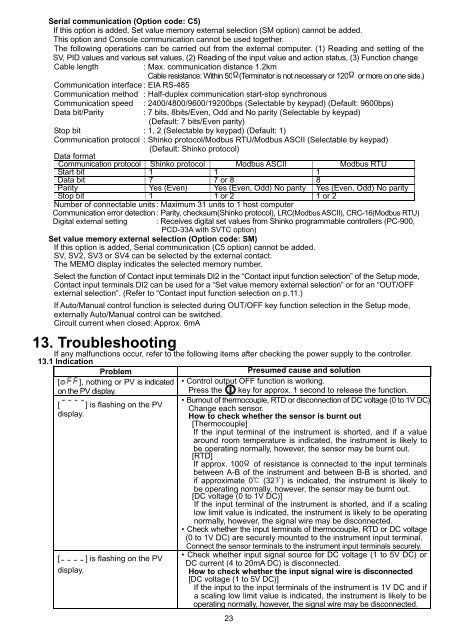
Serial communication (Option code: C5)If this option is added, Set value memory external selection (SM option) cannot be added.This option and Console communication cannot be used <strong>to</strong>ge<strong>the</strong>r.The follow<strong>in</strong>g operations can be carried out from <strong>the</strong> external computer. (1) Read<strong>in</strong>g and sett<strong>in</strong>g of <strong>the</strong>SV, PID values and various set values, (2) Read<strong>in</strong>g of <strong>the</strong> <strong>in</strong>put value and action status, (3) Function changeCable length: Max. communication distance 1.2kmCable resistance: With<strong>in</strong> 50 (Term<strong>in</strong>a<strong>to</strong>r is not necessary or 120 or more on one side.)Communication <strong>in</strong>terface : EIA RS-485Communication method : Half-duplex communication start-s<strong>to</strong>p synchronousCommunication speedData bit/Parity: 2400/4800/9600/19200bps (Selectable by keypad) (Default: 9600bps): 7 bits, 8bits/Even, Odd and No parity (Selectable by keypad)(Default: 7 bits/Even parity)S<strong>to</strong>p bit : 1, 2 (Selectable by keypad) (Default: 1)Communication pro<strong>to</strong>col : <strong>Sh<strong>in</strong>ko</strong> pro<strong>to</strong>col/Modbus RTU/Modbus ASCII (Selectable by keypad)(Default: <strong>Sh<strong>in</strong>ko</strong> pro<strong>to</strong>col)Data <strong>format</strong>Communication pro<strong>to</strong>colStart bit<strong>Sh<strong>in</strong>ko</strong> pro<strong>to</strong>col1 1Modbus ASCII1Modbus RTUData bit 7 7 or 8 8Parity Yes (Even) Yes (Even, Odd) No parity Yes (Even, Odd) No parityS<strong>to</strong>p bit 1 1 or 2 1 or 2Number of connectable units : Maximum 31 units <strong>to</strong> 1 host computerCommunication error detection : Parity, checksum(<strong>Sh<strong>in</strong>ko</strong> pro<strong>to</strong>col), LRC(Modbus ASCII), CRC-16(Modbus RTU)Digital external sett<strong>in</strong>g: Receives digital set values from <strong>Sh<strong>in</strong>ko</strong> programmable controllers (PC-900,PCD-33A with SVTC option)Set value memory external selection (Option code: SM)If this option is added, Serial communication (C5 option) cannot be added.SV, SV2, SV3 or SV4 can be selected by <strong>the</strong> external contact.The MEMO display <strong>in</strong>dicates <strong>the</strong> selected memory number.Select <strong>the</strong> function of Contact <strong>in</strong>put term<strong>in</strong>als DI2 <strong>in</strong> <strong>the</strong> “Contact <strong>in</strong>put function selection” of <strong>the</strong> Setup mode,Contact <strong>in</strong>put term<strong>in</strong>als DI2 can be used for a “Set value memory external selection” or for an “OUT/OFFexternal selection”. (Refer <strong>to</strong> “Contact <strong>in</strong>put function selection on p.11.)If Au<strong>to</strong>/Manual control function is selected dur<strong>in</strong>g OUT/OFF key function selection <strong>in</strong> <strong>the</strong> Setup mode,externally Au<strong>to</strong>/Manual control can be switched.Circuit current when closed: Approx. 6mA13. Troubleshoot<strong>in</strong>gIf any malfunctions occur, refer <strong>to</strong> <strong>the</strong> follow<strong>in</strong>g items after check<strong>in</strong>g <strong>the</strong> power supply <strong>to</strong> <strong>the</strong> controller.13.1 IndicationProblem[ ], noth<strong>in</strong>g or PV is <strong>in</strong>dicatedon <strong>the</strong> PV display.[ ] is flash<strong>in</strong>g on <strong>the</strong> PVdisplay.[ ] is flash<strong>in</strong>g on <strong>the</strong> PVdisplay.Presumed cause and solution• Control output OFF function is work<strong>in</strong>g.Press <strong>the</strong> key for approx. 1 second <strong>to</strong> release <strong>the</strong> function.• Burnout of <strong>the</strong>rmocouple, RTD or disconnection of DC voltage (0 <strong>to</strong> 1V DC)Change each sensor.How <strong>to</strong> check whe<strong>the</strong>r <strong>the</strong> sensor is burnt out[Thermocouple]If <strong>the</strong> <strong>in</strong>put term<strong>in</strong>al of <strong>the</strong> <strong>in</strong>strument is shorted, and if a valuearound room temperature is <strong>in</strong>dicated, <strong>the</strong> <strong>in</strong>strument is likely <strong>to</strong>be operat<strong>in</strong>g normally, however, <strong>the</strong> sensor may be burnt out.[RTD]If approx. 100 of resistance is connected <strong>to</strong> <strong>the</strong> <strong>in</strong>put term<strong>in</strong>alsbetween A-B of <strong>the</strong> <strong>in</strong>strument and between B-B is shorted, andif approximate 0 (32 ) is <strong>in</strong>dicated, <strong>the</strong> <strong>in</strong>strument is likely <strong>to</strong>be operat<strong>in</strong>g normally, however, <strong>the</strong> sensor may be burnt out.[DC voltage (0 <strong>to</strong> 1V DC)]If <strong>the</strong> <strong>in</strong>put term<strong>in</strong>al of <strong>the</strong> <strong>in</strong>strument is shorted, and if a scal<strong>in</strong>glow limit value is <strong>in</strong>dicated, <strong>the</strong> <strong>in</strong>strument is likely <strong>to</strong> be operat<strong>in</strong>gnormally, however, <strong>the</strong> signal wire may be disconnected.• Check whe<strong>the</strong>r <strong>the</strong> <strong>in</strong>put term<strong>in</strong>als of <strong>the</strong>rmocouple, RTD or DC voltage(0 <strong>to</strong> 1V DC) are securely mounted <strong>to</strong> <strong>the</strong> <strong>in</strong>strument <strong>in</strong>put term<strong>in</strong>al.Connect <strong>the</strong> sensor term<strong>in</strong>als <strong>to</strong> <strong>the</strong> <strong>in</strong>strument <strong>in</strong>put term<strong>in</strong>als securely.• Check whe<strong>the</strong>r <strong>in</strong>put signal source for DC voltage (1 <strong>to</strong> 5V DC) orDC current (4 <strong>to</strong> 20mA DC) is disconnected.How <strong>to</strong> check whe<strong>the</strong>r <strong>the</strong> <strong>in</strong>put signal wire is disconnected[DC voltage (1 <strong>to</strong> 5V DC)]If <strong>the</strong> <strong>in</strong>put <strong>to</strong> <strong>the</strong> <strong>in</strong>put term<strong>in</strong>als of <strong>the</strong> <strong>in</strong>strument is 1V DC and ifa scal<strong>in</strong>g low limit value is <strong>in</strong>dicated, <strong>the</strong> <strong>in</strong>strument is likely <strong>to</strong> beoperat<strong>in</strong>g normally, however, <strong>the</strong> signal wire may be disconnected.23