Technical DataMeasurement SpecificationsTemperature ranges: 700 - 1800°C (MB 18)800 - 2<strong>50</strong>0°C (MB 25)1000 - 3000°C (MB 30)Sub range:Any range adjustable within the temperature range,minimum span 51°CSpectral ranges: Channel 1: 0.9 µmChannel 2: 1.05 µmIR detector:Fiber:Uncertainty:(ε = 1, t 90= 1 s,T amb.= 23°C)Repeatability:(ε = 1, t 90= 1 s,T amb.= 23°C)Resolution:Silicon photo diode (Si/Si)MB 18: HD multi fiber 0.6 mm (green fiber mark)MB 25 and MB 30: HD mono fiber 0.2 mm(red fiber mark)Up to 1<strong>50</strong>0°C: 0.5% of measured value in °C + 2°CAbove 1<strong>50</strong>0°C:1% of measured value in °C0.2% of measured value in °C + 2°C0.1°C on interface and display < 0.1% oftemperature range at the analog outputExposure time t 90: 10 ms; adjustable to 0.01 s; 0.05 s; 0,25 s;1 s; 3 s; 10 sEmissivity slope K: 0.8 - 1.2 adjustable in steps of 0.001Emissivity ε: 5 - 100% adjustable in steps of 0.1%Switch-off level:Maximum valuestorage:Internal LC display:Digital interface:2% - <strong>50</strong>%, adjustableBuilt-in single or double storage. Clearing withadjusted t clear(off; 0.01 s; 0.05 s; 0.25 s;1 s; 5 s; 25 s), extern, via interface or automaticallywith the next measuring objectLC display for temperature indication or parametersettingsRS232 or RS485 addressable (half duplex),switchable; baud rate 1200 up to115200 BdParameters:Physical CharacteristicsAdjustable or readable at the instrument or viainterface:Measuring temperature, operation mode (ratio/mono), emissivity slope or emissivity, exposuretime, clear times for maximum value storage,hold function, analog output 0 - 20 or4 - 20 mA, temperature sub range, switch-off level,contamination limit, RS485 address, baud rate,RS485 wait time, temperature display in °C or °F,error status, maximum internal temperatureDimensions: See drawing on the right sideWeight: Converter: approx. 600 gOptical head: approx. 140 gFiber (2.5 m): approx. 630 gEnvironmental SpecificationsAmbienttemperature:Storagetemperature:Relative humidity:0 to <strong>50</strong>°C on the converter; 0 to 2<strong>50</strong>°C on side ofthe optical head-20 to 60°CNon condensing conditionsProtection class: IP65 (DIN 400<strong>50</strong>)ElectricalPower supply:Power consumption:Analog Output:Load:Isolation:Switch contact:Opto relay (AC/DC):CE label:24 V DC (18 - 36 V DC), ripple < <strong>50</strong>0 mVMax. 1 W0 - 20 mA or 4 - 20 mA (linear), switchable; testcurrent 10 mA or 12 mA by pressing test key0 - <strong>50</strong>0 ΩPower supply, analog output and digital interfaceare galvanically isolated from each otherSwitch contact for dirty window alarmmax. switch current: 0,5 A; max. switch supply60 V AC/DCAccording to EU directives about electromagneticimmunitySignal ProcessingAdvantages of the digital signal processing: The signal processing of series <strong>50</strong> pyrometers is fully digital, i. e. the detectorsignal are digitized immediately and digitally processed. With this technique an extremely high accuracy and repeatability isachieved.Accuracy:Temperaturerange:Output:Bus control:Calibration:The high accuracy is achieved by the digital linearisation of the sensor output as well as the digital compensationfor the ambient temperature.Due to the digital technique any temperature sub range within the full temperature range can be set. Theanalog measuring output corresponds automatically to the selected sub range. This setting of a sub rangedoes not effect the high accuracy and repeatability.The analog measuring outputs 0 ... 20 mA or 4 ... 20 mA are selectable as well as the serial digital interfacesRS232 or RS485. Additionally the interface allows the controlling of the pyrometer via PC.The serial interface RS485 facilitates the integration of the pyrometer into existing field bus systems.If necessary a calibration of the pyrometers can be done with help of a PC and a calibration source withoutopening the housing.
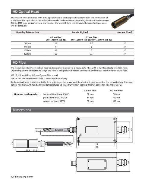
HD Optical HeadThe instrument is delivered with a HD optical head II that is specially designed for the connection ofa HD fiber. The optics has to be adjusted ex-works to the required measuring distance (possible range340 to 4<strong>50</strong>0 mm, measured from the front of the lens). Only in this distance the specified spot sizeswill be achieved.Measuring distance a [mm] Spot size M 90[mm] Aperture D [mm]0.6 mm fiber700 ... 1800°C (MB 18)0.2 mm fiber800 ... 2<strong>50</strong>0°C (MB 25);1000 ... 3000°C (MB 30)340 mm 5.1 1.7 17600 mm 9 3 171000 mm 15 5 174<strong>50</strong>0 mm 66 22 17HD FiberThe transmission between optical head and converter is done via a heavy duty fiber with a stainless steel protection hose.Depending on the temperature range the fiber is designed in different thicknesses and built as mono fiber or multi fiber.MB 18: HD multi fiber 0.6 mm (green fiber mark)MB 25 and MB 30: HD mono fiber 0.2 mm (red fiber mark)As the optical head contains only the lens system and the sensor and the electronics are located in the converter box, fiber andoptical head can withstand ambient temperatures up to 2<strong>50</strong>°C without cooling (fiber at converter side max. 125°C).0.6 mm fiber 0.2 mm fiberMinimum bending radius: for short time (max. 2<strong>50</strong>°C): 30 mm <strong>50</strong> mmpermanent (max. 2<strong>50</strong>°C): <strong>50</strong> mm 120 mmwound up (max. <strong>50</strong>°C): <strong>50</strong> mm 120 mmDimensionsAll dimensions in mm