The M67, M67S Infraducers - Contika
The M67, M67S Infraducers - Contika
The M67, M67S Infraducers - Contika

You also want an ePaper? Increase the reach of your titles
YUMPU automatically turns print PDFs into web optimized ePapers that Google loves.
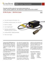
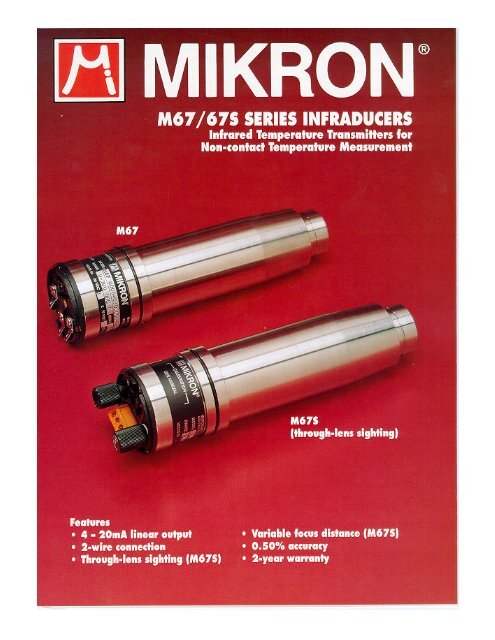
<strong>The</strong> <strong>M67</strong>, <strong>M67</strong>S <strong>Infraducers</strong><strong>The</strong> most dramatic design innovation(Patent No. 4,527,896) ininfrared temperature measurementfor process control in decades isnow available in 2 different versions.Innovative Design<strong>The</strong> <strong>M67</strong> and <strong>M67</strong>S <strong>Infraducers</strong>are 2-wire temperature transducers/transmitters for non-contacttemperature measurement. <strong>The</strong><strong>Infraducers</strong> represent the latest ininnovative technology, integratingexclusive, advanced electronicdesign with optical and mechanicalprecision that are the essence ofMikron’s infrared products. <strong>The</strong>irdesign from concept to finish isbased on simplicity of installationand maintenance. <strong>The</strong> <strong>Infraducers</strong>with their matchless array ofoptions and accessories, demonstrateMikron’s continuing leadershipin infrared temperaturemeasuring technology.Universal ApplicationCompletely self-contained, the <strong>M67</strong>and <strong>M67</strong>S <strong>Infraducers</strong> can be usedas true 2-wire temperature transducer/transmitterswhich produce astandard 4-20mA linear output.Powered by its current loop, eachInfraducer is completely compatiblewith any existing instrumentationfor recording or processcontrol. A rugged, stainless steelhousing, miniature size and lightweight made the <strong>Infraducers</strong>suitable for many applicationswhich up to now were the exclusivedomain of contact type temperaturetransmitters, such as thermocouples,resistance thermometers,etc. To insure minimum maintenanceand utmost reliability, the<strong>Infraducers</strong> have absolutely nomoving parts. When containedwithin its companion cooling jacketand air purge assembly, eachInfraducer can withstand the mostpunishing conditions found inindustry. <strong>The</strong> <strong>Infraducers</strong> haveuniversal application in virtuallyany type of industry. Typicalapplication areas where infraredhas successfully been usedinclude: cement, ceramics,chemicals, food, glass, heattreating, metals, paper, plastics,power, printing, petrochemicals,robotics, rubber, semiconductors,textiles, vacuum systems...Field InterchangeabilitySuperior design not only insuresaccuracy and long term reliability,it also insures interchangeabilitybetween <strong>Infraducers</strong> ofthe same model with ±0.50%accuracy. For especially demandingapplications, the <strong>Infraducers</strong>have a digital emissivity controlthat can be set with a resolutionof 0.01. This insures that, shouldone of the <strong>Infraducers</strong> need to bereplaced, the replacement unit canbe preset in every aspect beforeinstallation.Application AssistanceMany years of experience insolving unusual and difficultinfrared temperature measurementand control problemsqualify our sales and applicationengineering staffs to offer solutionsto the most challengingapplications encountered inindustry.Quality AssuranceReliability is never taken forgranted at Mikron. After finalcalibration, every Infraducer istested and burned-in for a weekand rigorously subjected to aperiod of thermal cycling andvibration to verify calibrationdata.WarrantyAll <strong>Infraducers</strong> are covered by atwo-year warranty period.DIGITAL EMISSIVITYCONTROLTERMINALSCREWSMOLDED INTOHIGH STRENGTHTHERMOPLASTIC<strong>M67</strong>INFRADUCERSTAINLESS STEELHOUSING FOROPTICS &ELECTRONICS<strong>M67</strong>REARPANELPROTECTIVEREAR COVER
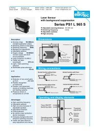
VISUAL SIGHTING 4DIGITAL EMISSIVITYCONTROL<strong>M67</strong>SREARPANELRETICLE DEFINES EXACTAREA OF TEMPERATUREMEASURMENTEYE PIECEOUTPUT TERMINALSTRIPFOCUSSING KNOB(ADJUSTABLE FROMREAR PANEL)<strong>M67</strong> Infraducer<strong>The</strong> <strong>M67</strong> is designed to handle most standard industrialapplications. When powered by an 18 to 40VDC supply, itprovides a 4-20mA linear output for interface with indicationand recording instrumentation. Its two-wire design simplifiesinstallation, operation and maintenance. Screw terminalsallow easy yet secure connection. <strong>The</strong> <strong>M67</strong> has a fixedoptical system. That is, target size is determined by thedistance between the sensor and the target area. It is recommendedfor applications where target size is known andoperating distance is relatively constant.<strong>M67</strong>S Infraducer<strong>The</strong> <strong>M67</strong>S contains all the features of the <strong>M67</strong> with theadded benefit of through-lens sighting. <strong>The</strong> <strong>M67</strong>S incorporatesa high quality, high precision variable focus opticalsystem that allows sharp focussing on the desired target fromabout 2” to infinity.Focussing is executed by turning the focussing knob on therear panel of the instrument. <strong>The</strong> <strong>M67</strong>S allows for precisionpinpointing of small target areas. <strong>The</strong> user simplyadjusts the instrument until the desired target is locatedwithin the reticle. <strong>The</strong> <strong>M67</strong>S is available in three distinctversions. <strong>The</strong> first will make accurate measurements atdistances of 14” to infinity, the second has a working rangeof 6” to 14” and the third is designed to measure .06”(1.5mm) target at 2” distance. See the Selection Guide fordetails.NIST Traceable Calibration CertificateMikron infrared thermometers are supplied with a finalcalibration certificate at no charge. <strong>The</strong> additional assuranceof a calibration certificate traceable to NationalInstitute of Science and Technology (NIST), is optionallyavailable at additional cost. Please refer to Options in theSpecifications.TYPICAL INFRADUCER LOOP WIRING<strong>M67</strong>INFRADUCERUP TO 5000 FT(1.5KM)DIGITALINDICATORANALOGINDICATORRECORDERFOR HAZARDOUSLOCATION USEFM APPROVEDVERSION OFMODEL <strong>M67</strong>SHIELDPOWER SUPPLY18 TO 40VDCDATA LOGGERCONTROLLER
PHow to select the right Infraducer<strong>The</strong>re are two basic Infraducer shell designs, one for the standard <strong>M67</strong> and the other for the <strong>M67</strong>S. Each ofthese is available with a variety of temperature spans, spectral responses, and optical characteristics to meetspecific applications. In addition each design is available in a three-wire version which provides a choice of awide variety of optional outputs. A large selection of protective and mounting accessories is available to meetthe customer’s needs. <strong>The</strong> Mikron protective jacket is recommended whenever physical limitation allows. <strong>The</strong>protective jacket allows more rigid installation of the Infraducer and minimizes the influence of ambient thermaltransients. When dust and other contaminants are present, the air purge assembly guarantees a clear viewingpath for the optical systems. An auxiliary spring-loaded adjustable flange is also available when variable aimingcapabilities are desired.To order the unit just follow these simple steps and insert the proper codes in the boxes below.Step No.1. Determine the desired Infraducer version based on focussing and output requirements. Place the desiredmodel number in box No. 1 below.2. Select the application requirement in the second column of the chart, select temperature range and units (F orC) from ranges listed across from your application. Insert ranges and units in boxes marked No. 2, filling inall blanks with zeros.3. Insert in the box No.3, the spectral response code previously selected.4. If you selected either the <strong>M67</strong> or <strong>M67</strong>S in box No.1, insert code letter L in box 4 for 4-20mA linear output.If you selected the <strong>M67</strong>W or <strong>M67</strong>SW, insert code letter U in box 4 and specify desired output in writing.See Note 2 for available optional outputs.5. If you selected an <strong>M67</strong> of <strong>M67</strong>W proceed to step 5A. if you selected an <strong>M67</strong>S or <strong>M67</strong>SW proceed to step5B.5A.Read the section titled “Optical Resolution” for the <strong>M67</strong> to the right. If standard factory focusing is acceptable,insert code S in box No. 5A. if close focussing is required insert code U in box No.5A and specifydesired focus distance and target size in writing. Proceed to step No.6.5B.Read the section titled “Optical Resolution” as it relates to the <strong>M67</strong>S. Determine the desired working distanceof the instrument and insert the code number in box No. 5B.6. Specify desired initial factory set output response time by inserting the proper code letter in box No. 6.Output response time is field adjustable should factory setting need to be changed. When code letter E isselected, specify in writing desired output response time.7. Designate the type of protective jacket required by code I for protective jacket without cooling capability ofcode J for protective jacket with cooling. Use of protective jacket in all cases where physical limitations donot exist is highly recommended. If no protective jacket is desired insert letter O.8. Select the air purge assembly when dust or other airborne contaminants are present. Specify code L whenindustrial air is used or code N when high quality instrument air is available. Specify code letter O if the airpurge is not required.9. In the box labeled 8 specify letter P if adjustable aiming flange is desired, O if not.Notes:1. Infraducer with M spectral band is only available in versions with fixed focussed distance.2. For these
1BASIC MODEL(SEE NOTE 1.)TYPICALAPPLICATIONMOST COMMON FOR LOWTEMPERATURE APPLICATIONS2 TEMPERATURE 3 SPECTRAL 4 OUTPUT TYPE FIELDRANGERESPONSE(See note 3.) OF VIEW(See note 2.)°FRATIO°C MICRONS CODECODE
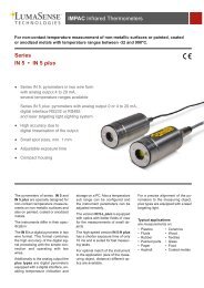
5A 5A <strong>M67</strong>, <strong>M67</strong>WFOCUSSED DISTANCESTANDARDCODES5A6 OUTPUTRESPONSE TIME(Field Adjustable)CODESABCDEFACTORYSETTINGSEE SPECS300mSECOND1 SECOND3 SECONDS10 SECONDSOTHERS6PROTECTIVE7 JACKET5AWITHOUTCOOLINGWITH COOLINGNOCODEIJO78OPTIONAL(Specify desired focusdistance in writing.)8 AIR PURGEASSEMBLYYESNOUCODELO1 23 49<strong>M67</strong> 0 0 0 0_0 5 0 0<strong>M67</strong>S 0 0 0 0 5 0_0 0FFBBLLS B I1 B ILLPP9AIMINGFLANGEYESNOCODEPO5B5B<strong>M67</strong>S, <strong>M67</strong>SWOPERATING DISTANCE14” (350) TO INFINITY6” (150) TO 14” (350)2” (50) FIXEDCODE123OPTICAL RESOLUTION-<strong>M67</strong>S AND <strong>M67</strong>SWThree different lenses are available for the <strong>M67</strong>S and <strong>M67</strong>SW. the one you shouldchoose depends on the desired working distance of the unit. <strong>The</strong> first version isdesigned to measure temperature at distances of 14” to infinity. <strong>The</strong> second versionhas a working area of 6” to 14”. <strong>The</strong> third version is fixed to measure temperaturesat a 2” distance. Proper focussing is achieved by mounting the unit at the desireddistance and adjusting the focussing knob on the rear panel of the instrument untilthe target comes into clear view in the reticle. When the target is in focus to theeye, it is also in focus to the detector. Should you wish to move the instrument,remember to stay within the prescribed working distance and simply refocus uponthe target after counting the instrument in its new location.A typical field of view diagram is shown at right:Target size is determined by the formula: Measuring Distance (D)Target size (D) =Field of View RatioExample: <strong>M67</strong>S, version 1 with 30:1 FOV focussed at 15”Minimum target sizes are shown in the table below:TARGET SIZE(d)DISTANCE(D)Field ofView15:130:190:1180:1Version 1Focus 14” to infinityMin target of 0.93” at 14”distanceMin target of 0.47” at 14”distanceMin target of 0.16” at 14”distanceMin target of 0.07” at 14”distanceVersion 2Focus 6” to 14”Min target of 0.40” at 6”distanceMin target of 0.20” at 6”distanceMin target of 0.07” at 6”distanceNot AvailableVersion 3Focus at 2”Min target of 0.13” at2” distanceMin target of 0.06” at2” distanceNot AvailableNot Available
5AOPTICAL RESOLUTION<strong>M67</strong> and <strong>M67</strong>W<strong>The</strong> <strong>M67</strong> and <strong>M67</strong>W feature fixed optical systems inwhich the target size is determined by the distancebetween the target area and the sensor. <strong>The</strong> field ofview of the instrument is determined by the spectralresponse and temperature range that you have alreadyselected and has been pre-determined for you. Eachinstrument is factory focused for the most frequentlyused distances and follows its corresponding field ofview diagram depicted in the chart to the right.Close focus distances are available to facilitate accuratemeasurements of target areas smaller than 1” (25mm).Minimum target size is determined by the formula:Min. Target Size =Focussed distance to the <strong>M67</strong>Field of View RatioA typical close focussing example and correspondingfield of view diagram are shown below.Example: determine minimum target size for focusdistance of 6” and FOV ratio of 30:1Min. Target Size = 6” / 30 =0.2”TARGET DIADISTANCETARGET DIA(mm)DISTANCE0.5”0(13)0.2”6”0 15cm2.5”30”(5) (64)76cmStandard Field of View (FOV)Diagrams(See note 3)FOV RATIO = 15:1min target diameter1”(25)1”(25)0 15”(38cm)Distance from <strong>M67</strong>FOV RATIO = 30:1min target diameter1”(25)01”(25)30”(75cm)Distance from <strong>M67</strong>FOV RATIO = 90:1min target diameter0.5”(13)01.13”(29)8ft.(2.4m)Distance from <strong>M67</strong>2.2”(56)12ft.(3.6m)3.8”(96)36”(91cm)3”(76)60”(150cm)3.27”(83)16ft.(4.8m)MINFOCUSSABLEDESTANCEFORCLOSEFOCUS1”(2.5 cm)3”(7.6 cm)6”(15 cm)FOV RATIO = 180:1min target diameter(Minimum focussable distance for each FOVis shown to the right.)0.5”(13)01”(25)15ft.(4.6m)2.5”(64)30ft.(9.1m)12”(30 cm)Distance from <strong>M67</strong>
Accuracy: ** ±0.5% of full scale or 1.0°C (1.8°F) whichever is greater.Resolution: ±0.1% of full scale span (FSS)Repeatability: ±0.2% of full scale span (FSS)Emissivity: Digital setting 0.10-0.99 with 0.01 stepOptical System: <strong>M67</strong>S. <strong>M67</strong>SW: Non-parralex refractive optics focussable fromrear panel.Field of View: <strong>M67</strong>S, <strong>M67</strong>SW: Visual sighting 4°. Infrared see FOV diagram for<strong>M67</strong> and optical resolution for <strong>M67</strong>S.Focussing Distance: <strong>M67</strong>S. <strong>M67</strong>SW: Dioper typeInput Voltage: 24VDC nominalInput Voltage Range: 18-40VDCOutput Current Span: 4-20mA linear standardMinimum Output Current 3.8mAMaximum Output Current 32mAOthers see selection chartResponse Time: 50mS for codes H and Q spectral response, 100mS for all others.Response time defined as time required for output to reach 95% of its final value.(See note 5)Load Resistance Max: 100ohms for 20V input voltage, 300ohms for 24 inputvoltage.Electrical Connections: 1) <strong>M67</strong>-two terminal screws molded into high strength,high temperature thermoplastic 2) <strong>M67</strong>S, <strong>M67</strong> and <strong>M67</strong>SW- Four terminalsOperating Ambient Temperature:Without Cooling Jacket: 0 to 60°C (32 to 140°F)With Air Purge Assembly: 120°C (250°F)With Cooling Jacket: Up to 315°C (600°F)Storage Ambient Temperature: -30 to 80°C (-20 to 160°F)Relative Humidity: 90% Non-condensingVibration: <strong>M67</strong>, <strong>M67</strong>W- 3 g’s any axis continuousShock: <strong>M67</strong>, <strong>M67</strong>W- 50 g’sHousing Material: Stainless steelDimensions: 1) <strong>M67</strong> and <strong>M67</strong>W –2.0” dia. x 7.9” long (50mm x 200mm) 2)<strong>M67</strong>S and <strong>M67</strong>SW – 2.0” dia. x 8.0” long (50mm x 203mm)Weight: 1.9 lbs. (0.9kg)Mounting: Support block with four 0.200” (5mm) dia. holes and “U” clamp. Formore secure mounting, use of protective jacket is recommended.Optical Features:NIST Traceable Calibration Certificate: Minimum of three points on instrumenttemperature scale. Additional points as required at extra cost per point.FM Approved Version: See accessories (electrical)Peak/Valley Picker: See accessories (electrical)**1. Accuracy is stated for target emissivity of 1.0 at specified focussed distance andtarget having sufficient diameter to eliminate background influence.**2. Accuracy is stated for input voltage of 24VDC and load resistance of 250ohms.Accessories (Mechanical)Protective Jacket and End Cap<strong>The</strong> cast aluminum jacket and end cap protects the Infraducer fromphysical damage when located in environments of heavy industry andalso dampens the effect of rapid ambient changes. <strong>The</strong> precisionmachining of the protective jacket allows for easy removal andreplacement of the sensor head with no loss of alignment. In highambients when temperature exceeds the maximum rated temperatureof the Infraducer, the use of a protective jacket with cooling capabilityis mandatory. Extensive research and testing of the jacket assuresuniform cooling along its entire length and simultaneously isolates theInfraducer form thermal influence. While airflow alone is sufficientfor light cooling, water must be used for moderate and heavy cooling.Ambient temp.°F °C1502002503003504004505006006595120150175205230260315Gal./Hr.0.20.61.02.03.04.06.010.020.0Liters/Hr.0.82.33.87.611.415.222.737.876.0Inlet coolant temperature assumed at 68°F (20°C)Air Purge and Cooling AssemblyThough simple in outward appearance, this assembly performs threevery important functions- purging, aiming and localized cooling. Airpurging of the optics is extremely important when airborne contaminantscan build up on the lens and eventually “blind” the sensor head.In contrast to many air purge systems currently in use which actuallydevelop a negative pressure vortex and contribute to the build up ofcontaminants, the Mikron air purge assembly has been carefullyengineered to prevent this build-up of from occurring. A flow of only75 CFH (2CMH) of normally clean industrial air will keep the opticsclean indefinitely.<strong>The</strong> metal sight tube is designed for installations where it is desirableto augment the air purge and facilitate approximate aiming of theInfraducer.<strong>The</strong> cooling plate section of the air purge assembly allows the coolantto circulate in a stainless steel chamber, which allows cooling ofInfraducer up to ambient temperature of 120°C (250°F). <strong>The</strong> airpurge assembly depends upon the protective jacket for mounting.Aiming Flange AssemblyFor installations requiring durable mounting of the sensor head whileallowing for adjustment of the optical path to a maximum of 5° in anydirection from normal to the mounting plate. Specify PN 11649-2when ordered separately.
Accessories (Electrical)Precision Digital Process MetersFM Approved Model<strong>The</strong> modes <strong>M67</strong> Infraducer has been approved by Factory Mutual(FM) for usage in hazardous environments. When used inconjunction with the optional barriers, the entire system will berated intrinsically safe. Approvals are for Class I, II or III,Division 1, Group A B, C, D, E, F and G. At the time of orderplease specify that the FM Approved version is required.Peak/Valley Picker<strong>The</strong> <strong>M67</strong> with optional built-inpeak/valley picker circuitryallows a fast response to temperaturerise and adjustable slowdecay of output when temperaturefalls. This feature isinvaluable in applications wherewide temperature variations areencountered.43OUTPUT<strong>M67</strong>SENSOR HEADHOT OBJECT21CONVEYORPEAK PICKER OUTPUTMINIMUM DICAY RATESFASTER DECAT RATESMikron M60TS<strong>The</strong> M60TS is a 1/8 DIN digital process meter with front panelkeyboard programmability. <strong>The</strong> M60TS is available in both 3 ½digit (for temperature below 2000°) and 4 digit (for temperatureabove 2000°) versions. It provides monitoring and display of theminimum and maximum process value input with keypad reset asa standard feature. <strong>The</strong> M60TS contains a built-in 20VDC powersupply which simplifies connection to the Infraducer.Mikron M60TD<strong>The</strong> M60TD offers all of the features of the M60TS as well asadjustable high and low set points. Sit point adjustments aremade on the front panel keypad. <strong>The</strong> keypad requires coded entryto protect against accidental and unauthorized changes.For more information about ant of these meters, please requestMikron Accessories Bulletin Number1OUTPUT1 2 3 4TIMEACTUALTEMPERATUREOUTPUT TRACE FOR A TYPICALCONVEYOR SYSTEM SHOWING PEAKEDOUTPUTS<strong>M67</strong>EM Electronic Module<strong>The</strong> <strong>M67</strong>EM is a basic electronic moduledesigned to support the <strong>M67</strong> Infraducer onthose installations where a remote peak/valleypicker is the dominant electronic requirement.<strong>The</strong> <strong>M67</strong>EM operates from 115VAC current(220VA optional) and provides a 24 VDCvoltage for a loop current.Power Supplies<strong>The</strong>se power supplies provide either a 24 or 40V current to powerthe sensor head. <strong>The</strong> low profile, sealed and rugged package sedesigned for chassis mounting. <strong>The</strong> front-mounted terminalbarrier strip is perfect for isolation between input and outputvoltages. A current limiting feature protects the power supplywhen short circuit occurs. Four tapped holes are provided formounting. Available in both 115 and 230VAC versions.<strong>M67</strong>EM SpecificationsInput Signal Requirements: 4-20mA linear from <strong>M67</strong> outputResponse Time Adjust: 10mS to 10 sec. Field adjustablePeak/Valley Picker Decay Rate: (Valley picker optional)Continuously adjustable between 0.01 and 10% of full scale/second.Peak Picker Controls: (Valley Picker optional) On, Cancel andReset from front panel. Remote Reset actuated by external SPSTswitch (customer supplied).Standard Outputs (Linear): 0-1V full scale; 0-50mVDC fullscale; 1mV/ °F or C; 4-20mADC, 650 ohms max.Output Supply Voltage: +24VDC to power <strong>M67</strong>Ambient Temperature Range: 0°C to 50°C (32°F to 120°F)Size: 64mm(W) x 128mm(H) x 230mm(D) (2.5 in. x 5.0 in. x 9.0in.)Panel Cutout: 58mm x 108mm (2.25 in. x 4.25 in.)Power: 115VAC ±10% 50/60Hz (230VAC optional) 30 wattsInput Voltage±10%50-60Hz115VAC230VAC115VAC230VACOutputVoltage24VDC24VDC40VDC4OVDCMax.LoadCurrent100mA100mA60mA60mAPart No.11846-111846-111846-211846-4Made in U.S.A.<strong>The</strong> <strong>M67</strong> Series is designed and built by Mikron, the leadinginnovator in infrared thermometry.MIKRON INSTRUMENT COMPANY, INC., 16 Thornton Road, Oakland, New Jersey 07436 USATEL., 201-405-0900 FAX: 201-405-0090 TOLL FREE HOT-LINE: 800-631-0176