MEPC 49/22/Add.2 ANNEX 13 RESOLUTION MEPC.107(49 ... - Bimco
MEPC 49/22/Add.2 ANNEX 13 RESOLUTION MEPC.107(49 ... - Bimco
MEPC 49/22/Add.2 ANNEX 13 RESOLUTION MEPC.107(49 ... - Bimco
- No tags were found...

Create successful ePaper yourself
Turn your PDF publications into a flip-book with our unique Google optimized e-Paper software.
<strong>MEPC</strong> <strong>49</strong>/<strong>22</strong>/<strong>Add.2</strong><strong>ANNEX</strong> <strong>13</strong><strong>RESOLUTION</strong> <strong>MEPC</strong>.107(<strong>49</strong>)Adopted on 18 July 2003REVISED GUIDELINES AND SPECIFICATIONS FOR POLLUTION PREVENTIONEQUIPMENT FOR MACHINERY SPACE BILGES OF SHIPSTHE MARINE ENVIRONMENT PROTECTION COMMITTEE,RECALLING Article 38(a) of the Convention on the International Maritime Organizationconcerning the functions of the Committee,NOTING resolution <strong>MEPC</strong>.60(33) adopted on 30 October 1992 by which the MarineEnvironment Protection Committee adopted, at its thirty-third session, the revised Guidelines andSpecifications for Pollution Prevention Equipment for Machinery Space Bilges of Ships andinvited Governments to adopt and apply them to the maximum possible extent which they foundreasonable and practicable and to report to the Organization the results of such application,NOTING FURTHER the provisions of regulation 16(5) of Annex I of the InternationalConvention for the Prevention of Pollution from Ships, 1973, as modified by the Protocolof 1978 thereto (MARPOL 73/78), in which reference is made to the above-mentionedspecifications,RECOGNIZING the advancement of technology, as well as the amendments to Annex Iof MARPOL 73/78 on its operational discharge requirements which were adopted by the MarineEnvironment Protection Committee in 1992 and which entered into force on 6 July 1993,HAVING CONSIDERED, at its forty-ninth session, the Revised Guidelines andSpecifications developed by the Sub-Committee on Ship Design and Equipment in the light ofthe requirements of Annex I of MARPOL 73/78,1. ADOPTS the Revised Guidelines and Specifications for Pollution Prevention Equipmentfor Machinery Space Bilges of Ships, the text of which is set out in the annex to this resolution,which supersedes the recommendations contained in resolution <strong>MEPC</strong>.60(33);2. INVITES Governments to:(a)(b)implement the Revised Guidelines and Specifications and apply them so that allequipment installed on board on or after 1 January 2005 meets these RevisedGuidelines and Specifications in so far as is reasonable and practicable; andprovide the Organization with information on experiences gained from theirapplication and, in particular, on successful testing of equipment against theSpecifications;I:\<strong>MEPC</strong>\<strong>49</strong>\<strong>22</strong>-ADD.2.DOC
<strong>MEPC</strong> <strong>49</strong>/<strong>22</strong>/<strong>Add.2</strong><strong>ANNEX</strong> <strong>13</strong>Page 23. REQUESTS the Secretariat, on the basis of information received, to maintain and updatea list of approved equipment and to circulate it once a year to Governments; and4. FURTHER INVITES Governments to issue an appropriate “Certificate of type approval”as referred to in paragraph 5.2.1 of the Specifications and to recognize such certificates issuedunder the authority of other Governments as having the same validity as certificates issued bythem.I:\<strong>MEPC</strong>\<strong>49</strong>\<strong>22</strong>-ADD.2.DOC
<strong>MEPC</strong> <strong>49</strong>/<strong>22</strong>/<strong>Add.2</strong><strong>ANNEX</strong> <strong>13</strong>Page 3<strong>ANNEX</strong>REVISED GUIDELINES AND SPECIFICATIONS FOR POLLUTION PREVENTIONEQUIPMENT FOR MACHINERY SPACES OF SHIPSTABLE OF CONTENTS1 Introduction2 Background3 Definitions4 Technical specifications5 Specifications for type approval testing of pollution prevention equipment6 Installation requirements<strong>ANNEX</strong>Part 1 - Test and performance specifications for type approval of 15 ppm bilge separatorsPart 2 - Test and performance specifications for type approval of 15 ppm bilge alarmsPart 3 - Specifications for environmental testing for type approval of pollution preventionequipmentPart 4 - Method for the determination of the oil contentPart 5 - Documentation of approvalAPPENDIX 1 - Certificate of type approval for 15 ppm bilge separatorAPPENDIX 2 - Certificate of type approval for 15 ppm bilge alarmI:\<strong>MEPC</strong>\<strong>49</strong>\<strong>22</strong>-ADD.2.DOC
<strong>MEPC</strong> <strong>49</strong>/<strong>22</strong>/<strong>Add.2</strong><strong>ANNEX</strong> <strong>13</strong>Page 4REVISED GUIDELINES AND SPECIFICATIONS FOR POLLUTION PREVENTIONEQUIPMENT FOR MACHINERY SPACE BILGES OF SHIPS1 INTRODUCTION1.1 General1.1.1 The specifications in respect of 15 ppm Bilge Separators are considered to be applicablefor use in conjunction with oily bilge-water and ballast water from fuel oil tanks, as these are of alow or medium capacity, and are conditioned by the need to avoid discharging oil mixtures withan oil content more than 15 ppm of the mixture.1.1.2 It is recognized that the development and testing of high capacity separating equipmentdesigned for dealing with effluent from cargo tanks on tankers pose special problems and suchequipment does not require to be tested under these specifications. Such development and testsshould not be hindered and Administrations should be prepared to accept deviations from thesespecifications when they are considered necessary in this context.1.1.3 It should be understood that a 15 ppm Bilge Separator must be capable of handling anyoily mixtures from the machinery space bilges and be expected to be effective over the completerange of oils which might be carried on board ship, and deal satisfactorily with oil of very highrelative density, or with a mixture presented to it as an emulsion. Cleansing agents, emulsifiers,solvents or surfactants used for cleaning purposes may cause the bilge water to emulsify. Propermeasures should be taken to minimize the presence of these substances in the bilges of a ship.With the possibility of emulsified bilge water always present the 15 ppm Bilge Separator must becapable of separating the oil from the emulsion to produce an effluent with an oil content notexceeding 15 ppm.1.1.4 Where a range of 15 ppm Bilge Separators of the same design, but of different capacities,requires certification in accordance with these specifications, the Administration may accept testsin two capacities within the range, in lieu of tests on every size, providing that the two testsactually performed are from the lowest quarter and highest quarter of the range.Training1.1.5 Ship staff training should include familiarization in the operation and maintenance of theequipment.Maintenance1.1.6 The routine maintenance of the 15 ppm Bilge Separator and the 15 ppm Bilge Alarmsystem should be clearly defined by the manufacturer in the associated Operating andMaintenance Manuals. All routine and repair maintenance to be recorded.1.1.7 Regulations referred to in these Guidelines and Specifications are those contained inAnnex I of MARPOL 73/78.I:\<strong>MEPC</strong>\<strong>49</strong>\<strong>22</strong>-ADD.2.DOC
<strong>MEPC</strong> <strong>49</strong>/<strong>22</strong>/<strong>Add.2</strong><strong>ANNEX</strong> <strong>13</strong>Page 6.1 the 15 ppm Bilge Separator should be tested for type approval in accordance withthe procedures described in part 1 of the annex, subject to environmental testsspecified in part 3 of the annex; and.2 the oil content meter for the 15 ppm Bilge Separator effluent discharge,hereinafter referred to as the 15 ppm Bilge Alarm should be tested for typeapproval in accordance with part 2 of the annex, subject to the environmental testsspecified in part 3 of the annex.2 BACKGROUND2.1 The requirements of Annex I of MARPOL 73/78 relating to pollution preventionequipment for ships are set out in regulation 16, which stipulates that ships of 400 gross tonnageand above should be installed with approved equipment.2.2 Regulation 16(5) stipulates that the oil content of the effluent from 15 ppm BilgeSeparators should not exceed 15 ppm. The 15 ppm Bilge Alarm shall activate to indicate whenthis level cannot be maintained, and initiate automatic stop of overboard discharge of oilymixtures where applicable.3 DEFINITIONS3.1 Pollution prevention equipmentFor the purpose of these Guidelines and Specifications pollution prevention equipment installedin a ship in compliance with regulation 16 comprises:.1 15 ppm Bilge Separator;.2 15 ppm Bilge Alarm; and.3 automatic stopping device3.2 15 ppm Bilge Separator“15 ppm Bilge Separator” may include any combinations of a separator, filter, coalescer or othermeans, and also a single unit designed to produce an effluent with oil content not exceeding15 ppm.3.3 15 ppm Bilge AlarmThe alarm arrangements specified in regulation 16(5) are referred to in these Guidelines andSpecifications as a “15 ppm Bilge Alarm”.3.4 ppm“ppm” means parts of oil per million parts of water by volume.I:\<strong>MEPC</strong>\<strong>49</strong>\<strong>22</strong>-ADD.2.DOC
<strong>MEPC</strong> <strong>49</strong>/<strong>22</strong>/<strong>Add.2</strong><strong>ANNEX</strong> <strong>13</strong>Page 73.5 ppm display“ppm display” is a numerical scale display of the 15 ppm Bilge Alarm.3.6 Automatic Stopping DeviceThe automatic stopping device is a device used, where applicable, to automatically stop anydischarge overboard of oily mixture when the oil content of the effluent exceeds 15 ppm. Theautomatic stopping device should consist of a valve arrangement installed in the effluent outletline of the 15 ppm Bilge Separator which automatically diverts the effluent mixture from beingdischarged overboard back to the ship’s bilges or bilge tank when the oil content of the effluentexceeds 15 ppm.4 TECHNICAL SPECIFICATIONS4.1 15 ppm Bilge Separator4.1.1 The 15 ppm Bilge Separator should be strongly constructed and suitable for shipboarduse, bearing in mind its intended location on the ship.4.1.2 It should, if intended to be fitted in locations where flammable atmospheres may bepresent, comply with the relevant safety regulations for such spaces. Any electrical equipmentwhich is part of the 15 ppm Bilge Separator should be based in a non-hazardous area, or shouldbe certified by the Administration as safe for use in a hazardous area. Any moving parts whichare fitted in hazardous areas should be arranged so as to avoid the formation of static electricity.4.1.3 The 15 ppm Bilge Separator should be so designed that it functions automatically.However, fail-safe arrangements to avoid any discharge in case of malfunction should beprovided.4.1.4 Changing the feed to the 15 ppm Bilge Separator from bilge water to oil, bilge water toemulsified bilge water, or from oil and/or water to air should not result in the dischargeoverboard of any mixture containing more than 15 ppm of oil.4.1.5 The system should require the minimum of attention to bring it into operation. In the caseof equipment used for engine room bilges, there should be no need for any adjustment to valvesand other equipment to bring the system into operation. The equipment should be capable ofoperating for at least 24 hours of normal duty without attention.4.1.6 All working parts of the 15 ppm Bilge Separator which are liable to wear or to damageshould be easily accessible for maintenance.4.2 15 ppm Bilge Alarm4.2.1 These Specifications relate to 15 ppm Bilge Alarms.4.2.2 The 15 ppm Bilge Alarm should resist corrosion in conditions of the marine environment.4.2.3 The 15 ppm Bilge Alarm should, if intended to be fitted in locations where flammableatmosphere may be present, comply with the relevant safety regulations for such spaces. Anyelectrical equipment which is part of the 15 ppm Bilge Alarm should be placed in aI:\<strong>MEPC</strong>\<strong>49</strong>\<strong>22</strong>-ADD.2.DOC
<strong>MEPC</strong> <strong>49</strong>/<strong>22</strong>/<strong>Add.2</strong><strong>ANNEX</strong> <strong>13</strong>Page 95 SPECIFICATION FOR TYPE APPROVAL TESTING OF POLLUTIONPREVENTION EQUIPMENT5.1 Testing requirementsThe production model of pollution prevention equipment, for which the approval will apply,should be identical to the equipment, type-tested in accordance with the test and performancespecifications contained in part 1 or 2 of the annex to these Guidelines and Specifications. Theequipment should also be type-tested in accordance with the specifications for environmentaltesting contained in part 3 of the annex.5.2 Approval and certification procedures5.2.1 Pollution prevention equipment which in every respect fulfils the requirements of theseGuidelines and Specifications may be approved by the Administration for fitting on board ships.The approval should take the form of a certificate of type approval specifying the mainparticulars of the apparatus and any limiting conditions on its usage necessary to ensure itsproper performance. Such certificate should be issued in the format shown in part 5 of the annex.A copy of the certificate of type approval for pollution prevention should be carried on boardships fitted with such equipment at all times.5.2.2 A certificate of type approval for a 15 ppm Bilge Alarm should be issued and retained onboard.5.2.3 Approved pollution prevention equipment may be accepted by other countries for use ontheir vessels on the basis of the first trials, or after new tests carried out under the supervision oftheir own representatives. Should equipment pass a test in one country but fail a test of a similarnature in another country, then the two countries concerned should consult one another with aview to reaching a mutually acceptable agreement.6 INSTALLATION REQUIREMENTS6.1 15 ppm Bilge Separator6.1.1 For future inspection purposes on board ship, a sampling point should be provided in avertical section of the water effluent piping as close as is practicable to the 15 ppm BilgeSeparator outlet. Re-circulating facilities should be provided, after and adjacent to the overboardoutlet of the stopping device to enable the 15 ppm Bilge Separator system, including the 15 ppmBilge Alarm and the automatic stopping device, to be tested with the overboard discharge closed(see figure 1).The re-circulating facility should be so configured as to prevent under all operating conditionsany by-pass of the oily-water-separator.6.1.2 The capacity of the supply pump should not exceed 110% of the rated capacity of the15 ppm Bilge Separator with size of pump and motor to be stated on the Certificate of TypeApproval.6.1.3 The 15 ppm Bilge Separator should be fitted with a permanently attached plate giving anyoperational or installation limits considered necessary by the manufacturer or the Administration.6.1.4 A vessel fitted with a 15 ppm Bilge Separator should, at all times, have on board a copyof the Operating and Maintenance manuals.I:\<strong>MEPC</strong>\<strong>49</strong>\<strong>22</strong>-ADD.2.DOC
<strong>MEPC</strong> <strong>49</strong>/<strong>22</strong>/<strong>Add.2</strong><strong>ANNEX</strong> <strong>13</strong>Page 106.2 15 ppm Bilge Alarm6.2.1 The layout of the installation should be arranged so that the overall response time(including the response time of the 15 ppm Bilge Alarm) between an effluent discharge from the15 ppm Bilge Separator exceeding 15 ppm, and the operation of the Automatic Stopping Devicepreventing overboard discharge, should be as short as possible and in any case not more than20 s.6.2.2 The arrangement on board ship for the extraction of samples from the 15 ppm BilgeSeparator discharge line to the 15 ppm Bilge Alarm should give a truly representative sample ofthe effluent with an adequate pressure and flow.6.2.3 A vessel fitted with a 15 ppm Bilge Alarm should, at all times, have on board a copy ofthe Operating and Maintenance manuals.I:\<strong>MEPC</strong>\<strong>49</strong>\<strong>22</strong>-ADD.2.DOC
<strong>MEPC</strong> <strong>49</strong>/<strong>22</strong>/<strong>Add.2</strong><strong>ANNEX</strong> <strong>13</strong>Page 11<strong>ANNEX</strong>The annex provides detailed Test and Performance Specifications for pollution preventionequipment and contains:Part 1 - Test and Performance Specifications for Type Approval of 15 ppm BilgeSeparators;Part 2 - Test and Performance Specifications for Type Approval of 15 ppm BilgeAlarms;Part 3 - Specification for Environmental Testing for Type Approval of pollutionprevention equipment;Part 4 - Method for the Determination of Oil Content; andPart 5 - Documentation of Approval.PART 1 – TEST AND PERFORMANCE SPECIFICATIONS FOR TYPE APPROVAL OF15 PPM BILGE SEPARATORS1.1 General1.1.1 These Test and Performance Specifications for Type Approval relate to 15 ppm BilgeSeparators. In addition, the electrical and electronic systems of the 15 ppm Bilge Separatorshould be tested in accordance with the Specifications for Environmental Testing contained inpart 3 of this annex.1.1.2 The 15 ppm Bilge Separator being tested should comply with the relevant requirements ofthe technical specifications contained in section 4.1 of these Guidelines and Specifications.1.2 Test Specifications1.2.1 These Specifications relate to 15 ppm Bilge Separators. 15 ppm Bilge Separators shouldbe capable of producing an effluent for discharge to the sea containing not more than 15 ppm ofoil irrespective of the oil content of the feed supplied to it.1.2.2 The influent, whether emulsified or non-emulsified, which the system has in practice todeal with, depends on:.1 the position of the oil/water interface, with respect to the suction point, in thespace being pumped;.2 the type of pump used;.3 the type and degree of closure of any control valve in the circuit; and.4 the general size and configuration of the system.I:\<strong>MEPC</strong>\<strong>49</strong>\<strong>22</strong>-ADD.2.DOC
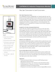
<strong>MEPC</strong> <strong>49</strong>/<strong>22</strong>/<strong>Add.2</strong><strong>ANNEX</strong> <strong>13</strong>Page 12Therefore the test rig must be so constructed as to include not only the 15 ppm Bilge Separator,but also the pumps, valves, pipes and fittings as shown in figure 2. It is to be so designed fortesting 15 ppm Bilge Separators with and without an integral supply pump.- For the testing of 15 ppm Bilge Separators having no integral pump, thecentrifugal pump “A” (figure 2) is used to feed the 15 ppm Bilge Separator withvalves 4 and 6 open, and valve 5 closed. The rate of flow from the centrifugalpump "A" is matched to the design throughput of the 15 ppm Bilge Separator bythe adjustment of the centrifugal pump’s discharge valve.- Where the 15 ppm Bilge Separator is fitted with an integral pump, the centrifugalpump "A" is not required.- A centrifugal pump "B" should be fitted to re-circulate the Test Fluid C in the tankto ensure that the Test Fluid C is maintained in a stable condition throughout thetesting. Re-circulation is not required for Test Fluids A and B.- To ensure a good mix of the Test Fluid and the water, a conditioning pipe asspecified in paragraph 1.2.5 of part 1 of this annex shall be fitted immediatelybefore the 15 ppm Bilge Separator.- Other valves, flow meters and sample points should be fitted to the test rig asshown in figure 2.- The pipe work should be designed for a maximum liquid velocity of3 metres/second.Water(clean water)RMG 35 DMATest fluid Test fluid(Test fluid"A"A) (Test fluid B)"B"Sample pointV2 V3 V8V1FMFlowmeterFMV4Test fluid"C"Sample pointV5PV6Centrifugal pumpACentrifugal pumpBPAuto. oildischargevalveV7Conditioning 15 ppmSeparated oilpipeBilgeSeparatorObservationwindowSample pointSample pointEffluentFigure 2 - Test rigI:\<strong>MEPC</strong>\<strong>49</strong>\<strong>22</strong>-ADD.2.DOC
<strong>MEPC</strong> <strong>49</strong>/<strong>22</strong>/<strong>Add.2</strong><strong>ANNEX</strong> <strong>13</strong>Page <strong>13</strong>1.2.3 The tests should be carried out with a supply rate equal to the full throughput for whichthe 15 ppm Bilge Separator is designed.1.2.4 Tests should be performed using three grades of test fluids.1 Test Fluid “A” which is a marine residual fuel oil in accordance with ISO 8217,type RMG 35 (density at 15 o C not less than 980 kg/m 3 ).2 Test Fluid "B" which is a marine distillate fuel oil in accordance with ISO 8217,type DMA (density at 15 o C not less than 830 kg/m 3 )..3 Test Fluid "C" which is a mixture of an oil-in-fresh water emulsion, in the ratiowhereby 1 kg of the mixture consists of- 947.8 g of fresh water;- 25.0 g of Test Fluid “A"- 25.0 g of Test Fluid “B”;- 0.5 g surfactant (sodium salt of dodecylbenzene sulfonic acid) in the dryform;- 1.7 g “iron oxides” (The term “iron oxide” is used to describe blackferrosoferric oxide (Fe 3 O 4 ) with a particle size distribution of which 90%is less than 10 microns, the remainder having a maximum particle size of100 microns);Note: Procedure for preparing Test Fluid C: (see example calculation) 1- Preparation(1) measure out 1.2 times the quantity of surfactant required for the“Test with Test Fluid C” as described in 1.2.11; and(2) mix it with fresh water and stir well in a small container (e.g., abeaker or bucket) to make a mixture (“Mixture D”) until thesurfactant has been thoroughly dissolved.- To make Test Fluid C in the test fluid tank (figure 3),(3) Fill test fluid tank with fresh water with a quantity 1.2 times thevolume of the total quantity of water in the test fluid “C” neededfor the test described in 1.2.11.1 Calculation of ingredients of Test Fluid” C” (Example: 2m 3 /h Bilge Separator).Operating period for the Test with Test Fluid “C” as per 1.2.11: 2.5 hours plus conditioning time (say 0.5hour) = 3 hoursNet volume needed for the Test: Volume of test water: 2m 3 x 3 hours = 6m 3Volume Test Fluid “C”: 6% of test water = 0.06 x 6m 3 = 0.36m 3Actual Volume to be prepared:Volume of Test Fluid “C” to be prepared: 1.2 times of the net volume of Test Fluid “C” = 1.2 x 0.36 = 0.432m 3Volume of fresh water in Test Fluid “C”: (947.8g/1000g) of Test Fluid “C” =0.9478 x 0.432 = 0.4094m 3Weight of Test Fluid “A”: (25g/1000g) of Test Fluid “C” =25/1000 x 0.432 x 1000 = 10.8kgWeight of Test Fluid “B”: (25g/1000g) of Test Fluid “C” = 25/1000 x 0.432 x 1000 = 10.8kgWeight of surfactant: (0.5g/1000g) of Test Fluid “C” = 0.5/1000 x 0.432 x 1000 = 0.216kgWeight of iron oxide: (1.7g/1000g) of Test Fluid “C”)=1.7/1000 x 0.432 x 1000 x 0.734kgI:\<strong>MEPC</strong>\<strong>49</strong>\<strong>22</strong>-ADD.2.DOC
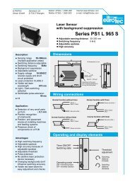
<strong>MEPC</strong> <strong>49</strong>/<strong>22</strong>/<strong>Add.2</strong><strong>ANNEX</strong> <strong>13</strong>Page 14(4) Operate centrifugal pump B running at a speed of not less than3,000 rpm (nominal) with a flow rate at which the volume of thetest fluid has been changed out at least once per minute.(5) Add “Mixture D” first, followed by oil and suspended solids (ironoxides) respectively, both 1.2 times of the required amounts, to thefresh water in the tank,(6) To establish a stable emulsion keep running the centrifugal pump Bfor one hour and confirm no oil floats on the surface of the testfluid.(7) After the one hour stated in paragraph (6) above keep running thecentrifugal pump B at reduced speed to approximately 10% oforiginal flow rate, until the end of the test.(1) Fresh water(2) Mixture Doilssuspended solidDOutletTo 15ppm bilgeseparatorHInletCentrifugal pumpBFigure 3 - Tank of Test Fluid “C”Note:(1) The tank should be of a cylindrical shape. The level of the water shouldbe:2D > H > 0.5D, when preparing Test Fluid “C”.(2) Outlet going to centrifugal pump B should be placed at as low a positionto the tank as possible.(3) Inlet to the tank should be fitted at the center of tank bottom so that themixture flows upward to obtain uniform and stable emulsion.If the 15 ppm Bilge Separator is fitted with heating facilities to allow the separated oil retained init to be discharged when the automatic discharge valve is activated, the Certificate of TypeApproval should be endorsed under the heading “Limiting Conditions Imposed” with thefollowing statement:“The 15 ppm separator is fitted with heating facility.”I:\<strong>MEPC</strong>\<strong>49</strong>\<strong>22</strong>-ADD.2.DOC
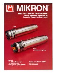
<strong>MEPC</strong> <strong>49</strong>/<strong>22</strong>/<strong>Add.2</strong><strong>ANNEX</strong> <strong>13</strong>Page 151.2.5 If the 15 ppm Bilge Separator includes an integrated feed pump, this 15 ppm BilgeSeparator should be tested with that pump supplying the required quantity of Test Fluid andwater to the 15 ppm Bilge Separator at its rated capacity.If the 15 ppm Bilge Separator is to be fed by the ship’s bilge pumps, then the unit will be testedby supplying the required quantity of Test Fluid and water mixture to the inlet of a centrifugalpump operating at not less that 1,000 rpm (see dotted line in figure 2). This pump should have adelivery capacity of not less than 1.1 times the rated capacity of the 15 ppm Bilge Separator atthe delivery pressure required for the test. The variation in Test Fluid/water ratio will beobtained by adjusting valves on the Test Fluid and water suction pipes adjacent to the pumpsuction, and the flow rate of Test Fluid and water or the Test Fluid content of the supply to the15 ppm Bilge Separator should be monitored. If a centrifugal pump is used, the excess pumpcapacity should be controlled by a throttle valve on the discharge side of the pump.In all cases, to ensure uniform conditions, the piping arrangements immediately prior tothe 15 ppm Bilge Separator should be such that the influent to the 15 ppm Bilge Separator shouldhave a Reynolds Number of not less than 10,000 as calculated in fresh water, a liquid velocity ofnot less than 1 metre per second and the length of the supply pipe from the point of Test Fluidinjection to the 15 ppm Bilge Separator should have a length not less than 20 times its diameter.A mixture inlet sampling point and a thermometer pocket should be provided near the 15 ppmBilge Separator inlet and an outlet sampling point and observation window should be providedon the discharge pipe.1.2.6 In order to approach isokinetic sampling – i.e. the sample enters the sampling pipe atstream velocity – the sampling arrangement should be as shown in figure 4 and, if a cock isfitted, free flow should be effected for at least one minute before any sample is taken. Thesampling points should be in pipes running vertically.Figure 4 – Diagram of sampling arrangementsA Distance A, not greater than 400 mmB Distance B, sufficient to insert sampling bottleC Dimension C, straight length should not be less than 60 mmD Dimension D, pipe thickness should not be greater than 2mmE Detail E, chisel-edged chamfer (30 o )I:\<strong>MEPC</strong>\<strong>49</strong>\<strong>22</strong>-ADD.2.DOC
<strong>MEPC</strong> <strong>49</strong>/<strong>22</strong>/<strong>Add.2</strong><strong>ANNEX</strong> <strong>13</strong>Page 161.2.7 In the case of the 15 ppm Bilge Separator depending essentially on gravity, the feed to thesystem of the test water and Test Fluid mixture should be maintained at a temperature notgreater than 40 o C, and heating and cooling coils should be provided where necessary. The watershall have a density of not more than 1,015 at 20 o C. In other forms of separation where thedependence of separation efficiency on temperature is not established, tests should be carried outover a range of influent temperatures representing the normal shipboard operating range of 10 o Cto 40 o C or should be taken at a temperature in this range where the separation efficiency isknown to be worst.1.2.8 In those cases where, for the 15 ppm Bilge Separator, it is necessary to heat water up to agiven temperature and to supply heat to maintain that temperature, the tests should be carried outat the given temperature.1.2.9 The tests with Test Fluid “A” should be carried out as follows:.1 To ensure that the 15 ppm Bilge Separator commences the test with the oil sectionfull of Test Fluid and with the supply line impregnated with Test Fluid, the15 ppm Bilge Separator should, after filling with water (density at 20 o C not morethan 1,015) and while in the operating condition, be fed with pure Test Fluid fornot less than 5 min..2 The 15 ppm Bilge Separator should be fed with a mixture composed of between5,000 and 10,000ppm of Test Fluid in water until steady conditions have beenestablished. Steady conditions are assumed to be the conditions established afterpumping through the 15 ppm Bilge Separator a quantity of Test Fluid/watermixture not less than twice the volume of the 15 ppm Bilge Separator. The testshould then proceed for 30 min. Samples should be taken at the effluent outlet at10 min and 20 min from the start of this period. At the end of this test, an air cockshould be opened on the suction side of the pump and, if necessary, the oil andwater valves should be slowly closed together, and a sample taken at the effluentdischarge as the flow ceases (this point can be checked from the observationwindow)..3 A test identical to that described in 1.2.9.2, including the opening of the air cock,should be carried out with a mixture composed of approximately 25% * Test Fluidand 75% * water..4 The 15 ppm Bilge Separator should be fed with 100% * of Test Fluid for at least5 min during which time the observation window should be checked for any oildischarge. Sufficient Test Fluid should be fed into the 15 ppm Bilge Separator tooperate the automatic oil discharge valve. After the operation of the oil dischargevalve, the test should be continued for 5 min using a 100% * Test Fluid supply inorder to check the sufficiency of the oil discharge system..5 The 15 ppm Bilge Separator should be fed with water (density at 20 o C not morethan 1,015) for 15 min. Samples of the separated water effluent are taken at thebeginning of the test and after the first 10 min..6 A test lasting a minimum of 2 h should be carried out to check that the 15 ppmBilge Separator will operate continuously and automatically. This trial should usea cycle varying progressively from water to oily mixture with approximately 25% **Percentage of volume.I:\<strong>MEPC</strong>\<strong>49</strong>\<strong>22</strong>-ADD.2.DOC
<strong>MEPC</strong> <strong>49</strong>/<strong>22</strong>/<strong>Add.2</strong><strong>ANNEX</strong> <strong>13</strong>Page 17Test Fluid content and back to water every 15 minutes, and should test adequatelyany automatic device which is fitted. The whole test sequence should beperformed as a continuous programme. At the end of the test, while the 15 ppmBilge Separator is being fed with 25% * Test Fluid, a water effluent sample shouldbe taken for analysis.1.2.10 The tests with Test Fluid “B” should be carried out as follows:.1 The 15 ppm Bilge Separator should be fed with a mixture composed of between5,000 and 10,000ppm of Test Fluid in water until steady conditions have beenestablished. Steady conditions are assumed to be the conditions established afterpumping through the 15 ppm Bilge Separator a quantity of Test Fluid/watermixture not less than twice the volume of the 15 ppm Bilge Separator. The testshould then proceed for 30 min. Samples should be taken at the effluent outlet at10 min and 20 min from the start of this period. At the end of this test, an air cockshould be opened on the suction side of the pump and, if necessary, the oil andwater valves should be slowly closed together, and a sample taken at the effluentdischarge as the flow ceases (this point can be checked from the observationwindow)..2 A test identical to that described in 1.2.10.1, including the opening of the air cock,should be carried out with a mixture composed of approximately 25% * Test Fluidand 75% * water.1.2.11 The tests with Test Fluid “C” should be carried out as follows:.1 The 15 ppm Bilge Separator should be fed with a mixture composed of 6% TestFluid “C” and 94% water to have emulsified oil content of 3,000 ppm in the testwater until steady conditions have been established. Steady conditions areassumed to be the conditions established after pumping through the 15 ppm BilgeSeparator a quantity of Test Fluid “C”/water mixture not less than twice thevolume of the 15 ppm Bilge Separator..2 The test should then proceed for 2.5 h. Samples should be taken at the effluentoutlet at 50 minutes and 100 minutes after conditioning. At the end of this test, anair cock should be opened on the suction side of the pump and, if necessary, theTest Fluid "C” and water valves should be slowly closed together, and a sampletaken at the effluent discharge as the flow ceases (this point can be checked fromthe observation window).1.2.12 Sampling should be carried out as shown in figure 4 so that the sample taken will suitablyrepresent the fluid issuing from the effluent outlet of the 15 ppm Bilge Separator.1.2.<strong>13</strong> Samples should be taken in accordance with ISO 9377-2:2000. The sample is to beextracted on the same day of collection, and be sealed and labelled in the presence of arepresentative of the national authority and arrangements should be made for analysis as soon aspossible and in any case within seven days provided the samples are being kept between 2ºC and6ºC at laboratories approved by the Administration.1.2.14 The oil content of the samples should be determined in accordance with part 4 of theannex.* Percentage of volume.I:\<strong>MEPC</strong>\<strong>49</strong>\<strong>22</strong>-ADD.2.DOC
<strong>MEPC</strong> <strong>49</strong>/<strong>22</strong>/<strong>Add.2</strong><strong>ANNEX</strong> <strong>13</strong>Page 181.2.15 When accurate and reliable oil content meters are fitted at inlet and outlet of the 15 ppmBilge Separator, one sample at inlet and outlet taken during each test will be considered sufficientif they verify, to within + 10%, the meter readings noted at the same instant.1.2.16 In the presentation of the results, the following data testing methods and readings shouldbe reported:.1 Properties of test fluids A and B:I:\<strong>MEPC</strong>\<strong>49</strong>\<strong>22</strong>-ADD.2.DOC- density at 15 o C;- kinematic viscosity (centistokes @ 100 o C /40 o C);- flashpoint;- ash; and- water content;.2 Properties of test fluid C:- type of surfactant;- particle size percentage of the non soluble suspended solids; and- surfactant and iron oxide quality verification;.3 Properties of the water in the water tank:- density of water at 20ºC; and- details of any solid matter present;.4 Temperature at the inlet to the 15 ppm Bilge Separator;.5 A diagram of the test rig;.6 A diagram of the sampling arrangement; and.7 The method used in analysis of all samples taken and the results thereof, togetherwith oil content meter readings, where appropriate.PART 2 - TEST AND PERFORMANCE SPECIFICATIONS FOR TYPE APPROVAL OF15 PPM BILGE ALARMS2.1 General2.1.1 These Test and Performance Specifications relate to 15 ppm Bilge Alarms. In addition,the electrical and electronic section of these systems should be in accordance with theSpecifications for Environmental Testing contained in part 3 of this annex.2.1.2 The 15 ppm Bilge Alarm being tested should comply with all the relevant requirements ofthe technical specifications contained in section 4.2 of these Guidelines and Specifications.
<strong>MEPC</strong> <strong>49</strong>/<strong>22</strong>/<strong>Add.2</strong><strong>ANNEX</strong> <strong>13</strong>Page 192.2 Test specifications2.2.1 For a 15 ppm Bilge Alarm, the accuracy should be within + 5 ppm. The accuracy of a15 ppm Bilge Alarm should remain within the above limits despite the presence of contaminantsother than oil, and the power supply varying by 10% from the design value – i.e. in respect ofelectricity, compressed air, etc.2.2.2 The sampling arrangement for the test rig should be such that a representativehomogeneous sample is obtained under all conditions of operation and under all operationalproportions of oil content. The sample should be obtained from the full flow through the 15 ppmBilge Alarm, but when this is impracticable the sampling arrangements shown in figure 4 inpart 1 should be used. Special care should be given to this stage of the process and the validity ofthe resultant findings.2.2.3 During the various tests, the response time of the 15 ppm Bilge Alarm should be checkedand it should be noted whether alarms operate adequately when a pre-stated threshold isexceeded.2.2.4 A diagrammatic arrangement of a test facility for evaluating the performance of the15 ppm Bilge Alarm is given in figure 5. The accuracy of the 15 ppm Bilge Alarm will bedetermined by comparing its readings against a known flow of Test Fluid injected into a knownflow of water. The grab samples taken will be analysed in a laboratory by the methods specifiedin part 4 of this annex. The results of the laboratory analysis will be used for correction and toindicate sampling and test equipment variability. The water flow rate will be adjusted so that theentire Test Fluid-water flow passes through the 15 ppm Bilge Alarm, except the intermittent grabsample stream. Special care should be given to keep, continuously, a constant Test Fluid contentin the water that flows into the 15 ppm Bilge Alarm. The metering pumps should be adjusted todeliver a nearly continuous quantity of Test Fluid. If Test Fluid injection becomes intermittent atlow concentrations, the Test Fluid may be pre-mixed with water to provide continuous flow. TheTest Fluid injection point should be immediately up-stream of the 15 ppm Bilge Alarm inlet tominimize time lags.Calibration test2.2.5 The 15 ppm Bilge Alarm will be calibrated and zeroed as per the manufacturer’sinstructions. It will then be tested with the three test fluids "A", "B" and "C", as specified inparagraph 1.2.4 of part 1 of the annex, at the following oil concentrations in parts per million: 0,15, and at the full scale of the meter. Each concentration test will last for 15 min. Followingeach concentration test, the 15 ppm Alarm will be run on oil-free water for 15 min and thereading noted. If it proves necessary to re-zero or re-calibrate the 15 ppm Bilge Alarm duringthis test, this fact will be noted.I:\<strong>MEPC</strong>\<strong>49</strong>\<strong>22</strong>-ADD.2.DOC
<strong>MEPC</strong> <strong>49</strong>/<strong>22</strong>/<strong>Add.2</strong><strong>ANNEX</strong> <strong>13</strong>Page 20Contaminant and colour testFigure 5 - Diagrammatic arrangements of test facilities2.2.6 The 15 ppm Bilge Alarm should undergo contaminant and colour tests as follows:.1 the 15 ppm Bilge Alarm should be run on a mixture of clean water and 10 ppmTest Fluid “B” and reading noted;.2 the water supply should be changed from 10 ppm Test Fluid “B” and clean waterto 10 ppm Test Fluid “B” and water contaminated with iron oxide in aconcentration of 10 ppm;.3 any shift in the 15 ppm Bilge Alarm reading should be noted. The reading shouldbe within the accuracy limits specified in paragraph 2.2.1;.4 the procedure specified in .2 and .3 above should be repeated with iron oxideconcentrations of 50 ppm and 100 ppm respectively;.5 the 15 ppm Bilge Alarm should be run on a mixture of clean water and 10 ppmTest Fluid “B” and its reading noted;.6 the water supply should be changed from clean water to very salt water (a solutionof 6% common salt with clean water);.7 any shift in the 15 ppm Bilge Alarm reading should be noted. The reading shouldbe within the accuracy limits specified in paragraph 2.2.1; and.8 sufficient water should be available in the mixing tank to ensure an effective testof not less than 15 min.I:\<strong>MEPC</strong>\<strong>49</strong>\<strong>22</strong>-ADD.2.DOC
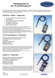
<strong>MEPC</strong> <strong>49</strong>/<strong>22</strong>/<strong>Add.2</strong><strong>ANNEX</strong> <strong>13</strong>Page 21Sample pressure or flow test2.2.7 The 15 ppm Bilge Alarm should be run on a 15 ppm Test Fluid “B” sample. The waterpressure or flow rate of the mixture should be adjusted from one half normal, normal and twicenormal. Any effect of these changes on the 15 ppm Bilge Alarm ppm display reading should benoted and recorded on the Certificate. This test may require modification for 15 ppm BilgeAlarms with flow or pressure regulators or 15 ppm Bilge Alarms designed to discharge into anambient pressure sump.Shut off tests2.2.8 The 15 ppm Bilge Alarm should be run on a 15 ppm Test Fluid “B” sample. The waterand Test Fluid injection pumps should be shut off. The 15 ppm Bilge Alarm will be left turnedon with no other changes made. After 8 hours, the water and Test Fluid injection pump shouldbe turned on and set to provide the mixture of 15 ppm. The 15 ppm Bilge Alarm ppm displayreadings before and after each test and any damage to the 15 ppm Alarm should be noted andrecorded on the Certificate.Utilities supply variation test2.2.9 If the 15 ppm Bilge Alarm requires any utilities besides electricity, it should be testedwith these utilities at 110% and 90% of the design figures.Calibration and zero drift test2.2.10 The 15 ppm Bilge Alarm should be calibrated and zeroed. A 15 ppm Test Fluid “B”sample will run through the 15 ppm Bilge Alarm for eight hours and any calibration drift noted.Following this, the 15 ppm Bilge Alarm should run on oil-free water and any zero drift noted andrecorded on the Certificate. During this test grab samples should be taken 0, 2, 4, 6, and 8 hoursinto the test schedule to verify any calibration drift.Response time test2.2.11 The response time is to be taken for the 15 ppm Bilge Alarm to give an alarm at 15 ppmoil concentration after the supply to the 15 ppm Bilge Alarm is changed from clean water to oilywater having a concentration of more than 15 ppm oil.2.2.12 A specification of the instrument concerned and a diagrammatic presentation of the testarrangements should be provided and the following data should be reported..1 types and properties of Test Fluids used in the tests (refer to part 1,paragraphs 1.2.4 and 1.2.16 of this annex);.2 details of contaminants used, in the form, for example, of a supplier’s certificateor laboratory test protocol; and.3 results of tests and analysis of grab samples.I:\<strong>MEPC</strong>\<strong>49</strong>\<strong>22</strong>-ADD.2.DOC
<strong>MEPC</strong> <strong>49</strong>/<strong>22</strong>/<strong>Add.2</strong><strong>ANNEX</strong> <strong>13</strong>Page <strong>22</strong>PART 3 - SPECIFICATIONS FOR ENVIRONMENTAL TESTING FOR TYPEAPPROVAL OF POLLUTION PREVENTION EQUIPMENT3.1 GeneralThe specifications for environmental testing for type approval relate to the electrical andelectronic sections of:.1 15 ppm Bilge Separator; and.2 15 ppm Bilge Alarm.The above-mentioned items, hereafter referred to as "equipment", when tested should complywith all the relevant requirements contained in section 5 of these Guidelines and Specifications.3.2 Test specifications3.2.1 Testing requirementsThe electrical and electronic sections of the equipment in the standard production configurationshould be subjected to the programme of environmental tests set out in this Specification at alaboratory approved for the purpose by the Administration or by the competent authority of themanufacturer’s home country. A copy of the environmental test document, in a format similar tothat specified in section 2 of part 5 of this annex, should be submitted to the Administration bythe manufacturer, together with the application for type approval.3.2.2 Test specification detailsEquipment should operate satisfactorily on completion of each of the following environmentaltests:.1 Vibration tests:.1.1 a search should be made for resonance over the following range offrequency and amplitude of acceleration:.1.1.1 2 to <strong>13</strong>.2 Hz with an amplitude of + 1mm; and.1.1.2 <strong>13</strong>.2 to 80 Hz with an acceleration of + 0.7 g.This search should be made in each of the three planes at a rate sufficientlylow to permit detection of resonance;.1.2 the equipment should be vibrated in the planes at each major resonantfrequency for a period of 2 hours;.1.3 if there is no resonant frequency, the equipment should be vibrated in eachof the planes at 30 Hz with an acceleration of + 0.7 g for a period of2 hours;.1.4 after completion of the tests specified in .1.2 or .1.3 of this paragraph asearch should again be made for resonance and there should be nosignificant change in the vibration pattern.I:\<strong>MEPC</strong>\<strong>49</strong>\<strong>22</strong>-ADD.2.DOC
<strong>MEPC</strong> <strong>49</strong>/<strong>22</strong>/<strong>Add.2</strong><strong>ANNEX</strong> <strong>13</strong>Page 23.2 Temperature tests:.2.1 equipment that may be installed in an enclosed space that isenvironmentally controlled, including an engine-room, should besubjected, for a period of not less than 2 h, to:.2.1.1 a low temperature test at 0°C; and.2.1.2 a high temperature test at 55°C..3 Humidity tests:At the end of each of the tests referred to, the equipment should beswitched on and it should function normally under the test conditions.Equipment should be left switched off for a period of 2 h at a temperature of 55ºCin an atmosphere with a relative humidity of 90%. At the end of this period theequipment should be switched on and should operate satisfactorily for 1 hour;.4 Inclination test:Equipment should operate satisfactorily at angles of inclination up to <strong>22</strong>.5º in anyplane from the normal operating position;.5 Reliability of electrical and electronic equipment:The electrical and electronic components of the equipment should be of a qualityguaranteed by the manufacturer and suitable for their intended purpose.PART 4 – METHOD FOR DETERMINATION OF OIL CONTENTScope and applicationThe International Standard ISO 9377-2:2000 “Water quality - Determination of hydrocarbon oilindex – Part 2: Method using solvent extraction and gas chromatography” specifies a method forthe sampling and subsequent determination of the hydrocarbon oil index in water using solventextraction and gas chromatography. This method should be used for the determination of oilcontent requirements outlined in these Guidelines and SpecificationPART 5 – DOCUMENTATION OF APPROVAL5.1 Certificate of Type Approval for pollution prevention equipment.5.1.1 Satisfactory compliance with all the test requirements enumerated in parts 1 and 2 of thisannex should be shown in the Certificate of Type Approval issued by the Administration in theformat specified in paragraph 5.1.2 below. An Administration may issue a Certificate of TypeApproval based on separate testing or on testing already carried out under supervision by anotherAdministration.I:\<strong>MEPC</strong>\<strong>49</strong>\<strong>22</strong>-ADD.2.DOC
<strong>MEPC</strong> <strong>49</strong>/<strong>22</strong>/<strong>Add.2</strong><strong>ANNEX</strong> <strong>13</strong>Page 245.1.2 A Certificate of Type Approval should be in the format shown in appendix 1 or 2 to thisannex. The Certificate should identify the type and model of the pollution prevention equipmentto which it applies and identify equipment assembly drawings, duly dated. Each drawing shouldbear the model specification numbers or equivalent identification details. The Certificate shouldinclude the full performance test protocol on which it is based. If a Certificate of Type Approvalis issued by an Administration based on a Certificate previously issued by anotherAdministration, the Certificate should identify the Administration which conducted the tests onthe pollution prevention equipment and a copy of the original test results should be attached to it.5.2 Format of environmental test protocol5.2.1 Satisfactory compliance with the environmental tests laid down in these Guidelines andSpecifications, where applicable, should be shown on the environmental test protocol issued bythe testing laboratory. The protocol should include at least the following details..1 identification of the equipment by type and drawing number, duly dated; and.2 a statement of the tests conducted on the equipment, including the results thereof.5.2.2 The environmental test protocol should be endorsed by either the Administration or acompetent authority of the manufacturer’s home country to confirm that the laboratory isapproved to conduct such tests. The protocol should also be signed and dated by the person incharge of the laboratory.I:\<strong>MEPC</strong>\<strong>49</strong>\<strong>22</strong>-ADD.2.DOC
<strong>MEPC</strong> <strong>49</strong>/<strong>22</strong>/<strong>Add.2</strong><strong>ANNEX</strong> <strong>13</strong>Page 25BadgeorCipherAPPENDIX 1NAME OF ADMINISTRATIONCERTIFICATE OF TYPE APPROVAL FOR 15PPM BILGE SEPARATORThis is to certify that the 15 ppm Bilge Separator listed below has been examined and tested in accordancewith the requirements of the specifications contained in part 1 of the annex to the guidelines andspecifications contained in IMO resolution <strong>MEPC</strong>.107(<strong>49</strong>). This certificate is valid only for 15 ppm BilgeSeparator referred to below.15 ppm Bilge Separator supplied by………………………………….………………………………………………………………………….…Under type and model designation ……….…………………………………………………………...…….and incorporating:* 15 ppm Bilge Separator manufactured byto specification/assembly drawing No …………………..date* Coalescer manufactured byto specification/assembly drawing No ……………………………………………………………* Filters manufactured by other means…………………………………………………………….to specification/assembly drawing No* Other means ………………………………………………to specification/assembly drawing No……………………………………………..Control equipment manufactured byto specification/assembly drawing No .……………………Supply pump capacity…………………m 3 /h…….….Motor kWrating……………………kW……….…Maximum throughput of system …………………………………. m 3 /h ..……If integral feed pump is not fitted state method proposed for ensuring maximum throughput of system isnot exceeded………………………………………………………………………………………………….A copy of this Certificate should be carried aboard a vessel fitted with this Separator at all times.Limiting conditions imposed………………..…………………………………………………….Test date and results attached in the appendix.Official stampSigned…………………………………….…………………..……Administration of …..……………………………………………..Date this …………… day of …………………………………20..______________*Delete as appropriate.I:\<strong>MEPC</strong>\<strong>49</strong>\<strong>22</strong>-ADD.2.DOC
<strong>MEPC</strong> <strong>49</strong>/<strong>22</strong>/<strong>Add.2</strong><strong>ANNEX</strong> <strong>13</strong>Page 26APPENDIXTEST DATA AND RESULTS OF TESTS CONDUCTED ON A 15 PPM BILGESEPARATOR IN ACCORDANCE WITH PART 1 OF THE<strong>ANNEX</strong> TO THE GUIDELINES AND SPECIFICATIONS CONTAINEDIN IMO <strong>RESOLUTION</strong> <strong>MEPC</strong>.107(<strong>49</strong>)15 ppm Bilge Separator submitted by………………………………………………………………………………………………………Test location ………………………………………………………………………………………..Method of sample analysis ...………………………………………………………………………........………………………………………………………………………………………………….…………...………………………………………………………………………………………….………………………………………………………………………………………………………Samples analysed by ….……………………………………………………………………………Environmental testing of the electrical and electronic sections of the 15 ppm Bilge Separator hasbeen carried out in accordance with part 3 of the annex to the guidelines and specificationscontained in IMO resolution <strong>MEPC</strong>.107(<strong>49</strong>). The equipment functioned satisfactorily oncompletion of each test specified on the environmental test protocol.………………………………………………………………………………………………………………………………………………………………………………………………………………………………………………………………………………………………………………………………………………………………………………………………………………………………I:\<strong>MEPC</strong>\<strong>49</strong>\<strong>22</strong>-ADD.2.DOC
<strong>MEPC</strong> <strong>49</strong>/<strong>22</strong>/<strong>Add.2</strong><strong>ANNEX</strong> <strong>13</strong>Page 27Test fluid “A”Density at 15ºCViscosity Centistokes at 100ºCFlashpoint ºCAsh content %Water content at start of test %Test fluid “B”Density at 15ºCViscosity Centistokes at 40ºCFlashpoint ºCAsh content %Water content at start of test %Test fluid “C”Test waterTest temperaturesSurfactant - documentary evidence*Iron oxides - documentary evidence*Density at 20ºCSolid matter presentAmbient ºCTest fluid “A” ºCTest fluid “B” ºCTest fluid “C” ºCTest water ºCDiagram of test rig attachedDiagram of sampling arrangement attached______________* Certificate or laboratory analysis.I:\<strong>MEPC</strong>\<strong>49</strong>\<strong>22</strong>-ADD.2.DOC
<strong>MEPC</strong> <strong>49</strong>/<strong>22</strong>/<strong>Add.2</strong><strong>ANNEX</strong> <strong>13</strong>Page 28TEST RESULTS (IN PPM) AND TEST PROCEDURESTest Fluid A1 2 3 4 5 6(1.2.9.1) (1.2.9.2) (1.2.9.3) (1.2.9.4) (1.2.9.5) (1.2.9.6)Efficiency testEfficiency test100% Condi- 0.5 - 1 % oil Condi- 25 % oil 100%oil tioning tioning oilOil free25% oil every 15 min.not Vm≧ 30 Vm≧ not 15 15 Timeless 2Ve 2Ve 30 less 120 (mins)than 5 than 5Air cock openflow ceasesAir cock openflow ceases147 89Test sample 9(taken at the end of auto test, paragraphVe - volume of equipment 2 35 6 Test sample 9 (taken at the end of auto test, paragraph1.2.9.6 Annex to resolution ……..)Vm - quantity of oil/water mixture of the Annex to resolution……)Influent1 2 3 4 5 6 7 8 9EffluentTest Fluid BTest fluid C7 89(1.2.10.1) (1.2.10.2)(1.2.11)Efficiency testEfficiency testEfficiency testCondi- 0.5 - 1 % oil Condi- 25 % oilConditioning6% Test Fluid CtioningtioningVm≧ 30 Vm≧ 30 Time Vm≧ 150 Time2Ve 2Ve (mins) 2Ve (mins)InfluentEffluent1011Air cock openflow ceases12<strong>13</strong>14Air cock openflow ceases151617Air cock openflow ceases10 11 12 <strong>13</strong> 14 15 16 17 181 – 9 steps refer to paragraph 1 - 18 points where samples to be taken18Signed ………………………………………. Date ………………………………… Official stamp(Official stamp or equivalent identification and the date of approval to be placed on all pages of the testprotocol.)I:\<strong>MEPC</strong>\<strong>49</strong>\<strong>22</strong>-ADD.2.DOC
<strong>MEPC</strong> <strong>49</strong>/<strong>22</strong>/<strong>Add.2</strong><strong>ANNEX</strong> <strong>13</strong>Page 29APPENDIX 2BadgeorCipherNAME OF ADMINISTRATIONCERTIFICATE OF TYPE APPROVAL FOR 15 PPM BILGE ALARMThis is to certify that the 15 ppm Bilge Alarm, comprising the equipment listed below, has beenexamined and tested in accordance with the requirements of the specifications contained in part 2of the annex to the Guidelines and Specifications contained in IMO resolution <strong>MEPC</strong>.107(<strong>49</strong>).This Certificate is valid only for the 15 ppm Bilge Alarm referred to below.15 ppm Bilge Alarm supplied by …………………………………………………………………..under type and model designation ………………………………………………………………….and incorporating:15 ppm Bilge Alarm analysing unit manufactured by ………………..……………………………to specification/assembly drawing No. ……………………………… date ..………………..……Electronic section of 15 ppm Bilge Alarm manufactured by ………………..………………….....to specification/assembly drawing No. ……………………………… date………………………..* Sample feed pump manufactured by ...……………………………………………………………to specification/assembly drawing No. ……………………………… date…..……………………* Sample conditioning unit manufactured by ………………………………………………………to specification/assembly drawing No. ……………………………… date………………………..The 15 ppm Bilge Alarm is acceptable for use in accordance with regulation 16(5).A copy of this Certificate should be carried aboard a vessel fitted with this 15 ppm Bilge Alarmat all times.Test data and results attached as appendix.Official stampSigned:.……………………………………………..Administration of ………………………………….Dated this …………….. day of …………….. 20.…* Delete as appropriate.I:\<strong>MEPC</strong>\<strong>49</strong>\<strong>22</strong>-ADD.2.DOC
<strong>MEPC</strong> <strong>49</strong>/<strong>22</strong>/<strong>Add.2</strong><strong>ANNEX</strong> <strong>13</strong>Page 30APPENDIXTEST DATA AND RESULTS OF TESTS CONDUCTED ON A15 PPM BILGE ALARM IN ACCORDANCE WITH PART 2 OFTHE <strong>ANNEX</strong> TO THE GUIDELINES AND SPECIFICATIONSCONTAINED IMO <strong>RESOLUTION</strong> <strong>MEPC</strong>.107(<strong>49</strong>)15 ppm Bilge Alarm submitted by ……………….……………………………………………….Test location ……………………………………………………………………………………….Method of sample analysis .………………………………………………………………………..Samples analysed .………………………………………………………………………………….Environmental testing of the electronic section of the 15 ppm Bilge Alarm has been carried out inaccordance with part 3 of the annex to the Guidelines and Specifications contained in IMOresolution <strong>MEPC</strong>.107(<strong>49</strong>). The equipment functioned satisfactorily on completion of each testspecified on the environmental test protocol.………………………………………………………………………………………………………………………………………………………………………………………………………………………………………………………………………………………………………………………………………………………………………………………………………………………………I:\<strong>MEPC</strong>\<strong>49</strong>\<strong>22</strong>-ADD.2.DOC
<strong>MEPC</strong> <strong>49</strong>/<strong>22</strong>/<strong>Add.2</strong><strong>ANNEX</strong> <strong>13</strong>Page 31CALIBRATION TEST AND RESPONSE TIMETest FluidA B CMeasuredGrabsampleMeasuredGrabsampleMeasuredGrabsample0 ppm15 ppmFull scale (ppm)Water Temperature ºC ºC ºCRe-zero Yes/No Yes/No Yes/NoRecalibrate Yes/No Yes/No Yes/NoResponse Time sec sec secCONTAMINANT(S) AND COLOUR TESTNon-oil particulate matterMeter reading shift with ppmnon-oil particulate contaminantsand with very salt water .Oil Content Meter ReadingClean water and 10 ppm Test Fluid “B”ppmVery salt waterIron OxideIron OxideIron Oxide10 ppm50 ppm100 ppmppmppmppmppmI:\<strong>MEPC</strong>\<strong>49</strong>\<strong>22</strong>-ADD.2.DOC
<strong>MEPC</strong> <strong>49</strong>/<strong>22</strong>/<strong>Add.2</strong><strong>ANNEX</strong> <strong>13</strong>Page 32SAMPLE PRESSURE OR FLOW TEST15 ppm Bilge Alarm reading shift at 50% of normal … ppm15 ppm Bilge Alarm reading shift at 200% of normal … ppmDeviations from this test should be stated if necessarySHUT OFF TEST15 ppm Bilge Alarm reading before shut-off … ppm15 ppm Bilge Alarm reading after start-up(minimum dry period 8 hours)… ppmDamage to 15 ppm Bilge Alarm as follows:…………………………………………………………………………………………………………………………………………………….………………………………………………………………………….………………………………………………………………………….UTILITIES SUPPLY VARIATION TEST110% voltage effects ……………………………..90% voltage effects ……………………………..110% air pressure effects ……………………………..90% air pressure effects ……………………………..110% hydraulic pressure effects ……………………………..90% hydraulic pressure effects ……………………………..OTHER COMMENTS………………………………………………………………………………………………………………………………………………………………………………………………………………………………………………………………………………………………………………………………………………………………………………………………………………………………………………………………………………………………………………………………………………………………………………………………………………………………………………I:\<strong>MEPC</strong>\<strong>49</strong>\<strong>22</strong>-ADD.2.DOC
<strong>MEPC</strong> <strong>49</strong>/<strong>22</strong>/<strong>Add.2</strong><strong>ANNEX</strong> <strong>13</strong>Page 33CALIBRATION AND ZERO DRIFT TESTCalibration driftZero drift… ppm… ppmSigned……………………………………Dated…………………………………..Official stamp(Official stamp or equivalent identification and the date of approval to be placed on all pages ofthe test protocol)***I:\<strong>MEPC</strong>\<strong>49</strong>\<strong>22</strong>-ADD.2.DOC