Process Modelling and Simulation for GaAs P-HEMT ... - CS Mantech
Process Modelling and Simulation for GaAs P-HEMT ... - CS Mantech
Process Modelling and Simulation for GaAs P-HEMT ... - CS Mantech

You also want an ePaper? Increase the reach of your titles
YUMPU automatically turns print PDFs into web optimized ePapers that Google loves.
Copyright © 2001, <strong>GaAs</strong> MANTECH, Inc.<strong>Process</strong> <strong>Modelling</strong> <strong>and</strong> <strong>Simulation</strong> <strong>for</strong> <strong>GaAs</strong> P-<strong>HEMT</strong>Gate Improvement <strong>and</strong> ControlS K Jones, D J Bazley, D R Brambley, P A Claxton, I R Cleverley, I Davies, R A Davies,C Hill, W A Phillips, N M Shorrocks, M Stott, K Vanner, R H Wallis, D J WarnerCaswell Technology, Marconi Caswell Ltd, Caswell, Towcester, Northants NN12 8EQ, UKe-mail: stephen.k.jones@marconi.com, phone: +44 (0)1327 356309ABSTRACTThe drive to increase yield <strong>and</strong> volume of <strong>GaAs</strong>manufacturing has motivated the increased use of process<strong>and</strong> device modelling to underst<strong>and</strong> <strong>and</strong> control sources ofprocess variation <strong>and</strong> to improve device design <strong>for</strong> flexiblemanufacturing. Adapting tools <strong>and</strong> techniques developed<strong>for</strong> VLSI silicon, we have implemented a Technology CADprocedure <strong>for</strong> evaluation of process <strong>and</strong> device design.The purpose of this paper is to present results on how thisprocedure is being used to support our 150mm foundryupgrade, with specific focus on the L g=0.2 micronPseudomorphic <strong>HEMT</strong> process.INTRODUCTION<strong>Process</strong> <strong>and</strong> device modelling <strong>and</strong> simulation within theframework of Technology CAD (TCAD) is widely used insemiconductor silicon development <strong>and</strong> manufacturing toimprove time-to-market, reduce cost <strong>and</strong> improve process <strong>and</strong>device design. Indeed, the recently published update to theinternational roadmap <strong>for</strong> semiconductors [1] declared anactual cost-reduction due to TCAD of 20% in 1999, <strong>and</strong><strong>for</strong>ecasts 35% <strong>for</strong> 2005. Although device modelling is widelyreported in the III-V industry, see <strong>for</strong> example, [2], processmodelling is, as yet, rather scarce. In this paper, we willshow an example of how process modelling can be used togain insight into technology options <strong>for</strong> gate processing in adouble recess pseudomorphic <strong>GaAs</strong> <strong>HEMT</strong> (P<strong>HEMT</strong>)process, within a 150mm process line.With the upgrade from 3 inch to 150mm <strong>GaAs</strong> waferprocessing the issue of e-beam lithography wafer throughputbecomes more critical, with photolithography potentially anattractive option. We have assessed three possible options <strong>for</strong>0.2 micron gate processing within simulation: (A) pure directwritee-beam lithography based upon our existingconventional tri-layer resist process [3]; (B) a mixed e-beam<strong>and</strong> optical lithography process (e.g. as in [4]); <strong>and</strong> (C) pureoptical lithography using an i-line stepper (e.g. as in [5]). Theprocess modelling contribution to this has been to assessprocess complexity <strong>and</strong> sensitivity, in particular the impact ongate CD control, <strong>and</strong> to provide quantitative guidelines <strong>and</strong>recommendations <strong>for</strong> initial process studies.MODELLING AND SIMULATIONWe have adapted commercial software tools used withinthe silicon industry <strong>for</strong> application to our <strong>GaAs</strong> P<strong>HEMT</strong>technology [6]. Typically process modelling is per<strong>for</strong>med ina 2D vertical cross-section of the device, on the scale of thedevice (~10 micron) <strong>and</strong> aims to predict the device geometry,layer structure <strong>and</strong> topography, <strong>and</strong> doping distribution. Inthis work, we focus upon the device geometry <strong>and</strong> topographymodelled through sequential deposition <strong>and</strong> etch stages. Thespecific processes modelled are metal evaporation, (PE)CVDnitride deposition, wet <strong>and</strong> dry (plasma) etch. The metalevaporation model has a narrow angular distribution ofvapour flux impinging on the wafer surface with high stickingcoefficient, giving rise to shadowing effects. In addition, wemodel a small component of isotropic deposition to simulatesurface migration <strong>and</strong>/or re-emission. Nitride deposition ismodelled as con<strong>for</strong>mal (reactants have a low surface stickingcoefficient). In this work, we are not attempting to explicitlymodel the lithography. Sophisticated equipment modellingsoftware <strong>for</strong> both electron beam <strong>and</strong> photo-lithography isavailable (e.g. [7]) but requires accurate models <strong>for</strong> the resistexposure <strong>and</strong> development, which can only be obtained bydetailed experimental calibration. Instead, <strong>for</strong> modelling oflithography, we have used typical resist profiles from SEMmeasurement <strong>and</strong> estimated the process control fromobserved variations.GATE PROCESSING<strong>Simulation</strong> of the metal evaporation deposition process intoa direct write e-beam exposed tri-layer resist structure(process A) to create a mushroom (T-shape) gate is shown infigure 1 after lift-off stages. This has the desirable feature ofa narrow gate stalk at the target gate length, with a wider cap<strong>for</strong> reduction of gate resistance. Total gate control of3σ=10% is achieved with this process. Gate process option B
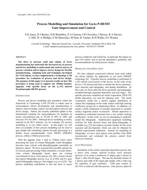
introduces a thin nitride layer prior to gate processing. Thegate stalk is defined by e-beam lithography in a single thinresist followed by nitride etch <strong>and</strong> gate recess etch in the<strong>GaAs</strong>/Al<strong>GaAs</strong> layers. The wide (0.5µm) gate cap is thenprocessed by (non self-aligned) optical lithography.<strong>Simulation</strong> is shown in figure 2 at gate deposition <strong>and</strong> afterlift-off. This process has potentially greater criticaldimension control of the gate stalk <strong>and</strong> throughput ascompared to A. <strong>Process</strong> control may also be improved by theearlier nitride passivation of the surface in this process.Possible concerns are additional gate variation introduced bythe nitride etch, increased parasitic capacitance (see later) <strong>and</strong>potential etch damage in the <strong>GaAs</strong>.A fully optical lithography process with linewidthreduction by spacers has been advocated by the authors of [4].<strong>Process</strong> modelling has investigated a possible process flow, C,to realise a 0.2µm gate. With careful control of humidity <strong>and</strong>resist thickness, a minimum line-width of 0.45µm can beroutinely defined with an i-line stepper. In a conventional<strong>HEMT</strong> process, topography from the nearby source/drainmetal lead to resist thickness non-uni<strong>for</strong>mity in the sourcedraingap <strong>and</strong> intolerable CD variation. These could bereduced by anti-reflection coatings, or by processing theohmic contacts after the gate (necessitating a refractory metalgate). Reduction of the original optically defined apertureline-width can be achieved through the creation of innerspacers by con<strong>for</strong>mal deposition <strong>and</strong> anisotropic etch of anitride film (figure 3) leading to a possible device structure(figure 4) consistent with the SEM result shown in [2].PROCESS SENSITIVITY ANALYSISWe have used the simulation tools to guide a cost-benefitanalysis of these three alternative gate processes. The purelyoptical lithography process C introduces additional sources ofvariation in the gate critical dimension (CD) control, due tothe inner spacer process (variations in the deposited spacermaterial thickness <strong>and</strong> etch add to the original gate aperturevariance). Estimates are shown in table 1 <strong>for</strong> differentassumptions in these three steps: a worst-case 10% variancein each of these steps, gives a total gate control 3σ of 24% at0.2µm. Better lithographic control is potentially achievablewith optical enhancement techniques such as PSM.For the mixed e-beam/optical gate process B, 2D devicesimulation [8] has been used to explore the effect ofmisalignment, giving rise to skew gates (schematically shownin figure 5), <strong>and</strong> the choice of gate stalk. In particular theparasitic contributions to C gs<strong>and</strong> C gd(see figure 6) from thefringing fields impact on the device gain. There is a trade-offbetween control of gate length <strong>and</strong> parasitic fringing fieldfrom the cap. At V ds=2V the additional contribution to gatecapacitance (C gs+C gd) variation from cap misalignment of0.15µm is 6% <strong>for</strong> a stalk height of 0.10 µm. This should becompared to the effect of gate CD variation in the tri-layerprocess A, <strong>for</strong> which the stalk height is ~0.16 µm. A 10%variation in L ggives an 8% variation in the total gatecapacitance. Thus to get per<strong>for</strong>mance equal to process A at2V, in process C we would need to control the gate length(combined e-beam lithography <strong>and</strong> nitride etch) variance tobetter than 8%, which implies that the e-beam process shouldaim to achieve 3σ=5%. In addition, the 0.1µm gate stalkgives rise to at least 6% higher mean gate capacitance thanprocess A, implying that the target gate length should bereduced to achieve the same per<strong>for</strong>mance. Note also that thegate cap misalignment has different effects at low <strong>and</strong> highdrain bias. At low bias, offsetting the gate cap to the drainside (“gamma gate” type structure) gives a reduction in C gs<strong>and</strong> increase in C gd. At high drain bias, C gsincreases due tothe lateral extension of the depletion region on the drain sideof the gate, which increases the effective channel length,giving rise to F Tdegradation. To some extent this can berectified by modifying the first recess geometry <strong>and</strong> <strong>GaAs</strong> capdoping, but at the expense of breakdown.CONCLUSIONSThis paper has demonstrated the use of 2D processmodelling in the study of three alternative gate processes.Although a purely optical lithography gate process, such as C,is attractive from throughput considerations, the gate controlis likely to be worsened due to several contributing processsteps, <strong>and</strong> the process is radically different from aconventional <strong>HEMT</strong>. From simulation, the combined e-beamstalk <strong>and</strong> optical gate cap process B looks promising <strong>for</strong>improving wafer throughput <strong>and</strong> gate length control.However, there is a trade-off between the control of the gatelength <strong>and</strong> additional parasitic fringing field variance from thecap. To achieve the same per<strong>for</strong>mance <strong>and</strong> process control asa pure e-beam trilayer resist process A having 10% gatevariation, would require a ~6% shorter gate length with 3σcontrol of better than 8%.REFERENCES[1] The International Technology Roadmap <strong>for</strong> Semiconductors,2000 Update, Modeling <strong>and</strong> <strong>Simulation</strong>, http://public.itrs.net/[2] H Brech, T Grave, S Selberherr, IEEE Trans Elec Dev 47(1)1957 (2000)[3] D R Brambley <strong>and</strong> R H Bennett, GEC Journal of Research,13(1) 42 (1996)[4] Takatomo Enoki et al Proc. <strong>GaAs</strong> IC-Symposium p337 (1994)[5] J. Muller et al. IEEE J. Solid State Circuits, 32(9), (1997)[6] Avant! Corporation Taurus-Topography v1998.4 <strong>and</strong>TSUPREM-4 v1999.4[7] Sigma-C SOLID <strong>and</strong> SELID software, http://www.sigma-c.de/[8] Silvaco ATLAS-BLAZE software
Figure 1 <strong>Simulation</strong> of <strong>Process</strong> A gate metal deposition (evaporation process) into a tri-layer resist mushroom gate structure shown after lift-off. (Results inthis <strong>and</strong> figures 2 -4 were obtained with Avant! Taurus-Topography <strong>and</strong> TSUPREM-4 software [6]).Figure 2 <strong>Simulation</strong> of <strong>Process</strong> B gate metal deposition (evaporation process) <strong>for</strong> an e-beam defined gate stalk window defined in a thin silicon nitride layer,with an optically defined gate cap, shown at gate deposition <strong>and</strong> after lift-off. The case of ideal alignment between cap <strong>and</strong> stalk is shown.Figure 3 <strong>Simulation</strong> of <strong>Process</strong> C optically defined gate using line-width reduction process. An aperture of ~0.45 micron is defined in the <strong>GaAs</strong> cap; siliconnitride is used to <strong>for</strong>m an inside spacer to reduce the aperture width.
Initial 0.45µm apertureprint feature control (3σ)Nitride Spacer totalcontrol (3σ)Final 0.2µm GateLength Control (3σ)± 0.045 µm (10%) ± 0.015 µm ± 0.047 µm (24%)± 0.035 µm (7.8%) ± 0.015 µm ± 0.038 µm (19%)± 0.035 µm (7.8%) ± 0.007 µm ± 0.035 µm (18%)± 0.023 µm (5%) ± 0.007 µm ± 0.024 µm (12%)Table 1 Estimated gate length control <strong>for</strong> the purely optical gate process Cbased on an initial i-line (365nm) aperture print of 0.45µm followed by anitride sidewall deposition <strong>and</strong> etch to reduce the gate length to a nominal0.20µm.Figure 4 Simulated structure <strong>for</strong> a possible purely optical gate process withself-aligned ohmics (c.f figure 1 in [2]).CapwhMisaligned Gate Cap offset towards DrainL gFigure 5 Schematic effects of misalignment of the gate cap <strong>and</strong> gate stalk <strong>for</strong> the mixed e-beam/optical lithography process B shown in Figure 2C (fF/mm)140012001000800600400200Cap w=0.5 h=0.1 symmetricLg=0.20Cap w=0.5 h=0.1 offset drainLg=0.20Cap w=0.5 h=0.1 offset sourceLg=0.20Cap w=0.5 h=0.16 symmetricLg=0.16-0.2400 1 2 3 4 5Vds (V)Figure 6 Modelled impact of misalignment in process B on the P<strong>HEMT</strong> Cgs <strong>and</strong> Cgd with a 0.5µm wide gate cap <strong>and</strong> a stalk height h=0.10µm <strong>for</strong>Lg=0.2µm as a function of Vds at Vgs=-0.3V. The effect of gate length variation 0.16-0.24 µm <strong>for</strong> a thicker stalk height of 0.16 µm with symmetric cap(process A) is also shown. (<strong>Simulation</strong> per<strong>for</strong>med with Silvaco ATLAS-BLAZE software [8]).