owneRs manual: Handling & SafeTy inSTrucTionS - Sig Sauer
owneRs manual: Handling & SafeTy inSTrucTionS - Sig Sauer
owneRs manual: Handling & SafeTy inSTrucTionS - Sig Sauer
You also want an ePaper? Increase the reach of your titles
YUMPU automatically turns print PDFs into web optimized ePapers that Google loves.
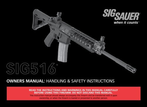
when it counts ®OWNERS MANUAL: <strong>Handling</strong> & Safety InstructionsRead the instructions and warnings in this <strong>manual</strong> carefullybefore using this firearm; do not discard this <strong>manual</strong>.This instruction <strong>manual</strong> should always accompany this firearm and be transferred with it uponownership, or when the firearm is loaned or presented to another person.
when it counts TEXAS:“IT IS UNLAWFUL TO STORE, TRANSPORT, OR ABANDON AN UNSECURED FIREARM IN A PLACE WHERE CHILDREN ARELIKELY TO BE AND CAN OBTAIN ACCESS TO THE FIREARM.”WISCONSIN:“IF YOU LEAVE A LOADED FIREARM WITHIN THE REACH OR EASY ACCESS OF A CHILD YOU MAY BE FINED OR IMPRISONEDOR BOTH IF THE CHILD IMPROPERLY DISCHARGES, POSSESSES, OR EXHIBITS THE FIREARM.”Please check with your licensed retailer, state police, or local police for additional warnings, which may be required bylocal law or regulation. Such regulations change constantly, and local authorities are in the best position to advise you onsuch legal matters.www.sigsauer.com 5
WARNING - LOCKING DEVICESThis firearm was originally sold with a key- operated locking device. While it can help provide secure storage for yourunloaded firearm, any locking device can fail. All guns are designed to fire if they are loaded and the trigger is pulled.Therefore, never install the locking device inside the trigger guard or in any way that makes it possible to pull the trigger!Do not leave the keys in the lock.The ultimate responsibility for secure storage of any firearm must depend upon its owner and his or her individualcircumstances. Firearms should be stored unloaded, in a secure location, separate from their ammunition.NEVER INSTALL THE LOCKING DEVICE INSIDE THE TRIGGER GUARDTo maximize effectiveness and reduce the chances of malfunction or damage to a firearm, ALWAYS refer to the lockingdevice’s manufacturer directions for installation and removal of the device.6 www.sigsauer.com
when it counts FIREARMS SAFETY IS YOUR RESPONSIBILITYThis owner’s <strong>manual</strong> is designed to assist you in learning how to use and care for your SIG SAUER ® pistol properly.Only when you are certain that you fully understand this <strong>manual</strong> and can properly carry out its instructions, should youpractice loading and firing your firearm with live ammunition. Having a gun in your possession is a full-time job; youcannot guess and you cannot forget. You must know how to use your firearm safely.If you have any doubts about your ability to handle or use this firearm safely, you should seek supervised instruction.The <strong>Sig</strong> <strong>Sauer</strong> Academy provides all levels of firearms safety and skill training, from beginner to expert.For more information contact:www.sigsaueracademy.com • (603) 679-2003Main campus:Satellite Facilities:Epping, New HampshireRange 82, Midland, VAnra Whittington Center, Raton, NMSAFETY MUST BE THE FIRST AND CONSTANT CONSIDERATION OFEVERY PERSON WHO HANDLES FIREARMS AND AMMUNITION.For more information about safety, responsible firearms ownership, and shooting sports, contact:National Rifle Association (NRA) of America, 11250 Waples Mill Road, Fairfax, VA 22030-74001-800-672-3888 • www.nra.comwww.sigsauer.com 7
TopicTABLE OF CONTENTSPageState by State Warnings 2-5Locking Device 6General Safety Information and Mechanical Characteristics 14Basic Rules of Safe Firearms <strong>Handling</strong> 151.0 Safety Information 141.1 Protect your Eyes and Ears 161.2 Ammunition 16-192.0 Mechanical Characteristics and Rifle Theory 212.1 Rifle Description 212.1.1 General 212.1.2 Barrel with Receiver and Gas System 212.1.3 Bolt and Bolt Carrier Assembly 222.1.4 Quad Rail Handguard 232.1.5 Lower Receiver and Buttstock Assembly 242.1.6 Gas Valve Position 26-298 www.sigsauer.com
when it counts TopicPage2.1.7 Buttstock Operation 302.1.8 Trigger Guard Operation 332.1.9 <strong>Sig</strong>hts 352.1.10 Magazine 382.2 Technical Specification 392.2.1 Operation of Fire Control Selector /Safety 40-413.0. <strong>Handling</strong> 423.1 Important Instructions 423.2 Loading the Magazine 433.3 Loading the Rifle 443.4 Reloading the Rifle (partially loaded magazine in rifle) 453.5 Reloading the Rifle (empty magazine in rifle) 464.0 Cycle of Operation 474.1 Firing 484.1.1 Unlocking of the Bolt, Extraction, and Ejection 484.1.2 Cocking of the Hammer 494.1.3 Chambering and Locking 495.0 Unloading 49www.sigsauer.com 9
TopicPage6.0 Procedures in case of a Stoppage 516.1 Failure to Fire (Cold Rifle) 516.2 Failure to Fire (Hot Rifle) 526.3 Failure to Cycle 536.4 Failure to Fire (Feedway Stoppage) 547.0 Field Strip Disassembly 557.1 Detailed Disassembly of the Bolt Carrier and Bolt 567.2 Extractor Removal 577.3 Gas Valve and Pushrod Removal 587.4 Quad Rail Removal 59-627.5 Removal of Recoil Buffer and Action Spring 62-638.0. Cleaning 648.1 Bore 658.2 Chamber 668.3 Bolt 668.4 Bolt Carrier 668.5 Action Spring and Receiver Extension 668.6 Magazine 679.0. Reassembly 689.1. Recoil Buffer and Action Spring 68-6910 www.sigsauer.com
when it counts TopicPage9.2 Extractor 709.3 Bolt to Bolt Carrier 71-739.4 Bolt Carrier to Upper Receiver 749.5 Rejoining Upper and lower Receivers 759.6 Quad rail Re-assembly 75-779.7 Pushrod and Gas Valve 78-7910.0 Perform a Function Check 8011.0 Lubrication 81-8212.0 Transportation and Storage 8313.0 Service and Replacement Parts Policy 8414.0 Shipping Firearms for Repair 86-8715.0 Parts List 88-8916.0 Parts Diagram 90-91SIG SAUER Limited Lifetime Firearms Warranty 92www.sigsauer.com 11
WARNINGS OF GREAT IMPORTANCEARE FOUND WITHIN THIS MANUALLocking Devices 6Alterations 13Manual Safety 25Ammunition 17, 20Lead Exposure 20<strong>Handling</strong> 42Loading 44Firing 47Storage 83Parts Purchasers 85Shipping 86OTHER CAUTIONS AND WARNINGS APPEAR THROUGHOUT THE MANUALFIREARMS ARE DANGEROUS WEAPONSREAD THE INSTRUCTIONS AND WARNINGS IN THIS MANUALTHOROUGHLY AND CAREFULLY BEFORE USING.12 www.sigsauer.com
when it counts WARNING - ALTERATIONSThis product was designed to function properly in its original condition.Alterations can make it unsafe. Do not alter any part or add or substitute anyparts or accessories not manufactured by SIG SAUER Inc.DO NOT ALTER ANY GUNwww.sigsauer.com 13
GENERAL SAFETY INFORMATION AND MECHANICAL CHARACTERISTICS1.0 Safety InformationThe safety warnings in this <strong>manual</strong> are important. By understanding the dangers inherent in the use of any firearm, andby taking the precautions described herein, you can enjoy complete safety in the use of your rifle. Failure to heed any ofthese warnings may result in serious injury to you or others, as well as severe damage to the firearm or other property.SIG SAUER Inc. shall not be responsible in any manner whatsoever for malfunctioning of the firearm, physical injury orproperty damage resulting inwhole or in part from:1) criminal or negligent discharge;2) improper or careless handling;3) unauthorized modifications;4) defective, improper, hand-loaded, or reloaded ammunition;5) corrosion;6) neglect; or7) other influences beyond our direct and immediate control.This limitation applies regardless of whether liability is asserted on the basis of contract, negligence, or strict liability(including any failure to warn). Under no circumstance shall SIG SAUER Inc. be liable for incidental or consequentialdamages, such as loss of use of property, commercial loss, and loss of earnings or profits.14 www.sigsauer.com
when it counts THE BASIC RULES OF SAFE FIREARMS HANDLING1. ALWAYS treat every gun as if it were loaded.2. ALWAYS be sure the barrel is clear of any obstruction.3. ALWAYS be sure of your backstop, what lies beyond, and the safety of bystanders before you shoot.4. ALWAYS use clean, dry, original factory-made ammunition of the proper type and caliber for your gun.5. ALWAYS wear ear protection and safety glasses when shooting.6. ALWAYS carry your gun so that you can control the direction of the muzzle if you fall or stumble.7. NEVER shoot at a flat surface or water.8. DO NOT leave an unattended gun loaded. Guns and ammunition should be stored separately, locked if possible, beyondthe reach of children, careless adults, and unauthorized users.9. NEVER allow your firearm to be used by anyone who has not read and understood this operator’s <strong>manual</strong>.10. DO NOT point any gun, loaded or unloaded, at any undesired target.11. NEVER fire your rifle near an animal unless it is trained to accept the noise: an animal’s startled reaction could injure itor cause an accident.12. NEVER drink alcoholic beverages or take drugs before or during shooting, as your vision and judgment could beseriously impaired, making your gun handling unsafe.www.sigsauer.com 15
1.1 Protect Your Eyes And EarsAlways wear safety glasses and ear plugs or “earmuff” type protectors whenever you are shooting. Always make certainthat persons close to you are similarly protected. Unprotected eyes may be injured by powder, gas, carbon residue,lubricant, metallic particles, or similar debris which may emanate occasionally from any firearm in normal use. Withoutear protection, repeated exposure to shootingnoise may lead to cumulative, permanent hearing loss.1.2. Ammunition1. Use only high quality, original, factory-manufactured ammunition. Do not use cartridges that are dirty, wet, corroded,bent, or damaged. Do not oil cartridges. Do not spray aerosol-type lubricants, preservative, or cleaners directly ontocartridges or where excess spray may flow into contact with cartridges. Lubricant or other foreign matter on cartridgescan cause potentially dangerous ammunition malfunctions. Use only ammunition of the caliber for which your firearm ischambered. The proper caliber is permanently engraved on your firearm; never attempt to use ammunition of any othercaliber.2. The use of reloaded, “remanufactured” hand-loaded, or other non-standard ammunition voids all warranties. Reloadingis a science and improperly loaded ammunition can be extremely dangerous. Severe damage to the firearm and seriousinjury to the shooter or to others may result. Always use ammunition that complies with the industry performancestandards established by the Sporting Arms and Ammunition Manufacturers’ Institute, Inc. of the United States (SAAMI) orammunition manufactured to military specifications.16 www.sigsauer.com
when it counts WARNING – AMMUNITION (CARTRIDGE) NOTICESIG SAUER Inc. SPECIFICALLY DISCLAIMS RESPONSIBILITY FOR ANY DAMAGE ORINJURY WHATSOEVER OCCURRING IN CONNECTION WITH, OR AS A RESULT OF, THE USE IN ANY SIG SAUER FIREARM OFFAULTY, NON-STANDARD, “REMANUFACTURED” HAND LOADED (RELOADED) AMMUNITION, OR CARTRIDGES OTHER THANTHOSE FOR WHICH THE FIREARM WAS ORIGINALLY CHAMBERED.3. Firearms may be severely damaged and serious injury to the shooter or to others may result from any conditioncausing excessive pressure inside the chamber or barrel during firing. Excessive pressure can be caused by obstructionsin the barrel, propellant powder overloads, the use of incorrect cartridges or defectively assembled cartridges. In addition,the use of a dirty, corroded, or damaged cartridge can lead to a burst cartridge case and consequent damage to thefirearm and personal injury from the sudden escape of high-pressure propellant gas within the firearm’s mechanism.4. Immediately stop shooting and check the barrel for a possible obstruction whenever:• You have difficulty in, or feel unusual resistance in, chambering a cartridge;• A cartridge misfires (does not go off);• The mechanism fails to extract a fired cartridge case;• Unburned grains of propellant powder are discovered spilled in the mechanism;• A shot sounds weak or abnormal. In such cases it is possible that a bullet is lodged part way down the barrel.• Firing a subsequent bullet into the obstructed barrel can wreck the firearm and cause serious injury to the shooteror to bystanders.www.sigsauer.com 17
when it counts 8. Do not oil cartridges, and be sure to wipe the chamber clean of any oil or preservative before commencing to shoot. Oilinterferes with the friction between cartridge case and chamber wall that is necessary for safe functioning, and subjectsthe firearm to stress similar to that imposed by excessive pressure.9. Use lubricants sparingly on the moving parts of your firearm. Avoid excessive spraying of any aerosol gun care product,especially where it may get on ammunition. All lubricants and aerosol spray lubricants in particular can penetratecartridge primers and cause misfires. Some highly penetrative lubricants can also migrate inside cartridge cases andcause deterioration of the propellant powder; on firing, the powder may not ignite. If only the primer ignites, there isdanger that the bullet may become lodged in the barrel.www.sigsauer.com 19
WARNING - AMMUNITIONDeath, serious injury, and damage can result from the use of wrong ammunition, boreobstructions, powder overloads, or incorrect cartridge components. Always wear shootingglasses and hearing protectors.IMPROPER AMMUNITION DESTROYS GUNSWARNING - LEAD EXPOSUREDischarging firearms in poorly ventilated areas, cleaning firearms, or handling ammunition mayresult in exposure to lead and other substances known to the state of California to cause birthdefects, reproductive harm, and other serious physical injury. Maintain adequate ventilation atall times. Wash hands thoroughly after exposure.SHOOTING OR CLEANING GUNS MAY EXPOSE YOU TO LEAD20 www.sigsauer.com
when it counts 2.0. Mechanical Characteristics and Rifle Theory2.1 Rifle Description2.1.1 GeneralThe SIG516 rifle is a gas operated short stroke pushrod rifle with a rotary bolt mechanism capable of semi-automaticoperation. Semi-Automatic is defined as one round being fired each time the trigger is pressed to the rear until themagazine is depleted of ammunition. The rifle is chambered in 5.56x45mm NATO and is compatible with .223 Remingtonammunition.2.1.2 Barrel, Receiver and Gas SystemThe barrel is mechanically mated to the receiver by means of a barrel nut, and the barrel extension. The flash suppressorif applicable is screwed onto the muzzle end of the barrel via ½ x 28 TPI thread pattern. The gas block, which is fitted tothe barrel, contains the gas port and the gas valve which locates the pushrod to the upper receiver. The upper receiverhas an integral M1913 accessory rail for attachment of sights or optics.FIG 1 Barrel with receiver and gas systemwww.sigsauer.com 21
2.1.3. Bolt/Bolt Carrier AssemblyThe bolt carrier guides the bolt and controls locking and unlocking by means of the cam pin. The bolt carrier alsoincorporates an integral contact surface for the pushrod. The bolt carrier is responsible for cocking the hammer.Cam PinBolt CarrierFIG 2 Bolt CarrierBoltThe bolt houses the firing pin, the extractor and the ejector. It incorporates locking lugs that lock the bolt into the barrelextension. The cam pin passes into the bolt which allows for locking and unlocking and is retained in the bolt by the firing pin.Bolt RingsEjectorFIG 3 Bolt AssemblyExtractor22 www.sigsauer.com
when it counts 2.1.4. Quad Rail Hand GuardThe quad rail hand guard protects the barrel and the gas system from damage and provides protection from barrel heat.The integrated M1913 accessory rails provide attachment points for various devices , such as lights, lasers, sights, andbi-pods. The quad rail hand guard has unique attachment features that enhances the rifle overall structural integrity.FIG 4 Quad Rail assembly on riflewww.sigsauer.com 23
2.1.5. Lower Receiver Assembly and Butt stockThe lower receiver assembly contains the fire control mechanism, bolt catch, magazine well, magazine release, pistolgrip, sling attachment points, and butt stock assembly. The fire control selector is ambidextrous along with the magazinecatch. The fire control selector has two positions, SAFE-SEMI.SAFE - Trigger is locked and rifle cannot be fired.SEMI - The rifle will fire one shot with each press of the trigger.Bolt Catch LeverSling attachment pointMagazine releaseFire control selectorFIG 5 Lower receiver assembly24 www.sigsauer.com
when it counts MANUAL SAFETY “ON”MANUAL SAFETY “OFF”FIG 6 Fire Control Selector position Safe-semiWARNING - MANUAL SAFETY:Keep the safety “ON” unless actually firing. Always move the safety to its intended position and check it. The safety isnot “ON” unless it is completely “ON.” Never depend on a safety mechanism or any other mechanical device to justifycareless handling or permitting the rifle to point in an unsafe direction. The only “safe” rifle is one in which the bolt isopen, the chamber is empty, and there is no magazine in the gun.KNOW HOW TO USE THE SAFETYwww.sigsauer.com 25
The SIG516 is equipped with a telescoping butt stock. The butt stock may vary depending on the model.FIG 7 Magpul MOE Butt StockRelease Latch2.1.6 Gas Valve PositionThe SIG516 gas valve has 3 or 4 positions depending on the model configuration.Gas ValveFIG 8 Adjustable Gas ValveGas Block26 www.sigsauer.com
when it counts 2.1.6.A. Position #1(Normal) is for normal operation.FIG 9 Gas Valve ON P12.1.6.B. Position #2(Adverse) is for adverse conditions such as fouling or short stroking.FIG 10 Gas Valve ON P2 AdverseCAUTION: The rifle should NOT be operated in Position #2 (Adverse) for an extended period of time. As soon as normalfunction returns, the gas valve should be rotated to Position #1 (Normal). Continued operation with the gas valve inPosition #2 (Adverse) will increase recoil and place unnecessary stress on the rifle. Having to operate the rifle in Position#2 (Adverse) is an indicator that the rifle needs maintenance.www.sigsauer.com 27
2.1.6.C. Position #3(Suppressed) is for firing with a sound suppressor and is a partial cutoff of the gas system still allowing for cycling of theweapon. You must depress the valve plunger prior to rotating the gas valve to this position.FIG 11 Gas Valve ON Suppressed Mode (action will cycle)2.1.6.D. Position #4 (OPTIONAL)(Off) is a complete cutoff of the gas system allowing the rifle to function as a single shot weapon.FIG 12 Gas Valve ON P4 Position, Suppressed Mode (the action will not cycle)28 www.sigsauer.com
when it counts When the cycle of operation is affected by fouling or environmental conditions, the gas valve can be rotated to thePosition 2 detent. In this position, a larger volume of gas is released against the pushrod. The need to utilize this positionis an indication that the rifle requires cleaning.www.sigsauer.com 29
2.1.7. Butt Stock OperationThe butt stock on the SIG516 may vary depending on the specific model you have. The butt stock provides for easyadjustment of the length to accommodate the individual shooter or for storage. To adjust the length of the butt stock,fully depress the release latch and pull the stock rearward to extend or push the stock forward to collapse.Intermediate positions may be selected by partially depressing the release latch and moving the stock to the desiredposition.FIG 13 Butt Stock collapsed and fully extendedRelease Latch30 www.sigsauer.com
when it counts To remove the butt stock:Depress the adjustment lever to disengage the release latch and slide the stock to full extension.Grasp both ends of the release pin and pull down as you slide the stock from the receiver extension.FIG 14 Butt Stock removalwww.sigsauer.com 31
To re-install the butt stock:DO NOT FORCE THE PARTS TOGETHER! Align the stock body with the receiver extension and Gently slide the butt stockonto the receiver extension until it stops (About 2 1/8”) Grasp the release pin on both ends and pull down as you slide thestock the rest of the way on to the receiver extension.Check to see that the stock moves to all positions locks into place.FIG 15 Insert view of Butt Stock installation32 www.sigsauer.com
when it counts 2.1.8. Trigger Guard OperationThe trigger guard may be released from its normal position to make the trigger accessible for shooting with gloves. Forsafety reasons the trigger guard must not be released until just before firing the weapon. It should be returned to itsnormal position immediately.CAUTION: BE CAREFUL WHEN INSERTING GLOVED FINGERS INTO THE TRIGGER GUARD AS ACCIDENTAL DISCHARGES MAYOCCUR!To release the trigger guard, depress the spring loaded detent on the front right side and rotate the guard downward.FIG 16 Trigger and guard releaseTo close the guard rotate the trigger guard back into place, depress the spring loaded detent and ensure the guard locksinto place.www.sigsauer.com 33
WARNING:DO NOT MANIPULATE THE TRIGGER GUARD UNLESS THE FIRE CONTROL SELECTORIS ON “SAFE” AND THE RIFLE IS UNLOADED.34 www.sigsauer.com
when it counts 2.1.9. <strong>Sig</strong>htsThe SIG516 rifle features integrated Mil-Std M1913 rails on the upper receiver and the Quad Rail Hand Guards. Theserails may be used for attaching a variety of sighting systems, both optical and fixed. Some models feature SIG SAUER flipup front and rear sights as a standard feature. These sights are designed to provide a simple, durable sighting solutionshould you decide not to use an optical device. Markings on all rail surfaces give you a reference point to reattach yoursighting system in exactly the same place should you need to remove it for service.FIG 17 Front and rear sightswww.sigsauer.com 35
<strong>Sig</strong>ht DeploymentFlip up the front sight assembly until it held in the upright position by the detent.Flip up the rear sight assembly until it is held in the upright position by the detent.When the sights are not longer required, rotate them down to their stowed position.Windage Adjustment (Left/Right)Windage ScrewFIG 18 REAR SIGHT WINDAGE ADJUSTMENTElevation AdjustmentWindage ScrewFIG 19 FRONT SIGHT POST DETAILING DETENT FOR ADJUSTMENT36 www.sigsauer.com
when it counts CHANGES IN POINT OF IMPACT ON A 25M TARGET (16.0” BARREL)ELEVATIONWINDAGE1 CLICK 1.2cm 1 CLICK 0.5cm2 CLICKS 2.3cm 2 CLICKS 0.9cm3 CLICKS 3.5cm 3 CLICKS 1.4cm4 CLICKS 4.7cm 4 CLICKS 1.9cmTo move your shot group UP rotate the front sight post clockwiseTo move your shot group DOWN rotate the front sight post counter clockwiseTo move your shot group to the LEFT rotate the windage screw counter clockwiseTo move your shot group to the RIGHT rotate the windage screw clockwisewww.sigsauer.com 37
2.1.10. MagazineThe SIG516 rifle ships with (1) one thirty (30) round aluminum magazine. The SIG516 is compatible with most M16/AR15type magazines.Aftermarket magazines should always be checked for proper fit and function prior to using them with the SIG516 rifle.FIG 20, 20 AND 30 RD MAGAZINE38 www.sigsauer.com
when it counts 2.2. Technical SpecificationsSPECIFICATION PATROL PRECISION MARKSMANCALIBER 5.56x45mm NATO 5.56x45mm NATOLENGTH W/ STOCK COLLAPSED 36.0” N/ALENGTH W/ STOCK EXTENDED 39.5” 36.2”-37.3”BARREL LENGTH 16.0” 18.0”NUMBER OF GROOVES 6 6RATE OF TWIST 1:07 1:07WEIGHT W/O MAGAZINE 7.3 LBS 8.05 LBSMAGAZINE (SHIPPED WITH) 30 RD 20 RDSTOCK MagPul MOE MagPul PRSTRIGGER Standard Single Stage 2 Stage Matchwww.sigsauer.com 39
2.2.1 Operation of Fire Control/SafetyFour basic fundamentals of safe firearm handling should be applied during any and all activities described in this <strong>manual</strong>.Treat every firearm as if it were loaded.Always keep the muzzle pointed in a safe direction until ready to shoot.Keep your finger off of the trigger and out of the trigger guard until ready to fire.Be aware of your target and what is beyond it.The SIG516 is equipped with an ambidextrous fire control selector lever commonly referred to as a “safety lever” which canbe manipulated from either the left or right side of the lower receiver. The selector has two (2) positions, SAFE and SEMI.SAFE - Trigger is locked and rifle CANNOT be fired with a normal press of the trigger.Manual Safety “ON”Fig 21 FIRE CONTROL SELECTOR ON SAFE40 www.sigsauer.com
when it counts SEMI – The trigger is no longer locked and the rifle WILL FIRE one shot with each press of the trigger until either theoperator stops firing or the ammunition is expended from the magazine.MANUAL SAFETY “OFF”Fig 22 FIRE CONTROL SELECTOR ON SEMIThe fire control selector should always be in the SAFE position except when the operator is actually going to fire the rifle,and upon completion of firing.www.sigsauer.com 41
3.0 <strong>Handling</strong>3.1 Important Instructions• Before manipulating the weapon, ensure the fire control lever is in the “S” (SAFE) position and the trigger guard is inthe closed position.• Use only factory-new ammunition which corresponds to the caliber of the weapon.• During all manipulations of the rifle, point the weapon in a safe direction.• Do not place your finger on the trigger until the target has been verified and you intend to shoot.• Do not load the weapon until immediately before use.• Unload weapon immediately after shooting is finished.• Remove the bolt carrier assembly and magazine from the weapon prior to transportation.•WARNING - HANDLING:Never carry the rifle loaded with the safety lever in the “F” (FIRE) position. If dropped or struck with the safety off (“F”),the rifle may fire. Such a discharge can occur with or without the trigger being directly struck or touched. Never rest aloaded rifle against any object (wall, tree, fence, vehicle, etc.) because there is always the possibility that the rifle willbe jarred or slide from its position and fall with sufficient force to discharge. Keep the safety lever on “S” (SAFE) unlessactually firing.ANY GUN MAY FIRE IF DROPPED42 www.sigsauer.com
when it counts 3.2 Loading the MagazineFIG 23 516 MAGAZINE BEING LOADED1. Ensure the magazine is the proper type and caliber for the rifle;2. Place a round between the feed lips and press down- ensure the bullet is facing the front of the magazine;3. Ensure the cartridges are fully seated to the rear of the magazine by tapping the back of the magazine in the palm ofthe hand.www.sigsauer.com 43
when it counts 3.4 Reloading the Rifle after firing has commenced (partially loadedmagazine still in rifle).1. Place fire control selector on SAFE.2. Keep muzzle pointed in a safe direction and finger out of the trigger guard!3. Depress magazine catch and remove magazine.FIG 25 MAG CATCH BEING DEPRESSED LEFT AND RIGHT SIDE4. Insert loaded magazine and ensure it is seated properly.www.sigsauer.com 45
3.5 Reloading the Rifle after firing has commenced (bolt locked open, emptymagazine still in rifle).1. Place fire control selector on SAFE.2. Keep muzzle pointed in a safe direction and finger out of the trigger guard!3. Depress magazine catch and remove magazine.4. Insert loaded magazine and ensure it is seated properly.5. Release the bolt by either:a. Depressing bolt catch fully releasing the bolt;b. Grasping the charging handle, retracting it slightly and releasing it.WHEN COMPLETING STEP 5.B ABOVE, RELEASE THE CHARGING HANDLE AND LET IT GO FORWARD UNDER FULL SPRINGPOWER. DO NOT RIDE THE CHARGING HANDLE FORWARD AS THIS MIGHT CAUSE A FAILURE OF THE CARTRIDGE TO FULLYSEAT INTO BATTERY.46 www.sigsauer.com
when it counts 4.0 Cycle of OperationReady to Fire ConditionThe SIG516 “Ready to Fire” condition is described as a loaded magazine properly seated into the magazine well, a livecartridge loaded into the chamber, the fire control selector place on “SAFE”.WARNING - FIRINGThe bolt automatically opens and shuts quickly while firing. Keep face andhands away from it. Hot brass and powder gas is ejected quickly and canburn you. The rifle should be fired from the right shoulder. Always wearshooting glasses and hearing protectors.BOLT OPENS FAST – HOT BRASS EJECTEDwww.sigsauer.com 47
4.1. FiringRotate the fire control selector from the “SAFE” position to the “SEMI” position.Pressing the trigger rearward releases the hammer causing it to strike the firing pin, impacting the cartridge primer.CAUTION: THE SIG516 IS A SEMI-AUTOMATIC RIFLE AND WILL AUTOMATICALLY RELOAD THE NEXT CARTRIDGE IN THEMAGAZINE AFTER THE CHAMBERED CARTRIDGE IS FIRED FOLLOWING ONE PRESS OF THE TRIGGER. THE RIFLE WILL NOWBE READY TO FIRE AGAIN ONCE THE TRIGGER IS RELEASED.4.1.1. Unlocking of Bolt; Extraction & Ejection1. The gas pressure generated by the burning powder in the cartridge, propels the bullet through the bore of the barrel.2. When the bullet passes the gas port in the barrel a portion of the gas flows up into the gas block and into the gas valve.3. The gas travels through the port in the adjustable gas valve and drives the pushrod rearward.4. The pushrod then pushes the bolt carrier assembly to the rear.5. As the bolt carrier moves rearward the cam pin allows the bolt to rotate to the right and unlock from the barrelextension.6. As the bolt carrier continues rearward movement the extractor, gripping the right side of the expended cartridge casepulls the case from the chamber.7. Once the expended case clears the chamber, the ejector located on the left side of the bolt face pushes the case outthe ejection port located on the right side of the upper receiver.48 www.sigsauer.com
when it counts 4.1.2. Cocking of the Hammer1. As the bolt carrier assembly continues rearward the bottom surface of the bolt carrier cocks the hammer rearward.2. The hammer is then captured by the disconnect and held in place.4.1.3 Chambering and Locking1. Once the bolt carrier reaches its full rearward travel the buffer and recoil spring force the bolt carrier assembly forward.2. As the bolt carrier assembly moves forward the next cartridge is stripped from the magazine and loaded into the chamber.3. The bolt continues forward, rotates to the left, and locks into place.4. The trigger is released and the hammer moves to its location of engagement with the trigger.5. The rifle is now ready to be fired again.5.0. UnloadingALWAYS MAKE SURE THE MUZZLE IS POINTED IN A SAFE DIRECTION!1. Ensure the fire control selector is rotated to the “SAFE” position.2. Remove the magazine by depressing the magazine catch; and3. Retract the charging handle locking the bolt carrier assembly to the rear; and4. Visually and physically inspect the chamber to verify it is empty.Remember to clear the chamber after the magazine is removed.Never assume that any firearm is unloaded until you have personally checked it, visually and physically.After every range session make sure the firearm is unloaded before you leave the range.www.sigsauer.com 49
WARNING:Removing cartridges from the magazine does not prevent the rifle from being fired! When there is a cartridge in thechamber and the safety lever is in the “F” (FIRE) position, the cartridge will discharge if the trigger is pulled. It is absolutelyessential for the user to know how to completely unload the rifle.“Completely” means emptying the magazine and removing a chambered cartridge. The safety lever should always be inthe “S” (SAFE) position when the rifle is being unloaded.THE RIFLE WILL FIRE EVEN IF THE MAGAZINE IS EMPTY OR REMOVED50 www.sigsauer.com
when it counts TO CLEAR A STOPPAGE (JAM)6.0. Procedures In Case of a StoppageA “Stoppage” is an interruption in the cycle of operation as depicted in Section 4.0. A stoppage can normally be repairedby the operator by performing one of the following immediate actions described.6.1. Failure to Fire (Cold Rifle) Trigger is pressed, hammer falls, rifle does not fire.1. Ensure the magazine is properly seated in the magazine well by applying upward pressure and then pulling down onthe magazine.2. Retract the charging handle all the way back and observe the ejection of the expended case or a live cartridge; and3. Visually inspect the chamber for any obstructions, if the chamber shows to be clear, release the charging handle tofeed a new cartridge. Do NOT ride the charging handle forward.4. Attempt to fire the rifle again.www.sigsauer.com 51
6.2. Failure to Fire (Hot Rifle) Trigger is pressed, hammer falls, the rifle doesnot fire.1. Keep the muzzle pointed down range, place the rifle on SAFE, remove the magazine, if you cannot extract the loadedcartridge within ten (10) seconds you must wait a minimum of 15 minutes before handling the rifle.2. Upon completion of the 15 minutes, retract the charging handle all the way back and observe the ejection of thecartridge; and3. Visually inspect the chamber for any obstructions, if the chamber shows to be clear, release the charging handle tofeed a new cartridge. DO NOT ride the charging handle forward.4. Attempt to fire the rifle again.If the rifle does not fire after completing 6.1 or 6.2:1. Unload, and clear the rifle. 3. Cycle the bolt assembly chambering a round; and2. Insert a fresh magazine; 4. Attempt to fire the rifle.If the rifle fails to fire after attempting all of the above, the rifle should be returned to SIG SAUER, Inc. for evaluation by afactory trained technician.WARNING:EXCESSIVE HEAT BUILD UP IN THE CHAMBER CAN CAUSE WHAT IS REFERRED TO AS A “COOK OFF”. THIS MEANS THEHEAT IN THE CHAMBER CAUSES THE POWDER TO IGNITE IN THE CHAMBERED CARTRIDGE. THE ROUND THEN DETONATESJUST AS IF IT WERE FIRED. IF THE RIFLE HAS BEEN FIRED FOR AN EXTENDED PERIOD OF TIME FOLLOW THE STEPS IN 6.2.52 www.sigsauer.com
when it counts 6.3. Failure to CycleWARNING:Always ensure the rifle is unloaded and cleared of ammunition prior to adjusting the gas valve as described below.If the SIG516 fires one round but fails to cycle the action:1. Place the fire control selector to “SAFE”2. Remove the magazine; and3. Lock the bolt carrier to the rear;4. Ensure the chamber is clear (visual and physical check);5. Rotate the gas valve from Position #1 (Normal) toPosition # 2 (Adverse);6. Reinsert a fresh magazine;7. Release the bolt forward; and8. Rotate the fire control selector to “SEMI” and attemptto fire the rifle.FIG 26 gas valve rotated to position 2www.sigsauer.com 53
6.4. Feedway Stoppage (Jam)A feedway stoppage occurs when one or more rounds are trapped in the upper receiver and stop the cycle of operation.To clear this problem:1. Place the rifle on SAFE.2. Remove the magazine (You might have to pull downward with some force to remove the magazine from the magazinewell due to the jammed cartridges).3. Cycle the bolt carrier assembly several times to clear any rounds from the receiver; and4. Lock the bolt carrier to the rear, conduct a visual and physical inspection of the chamber to make sure the chamberhas no obstructions; and5. Insert a fresh magazine and continue to fire the rifle.CAUTION: Always remove the source of ammunition (magazine) prior to attempting to clear a stoppage that requiresretracting the charging handle/bolt carrier assembly as unintentional release of the spring loaded bolt carrier assemblycould detonate live cartridges lodged in the upper receiver.54 www.sigsauer.com
when it counts 7.0. Field Strip Disassembly1. Unload and clear the rifle per section 5.0.2. Ensure the bolt carrier assembly is forward and the fire control selector is placed on SAFE.3. Press the takedown pin from left to right until it stops (It is held into the lower receiver by a detent and will not pull freefrom the receiver).Takedown PinPivot PinFIG 27 THE TAKEDOWN PIN AND PIVOT PINwww.sigsauer.com 55
1. Press the Pivot Pin (front pin) from left to right until it stops at the detent.2. Separate the upper receiver from the lower receiver.3. Grasp the charging handle and pull it rearward until it stops.4. Remove the bolt carrier assembly from the rear opening of the upper receiver.5. Align the tabs of the charging handle and lift it from the receiver.7.1. Detailed Disassembly of the Bolt Carrier and Bolt.1. Remove the firing pin retaining pin from the left side of the bolt carrier. A small punch might be needed for thisprocedure.2. Tilt the bolt carrier upward and catch the firing pin as it slides out of the rear of the bolt.3. Rotate the bolt cam pin ¼ turn and lift it straight up out of the bolt carrier.4. Pull the bolt out from the front of the bolt carrier.FIG 28 INSERT DETAILED DIAGRAM OF BOLT AND BOLT CARRIER56 www.sigsauer.com
when it counts 7.2. Extractor Removal1. Apply slight pressure to the rear of the extractor with the thumb.2. Using a punch, or the tip of the firing pin, push out the extractor pin. from either side.3. Remove the extractor from the bolt.Retaining PinExtractorFIG 29 BOLT WITH EXTRACTOR REMOVEDNOTE: Only separate the extractor spring from the extractor when replacement is necessarywww.sigsauer.com 57
7.3. Gas Valve and Pushrod Removal1. Depress the gas valve plunger on the gas block and begin rotating the gas valve counterclockwise.2. Continue to unscrew the gas valve from the gas block until the threads are clear of the gas block.3. Pull the gas valve free of the gas block.Tilt the barrel downward and allow the pushrod assembly to slide out of the gas block.FIG 30 PICTURE OF THE GAS VALVE BEING REMOVED58 www.sigsauer.com
when it counts 7.4. Quad Rail RemovalCAUTION: DO NOT REMOVE THE QUAD RAIL ASSEMBLY UNLESS THE UPPER AND LOWER RECEIVERS ARE SEPARATED.REMOVAL OF THE QUAD RAILS WILL EXPOSE THE PUSHROD ASSEMBLY. SHOULD THE RIFLE FALL OR STRIKE A HARDSURFACE, THE PUSHROD ASSEMBLY COULD BE DAMAGED EFFECTING OPERATION OF THE RIFLE. SEPARATING THERECEIVERS REDUCES THE OVERALL WEIGHT OF THE RIFLE REDUCING THE RISK OF DAMAGE SHOULD THE RIFLE FALL ORSTRIKE A HARD OBJECT OR SURFACE.FIG 31 EXPLODED VIEW OF QUAD RAILwww.sigsauer.com 59
1. Remove the two (2) quad clamp screws using a 1/8” hex wrench.FIG 32 REMOVAL OF CLAMP SCREWS AND CLAMP2. Remove the four (4) handguard screws from the lower quad rail using a 5/32” hex wrench; andFIG 33 REMOVAL OF 4 HANDGUARD SCREWS60 www.sigsauer.com
when it counts 3. Remove the lower quad rail section.FIG 34 REMOVAL OF THE LOWER RAIL SECTION4. Lift the quad key from the slot in the barrel nut.FIG 35 REMOVAL OF THE QUAD KEY FROM BARREL NUTwww.sigsauer.com 61
5. Remove the upper rail section.FIG 36 REMOVAL OF UPPER RAIL SECTION7.5. Removal of Recoil Buffer and Action SpringREMOVAL OF THE RECOIL BUFFER AND SPRING IS EASIER IF THE HAMMER IS IN THE COCKED POSITION AND THE FIRECONTROL SELECTOR IS ROTATED TO THE SAFE POSITION. ALWAYS WEAR SAFETY GLASSES WHEN HANDLING PARTSUNDER SPRING TENSION.62 www.sigsauer.com
when it counts 1. Depress buffer retaining plunger while maintaining control the buffer as you allow it to move forward from the receiverextension tube.FIG 37 PICTURE OF THUMB OVER BUFFER ASSEMBLY2. Guide the buffer and action spring from the receiver extension.3. Use a clockwise twisting motion to separate the action spring from the recoil buffer.Do NOT pull straight back on the action spring as it can cause damage to the spring.FIG 38 BUFFER AND RECOIL SPRING REMOVALwww.sigsauer.com 63
8.0. Cleaning1. Your rifle is delivered factory packaged and preserved with a light coating of protective grease and oils. Beforeloading make certain that all packing grease and oil has been cleaned from the bore and exposed mechanism.2. Before you begin to disassemble your firearm for cleaning, always double-check to make sure it is unloaded!3. After cleaning always check to be sure that no cleaning patch or other obstruction remains in the bore or chamber!ONLY USE CLEANING AND LUBRICATION PRODUCTS THAT ARE SPECIFICALLY DESIGNED FOR USE ON FIREARMS.DO NOT USE WIRE BRUSHES ON ALUMINUM SURFACES SUCH AS THE RECEIVERS OR QUAD RAILS AS THIS MAY SCRATCHTHE FINISH.READ ALL WARNING LABELS AND OBTAIN MSDS ON ANY CLEANING, LUBRICATION, AND PROTECTIVE CHEMICALS USED.CLEANER, LUBRICANT, PROTECTANT IS COMMONLY REFERRED TO AS “CLP”SOME BORE CLEANERS ARE NOT MEANT TO BE LEFT IN THE BORE FOR EXTENDED PERIOD OF TIME.FOLLOW ALL MANUFACTURER’S INSTRUCTIONS AND CAUTIONS WHEN USING CLEANING OR LUBRICATION PRODUCTS ONFIREARMS.SOLVENT IS A GENERIC TERM AND WILL BE USED TO DESCRIBE A GENERAL BORE CLEANING SOLUTION.64 www.sigsauer.com
when it counts 8.1. Cleaning the Bore1. Run a patch soaked in solvent through the bore.2. Allow the solvent to soak in the barrel for at least 5 minutes.3. Move on to section 8.3 and clean the bolt while the solvent works on loosening the residue in the bore of the barrel.4. If the barrel is heavily fouled use a cleaning rod and a brass or nylon bore brush of the proper bore diameter and cleanthe bore from the chamber end to the muzzle end. Pass the brush completely out past the muzzle and do not changedirection in the bore as the brush can become stuck in the bore.5. Run cotton patches through the bore until the patches come out clean. The bore and chamber of the barrel may belightly lubricated with an oily patch if the rifle is to be stored. Upon returning the rifle to service you must remove the oilby running a dry patch through the barrel.8.2. Cleaning ChamberKeep muzzle pointed upward to keep chamber residue from running down into the cleaned bore.1. Use a chamber brush coated in solvent to clean chamber.2. Use a minimum of five (5) plunge strokes and three (3) 360 degree clockwise rotations.3. Clean residue with cotton patches, swabs or a chamber mop.www.sigsauer.com 65
8.3. Cleaning the BoltA cotton patch or a soft toothbrush and solvent can be used to complete the following steps:1. Clean all fouling from around the bolt locking lugs.2. Clean all fouling from bolt body3. Clean extractor and the extractor slot in the bolt.4. Use pipe cleaner to clean firing pin channel.8.4. Cleaning the Bolt Carrier1. Clean all fouling from bolt carrier body.2. Clean the bolt channel in the front of the carrier with a brush or cotton swabs.8.5. Action Spring and Receiver Extension1. Clean with rag and solvent.2. Wipe dry.66 www.sigsauer.com
when it counts 8.6. Cleaning the MagazineMagazines should be cleaned whenever the rifle is cleaned as preventive maintenance.FIG 39 MAGAZINE1. Use a brush to clean inside the body.2. Clean with a rag and CLP then wipe dry.3. Clean follower and dry completely.The magazine body should be kept dry. Any oil or solvent left behind will attract dirt and debris causing undue wear andpossibly feeding issues.www.sigsauer.com 67
9.0 Reassembly9.1. Recoil Buffer and Action Spring1. Slide the action spring over the recoil buffer and snap it into place by using a clockwise twisting motion as you press itforward.FIG 40 SPRING TO BUFFER68 www.sigsauer.com
when it counts 2. Insert the action spring into the receiver extension tube.FIG 41 ACTION SPRING AND BUFFERSTARTED INTO RECEIVER EXTENSION3. Push the recoil buffer back into the receiver extension until the buffer retaining plunger engages the face of the bufferand holds it into the receiver extension.FIG 42 BUFFER HELD INTO RECEIVER EXTENSIONwww.sigsauer.com 69
9.2. Extractor1. Fit extractor to bolt body by holding bolt in one hand; and2. While applying pressure with thumb over the spring end of the extractor, slide extractor pin into hole until ends areflush with bolt body.FIG 43 EXTRACTOR TO BOLT BODY70 www.sigsauer.com
when it counts 9.3. Bolt to Bolt CarrierWARNING:THE BOLT CAM PIN MUST BE INSTALLED OR THE RIFLE WILL SUFFER A CATASTROPHIC FAILURE WHICH COULD RESULT INSERIOUS INJURY OR DEATH TO THE OPERATOR.DO NOT INTERCHANGE BOLT ASSEMBLIES FROM ONE RIFLE TO ANOTHER. DOING SO COULD RESULT IN SERIOUS INJURYOR DEATH TO THE OPERATOR.www.sigsauer.com 71
1. Re-insert the bolt into the bolt carrier with the extractor oriented to the right side of the bolt carrier; andFIG 44 ALIGN BOLT INTO CARRIER BODYAlignment of Bold and Carrier2. Pull the bolt forward to the unlocked position; and align the cam pin hole inserting the cam pin into the bolt; and3. Insert the firing pin into the tail shaft of the bolt.Camp Pin installedFIG 45 CAM PIN BACK INTO BOLT AND CARRIER72 www.sigsauer.com
when it counts CAUTION: THE FIRING PIN MUST BE FULLY INSERTED INTO THE BOLT CARRIER PRIOR TO INSTALLATION OF THE FIRING PINRETAINING PIN. THE RETAINING PIN MUST PASS BETWEEN THE LARGE SHOULDER OF THE FIRING PIN AND THE HEAD OFTHE FIRING PIN.FIG 46 FIRING PIN INSERTED INTO BOLT/CARRIER4. Re-install the firing pin retaining pin into the bolt carrier from left to right.5. Point the bolt carrier assembly with the bolt face upward and ensure the firing pin is properly retained in the carrier bylightly slapping the bolt face back into the carrier (locked position). The firing pin should NOT fall out of the carrier.www.sigsauer.com 73
9.4. Bolt Carrier Assembly to Upper Receiver1. Position the upper receiver assembly with the open bottom facing upward; and2. Insert the charging handle into the slotted key way of the receiver and push it forward slightly.3. Take the bolt carrier assembly with the bolt pulled completely forward (unlocked position) and set it into the charginghandle.4. Simultaneously push the bolt carrier assembly and the charging handle forward until the bolt and the charging handlelock into place.FIG 47 REINSTALLATION OF THE BOLT CARRIER ASSEMBLY TO UPPER RECEIVER74 www.sigsauer.com
when it counts 9.5. Rejoining Upper and Lower ReceiversTo aid in steps 1-3, <strong>manual</strong>ly cock the hammer by pushing it down until it is held in place then rotate the fire controlselector to SAFE.1. Position the upper and lower receivers to align the pivot pin (front pin) holes.2. Push the pivot pin from right to left until the head of the pivot pin is flush against the receiver. You will feel it capturedby the detent pin.3. Close the receivers together and push the takedown pin (rear pin) from right to left until the head of the takedown pinis flush against the receiver. You will feel it captured by the detent pin as you did the pivot pin.9.6. Quad Rail Reassembly1. Pre-assemble the rail clamp and quad key to the lower rail section leaving the two (2) clamp screws loose.FIG 48 QUAD KEY AND RAIL CLAMP PRE-ASSEMBLEDwww.sigsauer.com 75
2. Place the upper rail section over the barrel nut interlocking the tab into the upper receiver pocket.FIG 49 RE-INSTALLATION OF UPPER RAIL SECTION WITH INTERLOCKING TAB HIGHLIGHTED3. Place the lower rail section over the barrel nut ensuring that the key is seated into the groove of the barrel nut.FIG 50 RE-INSTALLATION OF LOWER RAIL SECTION76 www.sigsauer.com
when it counts 4. Install the four (4) rail screws using a 5/32” hex wrench. Tighten the screws to 60 inch pounds (7 Newton meters).FIG 51 TIGHTENING OF RAIL SECTION SCREWS5. Tighten the clamp screws to 70 inch pounds (8 Newton meters) using a 1/8” torque wrench.6. Repeat step 5 one time.FIG 52 TIGHTENING OF RAIL CLAMP SCREWSwww.sigsauer.com 77
9.7. Pushrod and Gas Valve re-assemblyTo simplify the process of reinstalling the pushrod assembly, always pre-assemble the gas valve into the pushrod prior toattempting reinsertion of the pushrod through the gas block. This will help in guiding the pushrod into the upper receiver.FIG 53 PUSH ROD AND GAS VALVE1. Install the pushrod assembly through the front of the gas block with the flat side of the spring guide facing downwardtoward the barrel nut.FIG 54 ALIGNMENT OF SPRING RETAINER TO BARREL NUT78 www.sigsauer.com
when it counts 2. Begin to thread the gas valve into the gas block clockwise; andFIG 55 GAS VALVE ROTATIonFIG 56 FINAL GAS VALVE POSITIONDepress the valve plunger and continue to screw the gas valve into the gas block until the valve is flush up against the gasblock. Back out the gas valve no more than one (1) turn releasing the valve plunger to the desired setting.ALWAYS PERFORM A FUNCTION CHECK OF THE RIFLE ANYTIME YOU FIELD STRIP IT FOR CLEANING OR MAINTENANCE.FOLLOW THE STEPS BELOW. SHOULD THE RIFLE NOT PASS THESE SIMPLE STEPS DO NOT ATTEMPT TO FIRE THE RIFLE,AND CONTACT SIG SAUER OR AN AUTHORIZED SERVICE TECHNICIAN.www.sigsauer.com 79
10.0. Perform a Function Check of the SIG516 Semi-Automatic RifleWith the SIG516 rifle and one UNLOADED magazine perform a function check of the rifle as outlined below in steps 1-13.THE FUNCTION CHECK SHOULD ALWAYS BE DONE AFTER CLEANING AND ASSEMBLING THE RIFLE. ALWAYS VISUALLYAND PHYSICALLY CLEAR THE FIREARM FIRST!SIG516 (SAFE/SEMI ONLY)1. Insert an empty magazine into the magazine well until it locks into place.2. Pull down on the magazine to ensure it is locked in place by the magazine catch.3. Pull charging handle fully back then push it forward into locked position. The bolt carrier should now be held to therear by the bolt catch.4. Depress the magazine catch .5. The magazine should fall free of the rifle under its own weight (unloaded).6. Push the top of bolt catch to release the bolt carrier. The bolt carrier will travel forward into the locked position.7. Rotate the fire control selector to SAFE.8. Press the trigger to the rear. The hammer should NOT fall.9. Rotate the fire control selector to SEMI.10. Press the trigger to the rear and DO NOT RELEASE IT. You should hear a loud click as the hammer falls. Keep thetrigger pressed to the rear; and11. Pull the charging handle to the rear and release it while keeping trigger pulled. Hammer should not fall but be heldin the cocked position by the disconnect.12. Release the trigger. A click should be heard as the hammer is caught by the trigger sear.13. Press the trigger to the rear again and the hammer should fall.80 www.sigsauer.com
when it counts 11.0 LubricationUsing lubricant designed for use on firearms, lightly apply to the contact areas of the following components:Upper Receiver Assembly• Forward assist.• Ejection port cover spring and latch.• Charging handle latch and spring.• Front sight detent.• Rear sight windage screw and detent.• Gas valve body and threads.• Pushrod and spring.www.sigsauer.com 81
Bolt and Carrier Assembly• Extractor spring.• Tailshaft• Cam Pin.• Bolt Rings.• Locking Lugs.• Rail Surfaces, top and bottom.• Bolt bearing surface.Lower Receiver Assembly• Fire control springs, pins, detents, pivot and takedown pins.• Trigger Sear Surface, Disconnect Surface.• Buttstock release levers.• Recoil buffer• Action spring• Receiver extension82 www.sigsauer.com
when it counts 12.0 Transportation and StorageWhen transporting your firearm to and from shooting activities, keep it unloaded for your safety and for the safetyof others. When storing your firearm, keep it separated from ammunition, under lock and key if possible, and out of thereach of children and other inexperienced or unauthorized persons.WARNING - STORAGE:Never place or store any firearm in such a manner that it may be dislodged. Firearms should always be stored securelyand unloaded, away from children and other unauthorized users. Use the locking device originally supplied with thisfirearm for storage. The use of a locking device or safety lock is only one aspect of responsible firearms storage. Forincreased safety, firearms should be stored unloaded and locked in a location that is both separate from their ammunitionand inaccessible to children and any other unauthorized person.STORE SECURELY & UNLOADEDwww.sigsauer.com 83
13.0. Service and Replacement Parts PolicyParts PolicyOur Service Department maintains a full complement of replacement parts. Even though most gunsmiths have theknowledge, training, and the ability to make necessary repairs to your firearm, the skill and workmanship of anyparticular gunsmith is totally beyond our control.Should your firearm ever require service, we strongly recommend that you return it to SIG SAUER Inc. A firearm is aprecision instrument and some replacement parts will require individual fitting to ensure correct operation. A wrong part,improper fitting, or incorrect mechanical adjustment may result in an unsafe condition or dangerous malfunction, damageto the firearm, or cause possible serious injury to the shooter or others.IF ANY PART IS ORDERED WITHOUT RETURNING THE FIREARM TO SIG SAUER Inc., the customer bears full responsibilityfor ensuring that the part supplied is correct for their particular firearm and is properly installed and fitted by a qualifiedgunsmith.SIG SAUER Inc. CANNOT BE RESPONSIBLE FOR THE FUNCTIONING OF ANY FIREARM IN WHICH REPLACEMENT PARTS AREINSTALLED BY OTHERS.84 www.sigsauer.com
when it counts WARNING - PARTS PURCHASE:It is the purchaser’s responsibility to be absolutely certain that any parts ordered from the factory are correctly fittedand installed. Firearms are complicated mechanisms and IMPROPER FITTING OF PARTS MAY RESULT IN A DANGEROUSMALFUNCTION, DAMAGE TO THE FIREARM, AND SERIOUS INJURY TO THE SHOOTER AND OTHER PERSONS. The purchaserand installer of parts must accept full responsibility for the correct adjustment and functioning of the rifle after suchinstallation.PARTS MUST FIT CORRECTLYwww.sigsauer.com 85
Service PolicyIf you have questions concerning the performance or servicing of your rifle, please write or call:SIG SAUER Inc.Attention: Customer Service18 Industrial Drive, Exeter, NH 03833Phone: (603) 772-2302Fax: (603) 772-9082IF YOU DO NOT UNDERSTAND THE INSTRUCTIONS FOR OPERATING YOUR RIFLE, IT IS YOUR RESPONSIBILITY TO CALL OURCUSTOMER SERVICE DEPARTMENT AT (603) 772-2302 BEFORE USING YOUR RIFLE.14.0. Shipping Firearms for RepairReturning Your Firearm For Service In the event you need to return your rifle to the SIG SAUERService Department, here’s what to do:1. The first step is to contact Customer Service at (603) 772-2302 for an RMA number. This number allows SIG SAUER totrack the status of your return from its receipt at SIG SAUER through its return to you. Please do not send your firearmuntil you obtain an RMA number.2. Make sure that the chamber and magazine(s) are unloaded and that no ammunition is included with your returnedfirearm.86 www.sigsauer.com
when it counts 3. Package the firearm securely to prevent damage. Enclose a letter which includes your name, street address, daytimephone number, model and serial number, and a detailed description of the problem you have experienced or the workyou want performed. With the exception of extra magazines, do not include scopes, mounts, or other accessories.4. Generally, an individual may ship firearms to the manufacturer for repair or service. Some states and localities,however, prohibit this. If you live in such an area, the firearms must be shipped by and returned to a Federally LicensedFirearms Dealer.5. Federal law prohibits persons who do not possess a Federal Firearms License from shipping a firearm via the U.S.Postal Service. (Note: any shipment of firearms outside U.S. borders is subject to the export laws of the United States andto the valid laws of the specific country, which you must strictly follow; prior to exporting any firearm you should seeklegal counsel.)6. SIG SAUER is not responsible for any firearm until it is received, nor for damage incurred during shipment.7. Ship your firearms insured and prepaid (we do not accept collect shipments) to:SIG SAUER Inc.Attention: Service Department18 Industrial Drive Exeter, NH 03833This instruction <strong>manual</strong> should always accompany this rifle and be transferred with it upon change of ownership.WARNING: BEFORE SHIPPING ANY FIREARM, BE ABSOLUTELY CERTAIN THAT THE FIREARM AND ITS MAGAZINE AREUNLOADED. DO NOT SHIP AMMUNITION WITH A FIREARM.www.sigsauer.com 87
ORDER PARTSIn the event you want to order parts for your SIG516 rifle, contact Customer Service at (603) 772-2302. Have available theserial number of your rifle and the part diagram number for the part(s) you wish to order. A parts list and diagram of therifle is provided in sections 14.0 and 14.1.15.0 Parts List1 RECEIVER, UPPER2 516 BOLT3 EXTRACTOR4 INSERT, EXTRACTOR SPRING5 PIN, EXTRACTOR6 SPRING, EXTRACTOR7 PIN, CAM8 FIRING PIN9 FIRING PIN RETAINER10 BARREL 16”11 GAS BLOCK12 NUT, BARREL13 EXTENSION, BARREL14 PIN, BARREL INDEXING15 PLUNGER, GAS VALVE16 EXTRACTOR SUPPORT17 DETENT, GAS VALVE18 FLASH SUPPRESSOR, A2 TYPE19 CRUSH WASHER20 GAS VALVE21 PISTON22 PISTON BUSHING23 SPRING, PISTON24 GAS VALVE RING25 CAP, PLUNGER26 PLUNGER27 PAWL, FORWARD ASSIST28 EJECTION PORT COVER DOOR29 EJECTION PORT COVERPLUNGER BLOCK30 EJECTION PORT COVERPLUNGER31 EJECTION PORT COVER PIN32 PORT DOOR RETAINING RING33 CHARGING HANDLE34 SCREW 0.19-24x0.5x0.5-HX-N35 RAIL ADAPTER, CLAMP CAP36 HX-SHCS0.164-32x0.375x0.375-N37 PISTON SPRING RETAINER38 RAIL ADAPTER, LOWER39 LATCH, CHARGING HANDLE40 RAIL ADAPTER, UPPER41 RAIL ADAPTER, CLAMP KEY42 DETENT, SAFETY43 PIN, HAMMER44 PIN, TRIGGER45 PIN, PIVOT46 DETENT, TAKEDOWN AND PIVOTPINS47 PIN, TAKEDOWN88 www.sigsauer.com
when it counts 48 BOLT CATCH49 RETAINER, BUFFER50 FIRE CONTROL SELECTOR,FULL AUTO51 PLUNGER, TENSIONING52 GUARD, TRIGGER53 PLUNGER, TRIGGER GUARD54 PLUNGER, BOLT CATCH55 TRIGGER56 DISCONNECTOR57 BUTTON, MAG CATCH58 MAGAZINE CATCH59 BUSHING, AUTOMATIC SEAR60 DISC, BUFFER61 PLATE, RECEIVER END62 LOCK NUT, RECEIVER EXTENSION63 DETENT, PAWL64 ACTION SPRING65 SPRING, EJECTION PORT66 GRIP67 BOLT CARRIER68 EJECTOR PIN69 SPRING, EJECTOR AND SAFETYDETENT70 BOLT RING71 PIN, SLOTTED SPRING72 PIN, SLOTTED SPRING73 GAS BLOCK RETAINING PIN74 SPRING, PLUNGER, GAS VALVE75 SPRING, DETENT, GAS VALVE76 PIN, SLOTTED SPRING77 SPRING, FORWARD ASSIST78 SPRING, PAWL79 PIN, SLOTTED SPRING80 SPRING, COVER LATCH81 PIN, SLOTTED SPRING82 SPRING, CHARGING HANDLELATCH83 PIN, SLOTTED SPRING84 PIN, SLOTTED SPRING85 RECEIVER, AUTO86 HAMMER, FULL AUTO87 TUBE, RECEIVER EXTENSION88 SPRING, TRIGGER GUARDPLUNGER89 PIN, SLOTTED SPRING90 PIN, AUTOMATIC SEAR91 SEAR, AUTOMATIC92 TUBE, BUFFER93 WEIGHT, BUFFER, STEEL94 WEIGHT, BUFFER, TUNGSTEN95 CAP, BUFFER96 PIN, SLOTTED SPRING97 RETAINER, HAMMER PIN98 SPRING, RETAINER, BUFFER99 SPRING, MAG CATCH100 SPRING, BOLT CATCH 1101 SPRING, TAKEDOWN PIN 2102 SPRING, EXTRACTOR103 SPRING, AUTO SEAR104 SPRING, HAMMER105 SPRING, TRIGGER106 PIN, SLOTTED SPRING107 PIN, SLOTTED SPRINGwww.sigsauer.com 89
16.0 Parts Diagram*90 www.sigsauer.com
when it counts *www.sigsauer.com 91
SIG SAUER ® Limited Lifetime Firearms WarrantySIG SAUER warrants that the enclosed firearm was originally manufactured free of defects in material, workmanship andmechanical function. For the lifetime of the original purchaser, SIG SAUER agrees to correct any defect in the firearmfor the original purchaser by repair, adjustment or replacement, at SIG SAUER’s option, with the same or comparablequality components (or by replacing the firearms at SIG SAUER’s option); provided, however, that the firearm is returnedunloaded and freight prepaid to SIG SAUER at 18 Industrial Drive, Exeter, NH 03833.This limited warranty is null and void if the firearm has been misused, damaged (by accident or otherwise), fired withhandloaded, reloaded or improper ammunition, fired with an obstruction in the barrel, damaged through failure to providereasonable and necessary maintenance as described in the <strong>manual</strong> accompanying the firearm, or if unauthorized repairor any alteration, including of a cosmetic nature, has been performed on the firearm. This limited warranty does not applyto normal wear and tear of any parts.Subject to the foregoing, this limited warranty confers the right to have the covered firearm or its parts repaired, adjustedor replaced exclusively upon the original purchaser, which right is not transferable to any other person. No impliedwarranties of any kind are made herein and this warranty does not apply to any accessory items attached or appurtenantto the firearm. In no event shall SIG SAUER be liable for any incidental or consequential damages arising from or inconnection with this limited warranty.92 www.sigsauer.com
when it counts Notes:www.sigsauer.com 93
Notes:94 www.sigsauer.com
when it counts Notes:www.sigsauer.com 95


