

3GPP TS
3GPP TS
3GPP TS

Create successful ePaper yourself
Turn your PDF publications into a flip-book with our unique Google optimized e-Paper software.
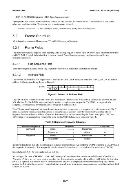
Release 199816<strong>3GPP</strong> <strong>TS</strong> 07.10 V7.2.0 (2002-03)<strong>TS</strong>0710_PORTNEG.indication (DLC, Line Status parameter)Description: The request primitive is used to send the line status to the remote device. The indication is sent to theother port emulation entity. The remote port emulation does not reply.Line status parameter= Port speed [no errors, overrun error, parity error, framing error]5.2 Frame StructureAll information transmitted between the TE and MS is conveyed in frames.5.2.1 Frame FieldsThe frame structure is composed of an opening and a closing flag, an Address field, a Control field, an Information fieldand FCS field. A length indication field is present in each frame if no transparency mechanism is used for themultiplexing session.5.2.1.1 Flag Sequence FieldEach frame begins and ends with a flag sequence octet which is defined as a constant bit pattern.5.2.1.2 Address FieldThe address field consists of a single octet. It contains the Data Link Connection Identifier (DLCI), the C/R bit and theaddress field extension bit as shown in Figure 2.Bit No. 1 2 3 4 5 6 7 8EA C/R D L C IFigure 2: Format of Address FieldThe DLCI is used to identify an individual user information stream as well as to identify connections between TE andMS. Multiple DLCIs shall be supported but the number is implementation-specific. The DLCIs are dynamicallyassigned. The values used for specific DLCIs are given in subclause 5.6.The C/R (command/response) bit identifies the frame as either a command or a response. In conformance with HDLCrules, a command frame contains the address of the data link connection entity to which it is transmitted while aresponse frame contains the address of the data link connection entity transmitting the frame. For a given DLC, theDLCI value of the address field remains the same but the C/R bit changes, as shown in Table 1.Table 1: Command/response bit usageCommand/response Direction C/R valueCommand Initiator ⎯⎯→ Responder 1Responder ⎯⎯→ Initiator 0Response Initiator ⎯⎯→ Responder 0Responder ⎯⎯→ Initiator 1Initiator is the station that take the initiative to initialize the multiplexer (i.e. sends the SABM command at DLCI 0 ) andthe responder is the station that accepts the initialization of the multiplexer (i.e. sends the UA response at DLCI 0)See subclause 5.4.3.1 for more details about C/R bit.According to the rules of ISO/IEC 13239:1997, the range of the address field may be extended by use of the EA bit.When the EA bit is set to 1 in an octet, it signifies that this octet is the last octet of the address field. When the EA bit isset to 0, it signifies that another octet of the address field follows. In the present document there is only one addressoctet so the EA bit is always set to 1. Note that future amendments to the present document may extend the address fieldand use the EA bit.<strong>3GPP</strong>


