

3GPP TS
3GPP TS
3GPP TS

Create successful ePaper yourself
Turn your PDF publications into a flip-book with our unique Google optimized e-Paper software.
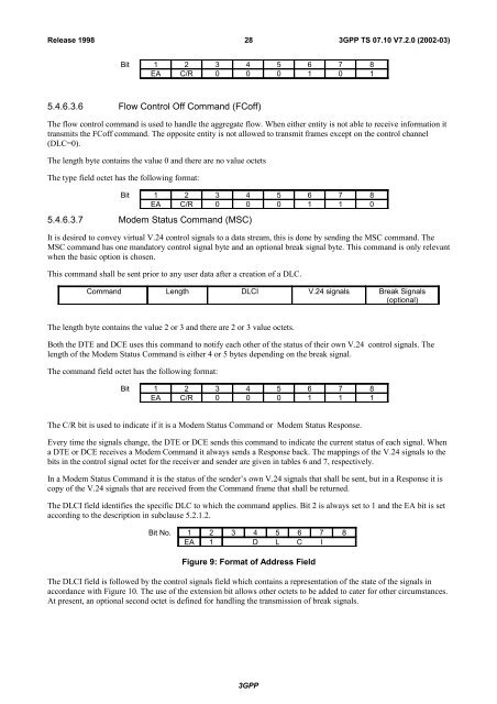
Release 199828<strong>3GPP</strong> <strong>TS</strong> 07.10 V7.2.0 (2002-03)Bit 1 2 3 4 5 6 7 8EA C/R 0 0 0 1 0 15.4.6.3.6 Flow Control Off Command (FCoff)The flow control command is used to handle the aggregate flow. When either entity is not able to receive information ittransmits the FCoff command. The opposite entity is not allowed to transmit frames except on the control channel(DLC=0).The length byte contains the value 0 and there are no value octetsThe type field octet has the following format:Bit 1 2 3 4 5 6 7 8EA C/R 0 0 0 1 1 05.4.6.3.7 Modem Status Command (MSC)It is desired to convey virtual V.24 control signals to a data stream, this is done by sending the MSC command. TheMSC command has one mandatory control signal byte and an optional break signal byte. This command is only relevantwhen the basic option is chosen.This command shall be sent prior to any user data after a creation of a DLC.Command Length DLCI V.24 signals Break Signals(optional)The length byte contains the value 2 or 3 and there are 2 or 3 value octets.Both the DTE and DCE uses this command to notify each other of the status of their own V.24 control signals. Thelength of the Modem Status Command is either 4 or 5 bytes depending on the break signal.The command field octet has the following format:Bit 1 2 3 4 5 6 7 8EA C/R 0 0 0 1 1 1The C/R bit is used to indicate if it is a Modem Status Command or Modem Status Response.Every time the signals change, the DTE or DCE sends this command to indicate the current status of each signal. Whena DTE or DCE receives a Modem Command it always sends a Response back. The mappings of the V.24 signals to thebits in the control signal octet for the receiver and sender are given in tables 6 and 7, respectively.In a Modem Status Command it is the status of the sender’s own V.24 signals that shall be sent, but in a Response it iscopy of the V.24 signals that are received from the Command frame that shall be returned.The DLCI field identifies the specific DLC to which the command applies. Bit 2 is always set to 1 and the EA bit is setaccording to the description in subclause 5.2.1.2.Bit No. 1 2 3 4 5 6 7 8EA 1 D L C IFigure 9: Format of Address FieldThe DLCI field is followed by the control signals field which contains a representation of the state of the signals inaccordance with Figure 10. The use of the extension bit allows other octets to be added to cater for other circumstances.At present, an optional second octet is defined for handling the transmission of break signals.<strong>3GPP</strong>


