Specifications - City of Montpelier, Vermont
Specifications - City of Montpelier, Vermont
Specifications - City of Montpelier, Vermont

Create successful ePaper yourself
Turn your PDF publications into a flip-book with our unique Google optimized e-Paper software.
Title:Project Manual<strong>Montpelier</strong> District Heating<strong>City</strong> <strong>of</strong> <strong>Montpelier</strong>, VTIssue Date:September 28, 2012Page #:1 <strong>of</strong> 1<strong>City</strong> <strong>of</strong> <strong>Montpelier</strong>39 Main Street<strong>Montpelier</strong>, VT 05602
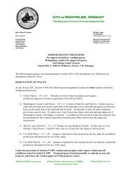
October 03, 2012CONSTRUCTION <strong>of</strong> a DISTRICT HEATING SYSTEM, HOT WATER CONVERSION AND CONNECTIONSCITY <strong>of</strong> MONTPELIER, VERMONTADVERTISEMENT FOR BIDSThe <strong>City</strong> <strong>of</strong> <strong>Montpelier</strong> is requesting bids for the construction <strong>of</strong> a district heating system withapproximately one mile <strong>of</strong> trench length <strong>of</strong> hot water piping, connections and conversions <strong>of</strong> three publicbuildings to use district heating water and several district heating service laterals to non"<strong>City</strong> controlledbuildings.Work to be performed under this contract consists <strong>of</strong> the construction <strong>of</strong> approximately one mile <strong>of</strong>trench including supply and return thin wall, carbon steel, pre"insulated district heating pipe, ranging from8” to 1.5” inside diameter in both system mains and service laterals. This new piping system will runbetween the State <strong>of</strong> <strong>Vermont</strong>’s heating plant, through <strong>City</strong> streets and extend to Union Elementary Schooland <strong>City</strong> Hall, with service laterals and spurs branching <strong>of</strong>f to serve non"<strong>City</strong> customers. The work includesrestoration <strong>of</strong> the surface conditions after pipe installation. In addition, this project includes converting theUnion Elementary from a low pressure steam heating system to a hot water heating system. Finally, thisproject includes connecting and converting the Police Department and the <strong>City</strong> Hall buildings to the districtheating system and modifying their internal heating systems to use the district hot water.Because the area <strong>of</strong> construction will be the <strong>City</strong> streets, the contract includes the reconstruction <strong>of</strong> thebituminous asphalt paved surfaces, concrete sidewalks, removal/reset <strong>of</strong> granite curbs, restoration <strong>of</strong> turfareas and related traffic control.Sealed bids will be received at the Office <strong>of</strong> the Director <strong>of</strong> Public Works, <strong>City</strong> Hall, 39 Main Street,<strong>Montpelier</strong>, VT 05602, until 10:00 am (Eastern) Thursday, November 01, 2012, at which place andtime, bids will be opened and publicly read aloud. Each sealed bid must be clearly marked “BID –<strong>Montpelier</strong> District Heating System.”Each bid must be accompanied by a certified check made payable to the <strong>City</strong> <strong>of</strong> <strong>Montpelier</strong> for fivepercent (5%) <strong>of</strong> the total amount <strong>of</strong> the bid. A bid bond may be used in lieu <strong>of</strong> a certified check. A 100%performance bond in the amount <strong>of</strong> the accepted base bid is required.PDF files <strong>of</strong> the complete contract documents and specifications can be downloaded for free from the<strong>City</strong> <strong>of</strong> <strong>Montpelier</strong> website. Paper copies <strong>of</strong> the complete contract documents and specifications are availableto interested parties for $150.00 (check only) at the following location:Public Works Office, <strong>City</strong> Hall39 Main Street<strong>Montpelier</strong>, VT802"223"9508._______________________________William Fraser, <strong>City</strong> Manager<strong>City</strong> <strong>of</strong> <strong>Montpelier</strong><strong>Montpelier</strong> District Heat SystemPage 1
CONSTRUCTION <strong>of</strong> a DISTRICT HEATING SYSTEM, HOT WATER CONVERSION AND CONNECTIONSCITY <strong>of</strong> MONTPELIER, VERMONTTABLE OF CONTENTSADVERTISEMENT FOR BIDS ............................................................................................................. 1TABLE OF CONTENTS ...................................................................................................................... 2INFORMATION FOR BIDDERS ........................................................................................................... 3BID BOND ..................................................................................................................................... 5NOTICE OF AWARD ......................................................................................................................... 6AGREEMENT .................................................................................................................................. 7PAYMENT BOND ............................................................................................................................. 9PERFORMANCE BOND .................................................................................................................... 11NOTICE TO PROCEED .................................................................................................................... 13CHANGE ORDER FORM .................................................................................................................. 14PAYMENT REQUEST FORM .............................................................................................................. 16GENERAL CONDITIONS ................................................................................................................. 17SCOPE OF WORK/MEASUREMENT & PAYMENT ................................................................................... 27BID FORM ................................................................................................................................ 76^CERTIFICATE OF SUBSTANTIAL COMPLETION ................................................................................ 84^CERTIFICATE OF FINAL COMPLETION AND ACCEPTANCE OF WORK ................................................... 86^PROJECT SPECIFICATIONS .......................................................................................................... 87^<strong>Montpelier</strong> District Heat SystemPage 2
INFORMATION FOR BIDDERSThe <strong>City</strong> <strong>of</strong> <strong>Montpelier</strong> will receive sealed bids for a Contract entitled “BID – <strong>Montpelier</strong> District HeatingSystem.” at the Office <strong>of</strong> the Director <strong>of</strong> Public Works, <strong>City</strong> Hall, 39 Main Street, <strong>Montpelier</strong>, VT 05602, until 10:00am (Eastern) Thursday, November 01, 2012.Preparation <strong>of</strong> BidsBids will be submitted in a sealed envelope clearly marked, “BID – <strong>Montpelier</strong> District Heating System.” onthe outside <strong>of</strong> the envelope, and delivered to the Office <strong>of</strong> the Director <strong>of</strong> Public Works, <strong>City</strong> Hall, 39 Main Street,<strong>Montpelier</strong>, <strong>Vermont</strong> 05602. The outside <strong>of</strong> the envelope shall also clearly bear the name and address <strong>of</strong> the bidder.All bids must be made on the required bid form. All blank spaces on the bid form must be fully completed andexecuted when submitted. Only one copy <strong>of</strong> the bid form is to be submitted.Any bid may be withdrawn prior to the duly scheduled time for the opening <strong>of</strong> bids. Any bid received after thetime and date specified shall not be considered.Site VisitPrior to the opening <strong>of</strong> Bids, it is assumed that each Bidder will have inspected the site area, the roadways, theplanned locations for service laterals, the <strong>City</strong> buildings to be connected to the system, adjacent properties andbecome thoroughly familiar with the Contract Documents, existing field conditions, and limitations. Bidders mustsatisfy themselves <strong>of</strong> the accuracy <strong>of</strong> the estimated quantities identified on the bid form by examination <strong>of</strong> the siteand review <strong>of</strong> the contract drawings and specifications. Failure <strong>of</strong> the Bidder to review all documents and fieldconditions pertinent to the Contract, including ADA compliance requirements, shall in no way relieve any Bidder fromthe obligation with respect to his/her Bid and the bidder shall not assert that there was a misunderstandingconcerning quantities or the nature <strong>of</strong> the work to be done.Bid Surety & Performance BondEach bid must be accompanied by a certified check payable to the owner for five percent <strong>of</strong> the total amount <strong>of</strong>the bid. As soon as the bid prices have been compared, the owner will return the certified checks <strong>of</strong> all except thethree lowest responsive, responsible bidders. When a contract agreement is executed, as authorized by the<strong>Montpelier</strong> <strong>City</strong> Council during a regularly scheduled meeting, the certified checks <strong>of</strong> the remaining unsuccessfulbidders will be returned. The certified check <strong>of</strong> the successful bidder will be retained until the contract agreementdocuments have been signed and the performance bond has been executed and approved, after which it will bereturned. A bid bond may be used in lieu <strong>of</strong> a certified check.The party to whom the contract is awarded will be required to execute the contract agreement and obtain theperformance bond within ten (10) calendar days from the date when the notice <strong>of</strong> award is delivered to the bidder.In case <strong>of</strong> failure <strong>of</strong> the bidder to execute the agreement, the owner may, at its option, consider the bidder indefault, in which case the bid bond or certified check accompanying the bid proposal shall become the property <strong>of</strong>the owner.The owner, within ten days <strong>of</strong> receipt <strong>of</strong> the bonds, shall sign the agreement, having first obtained authorizationfrom the <strong>Montpelier</strong> <strong>City</strong> Council. Should the owner not execute the agreement within such period, the bidder maynotify the owner in writing that the contract agreement will be withdrawn.Bodily Injury Liability and Property Damage Liability InsuranceThe Contractor shall take out and maintain during the life <strong>of</strong> this Contract such Comprehensive General BodilyInjury Liability and Property Damage Liability Insurance and Automobile Bodily Injury Liability and Property DamageLiability as shall protect him/her and any subcontractor performing work covered by this Contract for claims fordamages for personal injury, including accidental death, as well as from claims for property damage which may arisefrom operations under this Contract, whether such operations are performed by himself or by any subcontractor orby anyone directly or indirectly employed by either <strong>of</strong> them. The limits <strong>of</strong> liability for the above insurancerequirements and more detailed information are contained in the General Conditions attached hereto and made apart <strong>of</strong> here<strong>of</strong>.Award <strong>of</strong> ContractThe Contract will be awarded to the responsible and eligible Bidder submitting the lowest Bid, as determined bythe <strong>City</strong> per the current policy and subject to receipt <strong>of</strong> bonds as described above. The Contract will be awardedwithin thirty (30) days after the Bid receipt deadline unless a mutually agreed upon extension is established. The<strong>City</strong> may make such investigations as it deems necessary to determine the ability <strong>of</strong> the bidder to perform the workand the bidder shall furnish to the <strong>City</strong>, all such information and data for this purpose as the <strong>City</strong> may request. The<strong>City</strong> reserves the right to reject any or all Bids, or to waive any informalities or technicalities in any Bid in theinterest <strong>of</strong> the <strong>City</strong> and may reject any bid if the evidence obtained through the course <strong>of</strong> an investigation <strong>of</strong> a bidderfails to satisfy the <strong>City</strong> that the bidder is properly qualified to carry out the obligations <strong>of</strong> the agreement and tocomplete the work. A conditional or qualified bid will not be accepted.<strong>Montpelier</strong> District Heat SystemPage 3
The <strong>City</strong> also reserves the right to limit or extend the amount <strong>of</strong> work to be done due to budget limitations, orfor other reasons. (See also General Conditions.)Traffic & Pedestrian ControlThe Contractor will provide traffic control devices and will be responsible to provide traffic control personnelwhen required by the <strong>City</strong> and as determined by the job conditions. Reference is made to the “Manual <strong>of</strong> UniformTraffic Control Devices (MUTCD) F Traffic Control in Work Zones.” Special ADA compliant pedestrian detours aroundthe work zones will also be required. ^ The Contractor is solely responsible to maintain a safe work zone in fullcompliance with the MUTCD. Failure to do so may result in a written notification to discontinue work untilcompliance is achieved.The Contractor will coordinate all work on the <strong>City</strong> owned property with the <strong>City</strong>. Work on <strong>City</strong> and nonF<strong>City</strong>property will be conducted in a manner which minimizes interruption <strong>of</strong> facility operation as well as traffic into andout <strong>of</strong> the facility. Construction is to be conducted in a phased manner. The intent <strong>of</strong> the phasing is to allow thecontractor flexibility to complete the project as efficiently as possible while being sensitive to maintaining free use <strong>of</strong>the <strong>City</strong> streets for travel, commerce and recreation through the scheduled construction. It is understood thatportions <strong>of</strong> the <strong>City</strong> streets and sidewalks will have to be closed for a period <strong>of</strong> time. The contractor must maintainat least one access to businesses at all times during construction. The Contractor is to work with the <strong>City</strong> tomaintain a safe and secure work area while also allowing access to undisturbed or recently completed portions <strong>of</strong> theproject. Particular attention shall be paid to providing safety barricades, fencing and or walkways around excavatedareas to protect pedestrians from work area hazards. Protection <strong>of</strong> green concrete from damage or vandalism isentirely the Contractor’s responsibility. No additional compensation will be provided for any precautions taken by theContractor. Work hours within the <strong>City</strong> streets ^ will be limited to 7:00am – 3:30pm unless written permission isotherwise granted by the <strong>City</strong> or property owner.Testing Payment ProvisionsFor all compaction and leakage or other testing required by this contract, the Owner shall bear the cost <strong>of</strong> theinitial test. Should the initial test fail, the Contractor shall be responsible for all subsequent tests necessary todetermine that the tested installed item meets the project specifications.Termination <strong>of</strong> ContractThe Contract may be terminated by the <strong>City</strong> upon written notice to the Contractor on a specified date if theContractor:1. Fails to begin work within the specified time;2. Fails to pursue the work in a manner to ensure proper completion;3. Pursues the work in a manner to render the completed project unsuitable to the <strong>City</strong>;4. Discontinues work on the project.Commencement & Completion DatesThe project may be commenced upon issuance <strong>of</strong> a notification to proceed. The district heating system and inFbuilding conversions must be functional by September 30, 2013 with final completion by October 31, 2012. Thenotification to proceed shall be issued within ten (10) days from the execution <strong>of</strong> the agreement. Should there bereasons why the notice to proceed cannot be issued within such period, the issuance date may be negotiated bymutual agreement between the owner and contractor.The Contractor shall not commence work under this Contract until the insurance required hereunder has beenobtained, and such insurance has been approved by the <strong>City</strong>; nor shall the Contractor allow any subcontractor tocommence work on his subcontract until all similar insurance required <strong>of</strong> the subcontractor has been so obtained andapproved. Approval <strong>of</strong> the insurance by the <strong>City</strong> shall not relieve or decrease the liability <strong>of</strong> the Contractorhereunder. (See also General Conditions.)<strong>Montpelier</strong> District Heat SystemPage 4
BID BONDKNOW ALL MEN BY THESE PRESENTS, that we, the undersigned, ____________________ as Principal, and________________________________ as Surety, are hereby held and firmly bound unto____________________________ as OWNER in the penal sum <strong>of</strong> ___________________________ for thepayment <strong>of</strong> which, well and truly to be made, we hereby jointly and severally bind ourselves, successors andassigns.Signed, this ________ day <strong>of</strong> ____, 20 . The Condition <strong>of</strong> the above obligation is such that whereas thePrincipal has submitted to ____________________________________ a certain BID,attached hereto and hereby made a part here<strong>of</strong> to enter into a contract in writing, for the____________________________________________________________________________________________________________________________________________________________________NOW, THEREFORE,(a)If said BID shall be rejected, or(b) If said BID shall be accepted and the Principal shall execute and deliver a contract in the Form <strong>of</strong>Contract attached hereto (properly completed in accordance with said BID) and shall furnish a BOND for hisfaithful performance <strong>of</strong> said contract, and for the payment <strong>of</strong> all persons performing labor or furnishingmaterials in connection therewith, and shall in all other respects perform the agreement created by theacceptance <strong>of</strong> said BID, then this obligation shall be void, otherwise the same shall remain in force andeffect, it being expressly understood and agreed that the liability <strong>of</strong> the Surety for any and all claimshereunder shall, in no event, exceed the penal amount <strong>of</strong> this obligation as herein stated.The Surety, for value received, hereby stipulates and agrees that the obligations <strong>of</strong> said Surety and its BOND shallbe in no way impaired or affected by any extension <strong>of</strong> the time within which the OWNER may accept such BID; andsaid Surety does hereby waive notice <strong>of</strong> any such extension.IN WITNESS WHEREOF, the Principal and the Surety have hereunto set their hands and seals, and such <strong>of</strong> them asare corporations have caused their corporate seals to be hereto affixed and these presents to be signed by theirproper <strong>of</strong>ficers, the day and year first set forth above.______________________________ (L.S.)Principal_______________________________________SuretyBy:__________________________IMPORTANT F Surety companies executing BONDS must appear on the Treasury Department's most current list(Circular 570 as amended) and be authorized to transact business in the state where the project is located.<strong>Montpelier</strong> District Heat SystemPage 5
NOTICE OF AWARDTO:______________________________________________________________________________PROJECT Description:__________________________________________________________________________________________________________________________________________________________________________The OWNER has considered the BID submitted by you for the above described WORK in response to itsADVERTISEMENT FOR BIDS dated _____________, 20 , and Information for Bidders.You are hereby notified that your BID has been accepted for items in the amount <strong>of</strong> $_________________.You are required by the Information for Bidders to execute the Agreement and furnish the required CONTRACTOR'SPerformance BOND, Payment BOND and certificates <strong>of</strong> insurance within ten (10) calendar days from the date <strong>of</strong> thisNOTICE to you.If you fail to execute said Agreement and to furnish said BONDS within ten (10) days from the date <strong>of</strong> this NOTICE,said OWNER will be entitled to consider all your rights arising out <strong>of</strong> the OWNER'S acceptance <strong>of</strong> your BID asabandoned and as a forfeiture <strong>of</strong> your BID BOND. The OWNER will be entitled to such other rights as may begranted by law.You are required to return an acknowledged copy <strong>of</strong> this NOTICE TO AWARD to the OWNER.Dated this ____ day <strong>of</strong> ____, 20 .__________________________________________ ByOwner__________________________Title_________________________ACCEPTANCE OF NOTICEReceipt <strong>of</strong> the above NOTICE OF AWARD is hereby acknowledgedby ________________________________________________this ____ day <strong>of</strong> ____, 20 .By _____________________________________Title ____________________________________<strong>Montpelier</strong> District Heat SystemPage 6
AGREEMENTTHIS AGREEMENT, made this ______ day <strong>of</strong> ____________, 20___, by and between____________________________________, hereinafter called "OWNER" and____________________________________ doing business as (an individual, a partnership or a corporation)hereinafter called "CONTRACTOR".WITNESSETH: That for and in consideration <strong>of</strong> the payments and agreements hereinafter mentioned:1. The CONTRACTOR will commence and complete the construction <strong>of</strong> the <strong>Montpelier</strong> District Heating System.2. The CONTRACTOR will furnish all the material, supplies, tools, equipment, labor and other services necessaryfor the construction and completion <strong>of</strong> the PROJECT described herein.3. The CONTRACTOR will commence the WORK required by the CONTRACT DOCUMENTS on the date <strong>of</strong> issuance<strong>of</strong> the NOTICE TO PROCEED and will complete the same by September 30, 2013 unless the period forcompletion is extended otherwise by the CONTRACT DOCUMENTS. The CONTRACTOR acknowledges that thedate <strong>of</strong> beginning and the time for completion <strong>of</strong> the WORK are essential conditions <strong>of</strong> the CONTRACTDOCUMENTS and the CONTRACTOR further agrees to pay as liquidated damages, the sum <strong>of</strong> $__________ foreach consecutive calendar day that the CONTRACTOR shall be in default after the time specified in theAgreement and as provided in Section 15 <strong>of</strong> the General Conditions.4. The CONTRACTOR agrees to perform all the WORK described in the CONTRACT DOCUMENTS and comply withthe terms therein for the sum <strong>of</strong> $____________________ or as shown in the BID schedule.5. The term "CONTRACT DOCUMENTS" means and includes the following:(A) Advertisement for BIDS(B) Information for BIDDERS(C) BID(D) BID BOND(E) Agreement(F) General Conditions(G) Supplemental General Conditions(H) Payment BOND(I) Performance BOND(J) NOTICE OF AWARD(K) NOTICE TO PROCEED(L) CHANGE ORDER(M) DRAWINGS prepared by ________________________________ numbered __________through __________, and dated __________, 20___.(N) SPECIFICATIONS prepared or issued by _______________________________________,and dated __________, 20___.(O) ADDENDA:No. __________, dated __________, 20___.No. __________, dated __________, 20___.No. __________, dated __________, 20___.No. __________, dated __________, 20___.6. The OWNER will pay to the CONTRACTOR in the manner and at such times as set forth in the GeneralConditions such amounts as required by the CONTRACT DOCUMENTS.7. This Agreement shall be binding upon all parties hereto and their respective heirs, executors, administrators,<strong>Montpelier</strong> District Heat SystemPage 7
successors, and assigns.IN WITNESS WHEREOF, the parties hereto have executed, or caused to be executed by their duly authorized<strong>of</strong>ficials, this Agreement in ____ copies, each <strong>of</strong> which shall be deemed an original on the date first above written.OWNER: ________________________________ ATTEST: ____________________________________(Signature)BY: ____________________________________ Name: ______________________________________(Signature)(Please print)Name: __________________________________(Please print)(Seal)Title: ___________________________________ Title: _______________________________________CONTRACTOR: __________________________BY: ____________________________________(Signature)Name: __________________________________(Please print)(Contractor Seal)Address: ________________________________________________________________________________________________________________Phone #ATTEST: ________________________________(Signature)Name: __________________________________(Please print)Title: ___________________________________<strong>Montpelier</strong> District Heat SystemPage 8
PAYMENT BONDKNOW ALL MEN BY THESE PRESENTS THAT:______________________________________________________________________________________(Name <strong>of</strong> Contractor)_____________________________________________________________________________________(Address <strong>of</strong> Contractor)a ____________________________________, hereinafter called Principal,(Corporation, Partnership or Individual)and_______________________________________________________________________________________(Name <strong>of</strong> Surety)_____________________________________________________________________________________(Address <strong>of</strong> Surety)hereinafter called Surety, are held and firmly bound unto The <strong>City</strong> <strong>of</strong> <strong>Montpelier</strong>, <strong>City</strong> Hall, 39 Main Street,<strong>Montpelier</strong>, <strong>Vermont</strong> 05602 hereinafter called OWNER, in the penal sum <strong>of</strong> ____________________________________________________________ Dollars, $(___________________) in lawful money <strong>of</strong> the United States,for the payment <strong>of</strong> which sum well and truly to be made, we bind ourselves, successors, and assigns, jointly andseverally, firmly by these presents.THE CONDITION OF THIS OBLIGATION is such that whereas, the Principal entered into a certain contract with theOWNER, dated the _____ day <strong>of</strong> _______________________, 20_____, a copy <strong>of</strong> which is hereto attached andmade a part here<strong>of</strong> for the construction <strong>of</strong> the <strong>Montpelier</strong> District Heating System.NOW, THEREFORE, if the Principal shall promptly make payment to all persons, firms, SUBCONTRACTORS, andcorporations furnishing materials for or performing labor in the prosecution <strong>of</strong> the WORK provided for in suchcontract, and any authorized extension or modification there<strong>of</strong>, including all amounts due for materials, lubricants,oil, gasoline, coal and coke, repairs on machinery, equipment and tools, consumed or used in connection with theconstruction <strong>of</strong> such WORK and all insurance premiums on said WORK, and for all labor performed in such WORKwhether by SUBCONTRACTOR or otherwise, then this obligation shall be void; otherwise to remain in force andeffect.PROVIDED, FURTHER, that the said Surety for value received hereby stipulates and agrees that no change,extension <strong>of</strong> time, alteration or addition to the terms <strong>of</strong> the contract or to the WORK to be performed hereunder orthe SPECIFICATIONS accompanying the same shall in any wise affect its obligation on this BOND, and it does herebywaive notice <strong>of</strong> any such change, extension <strong>of</strong> time, alteration or addition to the terms <strong>of</strong> the contract or to theWORK or to the SPECIFICATIONS.PROVIDED, FURTHER, that no final settlement between the OWNER and the CONTRACTOR shall abridge the right <strong>of</strong>any beneficiary hereunder, whose claim may be unsatisfied.IN WITNESS WHEREOF, this instrument is executed in _____ counterparts, each one <strong>of</strong> which shall be deemedan original, this the _____ day <strong>of</strong> _______________________, 20_____.<strong>Montpelier</strong> District Heat SystemPage 9
ATTEST:____________________________(Principal Secretary)By:_________________________________(s)____________________________________Principal’s Printed Name(Seal)Address: ____________________________________________________________________________________________________Witness as to Principal____________________________Address________________________________________________________________SuretyATTEST:By: ____________________________________AttorneyFinFFact____________________________Witness as to Surety________________________________________________________Address: ________________________________________________________________________________________________________________________________________AddressNOTE: Date <strong>of</strong> BOND must not be prior to date <strong>of</strong> Contract. If CONTRACTOR is Partnership, all partners shouldexecute BOND.IMPORTANT: Surety companies executing BONDS must appear on the Treasury Department's most current list(Circular 570) as amended and be authorized to transact business in the State where the PROJECT is located.<strong>Montpelier</strong> District Heat SystemPage 10
PERFORMANCE BONDKNOW ALL MEN BY THESE PRESENTS THAT:_________________________________________________________________________________________(Name <strong>of</strong> Contractor)_________________________________________________________________________________________(Address <strong>of</strong> Contractor)a ____________________________________, hereinafter called Principal, and(Corporation, Partnership or Individual)_________________________________________________________________________________________(Name <strong>of</strong> Surety)_________________________________________________________________________________________(Address <strong>of</strong> Surety)hereinafter called Surety, are held and firmly bound unto the <strong>City</strong> <strong>of</strong> <strong>Montpelier</strong>, <strong>Vermont</strong> (herinafter calledOWNER) <strong>City</strong> Hall, 39 Main Street, <strong>Montpelier</strong>, <strong>Vermont</strong>, in the penal sum <strong>of</strong>___________________________________________ ______________________ Dollars, $(_________________)in lawful money <strong>of</strong> the United States, for the payment <strong>of</strong> which sum well and truly to be made, we bind ourselves,successors, and assigns, jointly and severally, firmly by these presents.THE CONDITION OF THIS OBLIGATION is such that whereas, the Principal entered into a certain contract with theOWNER, dated the _____ day <strong>of</strong> _______________________, 20_____, a copy <strong>of</strong> which is hereto attached andmade a part here<strong>of</strong> for the construction <strong>of</strong> the <strong>Montpelier</strong> District Heating System.NOW, THEREFORE, if the principal shall well, truly and faithfully perform its duties, all the undertakings, covenants,terms, conditions and agreements <strong>of</strong> said contract during the original term there<strong>of</strong>, and any extensions there<strong>of</strong>which may be granted by the OWNER, with or without notice to the Surety and during the one year guaranty period,and if he shall satisfy all claims and demands incurred under such contract, and shall fully indemnify and saveharmless the OWNER from all costs and damages which it may suffer by reason <strong>of</strong> failure to do so, and shallreimburse and repay the OWNER all outlay and expense which the OWNER may incur in making good any default,then this obligation shall be void; otherwise to remain in full force and effect.PROVIDED, FURTHER, that the said Surety for value received hereby stipulates and agrees that no change,extension <strong>of</strong> time, alteration or addition to the terms <strong>of</strong> the contract or to the WORK to be performed hereunder orthe SPECIFICATIONS accompanying the same shall in any wise affect its obligation on this BOND, and it does herebywaive notice <strong>of</strong> any such change, extension <strong>of</strong> time, alteration or addition to the terms <strong>of</strong> the contract or to theWORK or to the SPECIFICATIONS.PROVIDED, FURTHER, that no final settlement between the OWNER and the CONTRACTOR shall abridge the right <strong>of</strong>any beneficiary hereunder, whose claim may be unsatisfied.IN WITNESS WHEREOF, this instrument is executed in _____ counterparts, each one <strong>of</strong> which shall be deemed anoriginal, this the _____ day <strong>of</strong> _______________________, 20_____.ATTEST:________________________________________________________________(Principal Secretary)_________________________________(s)By:Principal’s Printed Name(Seal)____________________________Address: ________________________________________________________________________<strong>Montpelier</strong> District Heat SystemPage 11
Witness as to Principal____________________________Address________________________________________________________________SuretyATTEST:By: ____________________________________AttorneyFinFFact____________________________Witness as to Surety________________________________________________________Address: ________________________________________________________________________________________________________________________________________AddressNOTE: Date <strong>of</strong> BOND must not be prior to date <strong>of</strong> Contract. If CONTRACTOR is Partnership, all partners shouldexecute BOND.IMPORTANT: Surety companies executing BONDS must appear on the Treasury Department's most current list(Circular 570) as amended and be authorized to transact business in the State where the PROJECT is located.<strong>Montpelier</strong> District Heat SystemPage 12
NOTICE TO PROCEEDTo: ___________________________(Contractor)___________________________Date <strong>of</strong> Issuance: __________________Project: __________________________________________________________________________________________________________________________________________________________________You are hereby notified to commence all WORK on this date in accordance with the Agreement dated__________________,20____. The date <strong>of</strong> completion <strong>of</strong> all WORK is ______________________, 20____.____________________________________(Owner)By: ____________________________________Title: ____________________________________Receipt <strong>of</strong> the above NOTICE TO PROCEEDACCEPTANCE OF NOTICEis hereby acknowledged by _______________________________________________________________,this the ____ day <strong>of</strong> ________________, 20___(Name <strong>of</strong> Contractor)By:_________________________________________(Printed or Typed Name)By:_________________________________________(Signature)Title: _______________________________________<strong>Montpelier</strong> District Heat SystemPage 13
CHANGE ORDER # _________CHANGE ORDER FORMProject No. ___________________Contract No. __________________CONTRACT TITLE: ______________________________________OWNER: _______________________________________________CONTRACTOR: _________________________________________Date: _______________________Agreement Date:________________ORIGINAL PRICE: $________________Original Completion Date: ___________The following changes are hereby made to the CONTRACT DOCUMENTS:DESCRIPTION:JUSTIFICATION:PRICE: This C.O. (1) will (not change/increase/decrease)the Contract Price By:Current Contract Price per most recent C.O.:The new Contract Price including this C.O. is:$____________$____________$____________TIME: Current Contract Calendar Days as per most recent C.O.:DAYS _____This C.O. will (not change/increase/decrease)the Contract Calendar Days by:The new Contract Calendar Days including this C.O. is:The new Contract Completion Date is, therefore:DAYS _____DAYS _________________________The attached Contractor's Revised Project Schedule reflects increases or decreases in Contract Time as authorized bythis C.O.Stipulated price and time adjustment includes all costs and time associated with the above described change.Contractor waives all rights for additional compensation or time extension for said change. Contractor and Owneragree that the price(s) and time adjustment(s) stated above are equitable and acceptable to both parties.REQUESTED BY: __SIGNATURES/APPROVALS:<strong>Montpelier</strong> District Heat SystemPage 14
Recommended By:(Engineer)Accepted By:(Contractor)Ordered By:(Owner)(1) C.O. means Change Order<strong>Montpelier</strong> District Heat SystemPage 15
PAYMENT REQUEST FORM<strong>Montpelier</strong> District Heat SystemPage 16
GENERAL CONDITIONS1. Definitions 16. Correction <strong>of</strong> Work2. Additional Instructions & Detail Drawings 17. Subsurface Conditions3. Schedules, Reports and Records 18. Suspension <strong>of</strong> Work, Termination & Delay4. Drawings and <strong>Specifications</strong> 19. Payments to Contractor5. Shop Drawings 20. Acceptance <strong>of</strong> Final Payment as Release6. Materials, Services and Facilities 21. Insurance7. Inspection and Testing 22. Contract Security8. Substitutions 23. Assignments9. Patents 24. Indemnification10. Surveys, Permits, Regulations 25. Separate Contracts11. Protection <strong>of</strong> Work, Property, Persons 26. Subcontracting12. Supervision by Contractor 27. Engineer's Authority13. Changes in the Work 28. Land and Rights3<strong>of</strong>3Way14. Changes in Contract Price 29. Guaranty15. Time for Completion & Liquidated Damages 30. Taxes1. DEFINITIONS1.1. Wherever used in the CONTRACT DOCUMENTS, the following terms shall have the meanings indicated which shall beapplicable to both the singular and plural there<strong>of</strong>:1.2. ADDENDA 3 Written or graphic instruments issued prior to the execution <strong>of</strong> the Agreement which modify or interpret theCONTRACT DOCUMENTS, DRAWINGS and SPECIFICATIONS, by additions, deletions, clarifications or corrections.1.3. BID 3 The <strong>of</strong>fer or proposal <strong>of</strong> the BIDDER submitted on the prescribed form setting forth the prices for the WORK to beperformed.1.4. BIDDER 3 Any person, firm or corporation submitting a BID for the WORK.1.5. BONDS 3 Bid, Performance, and Payment Bonds and other instruments <strong>of</strong> security, furnished by the CONTRACTOR andhis surety in accordance with the CONTRACT DOCUMENTS.1.6. CHANGE ORDER 3 A written order to the CONTRACTOR authorizing an addition, deletion or revision in the WORK withinthe general scope <strong>of</strong> the CONTRACT DOCUMENTS, or authorizing an adjustment in the CONTRACT PRICE or CONTRACTTIME.1.7. CONTRACT DOCUMENTS 3 The contract, including Advertisement For Bids, Information For Bidders, BID, Bid Bond,Agreement, Payment Bond, Performance Bond, NOTICE OF AWARD, NOTICE TO PROCEED, CHANGE ORDER,DRAWINGS, SPECIFICATIONS, and ADDENDA.1.8. CONTRACT PRICE 3 The total monies payable to the CONTRACTOR under the terms and conditions <strong>of</strong> the CONTRACTDOCUMENTS.1.9. CONTRACT TIME 3 The number <strong>of</strong> calendar days stated in the CONTRACT DOCUMENTS for the completion <strong>of</strong> theWORK.1.10. CONTRACTOR 3 The person, firm or corporation with whom the OWNER has executed the Agreement.1.11. DRAWINGS 3 The part <strong>of</strong> the CONTRACT DOCUMENTS which show the characteristics and scope <strong>of</strong> the WORK to beperformed and which have been prepared or approved by the ENGINEER.1.12. ENGINEER 3 The person, firm or corporation named as such in the CONTRACT DOCUMENTS.1.13. FIELD ORDER 3 A written order effecting a change in the WORK not involving an adjustment in the CONTRACT PRICE oran extension <strong>of</strong> the CONTRACT TIME, issued by the ENGINEER to the CONTRACTOR during construction.1.14. NOTICE OF AWARD 3 The written notice <strong>of</strong> the acceptance <strong>of</strong> the BID from the OWNER to the successful BIDDER.1.15. NOTICE TO PROCEED 3 Written communication issued by the OWNER to the CONTRACTOR authorizing him to proceedwith the WORK and establishing the date <strong>of</strong> commencement <strong>of</strong> the WORK.1.16. OWNER 3 A public or quasi3public body or authority, corporation, association, partnership, or individual for whom theWORK is to be performed.<strong>Montpelier</strong> District Heat SystemPage 17
1.17. PROJECT 3 The undertaking to be performed as provided in the CONTRACT DOCUMENTS.1.18. RESIDENT PROJECT REPRESENTATIVE 3 The authorized representative <strong>of</strong> the OWNER who is assigned to thePROJECT site or any part there<strong>of</strong>.1.19. SHOP DRAWINGS 3 All drawings, diagrams, illustrations, brochures, schedules and other data which are prepared by theCONTRACTOR, a SUBCONTRACTOR, manufacturer, SUPPLIER or distributor, which illustrate how specific portions <strong>of</strong> theWORK shall be fabricated or installed.1.20. SPECIFICATIONS 3 A part <strong>of</strong> the CONTRACT DOCUMENTS consisting <strong>of</strong> written descriptions <strong>of</strong> a technical nature <strong>of</strong>materials, equipment, construction systems, standards and workmanship.1.21. SUBCONTRACTOR 3 An individual, firm or corporation having a direct contract with the CONTRACTOR or with any otherSUBCONTRACTOR for the performance <strong>of</strong> a part <strong>of</strong> the WORK at the site.1.22. SUBSTANTIAL COMPLETION 3 That date as certified by the ENGINEER when the construction <strong>of</strong> the PROJECT or aspecified part there<strong>of</strong> is sufficiently completed, in accordance with the CONTRACT DOCUMENTS, so that the PROJECT orspecified part can be utilized for the purposes for which it is intended.1.23. SUPPLEMENTAL GENERAL CONDITIONS 3 Modifications to General Conditions required by a Federal agency forparticipation in the PROJECT and approved by the agency in writing prior to inclusion in the CONTRACT DOCUMENTS, or suchrequirements that may be imposed by applicable state laws.1.24. SUPPLIER 3 Any person or organization who supplies materials or equipment for the WORK, including that fabricated to aspecial design, but who does not perform labor at the site.1.25. WORK 3 All labor necessary to produce the construction required by the CONTRACT DOCUMENTS, and all materials andequipment incorporated or to be incorporated in the PROJECT.1.26. WRITTEN NOTICE 3 Any notice to any party <strong>of</strong> the Agreement relative to any part <strong>of</strong> this Agreement in writing andconsidered delivered and the service there<strong>of</strong> completed, when posted by certified or registered mail to the said party at his lastgiven address, or delivered in person to said party or his authorized representative on the WORK.2. ADDITIONAL INSTRUCTION AND DETAIL DRAWINGS2.1. The CONTRACTOR may be furnished additional instructions and detail drawings, by the ENGINEER, as necessary tocarry out the WORK required by the CONTRACT DOCUMENTS.2.2. The additional drawings and instruction thus supplied will become a part <strong>of</strong> the CONTRACT DOCUMENTS. TheCONTRACTOR shall carry out the WORK in accordance with the additional detail drawings and instructions.3. SCHEDULES, REPORTS AND RECORDS3.1. The CONTRACTOR shall submit to the OWNER such schedule <strong>of</strong> quantities and costs, progress schedules, payrolls,reports, estimates, records and other data where applicable as are required by the CONTRACT DOCUMENTS for theWORK to be performed.3.2. Prior to the first partial payment estimate the CONTRACTOR shall submit construction progress schedules showing theorder in which he proposes to carry on the WORK, including dates at which he will start the various parts <strong>of</strong> the WORK,estimated date <strong>of</strong> completion <strong>of</strong> each part and, as applicable:3.2.1. The dates at which special detail drawings will be required; and3.2.2. Respective dates for submission <strong>of</strong> SHOP DRAWINGS, the beginning <strong>of</strong> manufacture, the testing and the installation<strong>of</strong> materials, supplies and equipment.3.3. The CONTRACTOR shall also submit a schedule <strong>of</strong> payments that he anticipates he will earn during the course <strong>of</strong> theWORK.4. DRAWINGS AND SPECIFICATIONS4.1. The intent <strong>of</strong> the DRAWINGS and SPECIFICATIONS is that the CONTRACTOR shall furnish all labor, materials, tools,equipment, and transportation necessary for the proper execution <strong>of</strong> the WORK in accordance with the CONTRACTDOCUMENTS and all incidental work necessary to complete the PROJECT in an acceptable manner, ready for use,occupancy or operation by the OWNER.4.2. In case <strong>of</strong> conflict between the DRAWINGS and SPECIFICATIONS, the SPECIFICATIONS shall govern. Figuredimensions on DRAWINGS shall govern over scale dimensions, and detailed DRAWINGS shall govern over generalDRAWINGS.4.3. Any discrepancies found between the DRAWINGS and SPECIFICATIONS and site conditions or and inconsistencies orambiguities in the DRAWINGS or SPECIFICATIONS shall be immediately reported to the ENGINEER, in writing, who shallpromptly correct such inconsistencies or ambiguities in writing. WORK done by the CONTRACTOR after his discovery <strong>of</strong>such discrepancies, inconsistencies or ambiguities shall be done at the CONTRACTOR's risk.5. SHOP DRAWINGS5.1. The CONTRACTOR shall provide SHOP DRAWINGS as may be necessary for the prosecution <strong>of</strong> the WORK as required<strong>Montpelier</strong> District Heat SystemPage 18
y the CONTRACT DOCUMENTS. The ENGINEER shall promptly review all SHOP DRAWINGS. The ENGINEER'Sapproval <strong>of</strong> any SHOP DRAWING shall not release the CONTRACTOR from responsibility for deviations from theCONTRACT DOCUMENTS. The approval <strong>of</strong> any SHOP DRAWING, which substantially deviates from the requirement <strong>of</strong>the CONTRACT DOCUMENTS, shall be evidenced by a CHANGE ORDER.5.2. When submitted for the ENGINEER'S review, SHOP DRAWINGS shall bear the CONTRACTOR'S certification that he hasreviewed, checked and approved the SHOP DRAWINGS and that they are in conformance with the requirements <strong>of</strong> theCONTRACT DOCUMENTS.5.3. Portions <strong>of</strong> the WORK requiring a SHOP DRAWING or sample submission shall not begin until the SHOP DRAWING orsubmission has been approved by the ENGINEER. A copy <strong>of</strong> each approved SHOP DRAWING and each approvedsample shall be kept in good order by the CONTRACTOR at the site and shall be available to the ENGINEER.6. MATERIALS, SERVICES AND FACILITIES6.1. It is understood that, except as otherwise specifically stated in the CONTRACT DOCUMENTS, the CONTRACTOR shallprovide and pay for all materials, labor, tools, equipment, water, light, power, transportation, supervision, temporaryconstruction <strong>of</strong> any nature, and all other services and facilities <strong>of</strong> any nature whatsoever necessary to execute, complete,and deliver the WORK within the specified time.6.2. Materials and equipment shall be so stored as to insure the preservation <strong>of</strong> their quality and fitness for the WORK. Storedmaterials and equipment to be incorporated in the WORK shall be located so as to facilitate prompt inspection.6.3. Manufactured articles, materials and equipment shall be applied, installed, connected, erected, used, cleaned andconditioned as directed by the manufacturer.6.4. Materials, supplies and equipment shall be in accordance with samples submitted by the CONTRACTOR and approved bythe ENGINEER.6.5. Materials, supplies or equipment to be incorporated into the WORK shall not be purchased by the CONTRACTOR or theSUBCONTRACTOR subject to a chattel mortgage or under a conditional sale contract or other agreement by which aninterest is retained by the seller.7. INSPECTION AND TESTING7.1. All materials and equipment used in the construction <strong>of</strong> the PROJECT shall be subject to adequate inspection and testingin accordance with generally accepted standards, as required and defined in the CONTRACT DOCUMENTS.7.2. The OWNER shall provide all inspection and testing services not required by the CONTRACT DOCUMENTS.7.3. The CONTRACTOR shall provide at his expense the testing and inspection services required by the CONTRACTDOCUMENTS.7.4. If the CONTRACT DOCUMENTS, laws, ordinances, rules, regulations or orders <strong>of</strong> any public authority having jurisdictionrequire any WORK to specifically be inspected, tested, or approved by someone other than the CONTRACTOR, theCONTRACTOR will give the ENGINEER timely notice <strong>of</strong> readiness. The CONTRACTOR will then furnish the ENGINEERthe required certificates <strong>of</strong> inspection, testing or approval.7.5. Inspections, tests or approvals by the engineer or others shall not relieve the CONTRACTOR from his obligations toperform the WORK in accordance with the requirements <strong>of</strong> the CONTRACT DOCUMENTS.7.6. The ENGINEER and his representatives will at all times have access to the WORK. In addition, authorized representativesand agents <strong>of</strong> any participating Federal or State agency shall be permitted to inspect all work, materials, payrolls, records <strong>of</strong>personnel, invoices <strong>of</strong> materials, and other relevant data and records. The CONTRACTOR will provide proper facilities forsuch access and observation <strong>of</strong> the WORK and also for any inspection, or testing there<strong>of</strong>.7.7. If any WORK is covered contrary to the written instructions <strong>of</strong> the ENGINEER it must, if requested by the ENGINEER, beuncovered for his observation and replaced at the CONTRACTOR'S expense.7.8. If the ENGINEER considers it necessary or advisable that covered WORK be inspected or tested by others, theCONTRACTOR, at the ENGINEER'S request, will uncover, expose or otherwise make available for observation, inspectionor testing as the ENGINEER may require, that portion <strong>of</strong> the WORK in questions, furnishing all necessary labor, materials,tools, and equipment. If it is found that such WORK is defective, the CONTRACTOR will bear all the expenses <strong>of</strong> suchuncovering, exposure, observation, inspection and testing and <strong>of</strong> satisfactory reconstruction. If, however, such WORK isnot found to be defective, the CONTRACTOR will be allowed an increase in the CONTRACT PRICE or an extension <strong>of</strong> theCONTRACT TIME, or both, directly attributable to such uncovering, exposure, observation, inspection, testing andreconstruction and an appropriate CHANGE ORDER shall be issued.8. SUBSTITUTIONS8.1. Whenever a material, article or piece <strong>of</strong> equipment is identified on the DRAWINGS or SPECIFICATIONS by reference tobrand name or catalog number, it shall be understood that this is referenced for the purpose <strong>of</strong> defining the performance orother salient requirements and that other products <strong>of</strong> equal capacities, quality and function shall be considered. TheCONTRACTOR may recommend the substitution <strong>of</strong> a material, article, or piece <strong>of</strong> equipment <strong>of</strong> equal substance andfunction for those referred to in the CONTRACT DOCUMENTS by reference to brand name or catalog number, and if, inthe opinion <strong>of</strong> the ENGINEER, such material, article, or piece <strong>of</strong> equipment is <strong>of</strong> equal substance and function to thatspecified, the ENGINEER may approve its substitution and use by the CONTRACTOR. Any cost differential shall bedeductible from the CONTRACT PRICE and the CONTRACT DOCUMENTS shall be appropriately modified by CHANGEORDER. The CONTRACTOR warrants that if substitutes are approved, no major changes in the function or general design<strong>Montpelier</strong> District Heat SystemPage 19
9. PATENTS<strong>of</strong> the PROJECT will result. Incidental changes or extra component parts required to accommodate the substitute will bemade by the CONTRACTOR without a change in the CONTRACT PRICE or CONTRACT TIME.9.1. The CONTRACTOR shall pay all applicable royalties and license fees. He shall defend all suits or claims for infringement<strong>of</strong> any patent rights and save the OWNER harmless from loss on account there<strong>of</strong>, except that the OWNER shall beresponsible for any such loss when a particular process, design, or the product <strong>of</strong> a particular manufacturer ormanufacturers is specified, however, if the CONTRACTOR has reason to believe that the design, process or productspecified is an infringement <strong>of</strong> a patent, he shall be responsible for such loss unless he promptly gives such information tothe ENGINEER.10. SURVEYS, PERMITS, REGULATIONS10.1. The OWNER shall furnish all boundary surveys and establish all base lines for locating the principal component parts <strong>of</strong> theWORK together with a suitable number <strong>of</strong> bench marks adjacent to the WORK as shown in the CONTRACTDOCUMENTS. From the information provided by the OWNER, unless otherwise specified in the CONTRACTDOCUMENTS, the CONTRACTOR shall develop and make all detail surveys needed for construction such as slopestakes, batter boards, stakes for pile locations and other working points, lines, elevations and cut sheets.10.2. The CONTRACTOR shall carefully preserve bench marks, reference points and stakes and, in case <strong>of</strong> willful or carelessdestruction, he shall be charged with the resulting expense and shall be responsible for any mistake that may be caused bytheir unnecessary loss or disturbance.10.3. Permits and licenses <strong>of</strong> a temporary nature necessary for the prosecution <strong>of</strong> the WORK shall be secured and paid for bythe CONTRACTOR unless otherwise stated in the SUPPLEMENTAL GENERAL CONDITIONS. Permits, licenses andeasements for permanent structures or permanent changes in existing facilities shall be secured and paid for by theOWNER, unless otherwise specified. The CONTRACTOR shall give all notices and comply with all laws, ordinances, rulesand regulations bearing on the conduct <strong>of</strong> the WORK as drawn and specified. If the CONTRACTOR observes that theCONTRACT DOCUMENTS are at variance therewith, he shall promptly notify the ENGINEER in writing, and any necessarychanges shall be adjusted as provided in Section 13, CHANGES IN THE WORK.^ 10.4. The OWNER will obtain the CONSTRUCTION GENERAL PERMIT from the <strong>Vermont</strong> Agency <strong>of</strong> NaturalResources.11. PROTECTION OF WORK, PROPERTY AND PERSONS11.1. The CONTRACTOR will be responsible for initiating, maintaining and supervising all safety precautions and programs inconnection with the WORK. He will take all necessary precautions for the safety <strong>of</strong>, and will provide the necessaryprotection to prevent damage, injury or loss to all employees on the WORK and other persons who may be affectedthereby, all the WORK and all materials or equipment to be incorporated therein, whether in storage on or <strong>of</strong>f the site, andother property at the site or adjacent thereto, including trees, shrubs, lawns, walks, pavements, roadways, structures andutilities not designated for removal, relocation or replacement in the course <strong>of</strong> construction.11.2. The CONTRACTOR will comply with all applicable laws, ordinances, rules, regulations and orders <strong>of</strong> any public bodyhaving jurisdiction. He will erect and maintain, as required by the conditions and progress <strong>of</strong> the WORK, all necessarysafeguards for safety and protection. He will notify owners <strong>of</strong> adjacent utilities when prosecution <strong>of</strong> the WORK may affectthem. The CONTRACTOR will remedy all damage, injury or loss to any property caused, directly or indirectly, in whole orin part, by the CONTRACTOR, any SUBCONTRACTOR or anyone directly or indirectly employed by any <strong>of</strong> them oranyone for whose acts any <strong>of</strong> them be liable, except damage or loss attributable to the fault <strong>of</strong> the CONTRACTDOCUMENTS or to the acts or omissions <strong>of</strong> the OWNER or the ENGINEER or anyone employed by either <strong>of</strong> them oranyone for whose acts either <strong>of</strong> them may be liable, and not attributable, directly or indirectly, in whole or in part, to the faultor negligence <strong>of</strong> the CONTRACTOR.11.3. In emergencies affecting the safety <strong>of</strong> persons or the WORK or property at the site or adjacent thereto, the CONTRACTOR,without special instruction or authorization from the ENGINEER or OWNER, shall act to prevent threatened damage, injuryor loss. He will give the ENGINEER prompt WRITTEN NOTICE <strong>of</strong> any significant changes in the WORK or deviations fromthe CONTRACT DOCUMENTS caused thereby, and a CHANGE ORDER shall thereupon be issued covering the changesand deviations involved.12. SUPERVISION BY CONTRACTOR12.1. The CONTRACTOR will supervise and direct the WORK. He will be solely responsible for the means, methods,techniques, sequences and procedures <strong>of</strong> construction. The CONTRACTOR will employ and maintain on the WORK aqualified supervisor or superintendent who shall have been designated in writing by the CONTRACTOR as theCONTRACTOR'S representative at the site. The supervisor shall have full authority to act on behalf <strong>of</strong> the CONTRACTORand all communications given to the supervisor shall be as binding as if given to the CONTRACTOR. The supervisor shallbe present on the site at all times as required to perform adequate supervision and coordination <strong>of</strong> the WORK.13. CHANGES IN THE WORK13.1. The OWNER may at any time, as the need arises, order changes within the scope <strong>of</strong> the WORK without invalidating theAgreement. If such changes increase or decrease the amount due under the CONTRACT DOCUMENTS, or in the timerequired for performance <strong>of</strong> the WORK, an equitable adjustment shall be authorized by CHANGE ORDER.13.2. The ENGINEER, also, may at any time, by issuing a FIELD ORDER, make changes in the details <strong>of</strong> the WORK. TheCONTRACTOR shall proceed with the performance <strong>of</strong> any changes in the WORK so ordered by the ENGINEER unless theCONTRACTOR believes that such FIELD ORDER entitles him to a change in CONTRACT PRICE or TIME, or both, inwhich event he shall give the ENGINEER WRITTEN NOTICE there<strong>of</strong> within seven (7) days after the receipt <strong>of</strong> the orderedchange. Thereafter the CONTRACTOR shall document the basis for the change in CONTRACT PRICE or TIME withinthirty (30) days. The CONTRACTOR shall not execute such changes pending the receipt <strong>of</strong> an executed CHANGE ORDERor further instruction from the OWNER.<strong>Montpelier</strong> District Heat SystemPage 20
14. CHANGES IN CONTRACT PRICE14.1. The CONTRACT PRICE may be changed only by a CHANGE ORDER. The value <strong>of</strong> any WORK covered by a CHANGEORDER or <strong>of</strong> any claim for increase or decrease in the CONTRACT PRICE shall be determined by one or more <strong>of</strong> thefollowing methods in the order <strong>of</strong> precedence listed below:14.1.1. Unit prices previously approved.14.1.2. An agreed lump sum.14.1.3. The actual cost for labor, direct overhead, materials, supplies, equipment, and other services necessary tocomplete the WORK. In addition, there shall be added an amount to be agreed upon but not to exceed fifteen (15)percent <strong>of</strong> the actual cost <strong>of</strong> the WORK to cover the cost <strong>of</strong> general overhead and pr<strong>of</strong>it (OHP) if the primeCONTRACTOR performs the work, and not to exceed five (5) percent additional markup by the prime CONTRACTORif the work is done by a SUB3CONTRACTOR, who is allowed an amount to be agreed upon but not to exceed fifteen(15) percent OHP for the work.15. TIME FOR COMPLETION AND LIQUIDATED DAMAGES15.1. The date <strong>of</strong> beginning and the time for completion <strong>of</strong> the WORK are essential conditions <strong>of</strong> the CONTRACT DOCUMENTSand the WORK embraced shall be commenced on a date specified in the NOTICE TO PROCEED.15.2. The CONTRACTOR will proceed with the WORK at such rate <strong>of</strong> progress to insure final completion within the CONTRACTTIME. IT is expressly understood and agreed, by and between the CONTRACTOR and the OWNER, that the CONTRACTTIME for the completion <strong>of</strong> the WORK described herein is a reasonable time, taking into consideration the average climaticand economic conditions and other factors prevailing in the locality <strong>of</strong> the WORK.15.3. If the CONTRACTOR shall fail to complete the WORK within the CONTRACT TIME, or extension <strong>of</strong> time granted by theOWNER, then the contractor will pay to the OWNER the amount for liquidated damages as specified in the BID for eachcalendar day that the CONTRACTOR shall be in default after the time stipulated in the CONTRACT DOCUMENTS.15.4. The CONTRACTOR shall not be charged with liquidated damages or any excess cost when the delay in completion <strong>of</strong> theWORK is due to the following, and the CONTRACTOR has promptly given WRITTEN NOTICE <strong>of</strong> such delay to theOWNER or ENGINEER.15.4.1. To any preference, priority or allocation order duly issued by the OWNER;15.4.2. To unforeseeable causes beyond the control and without the fault or negligence <strong>of</strong> the CONTRACTOR, includingbut not restricted to, acts <strong>of</strong> God, or <strong>of</strong> the public enemy, acts <strong>of</strong> the OWNER, acts <strong>of</strong> another CONTRACTOR in theperformance <strong>of</strong> a CONTRACT with the OWNER, fires, floods, epidemics, quarantine restrictions, strikes, freightembargoes, and abnormal and unforeseeable weather; and15.4.3. To any delays <strong>of</strong> SUBCONTRACTORS occasioned by any <strong>of</strong> the causes specified in paragraphs 15.4.1. and15.4.2 <strong>of</strong> this article.16. CORRECTION OF WORK16.1. The CONTRACTOR shall promptly remove from the premises all WORK rejected by the ENGINEER for failure to complywith the CONTRACT DOCUMENTS, whether incorporated in the construction or not, and the CONTRACTOR shallpromptly replace and re3execute the WORK in accordance with the CONTRACT DOCUMENTS and without expense to theOWNER and shall bear the expense <strong>of</strong> making good all WORK <strong>of</strong> other CONTRACTORS destroyed or damaged by suchremoval or replacement.16.2. All removal and replacement WORK shall be done at the CONTRACTOR's expense. If the CONTRACTOR does not takeaction to remove such rejected work within ten (10) days after receipt <strong>of</strong> WRITTEN NOTICE, the OWNER may removesuch WORK and store the materials at the expense <strong>of</strong> the CONTRACTOR.17. SUBSURFACE CONDITIONS17.1. The CONTRACTOR shall promptly, and before such conditions are disturbed, except in the event <strong>of</strong> an emergency, notifythe OWNER by WRITTEN NOTICE <strong>of</strong>:17.1.1. Subsurface or latent physical conditions at the site differing materially from those indicated in the CONTRACTDOCUMENTS; or17.1.2. Unknown physical conditions at the site, <strong>of</strong> an unusual nature, differing materially from those ordinarilyencountered and generally recognized as inherent in WORK <strong>of</strong> the character provided for in the CONTRACTDOCUMENTS.17.2. The OWNER shall promptly investigate the conditions, and if he finds that such conditions do so materially differ and causean increase or decrease in the cost <strong>of</strong>, or in the time required for, performance <strong>of</strong> the WORK, an equitable adjustment shallbe made and the CONTRACT DOCUMENTS shall be modified by a CHANGE ORDER. Any claim <strong>of</strong> the CONTRACTORfor adjustment hereunder shall not be allowed unless he has given the required WRITTEN NOTICE; provided that theOWNER may, if he determines the facts so justify, consider and adjust any such claims asserted before the date <strong>of</strong> finalpayment.18. SUSPENSION OF WORK, TERMINATION AND DELAY18.1. The OWNER may suspend the WORK or any portion there<strong>of</strong> for a period <strong>of</strong> not more than ninety days or such further timeas agreed upon by the CONTRACTOR, by WRITTEN NOTICE to the CONTRACTOR and the ENGINEER which noticeshall fix the date on which WORK shall be resumed. The CONTRACTOR will resume the WORK on the date so fixed. TheCONTRACTOR will be allowed an increase in the CONTRACT PRICE or an extension <strong>of</strong> the CONTRACT TIME, or both,directly attributable to any suspension.18.2. If the CONTRACTOR is adjudged as bankrupt or insolvent, or if he makes a general assignment for the benefit <strong>of</strong> his<strong>Montpelier</strong> District Heat SystemPage 21
creditors, or if a trustee or receiver is appointed for the Contractor or for any <strong>of</strong> his property, or if he files a petition to takeadvantage <strong>of</strong> any debtor's act, or to reorganize under the bankruptcy or applicable laws, or if he repeatedly fails to supplysufficient skilled workmen or suitable materials or equipment, or if he repeatedly fails to make prompt payments toSUBCONTRACTORS or for labor, materials or equipment or if he disregards laws, ordinances, rules, regulations or orders<strong>of</strong> any public body having jurisdiction <strong>of</strong> the WORK or if he disregards the authority <strong>of</strong> the ENGINEER, or if he otherwiseviolates any provision <strong>of</strong> the CONTRACT DOCUMENTS, then the OWNER may, without prejudice to any other right orremedy and after giving the CONTRACTOR and his surety a minimum <strong>of</strong> ten (10) days from delivery <strong>of</strong> a WRITTENNOTICE, terminate the services <strong>of</strong> the CONTRACTOR and take possession <strong>of</strong> the PROJECT and <strong>of</strong> all materials,equipment, tools, construction equipment and machinery thereon owned by the CONTRACTOR, and finish the WORK bywhatever method he may deem expedient. In such case the CONTRACTOR shall not be entitled to receive any furtherpayment until the WORK is finished. If the unpaid balance <strong>of</strong> the CONTRACT price exceeds the direct and indirect costs <strong>of</strong>completing the PROJECT, including compensation for additional pr<strong>of</strong>essional services, such excess SHALL BE PAID TOTHE CONTRACTOR. If such costs exceed such unpaid balance, the CONTRACTOR will pay the difference to theOWNER. Such costs incurred by the OWNER will be determined by the ENGINEER and incorporated in a CHANGEORDER.18.3. Where the CONTRACTOR's services have been so terminated by the OWNER, said termination shall not affect any right <strong>of</strong>the OWNER against the CONTRACTOR then existing or which may thereafter accrue. Any retention or payment <strong>of</strong> moniesby the OWNER due the CONTRACTOR will not release the CONTRACTOR from compliance with the CONTRACTDOCUMENTS.18.4. After ten (10) days from delivery <strong>of</strong> a WRITTEN NOTICE to the CONTRACTOR and the ENGINEER, the OWNER may,without cause and without prejudice to any other right or remedy, elect to abandon the PROJECT and terminate theCONTRACT. In such case, the CONTRACTOR shall be paid for all WORK executed and any expense sustained plusreasonable pr<strong>of</strong>it.18.5. If, through no act or fault <strong>of</strong> the CONTRACTOR, the WORK is suspended for a period <strong>of</strong> more than ninety (90) days by theOWNER or under an order <strong>of</strong> court or other public authority, or the ENGINEER fails to act on any request for paymentwithin thirty (30) days after it is submitted, or the OWNER fails to pay the CONTRACTOR substantially the sum approvedby the ENGINEER or awarded by arbitrators within thirty (30) days <strong>of</strong> this approval and presentation, then theCONTRACTOR may, after ten (10) days from delivery <strong>of</strong> a WRITTEN NOTICE to the OWNER and the ENGINEER,terminate the CONTRACT and recover from the OWNER payment for all WORK executed and all expenses sustained. Inaddition and in lieu <strong>of</strong> terminating the CONTRACT, if the ENGINEER has failed to act on a request for payment or if theOWNER has failed to make any payment as aforesaid, the CONTRACTOR may upon ten (10) days WRITTEN NOTICE tothe OWNER and the ENGINEER stop the WORK until he has been paid all amounts then due, in which event and uponresumption <strong>of</strong> the WORK, CHANGE ORDERS shall be issued for adjusting the CONTRACT PRICE or extending theCONTRACT TIME or both to compensate for the costs and delays attributable to the stoppage <strong>of</strong> the WORK.18.6. If the performance <strong>of</strong> all or any portion <strong>of</strong> the WORK is suspended, delayed, or interrupted as a result <strong>of</strong> a failure <strong>of</strong> theOWNER or ENGINEER to act within the time specified in the CONTRACT DOCUMENTS, or if no time is specified, within areasonable time, an adjustment in the CONTRACT PRICE or an extension <strong>of</strong> the CONTRACT TIME, or both, shall bemade by CHANGE ORDER to compensate the CONTRACTOR for the costs and delays necessarily caused by the failure<strong>of</strong> the OWNER or ENGINEER.19. PAYMENTS TO CONTRACTOR19.1. At least ten (10) days before each progress payment falls due (but not more <strong>of</strong>ten than once a month), the CONTRACTORwill submit to the ENGINEER a partial payment estimate filled out and signed by the CONTRACTOR covering the WORKperformed during the period covered by the partial payment estimate and supported by such data as the ENGINEER mayreasonably require. If payment is requested on the basis <strong>of</strong> materials and equipment not incorporated in the WORK butdelivered and suitably stored at or near the site, the partial payment estimate shall also be accompanied by suchsupporting data, satisfactory to the OWNER, as will establish the OWNER's title to the material and equipment and protecthis interest therein, including applicable insurance. The ENGINEER will, within ten (10) days after receipt <strong>of</strong> each partialpayment estimate, either indicate in writing his approval <strong>of</strong> payment and present the partial payment estimate to theOWNER, or return the partial payment estimate to the CONTRACTOR indicating in writing his reasons for refusing toapprove payment. In the latter case, the CONTRACTOR may make the necessary corrections and resubmit the partialpayment estimate. The OWNER will, within ten (10) days <strong>of</strong> the presentation to him <strong>of</strong> an approved partial paymentestimate, pay the CONTRACTOR a progress payment on the basis <strong>of</strong> the approved partial payment estimate. TheOWNER shall retain ten (10) percent <strong>of</strong> the amount <strong>of</strong> each payment until final completion and acceptance <strong>of</strong> all WORKcovered by the CONTRACT DOCUMENTS. The OWNER at any time, however, after fifty (50) percent <strong>of</strong> the WORK hasbeen completed, if he finds that satisfactory progress is being made, shall reduce Retainage to five (5) percent on thecurrent and remaining estimates. When the WORK is substantially complete (operational or beneficial occupancy), theretained amount may be further reduce below five (5) percent to only that amount necessary to assure completion. Oncompletion and acceptance <strong>of</strong> a part <strong>of</strong> the WORK on which the price is stated separately in the CONTRACTDOCUMENTS, payment may be made in full, including retained percentages, less authorized deductions.19.2. The request for payment may also include an allowance for the cost <strong>of</strong> such major materials and equipment, which aresuitably stored either at or near the site.19.3. Prior to SUBSTANTIAL COMPLETION, the OWNER, with the approval <strong>of</strong> the ENGINEER and with the concurrence <strong>of</strong> theCONTRACTOR, may use any completed or substantially completed portions <strong>of</strong> the WORK. Such use shall not constitutean acceptance <strong>of</strong> such portions <strong>of</strong> the WORK.19.4. The OWNER shall have the right to enter the premises for the purpose <strong>of</strong> doing WORK not covered by the CONTRACTDOCUMENTS. This provision shall not be construed as relieving the CONTRACTOR <strong>of</strong> the sole responsibility for the careand protection <strong>of</strong> the WORK, or the restoration <strong>of</strong> any damaged WORK except such as may be caused by agents oremployees <strong>of</strong> the OWNER.19.5. Upon completion and acceptance <strong>of</strong> the WORK, the ENGINEER shall issue a certificate attached to the final paymentrequest that the WORK has been accepted by him under the conditions <strong>of</strong> the CONTRACT DOCUMENTS. The entire<strong>Montpelier</strong> District Heat SystemPage 22
alance found to be due the CONTRACTOR, including the retained percentages, but except such sums as may be lawfullyretained by the OWNER, shall be paid to the CONTRACTOR within thirty (30) days <strong>of</strong> completion and acceptance <strong>of</strong> theWORK.19.6. The CONTRACTOR will indemnify and save the OWNER or the OWNER'S agents harmless from all claims growing out <strong>of</strong>the lawful demands <strong>of</strong> SUBCONTRACTORS, laborers, workmen, mechanics, material3men, and furnishers <strong>of</strong> machineryand parts there<strong>of</strong>, equipment, tools, and all supplies, incurred in the furtherance <strong>of</strong> the performance <strong>of</strong> the WORK. TheCONTRACTOR shall, at the OWNER'S request, furnish satisfactory evidence that all obligations <strong>of</strong> the nature designatedabove have been paid, discharged, or waived. If the CONTRACTOR fails to do so the OWNER may, after having notifiedthe CONTRACTOR, either pay unpaid bills or withhold from the CONTRACTOR'S unpaid compensation a sum <strong>of</strong> moneydeemed reasonably sufficient to pay any and all such lawful claims until satisfactory evidence is furnished that all liabilitieshave been fully discharged whereupon payment to the CONTRACTOR shall be resumed, in accordance with the terms <strong>of</strong>the CONTRACT DOCUMENTS, but in no event shall the provisions <strong>of</strong> this sentence be construed to impose anyobligations upon the OWNER to either the CONTRACTOR, his Surety or any third party. In paying any unpaid bills <strong>of</strong> theCONTRACTOR, any payment so made by the OWNER shall be considered as a payment made under the CONTRACTDOCUMENTS by the OWNER to the CONTRACTOR and the OWNER shall not be liable to the CONTRACTOR for anysuch payments made in good faith.19.7. If the OWNER fails to make payment thirty (30) days after approval by the ENGINEER, in addition to other remediesavailable to the CONTRACTOR, there shall be added to each such payment interest at the maximum legal ratecommencing on the first day after said payment is due and continuing until the payment is received by the CONTRACTOR.20. ACCEPTANCE OF FINAL PAYMENT AS RELEASE20.1. The acceptance by the CONTRACTOR <strong>of</strong> final payment shall be and shall operate as a release to the OWNER <strong>of</strong> all claimsand all liability to the CONTRACTOR other than claims in stated amounts as may be specifically excepted by theCONTRACTOR for all things done or furnished in connection with this WORK and for every act and neglect <strong>of</strong> the OWNERand others relating to or arising out <strong>of</strong> this WORK. Any payment, however, final or otherwise, shall not release theCONTRACTOR or his sureties from any obligations under the CONTRACT DOCUMENTS or the Performance BOND orPayment BONDS.21. INSURANCE21.1. The CONTRACTOR shall purchase and maintain such insurance as will protect him from claims set forth below which mayarise out <strong>of</strong> or result from the CONTRACTOR'S execution <strong>of</strong> the WORK, whether such execution be by himself or by anySUBCONTRACTOR or by anyone directly or indirectly employed by any <strong>of</strong> them, or by anyone for whose acts any <strong>of</strong> themmay be liable:21.1.1. Claims under workmen's compensation, disability benefit and other similar employee benefit acts;21.1.2. Claims for damages because <strong>of</strong> bodily injury, occupational sickness or disease, or death or his employees;21.1.3. Claims for damages because <strong>of</strong> bodily injury, sickness or disease, or death <strong>of</strong> any person other than hisemployees;21.1.4. Claims for damages insured by usual personal injury liability coverage which are sustained (1) by any person as aresult <strong>of</strong> an <strong>of</strong>fense directly or indirectly related to the employment <strong>of</strong> such person by the CONTRACTOR, or (2) byany other person; and21.1.5. Claims for damages because <strong>of</strong> injury to or destruction <strong>of</strong> tangible property, including loss <strong>of</strong> use resulting therefrom.21.2. Certificates <strong>of</strong> Insurance acceptable to the OWNER shall be filed with the OWNER prior to commencement <strong>of</strong> the WORK.These Certificates shall contain a provision that coverage afforded under the policies will not be canceled unless at leastfifteen (15) days prior WRITTEN NOTICE has been given to the OWNER21.3. INSURANCE REQUIREMENTS. Insurance obtained by the CONTRACTOR to cover the below3listed requirements shall beprocured from an insurance company registered and licensed to do business in the State <strong>of</strong> <strong>Vermont</strong>. All insurancecoverage for property damage shall provide coverage for “Replacement” cost. Before the CONTRACT is signed andbecomes effective, the CONTRACTOR shall file with the OWNER a certificate <strong>of</strong> insurance, in duplicate, executed by aninsurance company or its licensed agent(s), on a form satisfactory to the OWNER, stating that with respect to theCONTRACT awarded, the CONTRACTOR carries insurance in accordance with the following requirements. Renewalcertificates for keeping the required insurance in force for the duration <strong>of</strong> the CONTRACT shall also be filed as specifiedabove. No warranty is made that the coverages and limits listed herein are adequate to cover and protect the interests <strong>of</strong>the CONTRACTOR and any SUBCONTRACTOR for the CONTRACTOR’S and any SUBCONTRACTOR’S operations.These are solely minimums that have been established to protect the interests <strong>of</strong> the OWNER. The CONTRACTOR shallprocure and maintain, at his own expense, during the CONTRACT TIME, insurances as hereinafter specified:21.3.1. Workers Compensation Insurance. With respect to all operations performed the CONTRACTOR shall carryWorkers Compensation Insurance in accordance with the laws <strong>of</strong> the State <strong>of</strong> <strong>Vermont</strong>, 21 V.S.A. Chapter 9. TheCONTRACTOR shall also ensure that all SUBCONTRACTORS carry Workers Compensation Insurance inaccordance with 21 V.S.A. Chapter 9 for all work performed by them.21.3.2. Commercial General Liability Insurance. With respect to all operations performed by the CONTRACTOR andSUBCONTRACTORS, the CONTRACTOR shall carry Commercial General Liability Insurance on an occurrence formproviding all major divisions <strong>of</strong> coverage, including but not limited to:21.3.2.1. Premises – Operations21.3.2.2. Independent Contractor’s Protective21.3.2.3. Products and Completed Operations<strong>Montpelier</strong> District Heat SystemPage 23
21.3.2.4. Personal Injury Liability21.3.2.5. Contractor's General Liability and Property Damage Insurance will be obtained by theCONTRACTOR protecting him from all claims for personal injury, including death, and all claims for destruction<strong>of</strong> or damage to property arising out <strong>of</strong> or in connection with any operations under the CONTRACTDOCUMENTS, whether such operations be by himself or by any SUBCONTRACTOR under him, or anyonedirectly or indirectly employed by the CONTRACTOR or by a SUBCONTRACTOR under him. ContractualLiability applying to the CONTRACTOR’S obligations, unless this requirement is waived in writing by theOWNER, shall have Limits <strong>of</strong> Coverage not less than:21.3.2.5.1. $1,500,000 Each Occurrence21.3.2.5.2. $2,000,000 General Aggregate applying, in total to this project only21.3.2.5.3. $2,000,000 Products/Completed Operations Aggregate21.3.2.5.4. $ 250,000 Fire Damage Legal Liability21.3.3. Automobile Liability Insurance. The CONTRACTOR shall carry Automobile Liability Insurance covering all motorvehicles, including owned, hired, borrowed, and non3owned vehicles, used in connection with the project. Limits <strong>of</strong>Coverage shall be not less than:21.3.3.1. Bodily Injury: $1,000,000 Each Person, $1,000,000 Each Occurrence21.3.3.2. Property Damage: $ 500,000 Each Occurrence, OR21.3.3.3. Combined Single Limit: $1,500,000 Each Occurrence21.3.4. Railroad Protective Liability Insurance. When the CONTRACT involves work on, over or under the right3<strong>of</strong>3way <strong>of</strong>any railroad, the CONTRACTOR shall carry, with respect to operations performed by the CONTRACTOR and/or bythe CONTRACTOR’S SUBCONTRACTORS, Railroad Protective Liability Insurance in a form and amount as requiredby the railroad company and as specified in the Special Conditions and/or Supplemental <strong>Specifications</strong> for the project.If not available from insurance companies registered and licensed to do business in the State <strong>of</strong> <strong>Vermont</strong>, thisinsurance may be procured from Eligible Surplus Lines Companies approved by the <strong>Vermont</strong> Department <strong>of</strong> Banking,Insurance, Securities, & Health Care Administration (BISHCA). The CONTRACTOR shall file the original RailroadProtective Policy and one duplicate policy with the OWNER. The OWNER will transmit the original Railroad ProtectivePolicy to the railroad concerned. The CONTRACTOR shall cooperate with and allow the railroad company or itsagents free and full access to the project during construction along with all materials and equipment necessary inorder that their duly authorized employees or agents may do any and all railroad construction, inspection, flaggingand watching. The CONTRACTOR shall defend, indemnify, and save harmless the railroad and all <strong>of</strong> its <strong>of</strong>ficers,employees, and agents against any claim or liability arising from or based on any delay to the CONTRACTOR as aresult <strong>of</strong> railroad construction or maintenance, whether by the railroad company, its employees, or agents.21.3.5. General Insurance Conditions. The insurance specified under paragraphs 21.3.1, 21.3.2, and 21.3.3 above shallbe maintained in force until acceptance <strong>of</strong> the project by the OWNER. Under paragraph 21.3.2 above, Products andCompleted Operations Coverage shall be maintained in force for at least one year from the date <strong>of</strong> acceptance <strong>of</strong> theproject. Under paragraph 21.3.4 above, the Railroad Protective Policy shall remain in force until all work required tobe performed on railroad property is completed to the satisfaction <strong>of</strong> the Railroad and the OWNER. The contractualliability insurance requirements detailed in the Contract Documents are to indemnify, defend, and hold harmless theOWNER, and railroad(s), as applicable, and their <strong>of</strong>ficers, agents, representatives, and employees, with respect toany and all claims, causes <strong>of</strong> actions, losses, expenses, or damages that arise out <strong>of</strong>, relate to, or are in any mannerconnected with the CONTRACTOR’S work or the supervision <strong>of</strong> the CONTRACTOR’S work on this project. Eachpolicy, except the Workers Compensation Policy, shall name the OWNER, and railroad(s), as additional insureds foractions, losses, expenses or damages that arise out <strong>of</strong>, relate to, or are in any manner connected with theCONTRACTOR’S work or the supervision <strong>of</strong> the CONTRACTOR’S work on this project. Umbrella Excess LiabilityPolicies may be used in conjunction with primary policies to comply with any <strong>of</strong> the limit requirements specified above.“Claims3made” coverage forms are not acceptable without the prior written consent <strong>of</strong> the OWNER. TheCONTRACTOR shall investigate and the CONTRACTOR and/or insurance company shall either adjust or defend allclaims against the insured for damages covered, even if groundless. Each policy furnished shall contain a rider ornon3cancellation clause reading in substance as follows: Anything herein to the contrary notwithstanding, nocancellation, termination, or alteration <strong>of</strong> this policy by the company or the assured shall become effective unless anduntil notice <strong>of</strong> cancellation, termination, or alteration has been given by registered mail to the OWNER, at least 30calendar days before the effective cancellation, termination, or alteration date unless all work required to beperformed under the terms <strong>of</strong> the CONTRACT is satisfactorily completed as evidenced by the formal, finalacceptance <strong>of</strong> the project by the OWNER. There shall be no directed compensation allowed the CONTRACTOR onaccount <strong>of</strong> any premium or other charge necessary to take out and keep in effect such insurance or bond; the costthere<strong>of</strong> shall be considered included in the general cost <strong>of</strong> the work.21.3.6. The CONTRACTOR shall acquire and maintain, if applicable, Fire and Extended Coverage insurance upon thePROJECT to the full insurable value there<strong>of</strong> for the benefit <strong>of</strong> the OWNER, the CONTRACTOR, andSUBCONTRACTORS as their interest may appear. This provision shall in no way release the CONTRACTOR orCONTRACTOR'S surety from obligations under the CONTRACT DOCUMENTS to fully complete the PROJECT.21.4. The CONTRACTOR shall procure and maintain, at his own expense, during the CONTRACT TIME, in accordance with theprovision <strong>of</strong> the laws <strong>of</strong> the state in which the WORK is performed, Workmen's Compensation Insurance, includingoccupational disease provisions, for all <strong>of</strong> his employees at the site <strong>of</strong> the PROJECT and in case any WORK is sublet, theCONTRACTOR shall require such SUBCONTRACTOR similarly to provide Workmen's Compensation Insurance, includingoccupational disease provisions for all <strong>of</strong> the latter's employees unless such employees are covered by the protectionafforded by the CONTRACTOR. In case any class <strong>of</strong> employees engaged in hazardous WORK under this CONTRACT atthe site <strong>of</strong> the PROJECT is not protected under Workmen's Compensation statute, the CONTRACTOR shall provide, and<strong>Montpelier</strong> District Heat SystemPage 24
shall cause, each SUBCONTRACTOR to provide, adequate and suitable insurance for the protection <strong>of</strong> his employees nototherwise protected.21.5. The CONTRACTOR shall secure "All Risk" type Builder's Risk Insurance for WORK to be performed. Unless specificallyauthorized by the OWNER, the amount <strong>of</strong> such insurance shall not be less than the CONTRACT PRICE totaled in the BID.The policy shall cover not less than the losses due to fire, explosion, hail, lightning, vandalism, malicious mischief, wind,collapse, riot, aircraft, water and smoke during the CONTRACT TIME, and until the WORK is accepted by the OWNER.The policy shall name as the insured the CONTRACTOR, the ENGINEER, and the OWNER.22. CONTRACT SECURITY22.1. The CONTRACTOR shall within ten (10) days after the receipt <strong>of</strong> the NOTICE OF AWARD furnish the OWNER with aPerformance BOND and a Payment BOND in penal sums equal to the amount <strong>of</strong> the CONTRACT PRICE, conditionedupon the performance by the CONTRACTOR <strong>of</strong> all undertakings, covenants, terms, conditions and agreements <strong>of</strong> theCONTRACT DOCUMENTS, and upon the prompt payment by the CONTRACTOR to all persons supplying labor andmaterials in the prosecution <strong>of</strong> the WORK provided by the CONTRACT DOCUMENTS. Such BONDS shall be executed bythe CONTRACTOR and a corporate bonding company licensed to transact such business in the state in which the WORKis to be performed and named on the current list <strong>of</strong> "Surety Companies Acceptable on Federal Bonds" as published in theTreasury Department Circular Number 570. The expense <strong>of</strong> these BONDS shall be borne by the CONTRACTOR. If at anytime a surety on any such BOND is declared bankrupt or loses its right to do business in the state in which the WORK is tobe performed or is removed from the list <strong>of</strong> Surety Companies accepted on Federal BONDS, CONTRACTOR shall withinten (10) days after notice from the OWNER to do so, substitute an acceptable BOND (or BONDS) in such form and sumand signed by such other surety or sureties as may be satisfactory to the OWNER. The premiums on such BOND shall bepaid by the CONTRACTOR. No further payments shall be deemed due nor shall be made until the new surety or suretiesshall have furnished an acceptable BOND to the OWNER.23. ASSIGNMENTS23.1. Neither the CONTRACTOR nor the OWNER shall sell, transfer, assign or otherwise dispose <strong>of</strong> the CONTRACT or anyportion there<strong>of</strong>, or <strong>of</strong> his right, title or interest therein, or his obligations hereunder, without written consent <strong>of</strong> the otherparty.24. INDEMNIFICATION24.1. The CONTRACTOR will indemnify and hold harmless the OWNER and the ENGINEER and their agents and employeesfrom and against all claims, damages, losses and expenses including attorney's fees arising out <strong>of</strong> or resulting from theperformance <strong>of</strong> the WORK, provided that any such claims, damage, loss or expense is attributable to bodily injury,sickness, disease or death, or to injury to or destruction <strong>of</strong> tangible property including the loss <strong>of</strong> use resulting there from;and is caused in whole or in part by any negligent or willful act or omission <strong>of</strong> the CONTRACTOR, andSUBCONTRACTOR, anyone directly or indirectly employed by any <strong>of</strong> them or anyone for whose acts any <strong>of</strong> them may beliable.24.2. In any and all claims against the OWNER or the ENGINEER, or any <strong>of</strong> their agents or employees, by any employee <strong>of</strong> theCONTRACTOR, any SUBCONTRACTOR, anyone directly or indirectly employed by any <strong>of</strong> them, or anyone for whose actsany <strong>of</strong> the may be liable, the indemnification obligation shall not be limited in any way by any limitation on the amount ortype <strong>of</strong> damages, compensation or benefits payable by or for the CONTRACTOR or any SUBCONTRACTOR underworkmen's compensation acts, disability benefit acts or other employee benefits acts.24.3. The obligation <strong>of</strong> the CONTRACTOR under this paragraph shall not extend to the liability <strong>of</strong> the ENGINEER, his agents oremployees arising out <strong>of</strong> the preparation or approval <strong>of</strong> maps, DRAWINGS, opinions, reports, surveys, CHANGE ORDERS,design or SPECIFICATIONS.25. SEPARATE CONTRACTS25.1. The OWNER reserves the right to let other CONTRACTS in connection with this PROJECT. The CONTRACTOR shallafford other CONTRACTORS reasonable opportunity for the introduction and storage <strong>of</strong> their materials and the execution<strong>of</strong> their WORK, and shall properly connect and coordinate his WORK with theirs. If the proper execution or results <strong>of</strong> anypart <strong>of</strong> the CONTRACTOR'S WORK depends upon the WORK <strong>of</strong> any other CONTRACTOR, the CONTRACTOR shallinspect and promptly report to the ENGINEER any defects in such WORK that render it unsuitable for such properexecution and results.25.2. The OWNER may perform additional WORK related to the PROJECT by himself or he may let other CONTRACTScontaining provisions similar to these. The CONTRACTOR will afford the other CONTRACTORs who are parties to suchCONTRACTS (for the OWNER, if he is performing the additional WORK himself), reasonable opportunity for theintroduction and storage <strong>of</strong> materials and equipment and the execution <strong>of</strong> WORK, and shall properly connect andcoordinate his WORK with theirs.25.3. If the performance <strong>of</strong> additional WORK by other CONTRACTORS or the OWNER is not noted in the CONTRACTDOCUMENTS prior to the execution <strong>of</strong> the CONTRACT, WRITTEN NOTICE there<strong>of</strong> shall be given to the CONTRACTORprior to starting any such additional WORK. If the CONTRACTOR believes that the performance <strong>of</strong> such additional WORKby the OWNER or others involves him in additional expense or entitles him to an extension <strong>of</strong> the CONTRACT TIME, hemay make a claim therefore as provided in Section 14 and 15.26. SUBCONTRACTING26.1. The CONTRACTOR may utilize the services <strong>of</strong> specialty SUBCONTRACTORS on those parts <strong>of</strong> the WORK which undernormal contracting practices, are performed by specialty SUBCONTRACTORS.26.2. The CONTRACTOR shall not award WORK to SUBCONTRACTOR(S), in excess <strong>of</strong> fifty (50) percent <strong>of</strong> the CONTRACTPRICE, without prior written approval <strong>of</strong> the OWNER.<strong>Montpelier</strong> District Heat SystemPage 25
26.3. The CONTRACTOR shall be fully responsible to the OWNER for the acts and omissions <strong>of</strong> his SUBCONTRACTORS, and<strong>of</strong> persons wither directly or indirectly employed by them, as he is for the acts and omissions <strong>of</strong> persons directly employedby him.26.4. The CONTRACTOR shall cause appropriate provisions to be inserted in all subcontracts relative to the WORK to bindSUBCONTRACTORS to the CONTRACTOR by the terms <strong>of</strong> the CONTRACT DOCUMENTS ins<strong>of</strong>ar as applicable to theWORK <strong>of</strong> SUBCONTRACTORS and to give the CONTRACTOR the same power as regards terminating any subcontractthat the OWNER may exercise over the CONTRACTOR under any provision <strong>of</strong> the CONTRACT DOCUMENTS.26.5. Nothing contained in this CONTRACT shall create any contractual relation between any SUBCONTRACTOR and theOWNER.27. ENGINEER'S AUTHORITY27.1. The ENGINEER shall act as the OWNER'S representative during the construction period. He shall decide questions whichmay arise as to quality and acceptability <strong>of</strong> materials furnished and WORK performed. He shall interpret the intent <strong>of</strong> theCONTRACT DOCUMENTS in a fair and unbiased manner. The ENGINEER will make visits to the site and determine if theWORK is proceeding in accordance with the CONTRACT DOCUMENTS.27.2. The CONTRACTOR will be held strictly to the intent <strong>of</strong> the CONTRACT DOCUMENTS in regard to the quality <strong>of</strong> materials,workmanship and execution <strong>of</strong> the WORK. Inspections may be made at the factory or fabrication plant <strong>of</strong> the source <strong>of</strong>material supply.27.3. The ENGINEER will not be responsible for the construction means, controls, techniques, sequences, procedures, orconstruction safety.27.4. The ENGINEER shall promptly make decisions relative to interpretation <strong>of</strong> the CONTRACT DOCUMENTS.28. LAND AND RIGHTS3OF3WAY28.1. Prior to issuance <strong>of</strong> NOTICE TO PROCEED, the OWNER shall obtain all land and rights3<strong>of</strong>3way necessary for carrying outand for the completion <strong>of</strong> the WORK to be performed pursuant to the CONTRACT DOCUMENTS, unless otherwisemutually agreed.28.2. The OWNER shall provide to the CONTRACTOR information which delineates and describes the lands owned andrights3<strong>of</strong>3way acquired.28.3. The CONTRACTOR shall provide at his own expense and without liability to the OWNER any additional land and accessthereto that the CONTRACTOR may desire for temporary construction facilities, or for storage <strong>of</strong> materials.29. GUARANTY29.1. The CONTRACTOR shall guarantee all materials and equipment furnished and WORK performed for a period <strong>of</strong> one, (1)year from the date <strong>of</strong> SUBSTANTIAL COMPLETION or FINAL COMPLETION OF THE PROJECT or specified part, asappropriate. The CONTRACTOR warrants and guarantees for a period <strong>of</strong> one (1) year from the date <strong>of</strong> SUBSTANTIALCOMPLETION or FINAL COMPLETION OF THE PROJECT or specified part, as appropriate, that the completed project isfree from all defects due to faulty materials or workmanship and the CONTRACTOR shall promptly make such correctionsas may be necessary by reason <strong>of</strong> such defects including the repairs <strong>of</strong> any damage to other parts <strong>of</strong> the project resultingfrom such defects. The OWNER will give notice <strong>of</strong> observed defects with reasonable promptness. In the event that theCONTRACTOR should fail to make such repairs, adjustments, or other WORK that may be made necessary by suchdefects, the OWNER may do so and charge the CONTRACTOR the cost thereby incurred. The Performance BOND shallremain in full force and effect through the guarantee period.30. TAXES30.1. The CONTRACTOR will pay all sales, consumer, use and other similar taxes required by the law <strong>of</strong> the place where theWORK is performed.<strong>Montpelier</strong> District Heat SystemPage 26
CONSTRUCTION <strong>of</strong> a DISTRICT HEATING SYSTEM, HOT WATER CONVERSION AND CONNECTIONSCITY <strong>of</strong> MONTPELIER, VERMONTSCOPE OF WORK/MEASUREMENT & PAYMENTWork to be performed under this contract consists <strong>of</strong> the construction <strong>of</strong> a thin wall, carbon steel, preFinsulateddistrict heating piping system, ranging from 8” diameter to 1.5” in both system mains and service laterals. This newpiping system will run between the State <strong>of</strong> <strong>Vermont</strong>’s heating plant, through <strong>City</strong> streets and extend to UnionElementary School and <strong>City</strong> Hall, with service laterals and spurs branching <strong>of</strong>f to serve nonF<strong>City</strong> customers. The workincludes restoration <strong>of</strong> the surface conditions after pipe installation. In addition, this project includes converting theUnion Elementary from a low pressure steam heating system to a hot water heating system. Finally, this projectincludes connecting and converting the Police Department and the <strong>City</strong> Hall buildings to the district heating systemand modifying their internal heating systems to use the district hot water.All areas <strong>of</strong> work, and work site descriptions with bid item quantities are outlined on a spreadsheet attachedherewith.Construction will be carried out in accordance with the plans entitled CONSTRUCTION <strong>of</strong> a DISTRICT HEATINGSYSTEM, HOT WATER CONVERSION AND CONNECTIONS prepared by HallamFICS, DeWolfe Engineering and EverFGreen Energy and the Project <strong>Specifications</strong> and as directed and/or as described herein. The standard typical designand construction details referenced for this contract are identified as follows and are attached hereto:VAOT (VTrans) Standard Detail CF2b, CF3, CF3a and CF3Fb;VAOT (VTrans) Standard Detail D20;VAOT (VTrans) Standard Detail EF100, EF100A;Work Zones Traffic Control).GeneralManual <strong>of</strong> Uniform Traffic Control Devices (PedestrianFor unit price items, the Contractor shall be paid for the actual amount <strong>of</strong> work measured and accepted bythe <strong>City</strong>.A. For Lump Sum items, the Contractor shall be required to submit a schedule <strong>of</strong> values breaking out the valuefor each portion <strong>of</strong> the work required under the item. The schedule <strong>of</strong> values will need to be reviewed andapproved by the <strong>City</strong> prior to the start <strong>of</strong> construction. Lump sum items will be paid for the percentage <strong>of</strong>the item that has been completed as described in the schedule <strong>of</strong> values.B. At the end <strong>of</strong> each work day, the Contractor’s representative shall review the quantities measured by theEngineer/<strong>City</strong> representative to ensure agreement.C. The payment period shall be on a monthly basis. At the end <strong>of</strong> each month, the Contractor shall be requiredto submit a payment request for the work completed within the payment period. The <strong>City</strong> will consider biFweekly payment periods on a case by case basis.A 10% contract retainage will be held on the work completed, until the contractor has completed 50% <strong>of</strong> the totalamount <strong>of</strong> work on the contract. Once the Contractor has reached 50% completion, the retainage may bereduced to 5%. The <strong>City</strong> reserves the right to maintain a 10% contract retainage for the duration <strong>of</strong> theproject as circumstances warrant.Bid Item 1 – In
• Install piping and fittings (including joints, insulation, alarm wiring connection and testing, jacket,valves, air releases, anchor pieces, rigid insulation)• Construct concrete anchor structure and HSF25 slabs• Furnish and Install communication conduits and pull rope• Furnish and Install warning tapeThe only items to be excluded from the bid item for this bid item are the following separate bid items shouldthey be necessary for this installation:Materials:• Purchase and shipment <strong>of</strong> piping• Purchase and shipment <strong>of</strong> pipe fittings• Purchase and shipment <strong>of</strong> valves• Purchase, shipment, fabrication and installation <strong>of</strong> valve structures• Purchase, shipment, fabrication and installation <strong>of</strong> flash chambers and drain assemblies• Purchase, shipment, fabrication and installation <strong>of</strong> air release structures• Purchase, shipment, fabrication and installation <strong>of</strong> service entries•All materials necessary to install the piping system its entirety.Method <strong>of</strong> Measurement:The quantity <strong>of</strong> InFGround Hot Water Piping Pipe to be measured for payment will be the number <strong>of</strong> linear feet <strong>of</strong>trench with Hot Water Pipe installed in the complete and accepted work, as measured along the centerlinebetween the pipes. See Specification Section 033615 Hot Water Pipe Distribution System.Basis <strong>of</strong> Payment:The accepted quantity <strong>of</strong> InFGround Hot Water Piping <strong>City</strong> Owned Main will be paid for at the Contract unit priceper linear foot <strong>of</strong> trench. Payment shall be full compensation for furnishing all labor, tools, equipment, andmaterials; for excavation, sheeting and bracing, dewatering, and backfilling and compaction; for installation <strong>of</strong>the pipe, including, but not limited to, pipe fitFup and placement; welding; installation <strong>of</strong> bends, tees, isolationvalves, air release valves, and other fittings as shown in the Plans; required testing <strong>of</strong> welds (dye penetrant,hydrostatic, etc.); pipe cleaning; insulation and sealing <strong>of</strong> each joint, including but not limited to insulationinstallation, sleeve installation, and joint sealing; expansion board furnish and installation; construction <strong>of</strong> thealarm wiring system, including but not limited to all testing, solder, wire stand<strong>of</strong>fs, crimping tools, and buttconnectors; installation <strong>of</strong> conduit pipe and handholes; fiber optic installation; warning tape installation; 24”subbase <strong>of</strong> dense graded crushed stone; protective HSF25 slabs with castings, standpipes, and adjustmentrings; anchor structures; and all asFbuilt requirements as outlined in Section 01710 – Project CloseoutRequirements, the pipe bedding and any necessary borrow materials to bring the grade above the pipe to eitherthe ground surface or the subgrade elevation below any pavement surface to be placed above the pipe at thatlocation; for restoration <strong>of</strong> physical features; and for all work required for a complete installation <strong>of</strong> Pipe systemshown on the Plans. Grubbing, erosion control, excavation, excavation support, dewatering, backfilling,compaction, hydrostatic or dye penetrant testing and flushing; preparing and furnishing required submittals,reports, and asFbuilt drawings; and for furnishing all labor, materials, tools, equipment, and incidentalsnecessary to complete the work shall not be paid for separately, but shall be included in the contract unit pricefor this item.Equipment:As needed.Bid Item 2 – In
• Furnish and Install communication conduits and pull rope• Furnish and Install warning tapeThe only items to be excluded from the bid item for this bid item are the following separate bid items shouldthey be necessary for this installation:Materials:• Purchase and shipment <strong>of</strong> piping• Purchase and shipment <strong>of</strong> pipe fittings• Purchase and shipment <strong>of</strong> valves• Purchase, shipment, fabrication and installation <strong>of</strong> valve structures• Purchase, shipment, fabrication and installation <strong>of</strong> flash chambers and drain assemblies• Purchase, shipment, fabrication and installation <strong>of</strong> air release structures• Purchase, shipment, fabrication and installation <strong>of</strong> service entries•All materials necessary to install the piping system its entirety.Method <strong>of</strong> Measurement:The quantity <strong>of</strong> InFGround Hot Water Piping Pipe to be measured for payment will be the number <strong>of</strong> linear feet <strong>of</strong>trench with Hot Water Pipe installed in the complete and accepted work, as measured along the centerlinebetween the pipes. See Specification Section 033615 Hot Water Pipe Distribution System.Basis <strong>of</strong> Payment:The accepted quantity <strong>of</strong> InFGround Hot Water Piping <strong>City</strong> Owned Main will be paid for at the Contract unit priceper linear foot <strong>of</strong> trench. Payment shall be full compensation for furnishing all labor, tools, equipment, andmaterials; for excavation, sheeting and bracing, dewatering, and backfilling and compaction; for installation <strong>of</strong>the pipe, including, but not limited to, pipe fitFup and placement; welding; installation <strong>of</strong> bends, tees, isolationvalves, air release valves, and other fittings as shown in the Plans; required testing <strong>of</strong> welds (dye penetrant,hydrostatic, etc.); pipe cleaning; insulation and sealing <strong>of</strong> each joint, including but not limited to insulationinstallation, sleeve installation, and joint sealing; expansion board furnish and installation; construction <strong>of</strong> thealarm wiring system, including but not limited to all testing, solder, wire stand<strong>of</strong>fs, crimping tools, and buttconnectors; installation <strong>of</strong> conduit pipe and handholes; fiber optic installation; warning tape installation; 24”subbase <strong>of</strong> dense graded crushed stone; protective HSF25 slabs with castings, standpipes, and adjustmentrings; anchor structures; and all asFbuilt requirements as outlined in Section 01710 – Project CloseoutRequirements, the pipe bedding and any necessary borrow materials to bring the grade above the pipe to eitherthe ground surface or the subgrade elevation below any pavement surface to be placed above the pipe at thatlocation; for restoration <strong>of</strong> physical features; and for all work required for a complete installation <strong>of</strong> Pipe systemshown on the Plans. Grubbing, erosion control, excavation, excavation support, dewatering, backfilling,compaction, hydrostatic or dye penetrant testing and flushing; preparing and furnishing required submittals,reports, and asFbuilt drawings; and for furnishing all labor, materials, tools, equipment, and incidentalsnecessary to complete the work shall not be paid for separately, but shall be included in the contract unit pricefor this item.Equipment:As needed.Bid Item 3 – In
The only items to be excluded from the bid item for this bid item are the following separate bid items shouldthey be necessary for this installation:Materials:• Purchase and shipment <strong>of</strong> piping• Purchase and shipment <strong>of</strong> pipe fittings• Purchase and shipment <strong>of</strong> valves• Purchase, shipment, fabrication and installation <strong>of</strong> valve structures• Purchase, shipment, fabrication and installation <strong>of</strong> flash chambers and drain assemblies• Purchase, shipment, fabrication and installation <strong>of</strong> air release structures• Purchase, shipment, fabrication and installation <strong>of</strong> service entries•All materials necessary to install the piping system its entirety.Method <strong>of</strong> Measurement:The quantity <strong>of</strong> InFGround Hot Water Piping Pipe to be measured for payment will be the number <strong>of</strong> linear feet <strong>of</strong>trench with Hot Water Pipe installed in the complete and accepted work, as measured along the centerlinebetween the pipes. See Specification Section 033615 Hot Water Pipe Distribution System.Basis <strong>of</strong> Payment:The accepted quantity <strong>of</strong> InFGround Hot Water Piping <strong>City</strong> Owned Main will be paid for at the Contract unit priceper linear foot <strong>of</strong> trench. Payment shall be full compensation for furnishing all labor, tools, equipment, andmaterials; for excavation, sheeting and bracing, dewatering, and backfilling and compaction; for installation <strong>of</strong>the pipe, including, but not limited to, pipe fitFup and placement; welding; installation <strong>of</strong> bends, tees, isolationvalves, air release valves, and other fittings as shown in the Plans; required testing <strong>of</strong> welds (dye penetrant,hydrostatic, etc.); pipe cleaning; insulation and sealing <strong>of</strong> each joint, including but not limited to insulationinstallation, sleeve installation, and joint sealing; expansion board furnish and installation; construction <strong>of</strong> thealarm wiring system, including but not limited to all testing, solder, wire stand<strong>of</strong>fs, crimping tools, and buttconnectors; installation <strong>of</strong> conduit pipe and handholes; fiber optic installation; warning tape installation; 24”subbase <strong>of</strong> dense graded crushed stone; protective HSF25 slabs with castings, standpipes, and adjustmentrings; anchor structures; and all asFbuilt requirements as outlined in Section 01710 – Project CloseoutRequirements, the pipe bedding and any necessary borrow materials to bring the grade above the pipe to eitherthe ground surface or the subgrade elevation below any pavement surface to be placed above the pipe at thatlocation; for restoration <strong>of</strong> physical features; and for all work required for a complete installation <strong>of</strong> Pipe systemshown on the Plans. Grubbing, erosion control, excavation, excavation support, dewatering, backfilling,compaction, hydrostatic or dye penetrant testing and flushing; preparing and furnishing required submittals,reports, and asFbuilt drawings; and for furnishing all labor, materials, tools, equipment, and incidentalsnecessary to complete the work shall not be paid for separately, but shall be included in the contract unit pricefor this item.Equipment:As needed.Bid Item 4 – In
Materials:• Purchase and shipment <strong>of</strong> pipe fittings• Purchase and shipment <strong>of</strong> valves• Purchase, shipment, fabrication and installation <strong>of</strong> valve structures• Purchase, shipment, fabrication and installation <strong>of</strong> flash chambers and drain assemblies• Purchase, shipment, fabrication and installation <strong>of</strong> air release structures• Purchase, shipment, fabrication and installation <strong>of</strong> service entries•All materials necessary to install the piping system its entirety.Method <strong>of</strong> Measurement:The quantity <strong>of</strong> InFGround Hot Water Piping Pipe to be measured for payment will be the number <strong>of</strong> linear feet <strong>of</strong>trench with Hot Water Pipe installed in the complete and accepted work, as measured along the centerlinebetween the pipes. See Specification Section 033615 Hot Water Pipe Distribution System.Basis <strong>of</strong> Payment:The accepted quantity <strong>of</strong> InFGround Hot Water Piping <strong>City</strong> Owned Main will be paid for at the Contract unit priceper linear foot <strong>of</strong> trench. Payment shall be full compensation for furnishing all labor, tools, equipment, andmaterials; for excavation, sheeting and bracing, dewatering, and backfilling and compaction; for installation <strong>of</strong>the pipe, including, but not limited to, pipe fitFup and placement; welding; installation <strong>of</strong> bends, tees, isolationvalves, air release valves, and other fittings as shown in the Plans; required testing <strong>of</strong> welds (dye penetrant,hydrostatic, etc.); pipe cleaning; insulation and sealing <strong>of</strong> each joint, including but not limited to insulationinstallation, sleeve installation, and joint sealing; expansion board furnish and installation; construction <strong>of</strong> thealarm wiring system, including but not limited to all testing, solder, wire stand<strong>of</strong>fs, crimping tools, and buttconnectors; installation <strong>of</strong> conduit pipe and handholes; fiber optic installation; warning tape installation; 24”subbase <strong>of</strong> dense graded crushed stone; protective HSF25 slabs with castings, standpipes, and adjustmentrings; anchor structures; and all asFbuilt requirements as outlined in Section 01710 – Project CloseoutRequirements, the pipe bedding and any necessary borrow materials to bring the grade above the pipe to eitherthe ground surface or the subgrade elevation below any pavement surface to be placed above the pipe at thatlocation; for restoration <strong>of</strong> physical features; and for all work required for a complete installation <strong>of</strong> Pipe systemshown on the Plans. Grubbing, erosion control, excavation, excavation support, dewatering, backfilling,compaction, hydrostatic or dye penetrant testing and flushing; preparing and furnishing required submittals,reports, and asFbuilt drawings; and for furnishing all labor, materials, tools, equipment, and incidentalsnecessary to complete the work shall not be paid for separately, but shall be included in the contract unit pricefor this item.Equipment:As needed.Bid Item 5 – In
Materials:• Purchase, shipment, fabrication and installation <strong>of</strong> flash chambers and drain assemblies• Purchase, shipment, fabrication and installation <strong>of</strong> air release structures• Purchase, shipment, fabrication and installation <strong>of</strong> service entries•All materials necessary to install the piping system its entirety.Method <strong>of</strong> Measurement:The quantity <strong>of</strong> InFGround Hot Water Piping Pipe to be measured for payment will be the number <strong>of</strong> linear feet <strong>of</strong>trench with Hot Water Pipe installed in the complete and accepted work, as measured along the centerlinebetween the pipes. See Specification Section 033615 Hot Water Pipe Distribution System.Basis <strong>of</strong> Payment:The accepted quantity <strong>of</strong> InFGround Hot Water Piping <strong>City</strong> Owned Main will be paid for at the Contract unit priceper linear foot <strong>of</strong> trench. Payment shall be full compensation for furnishing all labor, tools, equipment, andmaterials; for excavation, sheeting and bracing, dewatering, and backfilling and compaction; for installation <strong>of</strong>the pipe, including, but not limited to, pipe fitFup and placement; welding; installation <strong>of</strong> bends, tees, isolationvalves, air release valves, and other fittings as shown in the Plans; required testing <strong>of</strong> welds (dye penetrant,hydrostatic, etc.); pipe cleaning; insulation and sealing <strong>of</strong> each joint, including but not limited to insulationinstallation, sleeve installation, and joint sealing; expansion board furnish and installation; construction <strong>of</strong> thealarm wiring system, including but not limited to all testing, solder, wire stand<strong>of</strong>fs, crimping tools, and buttconnectors; installation <strong>of</strong> conduit pipe and handholes; fiber optic installation; warning tape installation; 24”subbase <strong>of</strong> dense graded crushed stone; protective HSF25 slabs with castings, standpipes, and adjustmentrings; anchor structures; and all asFbuilt requirements as outlined in Section 01710 – Project CloseoutRequirements, the pipe bedding and any necessary borrow materials to bring the grade above the pipe to eitherthe ground surface or the subgrade elevation below any pavement surface to be placed above the pipe at thatlocation; for restoration <strong>of</strong> physical features; and for all work required for a complete installation <strong>of</strong> Pipe systemshown on the Plans. Grubbing, erosion control, excavation, excavation support, dewatering, backfilling,compaction, hydrostatic or dye penetrant testing and flushing; preparing and furnishing required submittals,reports, and asFbuilt drawings; and for furnishing all labor, materials, tools, equipment, and incidentalsnecessary to complete the work shall not be paid for separately, but shall be included in the contract unit pricefor this item.Equipment:As needed.Bid Item 6 – In
Materials:All materials necessary to install the piping system its entirety.Method <strong>of</strong> Measurement:The quantity <strong>of</strong> InFGround Hot Water Piping Pipe to be measured for payment will be the number <strong>of</strong> linear feet <strong>of</strong>trench with Hot Water Pipe installed in the complete and accepted work, as measured along the centerlinebetween the pipes. See Specification Section 033615 Hot Water Pipe Distribution System.Basis <strong>of</strong> Payment:The accepted quantity <strong>of</strong> InFGround Hot Water Piping <strong>City</strong> Owned Main will be paid for at the Contract unit priceper linear foot <strong>of</strong> trench. Payment shall be full compensation for furnishing all labor, tools, equipment, andmaterials; for excavation, sheeting and bracing, dewatering, and backfilling and compaction; for installation <strong>of</strong>the pipe, including, but not limited to, pipe fitFup and placement; welding; installation <strong>of</strong> bends, tees, isolationvalves, air release valves, and other fittings as shown in the Plans; required testing <strong>of</strong> welds (dye penetrant,hydrostatic, etc.); pipe cleaning; insulation and sealing <strong>of</strong> each joint, including but not limited to insulationinstallation, sleeve installation, and joint sealing; expansion board furnish and installation; construction <strong>of</strong> thealarm wiring system, including but not limited to all testing, solder, wire stand<strong>of</strong>fs, crimping tools, and buttconnectors; installation <strong>of</strong> conduit pipe and handholes; fiber optic installation; warning tape installation; 24”subbase <strong>of</strong> dense graded crushed stone; protective HSF25 slabs with castings, standpipes, and adjustmentrings; anchor structures; and all asFbuilt requirements as outlined in Section 01710 – Project CloseoutRequirements, the pipe bedding and any necessary borrow materials to bring the grade above the pipe to eitherthe ground surface or the subgrade elevation below any pavement surface to be placed above the pipe at thatlocation; for restoration <strong>of</strong> physical features; and for all work required for a complete installation <strong>of</strong> Pipe systemshown on the Plans. Grubbing, erosion control, excavation, excavation support, dewatering, backfilling,compaction, hydrostatic or dye penetrant testing and flushing; preparing and furnishing required submittals,reports, and asFbuilt drawings; and for furnishing all labor, materials, tools, equipment, and incidentalsnecessary to complete the work shall not be paid for separately, but shall be included in the contract unit pricefor this item.Equipment:As needed.Bid Item 7 – In
price per linear foot <strong>of</strong> trench. Payment shall be full compensation for furnishing all labor, tools, equipment, andmaterials; for excavation, sheeting and bracing, dewatering, and backfilling and compaction; for installation <strong>of</strong>the pipe, including, but not limited to, pipe fitFup and placement; welding; installation <strong>of</strong> bends, tees, isolationvalves, air release valves, and other fittings as shown in the Plans; required testing <strong>of</strong> welds (dye penetrant,hydrostatic, etc.); pipe cleaning; insulation and sealing <strong>of</strong> each joint, including but not limited to insulationinstallation, sleeve installation, and joint sealing; expansion board furnish and installation; construction <strong>of</strong> thealarm wiring system, including but not limited to all testing, solder, wire stand<strong>of</strong>fs, crimping tools, and buttconnectors; installation <strong>of</strong> conduit pipe and handholes; fiber optic installation; warning tape installation; 24”subbase <strong>of</strong> dense graded crushed stone; protective HSF25 slabs with castings, standpipes, and adjustmentrings; and all asFbuilt requirements as outlined in Section 01710 – Project Closeout Requirements, the pipebedding and any necessary borrow materials to bring the grade above the pipe to either the ground surface orthe subgrade elevation below any pavement surface to be placed above the pipe at that location; for restoration<strong>of</strong> physical features; and for all work required for a complete installation <strong>of</strong> Pipe system shown on the Plans.Grubbing, erosion control, excavation, excavation support, dewatering, backfilling, compaction, hydrostatic ordye penetrant testing and flushing; preparing and furnishing required submittals, reports, and asFbuilt drawings;and for furnishing all labor, materials, tools, equipment, and incidentals necessary to complete the work shallnot be paid for separately, but shall be included in the contract unit price for this item.Equipment:As needed.Bid Item 8 – In
<strong>of</strong> physical features; and for all work required for a complete installation <strong>of</strong> Pipe system shown on the Plans.Grubbing, erosion control, excavation, excavation support, dewatering, backfilling, compaction, hydrostatic ordye penetrant testing and flushing; preparing and furnishing required submittals, reports, and asFbuilt drawings;and for furnishing all labor, materials, tools, equipment, and incidentals necessary to complete the work shallnot be paid for separately, but shall be included in the contract unit price for this item.Equipment:As needed.Bid Item 9 – In
Description:This item consists <strong>of</strong> all work necessary to install hot water piping below grade for the portion <strong>of</strong> the pipe that isthe customerFowned main, including the tee in the mainline piping to the next to last Building Service. All labor,materials and equipment necessary to complete the following items are to be included in the bid item:Materials:• Excavate , bed, backfill trench• Furnish and Install piping and fittings (including shipping, duty and customs, transport, and storage,joints, insulation, alarm wiring connection and testing, jacket, valves, air releases, rigid insulation)• Fabrication and Construction <strong>of</strong> concrete valve and air release structures, and HSF25 slabs wherenecessary• Construction <strong>of</strong> concrete drain structures and drain assemblies• Furnish and Install communication conduits and pull rope• Furnish and Install warning tapeAll materials necessary to install the piping system its entirety.Method <strong>of</strong> Measurement:The quantity <strong>of</strong> InFGround Hot Water Piping Pipe to be measured for payment will be the number <strong>of</strong> linear feet <strong>of</strong>trench with Hot Water Pipe from the mainline pipes to the next to last service along main laterals for customerservices installed in the complete and accepted work, as measured along the centerline between the pipes. SeeSpecification Section 033615 Hot Water Pipe Distribution System.Basis <strong>of</strong> Payment:The accepted quantity <strong>of</strong> InFGround Hot Water Service Main Lateral Pipe will be paid for at the Contract unitprice per linear foot <strong>of</strong> trench. Payment shall be full compensation for furnishing all labor, tools, equipment, andmaterials; for excavation, sheeting and bracing, dewatering, and backfilling and compaction; for installation <strong>of</strong>the pipe, including, but not limited to, pipe fitFup and placement; welding; installation <strong>of</strong> bends, tees, isolationvalves, air release valves, and other fittings as shown in the Plans; required testing <strong>of</strong> welds (dye penetrant,hydrostatic, etc.); pipe cleaning; insulation and sealing <strong>of</strong> each joint, including but not limited to insulationinstallation, sleeve installation, and joint sealing; expansion board furnish and installation; construction <strong>of</strong> thealarm wiring system, including but not limited to all testing, solder, wire stand<strong>of</strong>fs, crimping tools, and buttconnectors; installation <strong>of</strong> conduit pipe and handholes; fiber optic installation; warning tape installation; 24”subbase <strong>of</strong> dense graded crushed stone; protective HSF25 slabs with castings, standpipes, and adjustmentrings; and all asFbuilt requirements as outlined in Section 01710 – Project Closeout Requirements, the pipebedding and any necessary borrow materials to bring the grade above the pipe to either the ground surface orthe subgrade elevation below any pavement surface to be placed above the pipe at that location; for restoration<strong>of</strong> physical features; and for all work required for a complete installation <strong>of</strong> Pipe system shown on the Plans.Grubbing, erosion control, excavation, excavation support, dewatering, backfilling, compaction, hydrostatic ordye penetrant testing and flushing; preparing and furnishing required submittals, reports, and asFbuilt drawings;and for furnishing all labor, materials, tools, equipment, and incidentals necessary to complete the work shallnot be paid for separately, but shall be included in the contract unit price for this item.Equipment:As needed.Bid Item 11 – In
Materials:• Construction <strong>of</strong> concrete drain structures and drain assemblies• Furnish and Install communication conduits and pull rope• Furnish and Install warning tapeAll materials necessary to install the piping system its entirety.Method <strong>of</strong> Measurement:The quantity <strong>of</strong> InFGround Hot Water Piping Pipe to be measured for payment will be the number <strong>of</strong> linear feet <strong>of</strong>trench with Hot Water Pipe from the mainline pipes to the next to last service along main laterals for customerservices installed in the complete and accepted work, as measured along the centerline between the pipes. SeeSpecification Section 033615 Hot Water Pipe Distribution System.Basis <strong>of</strong> Payment:The accepted quantity <strong>of</strong> InFGround Hot Water Service Main Lateral Pipe will be paid for at the Contract unitprice per linear foot <strong>of</strong> trench. Payment shall be full compensation for furnishing all labor, tools, equipment, andmaterials; for excavation, sheeting and bracing, dewatering, and backfilling and compaction; for installation <strong>of</strong>the pipe, including, but not limited to, pipe fitFup and placement; welding; installation <strong>of</strong> bends, tees, isolationvalves, air release valves, and other fittings as shown in the Plans; required testing <strong>of</strong> welds (dye penetrant,hydrostatic, etc.); pipe cleaning; insulation and sealing <strong>of</strong> each joint, including but not limited to insulationinstallation, sleeve installation, and joint sealing; expansion board furnish and installation; construction <strong>of</strong> thealarm wiring system, including but not limited to all testing, solder, wire stand<strong>of</strong>fs, crimping tools, and buttconnectors; installation <strong>of</strong> conduit pipe and handholes; fiber optic installation; warning tape installation; 24”subbase <strong>of</strong> dense graded crushed stone; protective HSF25 slabs with castings, standpipes, and adjustmentrings; and all asFbuilt requirements as outlined in Section 01710 – Project Closeout Requirements, the pipebedding and any necessary borrow materials to bring the grade above the pipe to either the ground surface orthe subgrade elevation below any pavement surface to be placed above the pipe at that location; for restoration<strong>of</strong> physical features; and for all work required for a complete installation <strong>of</strong> Pipe system shown on the Plans.Grubbing, erosion control, excavation, excavation support, dewatering, backfilling, compaction, hydrostatic ordye penetrant testing and flushing; preparing and furnishing required submittals, reports, and asFbuilt drawings;and for furnishing all labor, materials, tools, equipment, and incidentals necessary to complete the work shallnot be paid for separately, but shall be included in the contract unit price for this item.Equipment:As needed.Bid Item 12 – Valve and Air Release StructuresDescription:In general, this work shall consist <strong>of</strong> the construction <strong>of</strong> the access structures for all valves and air releases asshown and detailed on the Plans; and the furnishing and placing <strong>of</strong> cast iron frames and cast iron covers to meetthe elevations shown on the plans.Method <strong>of</strong> Measurement:The quantities <strong>of</strong> new structures to be measured for payment will be the number <strong>of</strong> units <strong>of</strong> the respective typesused in the complete and accepted work.Basis <strong>of</strong> Payment:The accepted quantities <strong>of</strong> new Air Release Valves and Manholes will be paid at the Contract unit price per unit.Payment will be full compensation for furnishing, transporting, handling, and placing the materials specified,including rigid polystyrene insulation, SCH 80 PVC standpipe, concrete slab, concrete risers, top sections,reinforcing steel, mortar, brick, frames, and covers, and for furnishing all labor, tools equipment and incidentalsnecessary to complete the work. Excavation, 24” subbase <strong>of</strong> dense graded crushed stones, compaction <strong>of</strong>subbase, placing <strong>of</strong> the structure, backfill and compaction necessary to complete the manhole installation shallbe included in the contract unit price for this item.Equipment:^ As needed, such as excavator, backhoe, trench boxes, miscellaneous safety equipment, etc.Bid Item 13 – Construct Drain AssemblyDescription:<strong>Montpelier</strong> District Heat SystemPage 37
This item consists <strong>of</strong> all work necessary to install hot water drain piping assembly below grade for the purposes<strong>of</strong> draining the pipe, including the piping from the tee in the mainline to the connection into the existing stormdrain. All labor, materials and equipment necessary to complete the following items are to be included in the biditem:Materials:• Excavate , bed, backfill, and restore trench• Install preFinsulated piping and fittings (including joints, insulation, alarm wiring connection and testing,jacket, valves, rigid insulation, end seals)• Furnish and install concrete drain structure (including structure, invert construction, concrete rings,castings, covers, and adjustment to final grade)• Furnish and install ductile iron piping from the concrete drain structure to the existing storm drainconnection.• Connection to existing storm drain (including coreFdrilling and sealing <strong>of</strong> structure)• Furnish and Install warning tapeAll materials necessary to install the drain assembly in its entirety.Method <strong>of</strong> Measurement:The quantity <strong>of</strong> Construct Drain Assembly shall be paid for by each drain structure constructed, including allpiping and fittings in and out <strong>of</strong> that structure.Basis <strong>of</strong> Payment:The accepted quantity <strong>of</strong> Drain Assembly Construction will be paid for at the Contract Lump Sum for each set <strong>of</strong>drains installed at the locations identified in the Plans. Payment shall include all labor, equipment, and materialsnecessary for the installation <strong>of</strong> the drain assemblies, including, but not limited to: excavation, bedding, andbackfill; compaction; expansion board installation; pipe fitFup and placement; welding; installation <strong>of</strong> drainvalves and drain pipe; required testing <strong>of</strong> welds (dye penetrant, hydrostatic, etc.); pipe cleaning; insulation andsealing <strong>of</strong> each joint, including but not limited to insulation installation, sleeve installation, and joint sealing;construction <strong>of</strong> the alarm wiring system, including but not limited to all testing, solder, wire stand<strong>of</strong>fs, crimpingtools, and butt connectors; warning tape installation; protective HSF25 slabs around valve assemblies; allcastings, standpipes, and required adjustment rings; ductile iron drainage pipe; core drilling and patchingexisting storm structures; and all asFbuilt requirements as outlined in Section 01710 – Project CloseoutRequirements. the pipe bedding and any necessary borrow materials to bring the grade above the pipe to eitherthe ground surface or the top <strong>of</strong> subbase elevation including 24” subbase <strong>of</strong> dense graded crushed stone belowany pavement surface to be placed above the pipe at that location; and for all work required for a completeinstallation <strong>of</strong> drain assemblies shown on the Plans. Grubbing, erosion control, excavation, excavation support,dewatering, backfilling, compaction, hydrostatic or dye penetrant testing and flushing; preparing and furnishingrequired submittals, reports, and asFbuilt drawings; and for furnishing all labor, materials, tools, equipment, andincidentals necessary to complete the work shall not be paid for separately, but shall be included in the contractunit price for this item.Equipment:As needed.Bid Item 14 – Pre
Materials:Materials shall meet the requirements <strong>of</strong> Specification Section 33615 Hot Water Pipe Distribution System, Part 2Products.Method <strong>of</strong> Measurement:The quantities <strong>of</strong> PreFinsulated Underground Pipe, 2” Series 2to be measured for payment will be the quantity <strong>of</strong>the material specified furnished by the Contractor for the work, measured by the unit furnished and, eitherincorporated into the work or provided to the Owner at the completion <strong>of</strong> the project. All materials notincorporated into the work shall become property <strong>of</strong> the Owner.Basis <strong>of</strong> Payment:The accepted quantities <strong>of</strong> PreFinsulated Underground Hot Water Pipe, 2” will be paid for at the Contract unitprice per linear foot <strong>of</strong> pipe.Bid Item 15 – Pre
Materials shall meet the requirements <strong>of</strong> Specification Section 33615 Hot Water Pipe Distribution System, Part 2Products.Method <strong>of</strong> Measurement:The quantities <strong>of</strong> PreFinsulated Underground Pipe, 3” Series 2to be measured for payment will be the quantity <strong>of</strong>the material specified furnished by the Contractor for the work, measured by the unit furnished and, eitherincorporated into the work or provided to the Owner at the completion <strong>of</strong> the project. All materials notincorporated into the work shall become property <strong>of</strong> the Owner.Basis <strong>of</strong> Payment:The accepted quantities <strong>of</strong> PreFinsulated Underground Hot Water Pipe, 3” will be paid for at the Contract unitprice per linear foot <strong>of</strong> pipe.Bid Item 17 – Pre
Materials shall meet the requirements <strong>of</strong> Specification Section 33615 Hot Water Pipe Distribution System, Part 2Products.Method <strong>of</strong> Measurement:The quantities <strong>of</strong> PreFinsulated Underground Pipe, 5” Series 2to be measured for payment will be the quantity <strong>of</strong>the material specified furnished by the Contractor for the work, measured by the unit furnished and, eitherincorporated into the work or provided to the Owner at the completion <strong>of</strong> the project. All materials notincorporated into the work shall become property <strong>of</strong> the Owner.Basis <strong>of</strong> Payment:The accepted quantities <strong>of</strong> PreFinsulated Underground Hot Water Pipe, 8” will be paid for at the Contract unitprice per linear foot <strong>of</strong> pipe.Bid Item 19 – Pre
Materials:Materials shall meet the requirements <strong>of</strong> Specification Section 33615 Hot Water Pipe Distribution System, Part 2Products.Method <strong>of</strong> Measurement:The quantities <strong>of</strong> Underground Pipe Fittings to be measured for payment will be the quantity <strong>of</strong> the materialspecified and furnished by the Contractor for the work, measured by the unit furnished and, either incorporatedinto the work or provided to the Owner at the completion <strong>of</strong> the project.Basis <strong>of</strong> Payment:The accepted quantities <strong>of</strong> PreFInsulated Underground Hot Water Pipe, 5” 90 degree elbows (Series 2) <strong>of</strong> the typespecified will be paid for at the Contract unit price per each.Bid Item 28 – Pre
The accepted quantities <strong>of</strong> PreFInsulated Underground Hot Water Pipe, 8” 90 degree elbows (Series 2) <strong>of</strong> thetype specified will be paid for at the Contract unit price per each.Bid Item 30 – Pre
Materials:• Shipping, transport, customs, duties, storage, loading, and unloading.• Extra pipe materials to ensure that the work is not delayed due to insignificant material• Transportation <strong>of</strong> extra purchased material to the location designated by the Owner followingcompletion <strong>of</strong> constructionMaterials shall meet the requirements <strong>of</strong> Specification Section 33615 Hot Water Pipe Distribution System, Part 2Products.Method <strong>of</strong> Measurement:The quantities <strong>of</strong> Underground Pipe Fittings to be measured for payment will be the quantity <strong>of</strong> the materialspecified and furnished by the Contractor for the work, measured by the unit furnished and, either incorporatedinto the work or provided to the Owner at the completion <strong>of</strong> the project.Basis <strong>of</strong> Payment:The accepted quantities <strong>of</strong> PreFInsulated Underground Hot Water Pipe, 6”x5” Reducers (Series 2) <strong>of</strong> the typespecified will be paid for at the Contract unit price per each.Bid Item 33 – Pre
Method <strong>of</strong> Measurement:The quantities <strong>of</strong> Underground Pipe Fittings to be measured for payment will be the quantity <strong>of</strong> the materialspecified and furnished by the Contractor for the work, measured by the unit furnished and, either incorporatedinto the work or provided to the Owner at the completion <strong>of</strong> the project.Basis <strong>of</strong> Payment:The accepted quantities <strong>of</strong> PreFInsulated Underground Hot Water Pipe, 4”x2” 45 degree Perpendicular Tees (Series2) <strong>of</strong> the type specified will be paid for at the Contract unit price per each.Bid Item 35 – Pre
2) <strong>of</strong> the type specified will be paid for at the Contract unit price per each.Bid Item 37 – Pre
are to be included in the bid item:Materials:• Shipping, transport, customs, duties, storage, loading, and unloading.• Extra pipe materials to ensure that the work is not delayed due to insignificant material• Transportation <strong>of</strong> extra purchased material to the location designated by the Owner followingcompletion <strong>of</strong> constructionMaterials shall meet the requirements <strong>of</strong> Specification Section 33615 Hot Water Pipe Distribution System, Part 2Products.Method <strong>of</strong> Measurement:The quantities <strong>of</strong> Underground Pipe Fittings to be measured for payment will be the quantity <strong>of</strong> the materialspecified and furnished by the Contractor for the work, measured by the unit furnished and, either incorporatedinto the work or provided to the Owner at the completion <strong>of</strong> the project.Basis <strong>of</strong> Payment:The accepted quantities <strong>of</strong> PreFInsulated Underground Hot Water Pipe, 4”x4” Parallel Tees (Series 2) <strong>of</strong> the typespecified will be paid for at the Contract unit price per each.Bid Item 40 – Pre
Products.Method <strong>of</strong> Measurement:The quantities <strong>of</strong> Underground Pipe Fittings to be measured for payment will be the quantity <strong>of</strong> the materialspecified and furnished by the Contractor for the work, measured by the unit furnished and, either incorporatedinto the work or provided to the Owner at the completion <strong>of</strong> the project.Basis <strong>of</strong> Payment:The accepted quantities <strong>of</strong> PreFInsulated Underground Hot Water Pipe, 8”x2.5” Parallel Tees (Series 2) <strong>of</strong> the typespecified will be paid for at the Contract unit price per eachBid Item 42 – Pre
Bid Item 44 – Pre
Materials:• Extra pipe materials to ensure that the work is not delayed due to insignificant material• Transportation <strong>of</strong> extra purchased material to the location designated by the Owner followingcompletion <strong>of</strong> constructionMaterials shall meet the requirements <strong>of</strong> Specification Section 33615 Hot Water Pipe Distribution System, Part 2Products.Method <strong>of</strong> Measurement:The quantities <strong>of</strong> Underground Pipe Fittings to be measured for payment will be the quantity <strong>of</strong> the materialspecified and furnished by the Contractor for the work, measured by the unit furnished and, either incorporatedinto the work or provided to the Owner at the completion <strong>of</strong> the project.Basis <strong>of</strong> Payment:The accepted quantities <strong>of</strong> PreFInsulated Underground Hot Water Pipe, 5”/10” Direct Bury Valves (Series 2) <strong>of</strong> thetype specified will be paid for at the Contract unit price per eachBid Item 47 – Pre
The quantities <strong>of</strong> Underground Pipe Fittings to be measured for payment will be the quantity <strong>of</strong> the materialspecified and furnished by the Contractor for the work, measured by the unit furnished and, either incorporatedinto the work or provided to the Owner at the completion <strong>of</strong> the project.Basis <strong>of</strong> Payment:The accepted quantities <strong>of</strong> PreFInsulated Underground Hot Water Pipe, 8”/14” Direct Bury Valves (Series 2) <strong>of</strong> thetype specified will be paid for at the Contract unit price per eachBid Item 49 – Pre
Bid Item 51 – Pre
necessary to complete the following items are to be included in the bid item:Materials:• Shipping, transport, customs, duties, storage, loading, and unloading.• Extra pipe materials to ensure that the work is not delayed due to insignificant material• Transportation <strong>of</strong> extra purchased material to the location designated by the Owner followingcompletion <strong>of</strong> constructionMaterials shall meet the requirements <strong>of</strong> Specification Section 33615 Hot Water Pipe Distribution System, Part 2Products.Method <strong>of</strong> Measurement:The quantities <strong>of</strong> Underground Pipe Fittings to be measured for payment will be the quantity <strong>of</strong> the materialspecified and furnished by the Contractor for the work, measured by the unit furnished and, either incorporatedinto the work or provided to the Owner at the completion <strong>of</strong> the project.Basis <strong>of</strong> Payment:The accepted quantities <strong>of</strong> PreFInsulated Underground Hot Water Pipe, 5”x2” Air Release Fitting (Series 2) <strong>of</strong> thetype specified will be paid for at the Contract unit price per eachBid Item 54 – Pre
Materials shall meet the requirements <strong>of</strong> Specification Section 33615 Hot Water Pipe Distribution System, Part 2Products.Method <strong>of</strong> Measurement:The quantities <strong>of</strong> Underground Pipe Fittings to be measured for payment will be the quantity <strong>of</strong> the materialspecified and furnished by the Contractor for the work, measured by the unit furnished and, either incorporatedinto the work or provided to the Owner at the completion <strong>of</strong> the project.Basis <strong>of</strong> Payment:The accepted quantities <strong>of</strong> PreFInsulated Underground Hot Water Pipe, 8”x2” Air Release Fitting (Series 2) <strong>of</strong> thetype specified will be paid for at the Contract unit price per eachBid Item 56 – 16” Standard Weight Steel Casing Pipe w/ End Seals and SpacersDescription:This item shall consist <strong>of</strong> furnish and installation <strong>of</strong> 16” Standard Weight Steel Casing Pipe. All labor, materialsand equipment necessary to complete the specified construction are to be included in the bid item:Materials:• Shipping, transport, storage, demurrage, and unloading• Epoxy Coating• Casing Spacers suitable for maintaining a 12” carrier pipe in the center <strong>of</strong> the casing pipe• Installation <strong>of</strong> the carrier pipe (6”/12” Hot Water Pipe) into the casing pipe• PreFmolded rubber end seals to seal the void between the carrier pipe and the casing pipe.Materials shall meet the requirements <strong>of</strong> Specification Section 33615 Hot Water Pipe Distribution System, Part 2Products.Method <strong>of</strong> Measurement:The quantities <strong>of</strong> 16” Standard Weight Steel Casing to be measured for payment by the linear foot <strong>of</strong> casing pipefurnished and installed as shown in the Plans.Basis <strong>of</strong> Payment:The accepted quantities <strong>of</strong> 16” Standard Weight Steel Casing Pipe w/ End Seals and Spacers will be paid for atthe Contract unit price per linear foot <strong>of</strong> casing pipe incorporated into the work.Bid Item 57 – Fiberglass Communications CableDescription:This item shall consist <strong>of</strong> furnish and installation <strong>of</strong> 12 optical strand multimode fiber within the constructedcommunications conduits. All labor, materials and equipment necessary to complete the specified constructionare to be included in the bid item.Materials:Materials shall meet the requirements <strong>of</strong> Specification Section 16100 Site Electrical, Part 2 Products.Method <strong>of</strong> Measurement:The quantities <strong>of</strong> Fiber Optic Cable to be measured for payment by the linear foot <strong>of</strong> fiber optic cable furnishedand installed between the handholes and customer buildings shown in the Plans.Basis <strong>of</strong> Payment:The accepted quantities <strong>of</strong> Fiber Optic Cable will be paid for at the Contract unit price per linear foot <strong>of</strong> cable.Item 58 – 4”
B. MaterialsMaterials shall meet the requirements <strong>of</strong> specification Section 02700 Sewerage and Drainage, Part 2Products.C. MeasurementMeasurement shall be on a linear foot basis for sewer service pipe <strong>of</strong> the material and size specified, placedand accepted by the <strong>City</strong>. Measurement shall be made along the centerline <strong>of</strong> the pipe, from the center <strong>of</strong>the manhole, or service wye to the point <strong>of</strong> connection to the existing building service.D. PaymentPayment shall be made at the contract unit price per linear foot, which price shall be full compensation for allmaterial, labor, tools and equipment necessary for furnishing and installing the pipe, as shown on the plans,including connection to existing service lines and manholes, clearing and grubbing, cutting and removal <strong>of</strong>pavement (including cement concrete pavement), excavation (excluding ledge and boulder excavation)excavation support, temporary controls, dewatering (including the use <strong>of</strong> crushed stone), bedding, jointing,cutting <strong>of</strong> pipe, sheeting and bracing, backfilling, 24” subbase <strong>of</strong> dense graded crushed stone, compaction,restoration <strong>of</strong> growth and surface (excluding paving, curb and sidewalk within trench limits), restoration <strong>of</strong>physical features (including steps and fences) removal, hauling and proper disposal <strong>of</strong> excess and unsuitablematerial <strong>of</strong>fFsite and all other work necessary or incidental to the satisfactory completion <strong>of</strong> this item.No payment will be made <strong>of</strong> pipe that has been moved on site, but has not yet been installed.Item 59 – Relocate 3/4” – 2” Water ServiceA. DescriptionThis item shall consist <strong>of</strong> furnishing all pipe, fittings, couplings, materials, labor and equipment necessary torelocate existing ¾” through 2” diameter water service laterals.B. MaterialsMaterials shall meet the requirements <strong>of</strong> specification Section 02665 Water Systems, Part 2 Products.C. MeasurementMeasurement shall be on a per foot basis for water service lines that need to be relocated in order to allowfor the heat distribution piping installation. Measurement shall be made from between the two points atwhich the elevation <strong>of</strong> the service is changed.D. PaymentPayment shall be made at the contract unit price per foot, which price shall be full compensation for allmaterial, labor, tools and equipment necessary for relocated the water service including clearing andgrubbing, cutting and removal <strong>of</strong> pavement (including cement concrete pavement), excavation (excludingledge and boulder excavation) excavation support, temporary controls, dewatering (including the use <strong>of</strong>crushed stone),bedding, jointing, sheeting and bracing, testing, backfilling, 24” subbase <strong>of</strong> dense gradedcrushed stone, compaction, restoration <strong>of</strong> growth and surface (excluding paving, curb and sidewalk withintrench limits), restoration <strong>of</strong> physical features (including steps and fences) removal, hauling and properdisposal <strong>of</strong> excess and unsuitable material <strong>of</strong>fFsite, and all other work necessary or incidental to thesatisfactory completion <strong>of</strong> this item.Item 60 – Relocate 4” – 6” Water ServiceA. DescriptionThis item shall consist <strong>of</strong> furnishing all pipe, fittings, couplings, materials, labor and equipment necessary torelocate existing 4” through 6” diameter water service laterals.<strong>Montpelier</strong> District Heat SystemPage 58
B. MaterialsMaterials shall meet the requirements <strong>of</strong> specification Section 02665 Water Systems, Part 2 Products.C. MeasurementMeasurement shall be on a per foot basis for water service lines that need to be relocated in order to allowfor the heat distribution piping installation. Measurement shall be made from between the two points atwhich the elevation <strong>of</strong> the service is changed.D. PaymentPayment shall be made at the contract unit price per foot, which price shall be full compensation for allmaterial, labor, tools and equipment necessary for relocated the water service including clearing andgrubbing, cutting and removal <strong>of</strong> pavement (including cement concrete pavement), excavation (excludingledge and boulder excavation) excavation support, temporary controls, dewatering (including the use <strong>of</strong>crushed stone),bedding, jointing, sheeting and bracing, testing, backfilling, 24” subbase <strong>of</strong> dense gradedcrushed stone, compaction, restoration <strong>of</strong> growth and surface (excluding paving, curb and sidewalk withintrench limits), restoration <strong>of</strong> physical features (including steps and fences) removal, hauling and properdisposal <strong>of</strong> excess and unsuitable material <strong>of</strong>fFsite, and all other work necessary or incidental to thesatisfactory completion <strong>of</strong> this item.Items 61 – 4’ I.D. Pre
other materials associated with removal <strong>of</strong> existing concrete manhole or catch basin structures.B. MaterialsMaterials shall meet the requirements <strong>of</strong> specification Sections 02200 Earthwork, 02700 Sewerage andDrainage.C. MeasurementMeasurement shall be on an each basis for preFcast, castFinFplace, or brick laid concrete sewer manholes orcatch basins removed and disposed <strong>of</strong> as accepted by the <strong>City</strong> and with the existing frame and grate returnedto the owner.D. PaymentPayment shall be made at the contract unit price per structure, which price shall be full compensation for allmaterial, labor, tools and equipment necessary for demolition, removal and disposal <strong>of</strong> the manhole as shownon the plans, excluding frame and cover which shall be returned to the owner, clearing and grubbing, cuttingand removal <strong>of</strong> pavement (including cement concrete pavement), excavation (excluding ledge and boulderexcavation) excavation support, temporary controls, dewatering (including the use <strong>of</strong> crushed stone),sheeting and bracing, backfilling, capping existing pipe connections, 24” subbase <strong>of</strong> dense graded crushedstone, compaction, restoration <strong>of</strong> growth and surface (excluding paving, curb and sidewalk within trenchlimits), restoration <strong>of</strong> physical features (including steps and fences) removal, hauling and proper disposal <strong>of</strong>excess and unsuitable material <strong>of</strong>fFsite, and all other work necessary or incidental to the satisfactorycompletion <strong>of</strong> this item.Item [1A] & [1B] – 6” & 8” AWWA C900 Water PipeA. DescriptionThis item shall consist <strong>of</strong> furnishing all pipe, couplings, glands, gaskets, labor and equipment necessary toinstall AWWA C900 iron water pipe as shown on the plans.B. MaterialsPer Division II, Specification Section 02665 Water Systems.C. MeasurementMeasurement shall be on a linear foot basis for AWWA C900 pipe <strong>of</strong> the type specified for each application,placed and after acceptance by the ENGINEER. Measurement shall be along the centerline <strong>of</strong> the pipe. Nodeductions shall be made for valves and fittings.Repair <strong>of</strong> water mains damaged by the CONTRACTOR during excavation shall not be measured for payment.D. PaymentPayment will be made at the contract unit price per linear foot, which price shall be full compensation for allmaterials, labor, tools, and equipment necessary for furnishing and installing the pipe, by open cut ordirectional bore method, as shown on the plans, including clearing and grubbing; cutting and removal <strong>of</strong>pavement (including cement concrete pavement); excavation (excluding rock and boulder excavation);excavation support; temporary rerouting and controls; dewatering (including the use <strong>of</strong> crushed stone);bedding; jointing (including furnishing and installing threaded rod and accessories); cutting pipe for nipples;brass wedges for electrical thawing; solid sleeves and coupling; sheeting and bracing; backfilling; 24”subbase <strong>of</strong> dense graded crushed stone; compaction; testing; disinfection; proper disposal <strong>of</strong> chlorinatedwater; restoration <strong>of</strong> growth and surface (excluding paving, curbing and sidewalk restoration within trenchlimits); restoration <strong>of</strong> physical features (including steps and fences); removal, hauling and proper disposal <strong>of</strong>excess and unsuitable material <strong>of</strong>fFsite; and all other work necessary or incidental to the satisfactorycompletion <strong>of</strong> this item.Payment shall be made for pipe only when it is installed in the ground and not soFcalled proportional payment<strong>Montpelier</strong> District Heat SystemPage 60
shall be made to the CONTRACTOR for pipe on site, but not yet installed.Payment will be made for 90% <strong>of</strong> the contract unit price upon completion <strong>of</strong> installation (except forrelocations), 5% <strong>of</strong> the contract unit price upon completing satisfactory testing, and the remaining 5% <strong>of</strong> thecontract unit price upon final acceptable cleanup.Item [2] < FittingsA. MeasurementMeasurement shall be on a pound basis for fittings for new or relocated mains installed and accepted by theENGINEER. Measurement shall be the actual pounds <strong>of</strong> the new fitting installed, including the cement lining,based on the nominal weights <strong>of</strong> specific fittings as published by the Ductile Iron Pipe Research Association.Mechanical joint glands, bolts, gasket, nuts and miscellaneous hardware will not be included in the weight.All fittings, whether DI or compact DI shall be paid per pound as mechanical joint, CI fittings.Repair <strong>of</strong> fittings damaged by the CONTRACTOR during excavation shall not be measured for payment. Solidsleeves or dresser couplers will not be measured for Payment.B. PaymentPayment will be made at the contract unit price per pound, which price shall be full compensation for allmaterials, labor, tools and equipment necessary for furnishing and installing ductile iron or cast iron pipefittings, including furnishing and installing mechanical joints fittings, tees, hydrant tees, bends, reducers,caps, retainer glands, gasket, bolts, nuts, threaded rods, miscellaneous hardware, bituminous coating, ro<strong>of</strong>felt paper, and all other material or work necessary <strong>of</strong> incidental to the satisfactory completion <strong>of</strong> this item.Item [3A],[3B] and [3C] – Gate Valves and BoxesA. MeasurementMeasurement shall be on an each basis for gate valves or butterfly valves with boxes and covers installed andafter acceptance by the ENGINEER. Measurement shall be the actual number <strong>of</strong> gate valves or butterflyvalves complete with boxes and covers installed as shown on the Drawings or ordered by the Engineer.B. PaymentPayment shall be made at the contract unit price per gate valve or butterfly valve with box installed, whichprice shall be full compensation for all labor, materials, tools, and equipment necessary for furnishing,installing and setting gate valves or butterfly valves, complete with boxes, covers and MegaFLug retainerglands including clearing and grubbing; cutting and removal <strong>of</strong> pavement (including cement concretepavement); excavation (excluding rock and boulder excavation); excavation support; temporary reroutingand controls; dewatering (including the use <strong>of</strong> crushed stone); bedding; jointing; backfilling; adjusting boxesto finish grade; 24” subbase <strong>of</strong> dense graded crushed stone; compaction; testing; disinfection; restoration <strong>of</strong>growth and surface (excluding paving, curbing and sidewalk restoration within trench limits); restoration <strong>of</strong>physical features (including steps and fences); removal, hauling and proper disposal <strong>of</strong> excess and unsuitablematerial <strong>of</strong>fFsite; and all other work necessary or incidental to the satisfactory completion <strong>of</strong> this item. Thecost <strong>of</strong> one (1) valve wrench (per project) <strong>of</strong> proper length and size shall be included in the bid price forthese items.Item [4A] & [4B] – Tapping Sleeves and ValvesA. MeasurementTapping sleeves, valves, and boxes will be measured by the unit <strong>of</strong> each such assembly <strong>of</strong> the various sizes<strong>of</strong> tapping sleeves, valves and boxes installed.B. PaymentPayment for tapping sleeves and valves, complete with boxes, will be made at the contract unit price bid foreach such assembly <strong>of</strong> the various types and sizes <strong>of</strong> valves and valve boxes installed. Such payment shallalso include; excavation, selected embedment material, antiFcorrosion embedment when specified, hauling,<strong>Montpelier</strong> District Heat SystemPage 61
and disposition <strong>of</strong> surplus excavated material, backfill, valve box, ductile iron riser pipe, concrete reactionblocking. Payment shall also include cutting and removal <strong>of</strong> pavement (including cement concretepavement); excavation (excluding rock and boulder excavation); excavation support; temporary reroutingand controls; dewatering (including the use <strong>of</strong> crushed stone); bedding; jointing; backfilling; adjusting boxesto finish grade; 24” subbase <strong>of</strong> dense graded crushed stone; compaction; testing; disinfection; restoration <strong>of</strong>growth and surface (excluding paving, curbing and sidewalk restoration within trench limits); restoration <strong>of</strong>physical features (including steps and fences); removal, hauling and proper disposal <strong>of</strong> excess and unsuitablematerial <strong>of</strong>fFsite; and all other work necessary or incidental to the satisfactory completion <strong>of</strong> this item. Thecost <strong>of</strong> one (1) valve wrench (per project) <strong>of</strong> proper length and size shall be included in the bid price forthese items.Item [5] < 2” Copper PipeA. MeasurementMeasurement shall be on a linear foot basis for copper pipe installed and after acceptance by the ENGINEER.Measurement shall be along the service centerline without deduction for valves and fittings. Relocations willbe at the discretion <strong>of</strong> the ENGINEER. Repair <strong>of</strong> services damaged by the CONTRACTOR during excavationshall not be measured for payment.B. PaymentPayment will be made at the contract unit price per linear foot, which price shall be full compensation for allmaterials, labor, tools, and equipment necessary for furnishing and installing copper pipe, by open cut ordirectional bore sleeves, as shown on the plans, including cutting and removal <strong>of</strong> pavement (including cementconcrete pavement); excavation (excluding rock and boulder excavation); excavation support; temporaryrerouting and controls; dewatering (including the use <strong>of</strong> crushed stone); bedding; jointing; miscellaneousfittings and couplings required to connect to existing services; backfilling; 24” subbase <strong>of</strong> dense gradedcrushed stone; compaction; testing; disinfection; restoration <strong>of</strong> growth and surface (excluding paving,curbing and sidewalk restoration within trench limits); restoration <strong>of</strong> physical features (including steps andfences); removal, hauling and proper disposal <strong>of</strong> excess and unsuitable material <strong>of</strong>fFsite; and all other worknecessary or incidental to the satisfactory completion <strong>of</strong> this item.Item 63A [6] and 63B – ¾” – 2” Corporation Stops and Curb Stops with BoxesA. MeasurementMeasurement shall be on an each basis for corporation stops and curb stops with boxes installed and afteracceptance by the ENGINEER. Measurement will be the actual number <strong>of</strong> corporation stops and curb stopswith boxes and fittings for relocations and replacements installed as shown on the Drawings or ordered bythe Engineer. Repair <strong>of</strong> corporations and curb stops and boxes damaged by the CONTRACTOR duringexcavation shall not be measured for payment.B. PaymentPayment shall be made at the contract unit price corporation and curb stop with box installed, which priceshall be full compensation for all labor, materials, tools, and equipment necessary for furnishing and installingcorporation stops and fittings and curb stops with boxes including cutting and removal <strong>of</strong> pavement (includingcement concrete pavement); excavation (excluding rock and boulder excavation); excavation support;temporary rerouting and controls; dewatering (including the use <strong>of</strong> crushed stone); bedding; concrete block;setting; jointing; flared couplings; tapping; service saddles (on existing water mains at the direction <strong>of</strong> theEngineer); backfilling; adjusting boxes to finish grade; 24” subbase <strong>of</strong> dense graded crushed stone;compaction; testing; disinfection; restoration <strong>of</strong> growth and surface (excluding paving, curbing and sidewalkrestoration within trench limits); restoration <strong>of</strong> physical features (including steps and fences); removal,hauling and proper disposal <strong>of</strong> excess and unsuitable material <strong>of</strong>fFsite; and all other work necessary orincidental to the satisfactory completion <strong>of</strong> these items in order to provide water service from the new main,or at the point <strong>of</strong> connection, to each user.Item [7] < Hydrants and Hydrant ExtensionsA. Measurement<strong>Montpelier</strong> District Heat SystemPage 62
Measurement shall be on an each basis for fire hydrants installed and after acceptance by the ENGINEER.Measurement shall be the actual number <strong>of</strong> fire hydrants.fire hydrant extensions installed and after acceptance by the ENGINEER, shall be included in the price <strong>of</strong> thefire hydrant.B. PaymentPayment shall be made at the contract unit price for each fire hydrant furnished and installed, which priceshall be full compensation for all labor, materials, tools, and equipment necessary for furnishing, installing,setting, and painting fire hydrant, including clearing and grubbing; cutting and removal <strong>of</strong> pavement(including cement concrete pavement); excavation (excluding rock and boulder excavation); excavationsupport; temporary rerouting and controls; dewatering (including the use <strong>of</strong> crushed stone); bedding;jointing; backfilling; compaction; testing; disinfection; restoration <strong>of</strong> growth and surface (excluding paving,curbing and sidewalk restoration within trench limits); restoration <strong>of</strong> physical features (including steps andfences); removal, hauling and proper disposal <strong>of</strong> excess and unsuitable material <strong>of</strong>fFsite; one (1) set <strong>of</strong> spareparts; one (1) hydrant wrench and all other work necessary or incidental to the satisfactory completion <strong>of</strong> thisitem.The unit price shall be full compensation for furnishing and installing standpipe extension, drip rod extension,stem extension, couplings, pins, bolts, nuts, gaskets, jointing, painting, backfilling; compaction; testing;restoration <strong>of</strong> growth and surface (excluding paving, curbing and sidewalk restoration within trench limits);disinfection and all other work necessary or incidental to the satisfactory completion <strong>of</strong> this item.Payment for 6 inch anchor tee, 6 inch water main and gate valves and hydrant branches shall be made undertheir respective items.Item [8] < Remove Existing HydrantA. MeasurementMeasurement shall be the actual number <strong>of</strong> existing hydrants removed as shown on the drawings or asdirected and accepted by the ENGINEER.B. PaymentPayment shall be made at the contract unit price for each hydrant removed, which price shall be fullcompensation for all labor, materials, tools, and equipment necessary to satisfactorily remove the existinghydrant, including clearing and grubbing; cutting and removal <strong>of</strong> pavement (including cement concretepavement); excavation (excluding rock and boulder excavation); excavation support; temporary reroutingand controls; dewatering (including the use <strong>of</strong> crushed stone); cutting and capping the existing water mainbeyond the fire hydrant base; including maintaining the serviceability <strong>of</strong> the existing hydrant and watermain; backfill, restoration <strong>of</strong> growth, and transfer <strong>of</strong> temporary bench marks to new hydrants. All hydrantsto include base and fittings removed shall remain the property <strong>of</strong> the Owner and be stored at a locationprovided by the Owner. The Contractor is responsible for transporting the hydrants to the designatedlocation. Unserviceable hydrants shall be disposed <strong>of</strong> by the contractor as part <strong>of</strong> this Bid Item.Item 64 [9] < 3000 PSI Non
formwork; steel reinforcement for thrust restraints and head walls, as shown on Detail Drawings; curingconcrete; removal <strong>of</strong> formwork; and all other work necessary or incidental to the satisfactory completion <strong>of</strong>this item.Item 65 [10] – Unsuitable Material with Gravel RefillE. DescriptionThis item shall consist <strong>of</strong> furnishing all labor and equipment necessary to remove unsuitable materials belowthe normal trench depth as directed by the <strong>City</strong>/Engineer.F. MaterialsPer Division II, Specification Section 02140 Dewatering, 02160 – Excavation Support Systems and 02200 –Earthwork.G. MeasurementMeasurement shall be on a cubic yard basis for gravel backfill placed and accepted by the <strong>City</strong>. Measurementshall be the actual number <strong>of</strong> cubic yards <strong>of</strong> crushed gravel backfill in place, above the blanket and below theroad subbase, within the trench limits as directed by the <strong>City</strong>/Engineer.H. PaymentPayment shall be made at the contract unit price per cubic yard, which price shall be full compensation for allmaterials, labor, tools and equipment necessary for excavation, hauling and proper disposal <strong>of</strong> materialdeemed unsuitable by the <strong>City</strong>/Engineer <strong>of</strong>fFsite and furnishing, placing and compaction <strong>of</strong> gravel refill; andall other work necessary or incidental to the satisfactory completion <strong>of</strong> this item.Item 66 [11]– Exploratory ExcavationA. DescriptionThe work shall consist <strong>of</strong> trench excavation to locate underground utility services and/or other structures asdirected by the engineer. The Contractor shall utilize protective measures during this excavation to avoiddamage to any underground service or structure. When necessary, the Contractor shall cooperate withrepresentatives <strong>of</strong> the utility companies in order to avoid damage to the utilities by permitting the utilitycompanies to erect suitable supports, props, shoring or other means <strong>of</strong> protection.B. MaterialsPer Division II, Specification Section 02140 Dewatering, 02160 – Excavation Support Systems and 02200 –Earthwork.C. MeasurementMeasurement shall be on a cubic yard basis for exploratory excavation performed and after acceptance bythe <strong>City</strong>/Engineer. Measurement shall be the actual number <strong>of</strong> cubic yards <strong>of</strong> test pit excavation performedto locate existing utilities as directed by the <strong>City</strong>/Engineer. Excavation requiring more than one handlingprior to final placement in embankments will not be measured for payment for the additional handling unlessspecifically stated in the contract.D. PaymentPayment shall be made at the contract unit price per cubic yard, which price shall be full compensation forall materials, labor, tools and equipment necessary for performing exploratory excavation including clearingand grubbing, cutting and removal <strong>of</strong> pavement (including cement concrete pavement); excavation(excluding rock and boulder excavation); excavation support; temporary controls; dewatering (including the<strong>Montpelier</strong> District Heat SystemPage 64
use <strong>of</strong> crushed stone); taking and recording all ties and measurements; bedding; backfilling; 24” subbase <strong>of</strong>dense graded crushed stone; compaction; restoration <strong>of</strong> growth and surface features (including steps andfences) removal, hauling and proper disposal <strong>of</strong> excess and unsuitable material <strong>of</strong>fFsite; hand diggingaround utilities, repair <strong>of</strong> utilities broken during exaction and all other work necessary or incidental to thesatisfactory completion <strong>of</strong> this item.No added compensation will be made for any special manipulation or delay resulting in the drying or wetting<strong>of</strong> soils necessary to obtain the required compaction. The entire cost <strong>of</strong> such manipulations and delay willbe considered included in the Contract unit price for the exploratory excavation.All work and materials required to grade, loam, seed and mulch waste areas, borrow pits, and haul roads asspecified to eliminate unsightly conditions and prevent erosion will not be paid for directly, but will beconsidered incidental to the exploratory excavationItem 67 [12]– Removal <strong>of</strong> Concrete or MasonryA. DescriptionThe work shall consist <strong>of</strong> the removal whole or in part, and the satisfactory disposal <strong>of</strong> all concrete includingreinforcing and the backfilling <strong>of</strong> the holes where required.B. MeasurementThe quantity <strong>of</strong> Removal <strong>of</strong> Concrete or Masonry to be measured for payment will be the number <strong>of</strong> cubicyards <strong>of</strong> concrete or masonry measured in place and removed between the limits shown on the plans or asdirected by the Engineer.C. PaymentPayment shall be made at the contract unit price per cubic yard, which price shall be full compensation forall materials, labor, tools and equipment necessary for performing Removal <strong>of</strong> Concrete or Masonry includingcutting and removal <strong>of</strong> pavement (including cement concrete pavement); backfilling; compaction; haulingand proper disposal <strong>of</strong> excess and unsuitable material <strong>of</strong>fFsite; repair <strong>of</strong> utilities broken during exaction andall other work necessary or incidental to the satisfactory completion <strong>of</strong> this item.No added compensation will be made for any special manipulation or delay resulting in the drying or wetting<strong>of</strong> soils necessary to obtain the required compaction. The entire cost <strong>of</strong> such manipulations and delay willbe considered included in the Contract unit price for the Removal <strong>of</strong> Concrete or Masonry.Item 68^ – Ledge Rock Excavation in Trench LimitsA. DescriptionThis item shall consist <strong>of</strong> furnishing all materials labor and equipment necessary to installB. MaterialsMaterials shall meet the requirements <strong>of</strong> specification Section 02200 Earthwork.C. MeasurementMeasurement shall be on a cubic yard basis for ledge rock excavation and after acceptance by the<strong>City</strong>/Engineer. Ledge rock shall be defined as solid igneous, sedimentary, metamorphic conglomerate rockwhich requires for its removal drilling and blasting, wedging, sledging or barring. Measurement shall be theactual number <strong>of</strong> cubic yards removed from within the trench limits and disposed <strong>of</strong> as directed by the<strong>City</strong>/Engineer.DescriptionLedge Rock Pavement Pay LimitsPipeOutside Diameter + 4ft x (depth +1ft) x LengthDual Pipe InstallationOutside Limit <strong>of</strong> Both Pipes + 4ft x (depth + 1ft) x Length<strong>Montpelier</strong> District Heat SystemPage 65
MH/CB (Outside Diameter +4ft)^2 x (depth +1’)D. PaymentPayment will be made at the contract unit price per cubic yard, which price shall be full compensation for allinsurance, preFblast surveys, labor, materials, tools and equipment necessary for excavation; drilling;blasting; rock removal; furnishing and placing <strong>of</strong> refill material; hauling and proper disposal <strong>of</strong> excessunsuitable material <strong>of</strong>fFsite; and all other work necessary or incidental to the satisfactory completion <strong>of</strong> thisitem.Bid Item 69^ – Boulder ExcavationA. DescriptionThe work shall consist <strong>of</strong> the removal <strong>of</strong> single boulders larger than one cubic yard in volume which can beexcavated without drilling, blasting, wedging, sledging or barring.B. Method <strong>of</strong> MeasurementThe quantity <strong>of</strong> Boulder Excavation to be measured for payment will be the total number <strong>of</strong> cubic yards <strong>of</strong>boulders greater than one cubic yard that have been removed from excavated areas with commonexcavation equipment and without drilling or blasting.C. Basis <strong>of</strong> PaymentThe accepted quantities as measured will be paid for at the Contract unit price per cubic yard. Payment willbe full compensation for performing the work specified including any necessary refilling with approvedmaterial to the bottom <strong>of</strong> subbase as shown in the Plans or as directed by the Engineer.D. EquipmentAs needed, such as excavators, backhoes, buckets, loaders, etc.Item [13^ ] – 2”x2’ Rigid InsulationA. DescriptionThis item shall consist <strong>of</strong> furnishing all materials labor and equipment necessary to install 2” rigid insulationas shown on plans or directed by the engineer.B. MaterialsMaterials shall meet the requirements <strong>of</strong> specification Section 02200 Earthwork, Part 2 Products.C. MeasurementMeasurement shall be on a linear foot basis for rigid polystyrene foam insulation installed and accepted bythe <strong>City</strong>/Engineer. Measurement shall be the actual number <strong>of</strong> linear feet <strong>of</strong> 2Finch thick, 2Ffoot wide, rigidpolystyrene foam insulation installed within the trench limits as directed by the <strong>City</strong>/Engineer.D. PaymentPayment will be made at the contract unit price per linear foot <strong>of</strong> rigid insulation in place, which price shall befull compensation for all labor, materials, tools and equipment necessary for furnishing and installing theinsulation.Item 70^ A [14^ ], 70^ B and 70^ C– New, Remove and Reset Granite Curb, Bituminous Curb andConcrete CurbA. DescriptionThis item shall consist <strong>of</strong> furnishing all materials labor and equipment necessary to install or reset GraniteCurb, Bituminous Curb and Cast in Place Concrete Curb.<strong>Montpelier</strong> District Heat SystemPage 66
B. MaterialsMaterials shall meet the requirements <strong>of</strong> specification 02200 Earthwork and Section 02550 Curbing, Part 2Products.C. MeasurementMeasurement shall be on a liner foot basis for curbing installed or removed and reset with new or restoredcurb and after acceptance by the <strong>City</strong>/Engineer. Measurement shall be the actual number <strong>of</strong> linear feed <strong>of</strong>curbing installed or removed and reset with new or restored curbing as indicated on the Drawings.D. PaymentPayment shall be made at the contract unit price per liner foot, which price shall be full compensation for allmaterials, labor, tools and equipment necessary for the removal and resetting existing curb, or placing newcurb (including radii and removal <strong>of</strong> existing curb); including excavation <strong>of</strong> existing subbase; furnishing,installing and compaction <strong>of</strong> crushed gravel subbase as indicated on the Drawings, fine grading, layout,furnishing and installing granite, or bituminous concrete curb, expansion joint material, backfilling, furnishingand placing grout for granite curb, meeting all ADA Accessibility Guidelines for Buildings and Facilities;restoration <strong>of</strong> growth cleaning, stockpiling <strong>of</strong> existing granite curbing, clearing and grubbing, cutting andremoval <strong>of</strong> pavement (including cement concrete pavement); excavation (excluding rock and boulderexcavation); excavation support; temporary controls; restoration <strong>of</strong> growth and surface features (includingsteps and fences) removal, hauling and proper disposal <strong>of</strong> excess and unsuitable material <strong>of</strong>fFsite; and allother work necessary or incidental to the satisfactory completion <strong>of</strong> this item.Items 71^ A [15^ ] & 71^ B – 5” Thick Concrete Sidewalk & 8” Thick Concrete SidewalkA. DescriptionThis item shall consist <strong>of</strong> furnishing all materials labor and equipment necessary to install 5” thick and 8”thick Concrete Sidewalk.B. MaterialsMaterials shall meet the requirements <strong>of</strong> specification Section 02520 Portland Cement Paving, Part 2Products.C. MeasurementMeasurement shall be on a square yard basis for sidewalk <strong>of</strong> the specified depth, complete in place andaccepted by the <strong>City</strong>/Engineer.D. PaymentPayment will be made at the contract unit price per square yard for Portland Cement concrete sidewalk,which price shall be full compensation for all labor, materials, tools, and equipment necessary for excavatingand disposal <strong>of</strong> existing sidewalk or surface, preparatory work, furnishing, placing and compacting gravel forsubbase as specified in the drawings, furnishing and installing materials specified including expansion jointmaterial and texturing, meeting all ADA Accessibility Guidelines for Buildings and Facilities, forming, curing,frost and/or heat protection, restoration <strong>of</strong> growth, and all work necessary or incidental to the satisfactorycompletion <strong>of</strong> this item.Items 72^ A [16^ A] and 72^ B [16^ B] < Bituminous PavementA. Description:This item consists <strong>of</strong> furnishing, laying and compacting bituminous concrete pavement on a preparedfoundation in accordance with Specification Section 02511, Hot Mix Asphalt Paving and the specificrequirements <strong>of</strong> the type <strong>of</strong> surface being placed and in close conformity with the lines, grades thicknessesand typical cross sections shown on the Plans.B. Materials:<strong>Montpelier</strong> District Heat SystemPage 67
Per Division II, <strong>Specifications</strong> Section 02511 Hot Mix Asphalt Paving.C. Method <strong>of</strong> Measurement:The quantity <strong>of</strong> Bituminous Concrete Pavement to be measured for payment will be the number <strong>of</strong> tons for alot <strong>of</strong> mixture (each type) complete in place in the accepted work as determined from the weigh tickets.D. Basis <strong>of</strong> Payment:The accepted quantity <strong>of</strong> Bituminous Concrete Pavement will be paid for at the Contract unit price per ton.Payment shall be full compensation for furnishing, mixing, hauling, placing and compacting the materialspecified and for furnishing all labor, tools, equipment and incidentals necessary to complete the work.The cost <strong>of</strong> furnishing testing facilities and supplies at the plant will be considered included in the Contractunit price <strong>of</strong> Bituminous Concrete Pavement.The costs <strong>of</strong> taking cores for acceptance testing and filling the cored holes will be paid for by the Owner.The costs <strong>of</strong> cleaning and filling joints and cracks, sweeping and cleaning existing paved surfaces, theemulsified asphalt applied to tack these surfaces, and tacking <strong>of</strong> manholes, curbing, gutters and othercontact surfaces will not be paid for directly, but will be incidental to this bid item.E. Equipment:Per Division II Specification Section 02511 Hot Mix Asphalt Paving.Items 73 [17] < Temporary PavementA. Description:This item consists <strong>of</strong> furnishing, laying and compacting a 2 inch thick layer <strong>of</strong> VTrans Type III bituminousconcrete pavement on a prepared foundation in accordance with Specification Section 02511, Hot Mix AsphaltPaving and the specific requirements <strong>of</strong> the type <strong>of</strong> surface being placed and in close conformity with the lines,grades thicknesses and typical cross sections shown on the Plans.B. Method <strong>of</strong> Measurement:The quantity <strong>of</strong> Temporary Pavement to be measured for payment will be the number <strong>of</strong> tons for a lot <strong>of</strong> mixture(each type) complete in place in the accepted work as determined from the weigh tickets.C. Basis <strong>of</strong> Payment:The accepted quantity <strong>of</strong> Temporary Pavement will be paid for at the Contract unit price per ton. Payment shallbe full compensation for furnishing, mixing, hauling, placing and compacting the material specified and forfurnishing all labor, tools, equipment including equipment for saw cutting and trimming existing paving;removing and disposing <strong>of</strong> sawn pavement; removing subbase to allow placement <strong>of</strong> bituminous concrete;cleaning existing pavement edges; coating existing pavement edges with emulsified asphalt and furnishing andinstalling temporary bituminous concrete pavement, and all work necessary or incidental to the satisfactorycompletion <strong>of</strong> this item.Item 74^ < Trained FlagpersonA. MeasurementMeasurement shall be on a per hour basis and after acceptance by the <strong>City</strong>/Engineer. Measurement shall bethe actual number <strong>of</strong> hours worked by trained flag persons as directed by the <strong>City</strong>/Engineer. Hours workedby a flag person who stops or delays traffic solely for the Contractors convenience shall not be measured forpayment.B. PaymentPayment shall be made at the contract unit price for the actual number <strong>of</strong> hours furnished by the Contactoras directed by the <strong>City</strong>/engineer, and shall include all costs including salary, radios, flags, stop and slowpaddles, barriers, lights and equipment as required and all incidental and administrative costs.<strong>Montpelier</strong> District Heat SystemPage 68
Bid Item 75^ – In
Bid Item 78^ – In
16. The Contractor shall be responsible for protection <strong>of</strong> all existing trees and shrubbery impacted by theproject including the use <strong>of</strong> a compressor as needed to clear soils from tree roots and saw cuttingdamaged roots and limbs within the work limits.17. All work associated with supporting existing utility poles during construction.18. All work, materials, coordination with <strong>City</strong> for public notification and any necessary coordination withprivate home owners to maintain safe, temporary, pedestrian passageways during construction inaccordance with the MUTCD chapter 6D.19. All work required to maintain erosion and sediment control measures throughout the project including thewinter shutdown period. This work shall include but not be limited to the installation <strong>of</strong> stone checkdams, silt fence, erosion control fabric, and rock barrier inlet protection.20. Installation <strong>of</strong> truncated dome detectable warning surfaces if removed during the course <strong>of</strong> constructionis to be included in this item.21. Removal and resetting <strong>of</strong> pipe bollards, sign posts and light pole bases if impacted or removed during thecourse <strong>of</strong> construction is to be included in this item.22. Removal and resetting <strong>of</strong> existing wooden stairways if impacted during the course <strong>of</strong> construction is to beincluded in this item.23. Removing and resetting <strong>of</strong> the existing wooden seating wall/ planter in the Christ Church courtyard is tobe included in this item.24. All other related work incidental to the satisfactory completion <strong>of</strong> the project.Disposal <strong>of</strong> waste concrete wash to storm drains, streams or within the root zones <strong>of</strong> nearby trees is strictlyprohibited.Bid Item 80^ – Pre
Materials:• Purchase, shipment, and construction <strong>of</strong> interior service entry valves and shunt assembly• Furnish and Install communication conduits and pull rope• Furnish and Install warning tape• Remove existing concrete sidewalk• Remove existing bituminous concrete paving• Remove (and reset) existing granite curb• Remove existing sod and topsoil• Purchase and shipment <strong>of</strong> piping• Purchase and shipment <strong>of</strong> pipe fittings (including the tee in the main associated with the service lateral)• Purchase and shipment <strong>of</strong> valves• Restoration <strong>of</strong> existing surface conditions, complying with the project documentsAll materials necessary to install the service lateral in its entirety.Method <strong>of</strong> Measurement:The quantity <strong>of</strong> InFGround Hot Water Piping Pipe will be paid at the Lump Sum bid for the Customer ServiceLateral or Spur. See Division II, Specification Section 033615 Hot Water Pipe Distribution System.Basis <strong>of</strong> Payment:The accepted quantity <strong>of</strong> Customer Service will be paid for at the Lump Sum Contract price for construction <strong>of</strong>the service to the designated building. Payment shall include all labor, equipment, and materials necessary forthe installation <strong>of</strong> the identified size <strong>of</strong> hot water pipe, including, but not limited to: excavation, bedding, andbackfill; compaction; expansion board installation; pipe fitFup and placement; welding; installation <strong>of</strong> bends,tees, isolation valves, air release valves, and other fittings as shown in the Plans; required testing <strong>of</strong> welds (dyepenetrant, hydrostatic, etc.); pipe cleaning; insulation and sealing <strong>of</strong> each joint, including but not limited toinsulation installation, sleeve installation, and joint sealing; construction <strong>of</strong> the alarm wiring system, includingbut not limited to all testing, solder, wire stand<strong>of</strong>fs, crimping tools, and butt connectors; installation <strong>of</strong> conduitpipe, handholes, and junction boxes inside each building; fiber optic installation; warning tape installation;service entry core drilling and sealing; the full installation <strong>of</strong> service entry, including but not limited to valves,shunt assemblies, and insulation, per Detail XX in the Plans; and all asFbuilt requirements as outlined in Section01710 – Project Closeout Requirements. Payment for this Bid Item shall also include all surface restorationrequired to replace disturbed surface features along the pipe excavation, according to the standards establishedby <strong>Montpelier</strong> Department <strong>of</strong> Public Works.If the <strong>City</strong>FOwned Main piping moves during construction and the service lateral or spur length must increase oraccommodate the change, the additional monies will be calculated based on the lengths and the pay items forsameFdiameter <strong>City</strong> Owned Main piping.Equipment:As needed.^ Item 150 < Bituminous Pavement Overlay, Fairpoint Parking LotA. Description:This item consists <strong>of</strong> furnishing, laying and compacting a single 1 ½” thick lift <strong>of</strong> VTrans wearing course TypeIII mix wich shall be placed as directed by the engineer. The contractor shall accomplish any necessaryleveling <strong>of</strong> the base course, patching or repairing, with Type II binder mix unless otherwise indicated on theplans or as directed by the Enineer. Pror to placing any material on the original base course, the survaceshall be cleaned and a tack coat <strong>of</strong> bitumionous material applied for bonding purposes.1. All valve boxes, service boxes, manhole covers, catchbasin grates and rims shall be adjusted to meetfinal grade by the Contractor. Care shall be taken to insure these facilities remain free frompavement or debris during construction.2. All pavement markings shall be reapplied to the final surface as directe by the Engineer.3. Installation <strong>of</strong> bituminous concrete pavement shall be in accordance with Specification Section<strong>Montpelier</strong> District Heat SystemPage 72
02511, Hot Mix Asphalt Paving and the specific requirements <strong>of</strong> the type <strong>of</strong> surface being placed andin close conformity with the lines, grades thicknesses and typical cross sections shown on the Plans.B. Materials:Per Division II, <strong>Specifications</strong> Section 02511 Hot Mix Asphalt Paving.C. Method <strong>of</strong> Measurement:The quantity <strong>of</strong> Bituminous Pavement Overlay to be measured for payment will be the number <strong>of</strong> tons for alot <strong>of</strong> mixture (each type) complete in place in the accepted work as determined from the weigh tickets.D. Basis <strong>of</strong> Payment:The accepted quantity <strong>of</strong> Bituminous Pavement Overlay will be paid for at the Contract unit price per ton.Payment shall be full compensation for furnishing, mixing, hauling, placing and compacting the materialspecified and for furnishing all labor, tools, equipment and incidentals necessary to complete the work.The cost <strong>of</strong> furnishing testing facilities and supplies at the plant will be considered included in the Contractunit price <strong>of</strong> Bituminous Concrete Pavement.The costs <strong>of</strong> taking cores for acceptance testing and filling the cored holes will be paid for by the Owner.The costs <strong>of</strong> cleaning and filling joints and cracks, sweeping and cleaning existing paved surfaces, theemulsified asphalt applied to tack these surfaces, and tacking <strong>of</strong> manholes, curbing, gutters and othercontact surfaces will not be paid for directly, but will be incidental to this bid item.E. Equipment:Per Division II Specification Section 02511 Hot Mix Asphalt Paving.Item 151 – Resident Engineer Office FacilityA. Description:This item consists <strong>of</strong> furnishing, erecting, equipping and maintaining a field <strong>of</strong>fice for the resident engineer.The work shall include cleaning, supplying utility services <strong>of</strong>fice furniture, equipment, and supplies as requiredfor the exclusive use <strong>of</strong> the Resident Engineer. Upon completion <strong>of</strong> the project, the field <strong>of</strong>ficem, furniture,accessories and equipment provided shall remain the property <strong>of</strong> the Contractor.B. Method <strong>of</strong> Measurement:The quantity <strong>of</strong> Resident Engineer Office Facility shall be measured for payment will be on a unit basis for thetype specified and used on the project.C. Basis <strong>of</strong> Payment:The accepted quantity <strong>of</strong> Resident Engineer Field Office will be paid for at the Contract lump sum price for thespecified facility. Payment will be full compensation for performing the work and furnishing all materials,labor, tools, equipment and incidentals necessary to provide, construct, install, maintain, and remove thetype <strong>of</strong> <strong>of</strong>fice specified.^<strong>Montpelier</strong> District Heat SystemPage 73
Bid Item Drawing Sheet Street Address Description Lateral Length and Diameter101 C1.04 100 State Street Capitol Plaza Hotel 38 LF 4" pipe102 C1.05 54 State St Julio's 68 LF 2" pipe103 C1.05 24-28 Elm St Jailhouse Commons 123 FL 4" pipe104 C1.06 Service Spur 5 63 LF 3" pipe shared between 15, 23 and 17 State Street105 C1.06 15 State St 20 LF 1.5" pipe106 C1.06 Service Spur 6 63 LF shared between 23 and 17 State107 C1.06 23 State St 21 LF 2" pipe108 C1.06 17 State St 10 LF 2" pipe109 C1.07 Service Spur 7 38 LF 6" pipe shared between NECI and future extension110 C1.07 100 Main St 55 LF 1.5" pipe111 C1.07 118 Main St NECI 60 LF 2" pipe112 C1.08 115 Main St Bethany Church 15 LF 2" pipe113 C1.08 89 Main St <strong>City</strong> Center 25 LF 3" pipe114 C1.09 35 School St Doyle's Guest House 33 LF 1.5" pipe115 C1.10 79 Main St C<strong>of</strong>fee Corner 33 LF 2" pipe116 C1.11 18 Barre St St Augustine Church 126 LF - 2.5" pipe117 C1.11 1 Blanchard Ct First in Fitness 136 LF - 2.5" pipe118 C1.11 Service Spur11 187 LF shared between 1 Blanchard & 18 Barre119 C1.11 1 Pitkin Ct Police Station 18 LF - 2" pipe120 C1.11 39 Main St <strong>City</strong> Hall 114 LF - 4" pipe121 C1.11 3 Pitkin Ct Duane Wells 8LF - 1.5" pipe122 C1.11 Service Spur 10 74 LF - shared between 18 Barre, 1 Blanchard, 1 Pitkin and 3 Pitkin123 C1.11 15 East State Diamond Robinson 28 LF 2" pipe124 C1.12 Service Spur 1 115 LF 3" pipe shared between 95 State, 93 State, 89 State and 107 State125 C1.12 95 State ST 18 LF 1.5" pipe126 C1.12 Service Spur 2 85 LF 3" pipe shared between 93 State, 89 State and 107 State127 C1.12 Service Spur 3 28 LF 3" pipe shared between 89 and 93 State128 C1.12 89 State St 28 LF 2.5" pipe129 C1.12 93 State St 15 LF 1.5" pipe130 C1.12 107 State St Clean Slate 95 LF 1.5" pipe131 C1.13 64 State St Christ Church 125LF 2" pipe132 C1.13 Service Spur 4 212 LF 4" pipe shared between 87 State, 61 State and 10 Elm St133 C1.13 61 State St Courthouse 37 LF 2.5" pipe134 C1.13 87 State St GSA 13LF 3" pipe135 C1.13 10 Elm Sherriff 61 LF 2" pipe136 C1.14 Service Spur 8 165 LF 2.5" pipe shared between 26 School, 135 Main and 137 Main137 C1.14 135 Main St Kellogg Hubbard 146 LF 2" pipe138 C1.14 Service Spur 9 20LF 2.5" pipe shared between 26 School and 137 Main139 C1.14 137 Main Trinity Church 156 LF 2" pipe140 C1.14 26 School St Manghi's 8LF 1.5" pipe141 C1.08 23 School St Fairpoint 12LF 1.5" pipeEND OF SECTION / END OF BID & PAY ITEMSMISCELLANEOUS & SPECIAL PROVISIONSMaintenance <strong>of</strong> an acceptable subFbase and safe, erosionFfree job site is the Contractor's responsibility at alltimes. Said maintenance includes dust and erosion control, etc., and includes maintaining an acceptable andsafe surface for traffic and pedestrian travel through the work zone and reasonable accommodations forproperty access.The Contractor is expected to extend every reasonable courtesy to neighborhood residents during the project.Attempts must be made to provide sufficient advance notification (minimum 24 hrs) to residents and ownersprior to the obstruction <strong>of</strong> driveways and every reasonable attempt will be made to prevent trapping a vehiclein a driveway. A safe and useable driveway access must be maintained at all other nonFwork times unlessprior arrangements have been made with the property owner as approved by the <strong>City</strong> <strong>of</strong> <strong>Montpelier</strong>.<strong>Montpelier</strong> District Heat SystemPage 74
The Contractor is hereby informed that no construction work and/or noise will be permitted between the hours<strong>of</strong> 9:00 PM and 7:00 AM, in accordance with the <strong>City</strong> Ordinance. Work on this project is prohibited onSundays and holidays (including July 3), but may be allowed on Saturdays by approval from the <strong>City</strong>. The use<strong>of</strong> machinery is further restricted to the working hours <strong>of</strong> 7:00 AM to 6:00 PM because <strong>of</strong> the noise concerns inresidential neighborhoods. Early morning start times require approval and notification to property owners.Use <strong>of</strong> private water from building spigots is strictly prohibited unless property owner consent is granted(written consent may be required). A water source is the Contractor’s responsibility. Water from select firehydrants may be obtained at no charge through prior arrangement and approval with the <strong>City</strong> <strong>of</strong> <strong>Montpelier</strong>’sWater Department.The Contractor’s attention is called to work being performed by others which will require coordination. Ofparticular note are the following locations where this provision is <strong>of</strong> the utmost importance:<strong>Montpelier</strong> District Heat SystemPage 75
CONSTRUCTION <strong>of</strong> a DISTRICT HEATING SYSTEM, HOT WATER CONVERSION AND CONNECTIONSCITY <strong>of</strong> MONTPELIER, VERMONTFY 2012BID FORMTo the <strong>Montpelier</strong> <strong>City</strong> Council:Proposal <strong>of</strong>existing under the(hereinafter) call "BIDDER"), organized andlaws <strong>of</strong> the State <strong>of</strong>doing business as:__________________________________________(a corporation, a partnership or an individual)To the <strong>City</strong> <strong>of</strong> <strong>Montpelier</strong> <strong>Vermont</strong> (hereinafter called "OWNER".) In compliance with your Advertisement for BIDS,BIDDER hereby proposes to perform all WORK for the construction <strong>of</strong> the MONTPELIER DISTRICT HEATINGSYSTEM in strict accordance with the CONTRACT DOCUMENTS, within the time set forth therein, and at the pricesstated below.By submission <strong>of</strong> this BID, each BIDDER certifies, and in the case <strong>of</strong> a joint BID, each party thereto certifies as to hisown organization, that his BID has been arrived at independently, without consultation, communication, oragreement as to any matter relating to this BID with any other BIDDER or with any competitor.BIDDER hereby agrees to commence WORK under this contract on the date <strong>of</strong> issuance <strong>of</strong> the NOTICE TO PROCEEDand to fully complete the PROJECT within 150 one hundred fifty consecutive calendar days thereafter. The heatdistribution system must be fully operational by September 30, 2013. Final clean0up must be completedby October 31, 2013.BIDDER acknowledges receipt <strong>of</strong> the following ADDENDUM:________________________________________The undersigned, having familiarized themselves with the existing conditions <strong>of</strong> the retaining walls, etc. tobe modified or replaced, and the conditions as set forth in the Information for Bidders and the Scope <strong>of</strong> Work,hereby proposes to furnish all supervision, technical personnel, labor, materials, machinery, tools, appurtenances,equipment, and services required to perform the specified work as described herein, all for the unit price bid, as fullcompensation for work completed and in place <strong>of</strong> the following items and quantities:The Contractor understands that the quantities listed are for estimating purposes and for bid comparisonsonly and are subject to change at the <strong>City</strong>’s sole discretion. All quantities for payment will be based on actual fieldmeasurements following construction <strong>of</strong> the completed and accepted work.<strong>Montpelier</strong> District Heat SystemPage 76
BASE BIDNo Item Description UnitEstimatedQuantityUnit PriceAmount1 In9Ground 3”/7” Hot Water Piping Installation LF 402 In9Ground 4”/9” Hot Water Piping Installation LF 15403 In9Ground 5”/10” Hot Water Piping Installation LF 4604 In9Ground 6”/11” Hot Water Piping Installation LF 4805 In9Ground 6”/12” Hot Water Piping Installation –<strong>City</strong>9Owned Main LF 806 In9Ground 8”/14” Hot Water Piping Installation LF 16507 In9Ground 2”/5.5” Hot Water Piping Installation– Service Spur LF ^ 408 In9Ground 2.5”/6” Hot Water Piping Installation– Service Spur LF 2009 In9Ground 3”/7” Hot Water Piping Installation –Service Spur LF ^ 56210 In9Ground 4”/9” Hot Water Piping Installation –Service Spur LF 22011 In9Ground 6”/11” Hot Water Piping Installation –Service Spur LF 5012 Valve and Air Release Structures EA ^ 1113 Construct Drain Assembly EA ^ 1014 Pre9insulated Underground Hot Water Pipe, 2”/5.5” (DN050), Series 2 LF 8015 Pre9insulated Underground Hot Water Pipe, 2.5”/6” (DN065), Series 2 LF ^ 20016 Pre9insulated Underground Hot Water Pipe, 3”/7” (DN080), Series 2 LF 12017 Pre9insulated Underground Hot Water Pipe, 4”/9” (DN100), Series 2 LF 344018 Pre9insulated Underground Hot Water Pipe, 5”/10” (DN125), Series 2 LF 104019 Pre9insulated Underground Hot Water Pipe, 6”/11” (DN150), Series 2 LF 108020 Pre9insulated Underground Hot Water Pipe, 6”/12” (DN150), Series 3 LF 20021 Pre9insulated Underground Hot Water Pipe, 8”/14” (DN200), Series 2 LF ^ 3,68022 Pre9insulated Underground Hot Water Pipe withAnchor Flange, 6”/11” (DN150), Series 2 LF 223 Pre9insulated Underground Hot Water 60 degreeelbow , 8”/14” (DN200) Series 2 EA 2<strong>Montpelier</strong> District Heat SystemPage 77
24 Pre9insulated Underground Hot Water 75 degreeelbow , 8”/14” (DN200) Series 2 EA 225 Pre9insulated Underground Hot Water 90 degreeelbow , 2.5”/6” (DN065) Series 2 EA ^ 826 Pre9insulated Underground Hot Water 90 degreeelbow , 4”/9” (DN100) Series 2 EA 4027 Pre9insulated Underground Hot Water 90 degreeelbow , 5”/10” (DN125) Series 2 EA ^ 2428 Pre9insulated Underground Hot Water 90 degreeelbow , 6”/11” (DN150) Series 2 EA ^ 1829 Pre9insulated Underground Hot Water 90 degreeelbow , 8”/14” (DN200) Series 2 EA ^ 3830 Pre9insulated Underground Hot Water Reducer,4”X3” (DN100 X DN080), Series 2 EA 231 Pre9insulated Underground Hot Water Reducer,5”X4” (DN125 X DN100), Series 2 EA 232 Pre9insulated Underground Hot Water Reducer,6”X5” (DN150 X DN125), Series 2 EA 233 Pre9insulated Underground Hot Water Reducer,8”X6” (DN200 X DN100), Series 2 EA 234 Pre9insulated Underground Hot Water Tee, 45degree Perpendicular , 4”X2” (DN100 X DN050),Series 2 EA 635 Pre9insulated Underground Hot Water Tee, 45degree Perpendicular , 5”X2.5” (DN125 XDN065), Series 2 EA 136 Pre9insulated Underground Hot Water Tee, 45degree Perpendicular , 6”X5” (DN150 X DN125),Series 2 EA 237 Pre9insulated Underground Hot Water Tee, 45degree Perpendicular , 6”X6” (DN150 X DN150),Series 2 EA 238 Pre9insulated Underground Hot Water Tee, 45degree Perpendicular , 8”X2.5” (DN200 XDN065), Series 2 EA 739 Pre9insulated Underground Hot Water Tee,Parallel , 4”X4” (DN100 X DN100), Series 2 EA 240 Pre9insulated Underground Hot Water Tee,Parallel , 5”X2.5” (DN125 X DN065), Series 2 EA 141 Pre9insulated Underground Hot Water Tee,Parallel , 8”X2.5” (DN200 X DN065), Series 2 EA 142 Pre9insulated Underground Hot Water DirectBury Ball Valve, 2”/5.5” (DN050), Series 2 EA 643 Pre9insulated Underground Hot Water DirectBury Ball Valve, 2.5”/6” (DN065), Series 2 EA 12<strong>Montpelier</strong> District Heat SystemPage 78
44 Pre9insulated Underground Hot Water DirectBury Ball Valve, 3”/7” (DN080), Series 2 EA 245 Pre9insulated Underground Hot Water DirectBury Ball Valve, 4”/9” (DN100), Series 2 EA 246 Pre9insulated Underground Hot Water DirectBury Ball Valve, 5”/10” (DN125), Series 2 EA 447 Pre9insulated Underground Hot Water DirectBury Ball Valve, 6”/11” (DN150), Series 2 EA 248 Pre9insulated Underground Hot Water DirectBury Ball Valve, 8”/14” (DN200), Series 2 EA 249 Pre9insulated Underground Hot Water DirectBury Ball Valve, 4”/9” (DN100), Series 2 with 2”Air Release on both sides <strong>of</strong> valve EA 250 Pre9insulated Underground Hot Water DirectBury Ball Valve, 6”/11” (DN150), Series 2 with2” Air Release on both sides <strong>of</strong> valve EA 251 Pre9insulated Underground Hot Water DirectBury Ball Valve, 8”/14” (DN200), Series 2 with2” Air Release on one side <strong>of</strong> valve EA 452 Pre9insulated Underground Hot Water AirRelease Fitting, 4”x2” (DN100 X DN050), Series2 EA 453 Pre9insulated Underground Hot Water AirRelease Fitting, 5”x2” (DN100 X DN050), Series2 EA 454 Pre9insulated Underground Hot Water AirRelease Fitting, 6”x2” (DN100 X DN050), Series2 EA 455 Pre9insulated Underground Hot Water AirRelease Fitting, 8”x2” (DN100 X DN050), Series2 EA 256 16” Standard Weight Steel Casing Pipe w/ EndSeals and Spacers EA 2057 Fiberglass Communications Cable LF ^ 5,30058 4” – 8” Sewer Service Relocation LF 5059 Relocate 3/4” – 2” Water Service LF 5060 Relocate 4” – 6” Water Service EA 5061 4’ I.D. Pre9Cast Sewer Manhole or Catch Basin EA 262 Remove and Dispose <strong>of</strong> Existing Sewer Manholeor Catch Basin EA 263A ¾” – 2” Corporation Stops EA 263B ¾” – 2” Curb Stops w/ Boxes EA 264 3000 PSI Non9Structural Concrete CYD 50<strong>Montpelier</strong> District Heat SystemPage 79
65 Unsuitable Material with Gravel Refill CYD 10066 Exploratory Excavation CYD 10067 Removal <strong>of</strong> Concrete or Masonry CYD 5068^ Ledge Rock Excavation in Trench Limits CYD 2569^ Boulder Excavation CYD 2570^ A Remove and Reset Granite Curb LF 73070^ B New Concrete Curb LF 15070^ C New Bituminous Curb LF 15071^ A 5” Thick Concrete Sidewalk SY 65071^ B 8” Thick Concrete Sidewalk SY 5072^ A Type II Bituminous Pavement TON 110072^ B Type III Bituminous Pavement TON 50073 Temporary Pavement, Type III TON 40074^ Trained Flagperson HOUR 2475^ In9Building Work, <strong>City</strong> Hall LS 176^ In9Building Work, Police Department LS 177^ In9Building Work, District, Union Elementary LS 178^ In9Building Work, School, Union Elementary LS 179^ Mobilization, Miscellaneous Work and Cleanup LS 180^Pre9insulated Underground Hot Water 90 degreeelbow , 2”/5.5” (DN050) Series 2 EA 2150 Bituminous Pavement Overlay, FairPoint ParkingLot TON 120151 Resident Engineer Office Facility LS 1Base Bid Total<strong>Montpelier</strong> District Heat SystemPage 80
SERVICE LATERALS AND SPURS BIDNo Item Description UnitEstimatedQuantityUnit PriceAmount101 100 State Street LS 1102 54 State Street LS 1103 24928 Elm Street LS 1104 Service Spur 5 LS 1105 15 State Street LS 1106 Service Spur 6 LS 1107 23 State Street LS 1108 17 State Street LS 1109 Service Spur 7 LS 1110 100 Main Street LS 1111 118 Main Street LS 1112 115 Main Street LS 1113 89 Main Street LS 1114 35 School Street LS 1115 79 Main Street LS 1116 18 Barre Street LS 1117 1 Blanchard Court LS 1118 Service Spur 11 LS 1119 1 Pitkin Court LS 1120 39 Main Street LS 1121 3 Pitkin Court LS 1122 Service Spur 10 LS 1123 15 East Street LS 1124 Service Spur 1 LS 1125 95 State Street LS 1126 Service Spur 2 LS 1127 Service Spur 3 LS 1128 89 State Street LS 1129 93 State Street LS 1<strong>Montpelier</strong> District Heat SystemPage 81
130 107 State Street Rear LS 1131 64 State Street LS 1132 Service Spur 4 LS 1133 61 State Street LS 1134 87 State Street LS 1135 10 Elm Street LS 1136 Service Spur 8 LS 1137 135 Main Street LS 1138 Service Spur 9 LS 1139 137 Main Street LS 1140 26 School Street LS 1141 Fairpoint Communications, 23 School Street LS 1CITY WATER SYSTEM IMPROVEMENTS BIDNo Item Description UnitEstimatedQuantityUnit PriceAmount[1A] 6” AWWA C900 Water Pipe LF 120[1B] 8” AWWA C900 Water Pipe LF 120[2] Fittings LBS 1100[3A] 8” Gate Valves and Boxes EA 1[3B] 10” Gate Valves and Boxes EA 3[3C] 14” Gate Valves and Boxes EA 2[4A] 12”x8” Tapping Sleeve and Valve EA 1^[4B] 12”x6” Tapping Sleeve and Valve EA 3^[5] 2” Copper Pipe LF 10[6] 2” Curb Stop With Box EA 1[7] Hydrant EA 1[8] Remove Existing Hydrant EA 1[9] 3000 PSI Non9Structural Concrete CYD 10[10] Unsuitable Material with Gravel Refill CYD 25[11] Exploratory Excavation CYD 25[12] 2”x2’ Rigid Insulation LF 50<strong>Montpelier</strong> District Heat SystemPage 82
[13] Remove and Reset Granite Curb LF 50[14] 5” Thick Concrete Sidewalk SY 50[15] Removal <strong>of</strong> Concrete or Masonry CY 50[16^ A]Type II Bituminous Concrete Pavement TON 70[16^ B]Type III Bituminous Concrete Pavement TON 25[17] Temporary Pavement (Type III) TON 400^<strong>City</strong> Water System Bid Total^^ ^ ^ ^ ^ ^^ ^ ^ ^^^^^ ^ ^ ^ ^ ^^ ^ ^ ^^Date:, 2012^ . _____________________________________Signature <strong>of</strong> Authorized AgentPlease print the following information:Name <strong>of</strong> Bidder: ___________________________________________________Contact: _________________________________________________________Address: _________________________________________________________Phone Number: ____________________________________________________I hereby acknowledge receipt <strong>of</strong> Addenda (list by date and number, if applicable):__________________________________________________________________________________<strong>Montpelier</strong> District Heat SystemPage 83
CERTIFICATE OF SUBSTANTIAL COMPLETIONOwner's Project No. _________________Engineer's Project No. ______________Project ___________________________________________________________________________________=========================================================================Contractor _____________________________________________Contract Date _______________________Contract For ______________________________________________________________________________========================================================================Project or Specified Part Shall Include ____________________________________________________________________________________________________________________________________________________________________________________________________________________________________________=========================================================================DEFINITION OF SUBSTANTIAL COMPLETIONThe date <strong>of</strong> Substantial Completion <strong>of</strong> a Project or specified part <strong>of</strong> a Project is the date when theconstruction is sufficiently completed, in accordance with the Contract Documents, so that the Project orspecified part <strong>of</strong> the Project can be utilized for the purpose for which it was intended.=========================================================================To:______________________________________________________________________________________(Owner)And To:__________________________________________________________________________________(Contractor)The WORK performed under this CONTRACT has been inspected by authorized representatives <strong>of</strong> the OWNER,CONTRACTOR, and ENGINEER, and the Project or Specified Part <strong>of</strong> the Project is hereby declared to be SubstantiallyCompleted as <strong>of</strong> the following date:Date <strong>of</strong> Substantial Completion:_______________________________________________________________If a tentative list <strong>of</strong> items to be completed or corrected is appended hereto, the failure to include an item on it doesnot alter the responsibility <strong>of</strong> the CONTRACTOR to complete all the WORK in accordance with the CONTRACTDOCUMENTS and CONTRACT TIME.Recommended By:<strong>Montpelier</strong> District Heat SystemPage 84
________________________ _____________________________________ _________________ENGINEER AUTHORIZED REPRESENTATIVE DATEApproved By:________________________ _____________________________________ _________________OWNER AUTHORIZED REPRESENTATIVE DATE=========================================================================The Contractor accepts the above Certificate <strong>of</strong> Substantial Completion.________________________ _____________________________________ _________________CONTRACTOR AUTHORIZED REPRESENTATIVE DATE=========================================================================EXCEPTIONS AS TO GUARANTEES AND WARRANTIES:=========================================================================ATTACHMENTS:1) Punch List Dated: _________________________2) List the Contractor’s Warranty Start and End Dates along with any Extended Warranty information here. Someitems (such as ro<strong>of</strong>ing) may have a manufacturer’s warranty longer than one year. Any documentation to supportwarranty requests (bill <strong>of</strong> sale, etc) need to be supplied as part <strong>of</strong> the OWNER’s O&M Manual under the warrantysection.<strong>Montpelier</strong> District Heat SystemPage 85
CERTIFICATE OF FINAL COMPLETION AND ACCEPTANCE OF WORKCONTRACT NO. _________________AGREEMENT DATE: ___________________CONTRACT DESCRIPTION: FEMA FLOOD MITIGATION PUMP STATION AND FORCE MAIN PROJECTNotice to Proceed Date <strong>of</strong> Issuance: _____________________________Completion Date per Agreement and Change Orders # _____ thru # _____: ____________________________FINAL CERTIFICATION OF CONTRACTORI hereby certify that the WORK as identified in the Final Estimate <strong>of</strong> Payment for construction CONTRACT WORKdated ________________________, represents full compensation for the actual value <strong>of</strong> WORK completed. AllWORK completed conforms to the terms <strong>of</strong> the AGREEMENT and authorized changes.___________________DATECONTRACTOR ______________________________________Signature ______________________________________FINAL CERTIFICATION OF ENGINEERTitle ______________________________________I have reviewed the CONTRACTOR'S Final Payment Request dated ____________________and hereby certify thatto the best <strong>of</strong> my knowledge, the cost <strong>of</strong> the WORK identified on the Final Estimate represents full compensation forthe actual value <strong>of</strong> WORK completed and that the WORK has been completed in accordance with the terms <strong>of</strong> theAGREEMENT and authorized changes. This certification is provided in accord with the terms <strong>of</strong> GENERAL CONDITIONnumber 19.5.___________________DATEENGINEER __________________________________Signature __________________________________FINAL ACCEPTANCE OF OWNERTitle __________________________________I, as representative <strong>of</strong> the OWNER, accept the above Final Certifications and authorize Final Payment in the amount<strong>of</strong> $__________________________ and direct the CONTRACTOR'S attention to the GENERAL CONDITION #20. Theguaranty for all WORK completed subsequent to the date <strong>of</strong> SUBSTANTIAL COMPLETION, expires one (1) year fromthe date <strong>of</strong> this Final Acceptance.___________________________________OWNER__________________________________________Authorized Representative___________________________________DATE<strong>Montpelier</strong> District Heat SystemPage 86
<strong>Montpelier</strong> District HeatingPROJECT SPECIFICATIONSTable <strong>of</strong> ContentsDIVISION 01 – General Conditions00001 Special Terms and Conditions00002 Department <strong>of</strong> Energy, Memorandum <strong>of</strong> Decision01200 Products Supplied by Owner01250 Product Options and Substitutions01330 Project Schedule01340 Submittals01430 Quality Assurance01500 Temporary Facilities01510 Construction Facilities and Temporary Controls01580 Project Sign01630 Product Substitution Procedures01660 Product Storage and Handling01705 Field Engineering01710 Project Closeout01715 Final Cleaning01730 Cutting and Patching01910 General Commissioning RequirementsDIVISION 2 – SITE CONSTRUCTION02140 Dewatering02180 Drilling and Blasting02200 Earthwork02370 Erosion Control02511 Hot Asphalt Paving02520 Portland Cement Paving02550 Curbing02665 Water Systems02700 Sewerage and Drainage03050 Concrete and Utility StructuresDIVISION 15 – MECHANICAL WORK15010 Basic Mechanical Requirements15030 Electrical Requirements for Mechanical Equipment15050 Basic Mechanical Materials and Methods15055 Basic Piping Materials and Methods15100 Valves15125 Pipe Expansion Joints15135 Meters and Gages15140 Hangers and Supports15150 Seismic Restraint for Mechanical Systems and Equipment15190 Mechanical Identification15241 Vibration Control15250 Mechanical Insulation<strong>Montpelier</strong> District Heat SystemPage 87
15453 Plumbing Pumps15510 Hydronic Piping15540 HVAC Pumps15781 Packaged Heating Units15830 Heating Terminal Units15850 Fans15891 Metal Ductwork and Accessories15900 Direct Digital Control System15910 Sequence <strong>of</strong> Operation15990 Testing, Adjusting and Balancing15995 Mechanical System Commissioning RequirementsDIVISION 16 – ELECTRICAL16010 Basic Electrical Requirements16050 Basic Electrical Materials and Methods16100 Site Electrical16110 Raceways16120 Wires and Cables16150 Seismic Restraint for Electrical Systems16135 Cabinets, Boxes and Enclosures16140 Wiring Devices16170 Circuit and Motor Disconnects16195 Electrical Identification16450 Grounding16470 Panelboards16475 Overcurrent Protective Devices16480 Motor ControllersDIVISION 33 – HOT WATER PIPING SYSTEMS33615 Hot Water Pipe Distribution System<strong>Montpelier</strong> District Heat SystemPage 88
DEEE0003071/003SPECIAL TERMS AND CONDITIONSTable <strong>of</strong> ContentsNumber Subject Page1. RESOLUTION OF CONFLICTING CONDITIONS.......................................................... 22. AWARD AGREEMENT TERMS AND CONDITIONS ..................................................... 23. ELECTRONIC AUTHORIZATION OF AWARD DOCUMENTS .................................. 24. AWARD PROJECT PERIOD AND BUDGET PERIODS ................................................. 25. PAYMENT PROCEDURES .................................................................................................. 26. COST SHARING . FFRDC NOT INVOLVED ................................................................... 37. REBUDGETING AND RECOVERY OF INDIRECT AND FRINGE COSTS ................ 48. USE OF PROGRAM INCOME ............................................................................................. 49. FINAL INCURRED COST AUDIT ...................................................................................... 410. STATEMENT OF FEDERAL STEWARDSHIP ................................................................. 411. SITE VISITS ............................................................................................................................ 412. REPORTING REQUIREMENTS ......................................................................................... 413. PUBLICATIONS..................................................................................................................... 514. FEDERAL, STATE, AND MUNICIPAL REQUIREMENTS ............................................ 515. INTELLECTUAL PROPERTY PROVISIONS AND CONTACT INFORMATION ..... 616. LOBBYING RESTRICTIONS .............................................................................................. 617. NOTICE REGARDING THE PURCHASE OF AMERICAN.MADE EQUIPMENTAND PRODUCTS .. SENSE OF CONGRESS ..................................................................... 618. PROPERTY ............................................................................................................................. 619. DECONTAMINATION AND/OR DECOMMISSIONING (D&D) COSTS ..................... 720. CENTRAL CONTRACTOR REGISTRATION AND UNIVERSAL IDENTIFIERREQUIREMENTS .................................................................................................................. 721. NATIONAL ENVIRONMENTAL POLICY ACT (NEPA) REQUIREMENTS .............. 922. SUBCONTRACT APPROVALS ........................................................................................... 923. SPECIAL PROVISIONS RELATING TO WORK FUNDED UNDER AMERICANRECOVERY AND REINVESTMENT ACT OF 2009 (May 2009) .................................. 1024. REPORTING AND REGISTRATION REQUIREMENTS UNDER SECTION 1512OF THE RECOVERY ACT ................................................................................................. 1525. REQUIRED USE OF AMERICAN IRON, STEEL, AND MANUFACTUREDGOODS – SECTION 1605 OF THE AMERICAN RECOVERY ANDREINVESTMENT ACT OF 2009 ........................................................................................ 1526. REQUIRED USE OF AMERICAN IRON, STEEL, AND MANUFACTUREDGOODS (COVERED UNDER INTERNATIONAL AGREEMENTS) – SECTION1605 OF THE AMERICAN RECOVERY AND REINVESTMENT ACT OF 2009 ...... 1827. RECOVERY ACT TRANSACTIONS LISTED IN SCHEDULE OFEXPENDITURES OF FEDERAL AWARDS AND RECIPIENTRESPONSIBILITIES FOR INFORMING SUBRECIPIENTS ........................................ 2228. WAGE RATE REQUIREMENTS UNDER SECTION 1606 OF THE RECOVERYACT ........................................................................................................................................ 2329. DAVIS BACON ACT AND CONTRACT WORK HOURS AND SAFETYSTANDARDS ACT ............................................................................................................... 2330. RECIPIENT FUNCTIONS .................................................................................................. 3431. HISTORIC PRESERVATION ............................................................................................ 351
DEEE0003071/0031. RESOLUTION OF CONFLICTING CONDITIONSAny apparent inconsistency between Federal statutes and regulations and the terms andconditions contained in this award must be referred to the DOE Award Administrator forguidance.2. AWARD AGREEMENT TERMS AND CONDITIONSThis award/agreement consists <strong>of</strong> the Assistance Agreement Cover Page, plus the following:a. Special Terms and Conditions.b. Attachments:Attachment Number Title1. Intellectual Property Provisions (incorporated by reference for a recipientwho uses the Research Terms & Conditions shown in paragraph 2.e.)2. Statement <strong>of</strong> Project Objectives3. Federal Assistance Reporting Checklist and Instructions4. Budget Pages (SF 424A)c. Applicable program regulations.d. DOE Assistance Regulations, 10 CFR Part 600 at http://ecfr.gpoaccess.gov.e. If the award is for research and the award is for a university or nonpr<strong>of</strong>it, the ResearchTerms & Conditions and the DOE Agency Specific Requirements athttp://www.nsf.gov/bfa/dias/policy/rtc/index.jsp apply.f. Application/proposal as approved by DOE.g. National Policy Assurances to Be Incorporated as Award Terms in effect on date <strong>of</strong>award at http://management.energy.gov/business_doe/1374.htm.3. ELECTRONIC AUTHORIZATION OF AWARD DOCUMENTSAcknowledgement <strong>of</strong> award documents by the Recipient’s authorized representativethrough electronic systems used by the Department <strong>of</strong> Energy, specifically FedConnect,constitutes the Recipient's acceptance <strong>of</strong> the terms and conditions <strong>of</strong> the award.Acknowledgement via FedConnect by the Recipient’s authorized representative constitutesthe Recipient's electronic signature.4. AWARD PROJECT PERIOD AND BUDGET PERIODSThe Project Period for this award is 01/31/2010 through 07/31/2013, consisting <strong>of</strong> thefollowing Budget Periods:Budget Period Start Date End Date1 01/31/2010 07/31/20135. PAYMENT PROCEDURES2
DEEE0003071/003a. Method <strong>of</strong> Payment. Payment will be made by advances through the Department <strong>of</strong>Treasury’s ASAP system.b. Requesting Advances. Requests for advances must be made through the ASAP system.You may submit requests as frequently as required to meet your needs to disburse fundsfor the Federal share <strong>of</strong> project costs. If feasible, you should time each request so thatyou receive payment on the same day that you disperse funds for direct project costs andthe proportionate share <strong>of</strong> any allowable indirect costs. If sameday transfers are notfeasible, advance payments must be as close to actual disbursements as administrativelyfeasible.c. Adjusting payment requests for available cash. You must disburse any funds that areavailable from repayments to and interest earned on a revolving fund, program income,rebates, refunds, contract settlements, audit recoveries, credits, discounts, and interestearned on any <strong>of</strong> those funds before requesting additional cash payments from DOE.d. Payments. All payments are made by electronic funds transfer to the bank accountidentified on the ASAP Bank Information Form that you filed with the U.S. Department<strong>of</strong> Treasury.6. COST SHARING . FFRDC NOT INVOLVEDa. Total Estimated Project Cost is the sum <strong>of</strong> the Federal Government share and Recipientshare <strong>of</strong> the estimated project costs. The Recipient’s cost share must come from nonFederal sources unless otherwise allowed by law. By accepting Federal funds under thisaward, you agree that you are liable for your percentage share <strong>of</strong> total allowable projectcosts, on a budget period basis, even if the project is terminated early or is not funded toits completion. This cost is shared as follows:Budget PeriodDOE Cost Share$ / %Recipient Cost Share$ / %Total EstimatedCosts1 $8,000,000 / 39% $12,485,117 / 61% $20,485,117/100%Total Project $8,000,000 / 39% $12,485,117 / 61% $20,485,117/100%b. If you discover that you may be unable to provide cost sharing <strong>of</strong> at least the amountidentified in paragraph a. <strong>of</strong> this term, you should immediately provide writtennotification to the DOE Award Administrator, indicating whether you will continue orphase out the project. If you plan to continue the project, the notification must describehow replacement cost sharing will be secured.c. You must maintain records <strong>of</strong> all project costs that you claim as cost sharing, includinginkind costs, as well as records <strong>of</strong> costs to be paid by DOE. Such records are subject toaudit.d. Failure to provide the cost sharing required by this term may result in the subsequent3
DEEE0003071/003recovery by DOE <strong>of</strong> some or all the funds provided under the award.7. REBUDGETING AND RECOVERY OF INDIRECT AND FRINGE COSTSThe budget for this award does not include indirect costs or fringe benefits. Therefore, theseexpenses shall not be charged to nor reimbursement requested for this project nor shall theindirect and fringe benefit costs from this project be allocated to any other federallysponsored project. In addition, indirect costs or fringe benefits shall not be counted as costshare unless approved by the Contracting Officer. This restriction does not apply tosubrecipients’ indirect or fringe benefit costs.8. USE OF PROGRAM INCOMEIf you earn program income during the project period as a result <strong>of</strong> this award, you may addthe program income to the funds committed to the award and used to further eligible projectobjectives.9. FINAL INCURRED COST AUDITIn accordance with 10 CFR 600, DOE reserves the right to initiate a final incurred cost auditon this award. If the audit has not been performed or completed prior to the closeout <strong>of</strong> theaward, DOE retains the right to recover an appropriate amount after fully considering therecommendations on disallowed costs resulting from the final audit.10. STATEMENT OF FEDERAL STEWARDSHIPDOE will exercise normal Federal stewardship in overseeing the project activities performedunder this award. Stewardship activities include, but are not limited to, conducting sitevisits; reviewing performance and financial reports; providing technical assistance and/ortemporary intervention in unusual circumstances to correct deficiencies which developduring the project; assuring compliance with terms and conditions; and reviewing technicalperformance after project completion to ensure that the award objectives have beenaccomplished.11. SITE VISITSDOE’s authorized representatives have the right to make site visits at reasonable times toreview project accomplishments and management control systems and to provide technicalassistance, if required. You must provide, and must require your subrecipients to provide,reasonable access to facilities, <strong>of</strong>fice space, resources, and assistance for the safety andconvenience <strong>of</strong> the government representatives in the performance <strong>of</strong> their duties. All sitevisits and evaluations must be performed in a manner that does not unduly interfere with ordelay the work.12. REPORTING REQUIREMENTS4
DEEE0003071/003a. Requirements. The reporting requirements for this award are identified on the FederalAssistance Reporting Checklist, DOE F 4600.2, attached to this award. Failure tocomply with these reporting requirements is considered a material noncompliance withthe terms <strong>of</strong> the award. Noncompliance may result in withholding <strong>of</strong> future payments,suspension or termination <strong>of</strong> the current award, and withholding <strong>of</strong> future awards. Awillful failure to perform, a history <strong>of</strong> failure to perform, or unsatisfactory performance<strong>of</strong> this and/or other financial assistance awards, may also result in a debarment action topreclude future awards by Federal agencies.b. Dissemination <strong>of</strong> scientific/technical reports. Scientific/technical reports submitted underthis award will be disseminated on the Internet via the DOE Information Bridge(www.osti.gov/bridge), unless the report contains patentable material, protected data orSBIR/STTR data. Citations for journal articles produced under the award will appear onthe DOE Energy Citations Database (www.osti.gov/energycitations).c. Restrictions. Reports submitted to the DOE Information Bridge must not contain anyProtected Personal Identifiable Information (PII), limited rights data (proprietary data),classified information, information subject to export control classification, or otherinformation not subject to release.13. PUBLICATIONSa. You are encouraged to publish or otherwise make publicly available the results <strong>of</strong> thework conducted under the award.b. An acknowledgment <strong>of</strong> DOE support and a disclaimer must appear in the publication <strong>of</strong>any material, whether copyrighted or not, based on or developed under this project, asfollows:Acknowledgment: “This material is based upon work supported by the Department <strong>of</strong>Energy [add name(s) <strong>of</strong> other agencies, if applicable] under Award Number(s) [enterthe award number(s)].”Disclaimer: “This report was prepared as an account <strong>of</strong> work sponsored by an agency<strong>of</strong> the United States Government. Neither the United States Government nor anyagency there<strong>of</strong>, nor any <strong>of</strong> their employees, makes any warranty, express or implied,or assumes any legal liability or responsibility for the accuracy, completeness, orusefulness <strong>of</strong> any information, apparatus, product, or process disclosed, or representsthat its use would not infringe privately owned rights. Reference herein to anyspecific commercial product, process, or service by trade name, trademark,manufacturer, or otherwise does not necessarily constitute or imply its endorsement,recommendation, or favoring by the United States Government or any agency there<strong>of</strong>.The views and opinions <strong>of</strong> authors expressed herein do not necessarily state or reflectthose <strong>of</strong> the United States Government or any agency there<strong>of</strong>.”14. FEDERAL, STATE, AND MUNICIPAL REQUIREMENTS5
DEEE0003071/003You must obtain any required permits and comply with applicable federal, state, andmunicipal laws, codes, and regulations for work performed under this award.15. INTELLECTUAL PROPERTY PROVISIONS AND CONTACT INFORMATIONa. The intellectual property provisions applicable to this award are provided as anattachment to this award or are referenced in the Assistance Agreement Cover Page. Alist <strong>of</strong> all intellectual property provisions may be found athttp://www.gc.doe.gov/financial_assistance_awards.htm.b. Questions regarding intellectual property matters should be referred to the DOE AwardAdministrator identified and the Patent Counsel designated as the service provider for theDOE <strong>of</strong>fice that issued the award. The IP Service Providers List is found athttp://www.gc.doe.gov/documents/Intellectual_Property_(IP)_Service_Providers_for_Acquisition.pdfThe IP Service Provider for the Golden Field Office is Julia Moody, who may be reachedat julia.moody@go.doe.gov or 3032754867.16. LOBBYING RESTRICTIONSBy accepting funds under this award, you agree that none <strong>of</strong> the funds obligated on the awardshall be expended, directly or indirectly, to influence congressional action on any legislationor appropriation matters pending before Congress, other than to communicate to Members <strong>of</strong>Congress as described in 18 U.S.C. 1913. This restriction is in addition to those prescribedelsewhere in statute and regulation.17. NOTICE REGARDING THE PURCHASE OF AMERICAN.MADE EQUIPMENTAND PRODUCTS .. SENSE OF CONGRESSIt is the sense <strong>of</strong> the Congress that, to the greatest extent practicable, all equipment andproducts purchased with funds made available under this award should be Americanmade.18. PROPERTYReal property and equipment acquired by the Recipient shall be subject to the rules set forthin 10 CFR 600.130137, 10 CFR 600.231233, or 10 CFR 600.320324, as applicable.Consistent with the goals and objectives <strong>of</strong> this project, the Recipient may continue to useRecipient acquired property beyond the Period <strong>of</strong> Performance, without obligation, duringthe period <strong>of</strong> such use, to extinguish DOE’s conditional title to such property as described in10 CFR 600.132135, 10 CFR 600.231233, or 600.321324, subject to the following: (a) theRecipient continues to utilize such property for the objectives <strong>of</strong> the project as set forth in theStatement <strong>of</strong> Project Objectives; (b) DOE retains the right to periodically ask for, and theRecipient agrees to provide, reasonable information concerning the use and condition <strong>of</strong> theproperty; and (c) the Recipient follows the property disposition rules set forth in the6
DEEE0003071/003applicable sections <strong>of</strong> 10 CFR Part 600, if the property is no longer used by the Recipient forthe objectives <strong>of</strong> the project, and the fair market value <strong>of</strong> property exceeds $5,000.Once the per unit fair market value <strong>of</strong> the property is less than $5,000, pursuant to theapplicable sections <strong>of</strong> 10 CFR Part 600, DOE’s residual interest in the property shall beextinguished and the Recipient shall have no further obligation to the DOE with respect tothe property.The regulations as set forth in 10 CFR Part 600 and the requirements <strong>of</strong> this term shall alsoapply to property in the possession <strong>of</strong> any team member, subrecipient or other entity wheresuch property was acquired in whole or in part with funds provided by DOE under this awardor where such property was counted as costsharing under the award.19. DECONTAMINATION AND/OR DECOMMISSIONING (D&D) COSTSNotwithstanding any other provisions <strong>of</strong> this Agreement, the Government shall not beresponsible for or have any obligation to the Recipient for (i) Decontamination and/orDecommissioning (D&D) <strong>of</strong> any <strong>of</strong> the Recipient’s facilities, or (ii) any costs which may beincurred by the Recipient in connection with the D&D <strong>of</strong> any <strong>of</strong> its facilities due to theperformance <strong>of</strong> the work under this Agreement, whether said work was performed prior to orsubsequent to the effective date <strong>of</strong> the Agreement.20. CENTRAL CONTRACTOR REGISTRATION AND UNIVERSAL IDENTIFIERREQUIREMENTSA. Requirement for Central Contractor Registration (CCR)Unless you are exempted from this requirement under 2 CFR 25.110, you as the recipientmust maintain the currency <strong>of</strong> your information in the CCR until you submit the finalfinancial report required under this award or receive the final payment, whichever is later.This requires that you review and update the information at least annually after the initialregistration, and more frequently if required by changes in your information or another awardterm.B. Requirement for Data Universal Numbering System (DUNS) NumbersIf you are authorized to make subawards under this award, you:1. Must notify potential subrecipients that no entity (see definition in paragraph C <strong>of</strong> thisaward term) may receive a subaward from you unless the entity has provided its DUNSnumber to you.2. May not make a subaward to an entity unless the entity has provided its DUNS numberto you.C. Definitions7
DEEE0003071/003For purposes <strong>of</strong> this award term:1. Central Contractor Registration (CCR) means the Federal repository into which anentity must provide information required for the conduct <strong>of</strong> business as a recipient.Additional information about registration procedures may be found at the CCR Internetsite (currently at http://www.ccr.gov).2. Data Universal Numbering System (DUNS) number means the ninedigit numberestablished and assigned by Dun and Bradstreet, Inc. (D&B) to uniquely identify businessentities. A DUNS number may be obtained from D&B by telephone (currently 8667055711) or the Internet (currently at http://fedgov.dnb.com/webform).3. Entity, as it is used in this award term, means all <strong>of</strong> the following, as defined at 2 CFRPart 25, subpart C:a. A Governmental organization, which is a State, local government, or Indian Tribe;b. A foreign public entity;c. A domestic or foreign nonpr<strong>of</strong>it organization;d. A domestic or foreign forpr<strong>of</strong>it organization; ande. A Federal agency, but only as a subrecipient under an award or subaward to a nonFederal entity.4. Subaward:a. This term means a legal instrument to provide support for the performance <strong>of</strong> anyportion <strong>of</strong> the substantive project or program for which you received this award andthat you as the recipient award to an eligible subrecipient.b. The term does not include your procurement <strong>of</strong> property and services needed tocarry out the project or program (for further explanation, see Sec. __.210 <strong>of</strong> theattachment to OMB Circular A133, Audits <strong>of</strong> States, Local Governments, and NonPr<strong>of</strong>it Organizations).c. A subaward may be provided through any legal agreement, including an agreementthat you consider a contract.5. Subrecipient means an entity that:a. Receives a subaward from you under this award; andb. Is accountable to you for the use <strong>of</strong> the Federal funds provided by the subaward.8
DEEE0003071/00321. NATIONAL ENVIRONMENTAL POLICY ACT (NEPA) REQUIREMENTSFor this award, DOE has made a final NEPA determination for all activities under this award thatare listed in the Statement <strong>of</strong> Project Objectives (SOPO) formally approved by DOE throughincorporation into and attached to the award. You (Recipient) may proceed with the activities asdescribed in the SOPO.Based on the information presented in the Final Environmental Assessment (DOE/EA 1814) forthe final design, permitting and construction <strong>of</strong> the <strong>City</strong> <strong>of</strong> <strong>Montpelier</strong> Combined Heat andPower and District Energy System, DOE has determined that authorizing the expenditure <strong>of</strong>federal funds for this project would not constitute a major Federal action significantly affectingthe quality <strong>of</strong> the human environment within the meaning <strong>of</strong> the National Environmental PolicyAct. DOE issued a Finding <strong>of</strong> No Significant Impact (FONSI) on July 7, 2011. All applicantcommitted mitigation measures, agency recommendations, permitting requirements, and BestManagement Practices contained in the EA are hereby incorporated and enforceable throughDOE's financial assistance agreement with the <strong>City</strong> <strong>of</strong> <strong>Montpelier</strong>. The <strong>City</strong> <strong>of</strong> <strong>Montpelier</strong> willcomplete required consultation with the State Historic Preservation Office, pursuant to theexecuted Memorandum <strong>of</strong> Agreement, and keep DOE apprised <strong>of</strong> such interaction.If you later add to or modify the activities in the abovereferenced SOPO, you must submit therevised SOPO to the DOE Project Officer. Those additions or modifications are subject to reviewby the NEPA Compliance Officer and approval by the DOE's Contracting Officer. Recipients arerestricted from taking any action using Federal funds, which would have an adverse effect on theenvironment or limit the choice <strong>of</strong> reasonable alternatives prior to DOE providing a final NEPAdetermination. Any new activities or modification <strong>of</strong> activities is subject to additional NEPAreview and is not authorized for federal funding until DOE provides a NEPA determination onthose additions or modifications. DOE may require the Recipient to submit additionalinformation to support a revised NEPA determination. Should you move forward with activitiesthat are not authorized for Federal funding by the DOE Contracting Officer in advance <strong>of</strong> thefinal NEPA determination, you are doing so at risk <strong>of</strong> not receiving Federal funding and suchcosts may not be recognized as allowable cost share.22. SUBCONTRACT APPROVALSa. At Risk Notice: The Recipient must obtain written approval by the Contracting Officerfor reimbursement <strong>of</strong> costs associated with subcontractors/activities listed in paragraph b.below. If the subcontract is for $500,000 or more, the Recipient must submit SF424ABudget Information – Nonconstruction Programs, and SF424 R&R Cost ReasonablenessDetermination for Financial Assistance. No funds shall be expended on the subcontractssupporting the tasks identified in paragraph b. below unless DOE approval is provided.DOE does not guarantee or assume any obligation to reimburse costs incurred by theRecipient or subcontractor for these tasks, until approval is provided in writing by theContracting Officer.9
DEEE0003071/003b. Contracting Officer approval as set out above is requested for the following:Task # Activity and Subcontractors Total Amount ($)4 TBD (Design costs) $300,0003 TBD (Construction cost) $115,2185 TBD (Construction cost) $1,077,0005 TBD (Construction cost) $192,6005 TBD (Construction cost) $158,6095 TBD (Construction cost) $750,000The DOE Contracting Officer may require additional information concerning these tasksprior to providing written approval.c. Upon written approval by the Contracting Officer, the Recipient may then receivepayment for the tasks identified in paragraph b. above for allowable costs incurred, orDOE will recognize costs incurred toward cost share requirements, if any, in accordancewith the payment provisions contained in the Special Terms and Conditions <strong>of</strong> thisagreement.23. SPECIAL PROVISIONS RELATING TO WORK FUNDED UNDER AMERICANRECOVERY AND REINVESTMENT ACT OF 2009 (May 2009)PreambleThe American Recovery and Reinvestment Act <strong>of</strong> 2009, Pub. L. 1115, (Recovery Act) wasenacted to preserve and create jobs and promote economic recovery, assist those most impactedby the recession, provide investments needed to increase economic efficiency by spurringtechnological advances in science and health, invest in transportation, environmental protection,and other infrastructure that will provide longterm economic benefits, stabilize State and localgovernment budgets, in order to minimize and avoid reductions in essential services andcounterproductive State and local tax increases. Recipients shall use grant funds in a manner thatmaximizes job creation and economic benefit.The Recipient shall comply with all terms and conditions in the Recovery Act relating generallyto governance, accountability, transparency, data collection and resources as specified in Actitself and as discussed below.Recipients should begin planning activities for their first tier subrecipients, including obtaining aDUNS number (or updating the existing DUNS record), and registering with the CentralContractor Registration (CCR).Be advised that Recovery Act funds can be used in conjunction with other funding as necessaryto complete projects, but tracking and reporting must be separate to meet the reportingrequirements <strong>of</strong> the Recovery Act and related guidance. For projects funded by sources otherthan the Recovery Act, Contractors must keep separate records for Recovery Act funds and toensure those records comply with the requirements <strong>of</strong> the Act.10
DEEE0003071/003The Government has not fully developed the implementing instructions <strong>of</strong> the Recovery Act,particularly concerning specific procedural requirements for the new reporting requirements.The Recipient will be provided these details as they become available. The Recipient mustcomply with all requirements <strong>of</strong> the Act. If the recipient believes there is any inconsistencybetween ARRA requirements and current award terms and conditions, the issues will be referredto the Contracting Officer for reconciliation.DefinitionsFor purposes <strong>of</strong> this clause, Covered Funds means funds expended or obligated fromappropriations under the American Recovery and Reinvestment Act <strong>of</strong> 2009, Pub. L. 1115.Covered Funds will have special accounting codes and will be identified as Recovery Act fundsin the grant, cooperative agreement or TIA and/or modification using Recovery Act funds.Covered Funds must be reimbursed by September 30, 2015.NonFederal employer means any employer with respect to covered funds the contractor,subcontractor, grantee, or recipient, as the case may be, if the contractor, subcontractor, grantee,or recipient is an employer; and any pr<strong>of</strong>essional membership organization, certification <strong>of</strong> otherpr<strong>of</strong>essional body, any agent or licensee <strong>of</strong> the Federal government, or any person acting directlyor indirectly in the interest <strong>of</strong> an employer receiving covered funds; or with respect to coveredfunds received by a State or local government, the State or local government receiving the fundsand any contractor or subcontractor receiving the funds and any contractor or subcontractor <strong>of</strong>the State or local government; and does not mean any department, agency, or other entity <strong>of</strong> thefederal government.Recipient means any entity that receives Recovery Act funds directly from the Federalgovernment (including Recovery Act funds received through grant, loan, or contract) other thanan individual and includes a State that receives Recovery Act Funds.Special ProvisionsA. Flow Down RequirementRecipients must include these special terms and conditions in any subaward.B. Segregation <strong>of</strong> CostsRecipients must segregate the obligations and expenditures related to funding under theRecovery Act. Financial and accounting systems should be revised as necessary to segregate,track and maintain these funds apart and separate from other revenue streams. No part <strong>of</strong> thefunds from the Recovery Act shall be commingled with any other funds or used for a purposeother than that <strong>of</strong> making payments for costs allowable for Recovery Act projects.11
DEEE0003071/003C. Prohibition on Use <strong>of</strong> FundsNone <strong>of</strong> the funds provided under this agreement derived from the American Recovery andReinvestment Act <strong>of</strong> 2009, Pub. L. 1115, may be used by any State or local government, or anyprivate entity, for any casino or other gambling establishment, aquarium, zoo, golf course, orswimming pool.D. Access to RecordsWith respect to each financial assistance agreement awarded utilizing at least some <strong>of</strong> the fundsappropriated or otherwise made available by the American Recovery and Reinvestment Act <strong>of</strong>2009, Pub. L. 1115, any representative <strong>of</strong> an appropriate inspector general appointed undersection 3 or 8G <strong>of</strong> the Inspector General Act <strong>of</strong> 1988 (5 U.S.C. App.) or <strong>of</strong> the ComptrollerGeneral is authorized –(1) to examine any records <strong>of</strong> the contractor or grantee, any <strong>of</strong> its subcontractors orsubgrantees, or any State or local agency administering such contract that pertain to, and involvetransactions that relate to, the subcontract, subcontract, grant, or subgrant; and(2) to interview any <strong>of</strong>ficer or employee <strong>of</strong> the contractor, grantee, subgrantee, or agencyregarding such transactions.E. PublicationAn application may contain technical data and other data, including trade secrets and/orprivileged or confidential information, which the applicant does not want disclosed to the publicor used by the Government for any purpose other than the application. To protect such data, theapplicant should specifically identify each page including each line or paragraph there<strong>of</strong>containing the data to be protected and mark the cover sheet <strong>of</strong> the application with the followingNotice as well as referring to the Notice on each page to which the Notice applies:Notice <strong>of</strong> Restriction on Disclosure and Use <strong>of</strong> DataThe data contained in pages <strong>of</strong> this application have been submitted in confidence andcontain trade secrets or proprietary information, and such data shall be used or disclosed only forevaluation purposes, provided that if this applicant receives an award as a result <strong>of</strong> or inconnection with the submission <strong>of</strong> this application, DOE shall have the right to use or disclosethe data here to the extent provided in the award. This restriction does not limit theGovernment's right to use or disclose data obtained without restriction from any source,including the applicant.Information about this agreement will be published on the Internet and linked to the websitewww.recovery.gov, maintained by the Accountability and Transparency Board. The Board mayexclude posting contractual or other information on the website on a casebycase basis whennecessary to protect national security or to protect information that is not subject to disclosureunder sections 552 and 552a <strong>of</strong> title 5, United States Code.12
DEEE0003071/003F. Protecting State and Local Government and Contractor Whistleblowers.The requirements <strong>of</strong> Section 1553 <strong>of</strong> the Act are summarized below. They include, but are notlimited to:Prohibition on Reprisals: An employee <strong>of</strong> any nonFederal employer receiving covered fundsunder the American Recovery and Reinvestment Act <strong>of</strong> 2009, Pub. L. 1115, may not bedischarged, demoted, or otherwise discriminated against as a reprisal for disclosing, including adisclosure made in the ordinary course <strong>of</strong> an employee's duties, to the Accountability andTransparency Board, an inspector general, the Comptroller General, a member <strong>of</strong> Congress, aState or Federal regulatory or law enforcement agency, a person with supervisory authority overthe employee (or other person working for the employer who has the authority to investigate,discover or terminate misconduct), a court or grant jury, the head <strong>of</strong> a Federal agency, or theirrepresentatives information that the employee believes is evidence <strong>of</strong>: gross management <strong>of</strong> an agency contract or grant relating to covered funds; a gross waste <strong>of</strong> covered funds; a substantial and specific danger to public health or safety related to the implementationor use <strong>of</strong> covered funds; an abuse <strong>of</strong> authority related to the implementation or use <strong>of</strong> covered funds; or as violation <strong>of</strong> law, rule, or regulation related to an agency contract (including thecompetition for or negotiation <strong>of</strong> a contract) or grant, awarded or issued relating to coveredfunds.Agency Action: Not later than 30 days after receiving an inspector general report <strong>of</strong> an allegedreprisal, the head <strong>of</strong> the agency shall determine whether there is sufficient basis to conclude thatthe nonFederal employer has subjected the employee to a prohibited reprisal. The agency shalleither issue an order denying relief in whole or in part or shall take one or more <strong>of</strong> the followingactions: Order the employer to take affirmative action to abate the reprisal. Order the employer to reinstate the person to the position that the person held before thereprisal, together with compensation including back pay, compensatory damages, employmentbenefits, and other terms and conditions <strong>of</strong> employment that would apply to the person in thatposition if the reprisal had not been taken. Order the employer to pay the employee an amount equal to the aggregate amount <strong>of</strong> allcosts and expenses (including attorneys' fees and expert witnesses' fees) that were reasonablyincurred by the employee for or in connection with, bringing the complaint regarding thereprisal, as determined by the head <strong>of</strong> a court <strong>of</strong> competent jurisdiction.Nonenforceablity <strong>of</strong> Certain Provisions Waiving Rights and remedies or Requiring Arbitration:Except as provided in a collective bargaining agreement, the rights and remedies provided toaggrieved employees by this section may not be waived by any agreement, policy, form, orcondition <strong>of</strong> employment, including any predispute arbitration agreement. No predisputearbitration agreement shall be valid or enforceable if it requires arbitration <strong>of</strong> a dispute arisingout <strong>of</strong> this section.Requirement to Post Notice <strong>of</strong> Rights and Remedies: Any employer receiving covered fundsunder the American Recovery and Reinvestment Act <strong>of</strong> 2009, Pub. L. 1115, shall post notice <strong>of</strong>the rights and remedies as required therein. (Refer to section 1553 <strong>of</strong> the American Recovery and13
DEEE0003071/003Reinvestment Act <strong>of</strong> 2009, Pub. L. 1115, www.Recovery.gov, for specific requirements <strong>of</strong> thissection and prescribed language for the notices.).G. Request for ReimbursementRecipients must provide information with its submission <strong>of</strong> the SF270, Request for Advance orReimbursement, to identify the portion <strong>of</strong> the request that is associated with Recovery Actprojects.H. False Claims ActRecipient and subrecipients shall promptly refer to the DOE or other appropriate InspectorGeneral any credible evidence that a principal, employee, agent, contractor, subgrantee,subcontractor or other person has submitted a false claim under the False Claims Act or hascommitted a criminal or civil violation <strong>of</strong> laws pertaining to fraud, conflict <strong>of</strong> interest, bribery,gratuity or similar misconduct involving those funds.I. Information in Support <strong>of</strong> Recovery Act ReportingRecipient may be required to submit backup documentation for expenditures <strong>of</strong> funds under theRecovery Act including such items as timecards and invoices. Recipient shall provide copies <strong>of</strong>backup documentation at the request <strong>of</strong> the Contracting Officer or designee.J. Availability <strong>of</strong> FundsFunds appropriated under the Recovery Act and obligated to this award are available forreimbursement <strong>of</strong> costs until September 30, 2015.K. Additional Funding Distribution and Assurance <strong>of</strong> Appropriate Use <strong>of</strong> FundsCertification by Governor Not later than April 3, 2009, for funds provided to any State oragency there<strong>of</strong> by the American Reinvestment and Recovery Act <strong>of</strong> 2009, Pub. L. 1115, theGovernor <strong>of</strong> the State shall certify that: 1) the state will request and use funds provided by theAct; and 2) the funds will be used to create jobs and promote economic growth.Acceptance by State Legislature If funds provided to any State in any division <strong>of</strong> the Act arenot accepted for use by the Governor, then acceptance by the State legislature, by means <strong>of</strong> theadoption <strong>of</strong> a concurrent resolution, shall be sufficient to provide funding to such State.Distribution After adoption <strong>of</strong> a State legislature's concurrent resolution, funding to the Statewill be for distribution to local governments, councils <strong>of</strong> government, public entities, and publicprivate entities within the State either by formula or at the State's discretion.14
DEEE0003071/003L. CertificationsWith respect to funds made available to State or local governments for infrastructure investmentsunder the American Recovery and Reinvestment Act <strong>of</strong> 2009, Pub. L. 1115, the Governor,mayor, or other chief executive, as appropriate, certified by acceptance <strong>of</strong> this award that theinfrastructure investment has received the full review and vetting required by law and that thechief executive accepts responsibility that the infrastructure investment is an appropriate use <strong>of</strong>taxpayer dollars. Recipient shall provide an additional certification that includes a description <strong>of</strong>the investment, the estimated total cost, and the amount <strong>of</strong> covered funds to be used for postingon the Internet. A State or local agency may not receive infrastructure investment funding fromfunds made available by the Act unless this certification is made and posted.24. REPORTING AND REGISTRATION REQUIREMENTS UNDER SECTION 1512OF THE RECOVERY ACT(a) This award requires the recipient to complete projects or activities which are fundedunder the American Recovery and Reinvestment Act <strong>of</strong> 2009 (Recovery Act) and to reporton use <strong>of</strong> Recovery Act funds provided through this award. Information from these reportswill be made available to the public.(b) The reports are due no later than ten calendar days after each calendar quarter in whichthe Recipient receives the assistance award funded in whole or in part by the Recovery Act.(c) Recipients and their firsttier subrecipients must maintain current registrations in theCentral Contractor Registration (http://www.ccr.gov) at all times during which they haveactive federal awards funded with Recovery Act funds. A Dun and Bradstreet Data UniversalNumbering System (DUNS) Number (http://www.dnb.com) is one <strong>of</strong> the requirements forregistration in the Central Contractor Registration.(d) The recipient shall report the information described in section 1512(c) <strong>of</strong> the RecoveryAct using the reporting instructions and data elements that will be provided online athttp://www.FederalReporting.gov and ensure that any information that is prefilled iscorrected or updated as needed.25. REQUIRED USE OF AMERICAN IRON, STEEL, AND MANUFACTUREDGOODS – SECTION 1605 OF THE AMERICAN RECOVERY ANDREINVESTMENT ACT OF 2009If the Recipient determines at any time that any construction, alteration, or repair activity on apublic building or public works will be performed during the course <strong>of</strong> the project, the Recipientshall notify the Contracting Officer prior to commencing such work and the following provisionsshall apply.(a) Definitions. As used in this award term and condition—(1) Manufactured good means a good brought to the construction site for incorporation into thebuilding or work that has been—15
DEEE0003071/003(i) Processed into a specific form and shape; or(ii) Combined with other raw material to create a material that has different properties than theproperties <strong>of</strong> the individual raw materials.(2) Public building and public work means a public building <strong>of</strong>, and a public work <strong>of</strong>, agovernmental entity (the United States; the District <strong>of</strong> Columbia; commonwealths, territories,and minor outlying islands <strong>of</strong> the United States; State and local governments; and multiState,regional, or interstate entities which have governmental functions). These buildings and worksmay include, without limitation, bridges, dams, plants, highways, parkways, streets, subways,tunnels, sewers, mains, power lines, pumping stations, heavy generators, railways, airports,terminals, docks, piers, wharves, ways, lighthouses, buoys, jetties, breakwaters, levees, andcanals, and the construction, alteration, maintenance, or repair <strong>of</strong> such buildings and works.(3) Steel means an alloy that includes at least 50 percent iron, between .02 and 2 percent carbon,and may include other elements.(b) Domestic preference. (1) This award term and condition implements Section 1605 <strong>of</strong> theAmerican Recovery and Reinvestment Act <strong>of</strong> 2009 (Recovery Act) (Pub. L. 111–5), by requiringthat all iron, steel, and manufactured goods used in the project are produced in the United Statesexcept as provided in paragraph (b)(3) <strong>of</strong> this section and condition.(2) This requirement does not apply to the material listed by the Federal Government as follows:(3) The award <strong>of</strong>ficial may add other iron, steel, and/or manufactured goods to the list inparagraph (b)(2) <strong>of</strong> this section and condition if the Federal Government determines that—(i) The cost <strong>of</strong> the domestic iron, steel, and/or manufactured goods would be unreasonable. Thecost <strong>of</strong> domestic iron, steel, or manufactured goods used in the project is unreasonable when thecumulative cost <strong>of</strong> such material will increase the cost <strong>of</strong> the overall project by more than 25percent;(ii) The iron, steel, and/or manufactured good is not produced, or manufactured in the UnitedStates in sufficient and reasonably available quantities and <strong>of</strong> a satisfactory quality; or(iii) The application <strong>of</strong> the restriction <strong>of</strong> section 1605 <strong>of</strong> the Recovery Act would be inconsistentwith the public interest.(c) Request for determination <strong>of</strong> inapplicability <strong>of</strong> Section 1605 <strong>of</strong> the Recovery Act .(1)(i) Any recipient request to use foreign iron, steel, and/or manufactured goods in accordancewith paragraph (b)(3) <strong>of</strong> this section shall include adequate information for Federal Governmentevaluation <strong>of</strong> the request, including—(A) A description <strong>of</strong> the foreign and domestic iron, steel, and/or manufactured goods;(B) Unit <strong>of</strong> measure;16
DEEE0003071/003(C) Quantity;(D) Cost;(E) Time <strong>of</strong> delivery or availability;(F) Location <strong>of</strong> the project;(G) Name and address <strong>of</strong> the proposed supplier; and(H) A detailed justification <strong>of</strong> the reason for use <strong>of</strong> foreign iron, steel, and/or manufacturedgoods cited in accordance with paragraph (b)(3) <strong>of</strong> this section.(ii) A request based on unreasonable cost shall include a reasonable survey <strong>of</strong> the market and acompleted cost comparison table in the format in paragraph (d) <strong>of</strong> this section.(iii) The cost <strong>of</strong> iron, steel, and/or manufactured goods material shall include all delivery costs tothe construction site and any applicable duty.(iv) Any recipient request for a determination submitted after Recovery Act funds have beenobligated for a project for construction, alteration, maintenance, or repair shall explain why therecipient could not reasonably foresee the need for such determination and could not haverequested the determination before the funds were obligated. If the recipient does not submit asatisfactory explanation, the award <strong>of</strong>ficial need not make a determination.(2) If the Federal Government determines after funds have been obligated for a project forconstruction, alteration, maintenance, or repair that an exception to section 1605 <strong>of</strong> the RecoveryAct applies, the award <strong>of</strong>ficial will amend the award to allow use <strong>of</strong> the foreign iron, steel, and/orrelevant manufactured goods. When the basis for the exception is nonavailability or publicinterest, the amended award shall reflect adjustment <strong>of</strong> the award amount, redistribution <strong>of</strong>budgeted funds, and/or other actions taken to cover costs associated with acquiring or using theforeign iron, steel, and/or relevant manufactured goods. When the basis for the exception is theunreasonable cost <strong>of</strong> the domestic iron, steel, or manufactured goods, the award <strong>of</strong>ficial shalladjust the award amount or redistribute budgeted funds by at least the differential established in2 CFR 176.110(a).(3) Unless the Federal Government determines that an exception to section 1605 <strong>of</strong> the RecoveryAct applies, use <strong>of</strong> foreign iron, steel, and/or manufactured goods is noncompliant with section1605 <strong>of</strong> the American Recovery and Reinvestment Act.(d) Data. To permit evaluation <strong>of</strong> requests under paragraph (b) <strong>of</strong> this section based onunreasonable cost, the Recipient shall include the following information and any applicablesupporting data based on the survey <strong>of</strong> suppliers:17
DEEE0003071/003Foreign and Domestic Items Cost ComparisonItem 1:Item 2:DescriptionUnit <strong>of</strong> measure QuantityCost(dollars)*Foreign steel, iron, or manufactured good _________ _________ _________Domestic steel, iron, or manufactured good _________ _________ _________Foreign steel, iron, or manufactured good _________ _________ _________Domestic steel, iron, or manufactured good _________ _________ _________List name, address, telephone number, email address, and contact for suppliers surveyed. Attachcopy <strong>of</strong> response; if oral, attach summary.Include other applicable supporting information.*Include all delivery costs to the construction site.26. REQUIRED USE OF AMERICAN IRON, STEEL, AND MANUFACTUREDGOODS (COVERED UNDER INTERNATIONAL AGREEMENTS) – SECTION1605 OF THE AMERICAN RECOVERY AND REINVESTMENT ACT OF 2009(a) Definitions. As used in this award term and condition—Designated country —(1) A World Trade Organization Government Procurement Agreement country (Aruba, Austria,Belgium, Bulgaria, Canada, Chinese Taipei (Taiwan), Cyprus, Czech Republic, Denmark,Estonia, Finland, France, Germany, Greece, Hong Kong, Hungary, Iceland, Ireland, Israel, Italy,Japan, Korea (Republic <strong>of</strong>), Latvia, Liechtenstein, Lithuania, Luxembourg, Malta, Netherlands,Norway, Poland, Portugal, Romania, Singapore, Slovak Republic, Slovenia, Spain, Sweden,Switzerland, and United Kingdom;(2) A Free Trade Agreement (FTA) country (Australia, Bahrain, Canada, Chile, Costa Rica,Dominican Republic, El Salvador, Guatemala, Honduras, Israel, Mexico, Morocco, Nicaragua,Oman, Peru, or Singapore);(3) A United StatesEuropean Communities Exchange <strong>of</strong> Letters (May 15, 1995) country:Austria, Belgium, Bulgaria, Cyprus, Czech Republic, Denmark, Estonia, Finland, France,Germany, Greece, Hungary, Ireland, Italy, Latvia, Lithuania, Luxembourg, Malta, Netherlands,Poland, Portugal, Romania, Slovak Republic, Slovenia, Spain, Sweden, and United Kingdom; or18
DEEE0003071/003(4) An Agreement between Canada and the United States <strong>of</strong> America on GovernmentProcurement country (Canada).Designated country iron, steel, and/or manufactured goods —(1) Is wholly the growth, product, or manufacture <strong>of</strong> the United States; or(2) In the case <strong>of</strong> a manufactured good that consist in whole or in part <strong>of</strong> materials from anothercountry, has been substantially transformed in the United States into a new and differentmanufactured good distinct from the materials from which it was transformed.Domestic iron, steel, and/or manufactured good — (1) Is wholly the growth, product, ormanufacture <strong>of</strong> the United States; or(2) In the case <strong>of</strong> a manufactured good that consists in whole or in part <strong>of</strong> materials from anothercountry, has been substantially transformed in the United States into a new and differentmanufactured good distinct from the materials from which it was transformed. There is norequirement with regard to the origin <strong>of</strong> components or subcomponents in manufactured goodsor products, as long as the manufacture <strong>of</strong> the goods occurs in the United States.Foreign iron, steel, and/or manufactured good means iron, steel and/or manufactured good thatis not domestic or designated country iron, steel, and/or manufactured good.Manufactured good means a good brought to the construction site for incorporation into thebuilding or work that has been—(1) Processed into a specific form and shape; or(2) Combined with other raw material to create a material that has different properties than theproperties <strong>of</strong> the individual raw materials.Public building and public work means a public building <strong>of</strong>, and a public work <strong>of</strong>, agovernmental entity (the United States; the District <strong>of</strong> Columbia; commonwealths, territories,and minor outlying islands <strong>of</strong> the United States; State and local governments; and multiState,regional, or interstate entities which have governmental functions). These buildings and worksmay include, without limitation, bridges, dams, plants, highways, parkways, streets, subways,tunnels, sewers, mains, power lines, pumping stations, heavy generators, railways, airports,terminals, docks, piers, wharves, ways, lighthouses, buoys, jetties, breakwaters, levees, andcanals, and the construction, alteration, maintenance, or repair <strong>of</strong> such buildings and works.Steel means an alloy that includes at least 50 percent iron, between .02 and 2 percent carbon, andmay include other elements.(b) Iron, steel, and manufactured goods.(1) The award term and condition described in this section implements—19
DEEE0003071/003(i) Section 1605(a) <strong>of</strong> the American Recovery and Reinvestment Act <strong>of</strong> 2009 (Pub. L. 111–5)(Recovery Act), by requiring that all iron, steel, and manufactured goods used in the project areproduced in the United States; and(ii) Section 1605(d), which requires application <strong>of</strong> the Buy American requirement in a mannerconsistent with U.S. obligations under international agreements. The restrictions <strong>of</strong> section 1605<strong>of</strong> the Recovery Act do not apply to designated country iron, steel, and/or manufactured goods.The Buy American requirement in section 1605 shall not be applied where the iron, steel ormanufactured goods used in the project are from a Party to an international agreement thatobligates the recipient to treat the goods and services <strong>of</strong> that Party the same as domestic goodsand services. As <strong>of</strong> January 1, 2010, this obligation shall only apply to projects with an estimatedvalue <strong>of</strong> $7,804,000 or more.(2) The recipient shall use only domestic or designated country iron, steel, and manufacturedgoods in performing the work funded in whole or part with this award, except as provided inparagraphs (b)(3) and (b)(4) <strong>of</strong> this section.(3) The requirement in paragraph (b)(2) <strong>of</strong> this section does not apply to the iron, steel, andmanufactured goods listed by the Federal Government as follows:(4) The award <strong>of</strong>ficial may add other iron, steel, and manufactured goods to the list in paragraph(b)(3) <strong>of</strong> this section if the Federal Government determines that—(i) The cost <strong>of</strong> domestic iron, steel, and/or manufactured goods would be unreasonable. The cost<strong>of</strong> domestic iron, steel, and/or manufactured goods used in the project is unreasonable when thecumulative cost <strong>of</strong> such material will increase the overall cost <strong>of</strong> the project by more than 25percent;(ii) The iron, steel, and/or manufactured good is not produced, or manufactured in the UnitedStates in sufficient and reasonably available commercial quantities <strong>of</strong> a satisfactory quality; or(iii) The application <strong>of</strong> the restriction <strong>of</strong> section 1605 <strong>of</strong> the Recovery Act would be inconsistentwith the public interest.(c) Request for determination <strong>of</strong> inapplicability <strong>of</strong> section 1605 <strong>of</strong> the Recovery Act or the BuyAmerican Act.(1)(i) Any recipient request to use foreign iron, steel, and/or manufactured goods in accordancewith paragraph (b)(4) <strong>of</strong> this section shall include adequate information for Federal Governmentevaluation <strong>of</strong> the request, including—(A) A description <strong>of</strong> the foreign and domestic iron, steel, and/or manufactured goods;(B) Unit <strong>of</strong> measure;(C) Quantity;20
DEEE0003071/003(D) Cost;(E) Time <strong>of</strong> delivery or availability;(F) Location <strong>of</strong> the project;(G) Name and address <strong>of</strong> the proposed supplier; and(H) A detailed justification <strong>of</strong> the reason for use <strong>of</strong> foreign iron, steel, and/or manufacturedgoods cited in accordance with paragraph (b)(4) <strong>of</strong> this section.(ii) A request based on unreasonable cost shall include a reasonable survey <strong>of</strong> the market and acompleted cost comparison table in the format in paragraph (d) <strong>of</strong> this section.(iii) The cost <strong>of</strong> iron, steel, or manufactured goods shall include all delivery costs to theconstruction site and any applicable duty.(iv) Any recipient request for a determination submitted after Recovery Act funds have beenobligated for a project for construction, alteration, maintenance, or repair shall explain why therecipient could not reasonably foresee the need for such determination and could not haverequested the determination before the funds were obligated. If the recipient does not submit asatisfactory explanation, the award <strong>of</strong>ficial need not make a determination.(2) If the Federal Government determines after funds have been obligated for a project forconstruction, alteration, maintenance, or repair that an exception to section 1605 <strong>of</strong> the RecoveryAct applies, the award <strong>of</strong>ficial will amend the award to allow use <strong>of</strong> the foreign iron, steel, and/orrelevant manufactured goods. When the basis for the exception is nonavailability or publicinterest, the amended award shall reflect adjustment <strong>of</strong> the award amount, redistribution <strong>of</strong>budgeted funds, and/or other appropriate actions taken to cover costs associated with acquiringor using the foreign iron, steel, and/or relevant manufactured goods. When the basis for theexception is the unreasonable cost <strong>of</strong> the domestic iron, steel, or manufactured goods, the award<strong>of</strong>ficial shall adjust the award amount or redistribute budgeted funds, as appropriate, by at leastthe differential established in 2 CFR 176.110(a).(3) Unless the Federal Government determines that an exception to section 1605 <strong>of</strong> the RecoveryAct applies, use <strong>of</strong> foreign iron, steel, and/or manufactured goods other than designated countryiron, steel, and/or manufactured goods is noncompliant with the applicable Act.(d) Data. To permit evaluation <strong>of</strong> requests under paragraph (b) <strong>of</strong> this section based onunreasonable cost, the applicant shall include the following information and any applicablesupporting data based on the survey <strong>of</strong> suppliers:21
DEEE0003071/003Foreign and Domestic Items Cost ComparisonItem 1:Item 2:DescriptionUnit <strong>of</strong> measure QuantityCost(dollars)*Foreign steel, iron, or manufactured good _________ _________ _________Domestic steel, iron, or manufactured good _________ _________ _________Foreign steel, iron, or manufactured good _________ _________ _________Domestic steel, iron, or manufactured good _________ _________ _________List name, address, telephone number, email address, and contact for suppliers surveyed. Attachcopy <strong>of</strong> response; if oral, attach summary.Include other applicable supporting information.*Include all delivery costs to the construction site.27. RECOVERY ACT TRANSACTIONS LISTED IN SCHEDULE OFEXPENDITURES OF FEDERAL AWARDS AND RECIPIENTRESPONSIBILITIES FOR INFORMING SUBRECIPIENTS(a) To maximize the transparency and accountability <strong>of</strong> funds authorized under theAmerican Recovery and Reinvestment Act <strong>of</strong> 2009 (Pub. L. 111–5) (Recovery Act) asrequired by Congress and in accordance with 2 CFR 215.21 “Uniform AdministrativeRequirements for Grants and Agreements” and OMB Circular A–102 Common Rulesprovisions, recipients agree to maintain records that identify adequately the source andapplication <strong>of</strong> Recovery Act funds. OMB Circular A–102 is available athttp://www.whitehouse.gov/omb/circulars/a102/a102.html.(b) For recipients covered by the Single Audit Act Amendments <strong>of</strong> 1996 and OMB CircularA–133, “Audits <strong>of</strong> States, Local Governments, and NonPr<strong>of</strong>it Organizations,” recipientsagree to separately identify the expenditures for Federal awards under the Recovery Act onthe Schedule <strong>of</strong> Expenditures <strong>of</strong> Federal Awards (SEFA) and the Data Collection Form (SF–SAC) required by OMB Circular A–133. OMB Circular A–133 is available athttp://www.whitehouse.gov/omb/circulars/a133/a133.html. This shall be accomplished byidentifying expenditures for Federal awards made under the Recovery Act separately on theSEFA, and as separate rows under Item 9 <strong>of</strong> Part III on the SF–SAC by CFDA number, andinclusion <strong>of</strong> the prefix “ARRA” in identifying the name <strong>of</strong> the Federal program on theSEFA and as the first characters in Item 9d <strong>of</strong> Part III on the SF–SAC.22
DEEE0003071/003(c) Recipients agree to separately identify to each subrecipient, and document at the time <strong>of</strong>subaward and at the time <strong>of</strong> disbursement <strong>of</strong> funds, the Federal award number, CFDAnumber, and amount <strong>of</strong> Recovery Act funds. When a recipient awards Recovery Act fundsfor an existing program, the information furnished to subrecipients shall distinguish thesubawards <strong>of</strong> incremental Recovery Act funds from regular subawards under the existingprogram.(d) Recipients agree to require their subrecipients to include on their SEFA information tospecifically identify Recovery Act funding similar to the requirements for the recipient SEFAdescribed above. This information is needed to allow the recipient to properly monitorsubrecipient expenditure <strong>of</strong> ARRA funds as well as oversight by the Federal awardingagencies, Offices <strong>of</strong> Inspector General and the Government Accountability Office.28. WAGE RATE REQUIREMENTS UNDER SECTION 1606 OF THE RECOVERYACT(a) Section 1606 <strong>of</strong> the Recovery Act requires that all laborers and mechanics employed bycontractors and subcontractors on projects funded directly by or assisted in whole or in partby and through the Federal Government pursuant to the Recovery Act shall be paid wages atrates not less than those prevailing on projects <strong>of</strong> a character similar in the locality asdetermined by the Secretary <strong>of</strong> Labor in accordance with subchapter IV <strong>of</strong> chapter 31 <strong>of</strong> title40, United States Code.Pursuant to Reorganization Plan No. 14 and the Copeland Act, 40 U.S.C. 3145, theDepartment <strong>of</strong> Labor has issued regulations at 29 CFR parts 1, 3, and 5 to implement theDavisBacon and related Acts. Regulations in 29 CFR 5.5 instruct agencies concerningapplication <strong>of</strong> the standard DavisBacon contract clauses set forth in that section. Federalagencies providing grants, cooperative agreements, and loans under the Recovery Act shallensure that the standard DavisBacon contract clauses found in 29 CFR 5.5(a) areincorporated in any resultant covered contracts that are in excess <strong>of</strong> $2,000 for construction,alteration or repair (including painting and decorating).(b) For additional guidance on the wage rate requirements <strong>of</strong> section 1606, contact yourawarding agency. Recipients <strong>of</strong> grants, cooperative agreements and loans should direct theirinitial inquiries concerning the application <strong>of</strong> DavisBacon requirements to a particularfederally assisted project to the Federal agency funding the project. The Secretary <strong>of</strong> Laborretains final coverage authority under Reorganization Plan Number 14.29. DAVIS BACON ACT AND CONTRACT WORK HOURS AND SAFETYSTANDARDS ACTIf the Recipient determines at any time that any construction, alteration, or repair activity asdefined by 29 CFR 5.2(j) (http://cfr.vlex.com/vid/52definitions19681309) will be performedduring the course <strong>of</strong> the project, the Recipient shall notify the Contracting Officer prior tocommencing such work and the following provisions shall apply. A modification to the awardwhich incorporates the appropriate DavisBacon wage rate determination(s) will constitute theContracting Officer's approval to proceed.23
DEEE0003071/003Definitions: For purposes <strong>of</strong> this provision, “Davis Bacon Act and Contract Work Hours andSafety Standards Act,” the following definitions are applicable:(1) “Award” means any grant, cooperative agreement or technology investmentagreement made with Recovery Act funds by the Department <strong>of</strong> Energy (DOE) to aRecipient. Such Award must require compliance with the labor standards clauses andwage rate requirements <strong>of</strong> the DavisBacon Act (DBA) for work performed by alllaborers and mechanics employed by Recipients (other than a unit <strong>of</strong> State or localgovernment whose own employees perform the construction) Subrecipients,Contractors, and subcontractors.(2) “Contractor” means an entity that enters into a Contract. For purposes <strong>of</strong> theseclauses, Contractor shall include (as applicable) prime contractors, Recipients,Subrecipients, and Recipients’ or Subrecipients’ contractors, subcontractors, and lowertier subcontractors. “Contractor” does not mean a unit <strong>of</strong> State or local governmentwhere construction is performed by its own employees.”(3) “Contract” means a contract executed by a Recipient, Subrecipient, primecontractor, or any tier subcontractor for construction, alteration, or repair. It may alsomean (as applicable) (i) financial assistance instruments such as grants, cooperativeagreements, technology investment agreements, and loans; and, (ii) Sub awards,contracts and subcontracts issued under financial assistance agreements. “Contract”does not mean a financial assistance instrument with a unit <strong>of</strong> State or local governmentwhere construction is performed by its own employees.(4) “Contracting Officer” means the DOE <strong>of</strong>ficial authorized to execute an Award onbehalf <strong>of</strong> DOE and who is responsible for the business management and nonprogramaspects <strong>of</strong> the financial assistance process.(5) “Recipient” means any entity other than an individual that receives an Award <strong>of</strong>Federal funds in the form <strong>of</strong> a grant, cooperative agreement, or technology investmentagreement directly from the Federal Government and is financially accountable for theuse <strong>of</strong> any DOE funds or property, and is legally responsible for carrying out the termsand conditions <strong>of</strong> the program and Award.(6) “Subaward” means an award <strong>of</strong> financial assistance in the form <strong>of</strong> money, orproperty in lieu <strong>of</strong> money, made under an award by a Recipient to an eligibleSubrecipient or by a Subrecipient to a lowertier subrecipient. The term includesfinancial assistance when provided by any legal agreement, even if the agreement iscalled a contract, but does not include the Recipient’s procurement <strong>of</strong> goods andservices to carry out the program nor does it include any form <strong>of</strong> assistance which isexcluded from the definition <strong>of</strong> “Award” above.(7) “Subrecipient” means a nonFederal entity that expends Federal funds receivedfrom a Recipient to carry out a Federal program, but does not include an individual thatis a beneficiary <strong>of</strong> such a program.24
DEEE0003071/003(a) Davis Bacon Act(1) Minimum wages.(i) All laborers and mechanics employed or working upon the site <strong>of</strong> the work (orunder the United States Housing Act <strong>of</strong> 1937 or under the Housing Act <strong>of</strong> 1949 inthe construction or development <strong>of</strong> the project), will be paid unconditionally andnot less <strong>of</strong>ten than once a week, and, without subsequent deduction or rebate onany account (except such payroll deductions as are permitted by regulationsissued by the Secretary <strong>of</strong> Labor under the Copeland Act (29 CFR part 3)), thefull amount <strong>of</strong> wages and bona fide fringe benefits (or cash equivalents there<strong>of</strong>)due at time <strong>of</strong> payment computed at rates not less than those contained in thewage determination <strong>of</strong> the Secretary <strong>of</strong> Labor which is attached hereto and made apart here<strong>of</strong>, regardless <strong>of</strong> any contractual relationship which may be alleged toexist between the Contractor and such laborers and mechanics.Contributions made or costs reasonably anticipated for bona fide fringe benefitsunder section 1(b)(2) <strong>of</strong> the DavisBacon Act on behalf <strong>of</strong> laborers or mechanicsare considered wages paid to such laborers or mechanics, subject to the provisions<strong>of</strong> paragraph (a)(1)(iv) <strong>of</strong> this section; also, regular contributions made or costsincurred for more than a weekly period (but not less <strong>of</strong>ten than quarterly) underplans, funds, or programs which cover the particular weekly period, are deemed tobe constructively made or incurred during such weekly period. Such laborers andmechanics shall be paid the appropriate wage rate and fringe benefits on the wagedetermination for the classification <strong>of</strong> work actually performed, without regard toskill, except as provided in § 5.5(a)(4). Laborers or mechanics performing work inmore than one classification may be compensated at the rate specified for eachclassification for the time actually worked therein, provided that the employer'spayroll records accurately set forth the time spent in each classification in whichwork is performed. The wage determination (including any additionalclassification and wage rates conformed under paragraph (a)(1)(ii) <strong>of</strong> this section)and the DavisBacon poster (WH1321) shall be posted at all times by theContractor and its subcontractors at the site <strong>of</strong> the work in a prominent andaccessible place where it can be easily seen by the workers.(ii)(A) The Contracting Officer shall require that any class <strong>of</strong> laborers ormechanics, including helpers, which is not listed in the wage determination andwhich is to be employed under the Contract shall be classified in conformancewith the wage determination. The Contracting Officer shall approve an additionalclassification and wage rate and fringe benefits therefore only when the followingcriteria have been met:(1) The work to be performed by the classification requested is notperformed by a classification in the wage determination;(2) The classification is utilized in the area by the construction industry;and25
DEEE0003071/003(3) The proposed wage rate, including any bona fide fringe benefits, bearsa reasonable relationship to the wage rates contained in the wagedetermination.(B) If the Contractor and the laborers and mechanics to be employed in theclassification (if known), or their representatives, and the Contracting Officeragree on the classification and wage rate (including the amount designated forfringe benefits where appropriate), a report <strong>of</strong> the action taken shall be sent bythe Contracting Officer to the Administrator <strong>of</strong> the Wage and Hour Division,U.S. Department <strong>of</strong> Labor, Washington, DC 20210. The Administrator, or anauthorized representative, will approve, modify, or disapprove everyadditional classification action within 30 days <strong>of</strong> receipt and so advise theContracting Officer or will notify the Contracting Officer within the 30dayperiod that additional time is necessary.(C) In the event the Contractor, the laborers or mechanics to be employed inthe classification or their representatives, and the Contracting Officer do notagree on the proposed classification and wage rate (including the amountdesignated for fringe benefits, where appropriate), the Contracting Officershall refer the questions, including the views <strong>of</strong> all interested parties and therecommendation <strong>of</strong> the Contracting Officer, to the Administrator fordetermination. The Administrator, or an authorized representative, will issue adetermination within 30 days <strong>of</strong> receipt and so advise the Contracting Officeror will notify the Contracting Officer within the 30day period that additionaltime is necessary.(D) The wage rate (including fringe benefits where appropriate) determinedpursuant to paragraphs (a)(1)(ii)(B) or (C) <strong>of</strong> this section, shall be paid to allworkers performing work in the classification under this Contract from the firstday on which work is performed in the classification.(iii) Whenever the minimum wage rate prescribed in the Contract for a class <strong>of</strong>laborers or mechanics includes a fringe benefit which is not expressed as anhourly rate, the Contractor shall either pay the benefit as stated in the wagedetermination or shall pay another bona fide fringe benefit or an hourly cashequivalent there<strong>of</strong>.(iv) If the Contractor does not make payments to a trustee or other third person,the Contractor may consider as part <strong>of</strong> the wages <strong>of</strong> any laborer or mechanic theamount <strong>of</strong> any costs reasonably anticipated in providing bona fide fringe benefitsunder a plan or program, provided that the Secretary <strong>of</strong> Labor has found, upon thewritten request <strong>of</strong> the Contractor, that the applicable standards <strong>of</strong> the DavisBaconAct have been met. The Secretary <strong>of</strong> Labor may require the Contractor to setaside in a separate account assets for the meeting <strong>of</strong> obligations under the plan orprogram.(2) Withholding. The Department <strong>of</strong> Energy or the Recipient or Subrecipient shall uponits own action or upon written request <strong>of</strong> an authorized representative <strong>of</strong> the Department26
DEEE0003071/003<strong>of</strong> Labor withhold or cause to be withheld from the Contractor under this Contract or anyother Federal contract with the same prime contractor, or any other federallyassistedcontract subject to DavisBacon prevailing wage requirements, which is held by the sameprime contractor, so much <strong>of</strong> the accrued payments or advances as may be considerednecessary to pay laborers and mechanics, including apprentices, trainees, and helpers,employed by the Contractor or any subcontractor the full amount <strong>of</strong> wages required bythe Contract. In the event <strong>of</strong> failure to pay any laborer or mechanic, including anyapprentice, trainee, or helper, employed or working on the site <strong>of</strong> the work (or under theUnited States Housing Act <strong>of</strong> 1937 or under the Housing Act <strong>of</strong> 1949 in the constructionor development <strong>of</strong> the project), all or part <strong>of</strong> the wages required by the Contract, theDepartment <strong>of</strong> Energy, Recipient, or Subrecipient, may, after written notice to theContractor, sponsor, applicant, or owner, take such action as may be necessary to causethe suspension <strong>of</strong> any further payment, advance, or guarantee <strong>of</strong> funds until suchviolations have ceased.(3) Payrolls and basic records.(i) Payrolls and basic records relating thereto shall be maintained by theContractor during the course <strong>of</strong> the work and preserved for a period <strong>of</strong> three yearsthereafter for all laborers and mechanics working at the site <strong>of</strong> the work (or underthe United States Housing Act <strong>of</strong> 1937, or under the Housing Act <strong>of</strong> 1949, in theconstruction or development <strong>of</strong> the project). Such records shall contain the name,address, and social security number <strong>of</strong> each such worker, his or her correctclassification, hourly rates <strong>of</strong> wages paid (including rates <strong>of</strong> contributions or costsanticipated for bona fide fringe benefits or cash equivalents there<strong>of</strong> <strong>of</strong> the typesdescribed in section 1(b)(2)(B) <strong>of</strong> the DavisBacon Act), daily and weeklynumber <strong>of</strong> hours worked, deductions made, and actual wages paid. Whenever theSecretary <strong>of</strong> Labor has found under 29 CFR 5.5(a)(1)(iv) that the wages <strong>of</strong> anylaborer or mechanic include the amount <strong>of</strong> any costs reasonably anticipated inproviding benefits under a plan or program described in section 1(b)(2)(B) <strong>of</strong> theDavisBacon Act, the Contractor shall maintain records which show that thecommitment to provide such benefits is enforceable, that the plan or program isfinancially responsible, and that the plan or program has been communicated inwriting to the laborers or mechanics affected, and records which show the costsanticipated or the actual cost incurred in providing such benefits. Contractorsemploying apprentices or trainees under approved programs shall maintainwritten evidence <strong>of</strong> the registration <strong>of</strong> apprenticeship programs and certification<strong>of</strong> trainee programs, the registration <strong>of</strong> the apprentices and trainees, and the ratiosand wage rates prescribed in the applicable programs.(ii) (A) The Contractor shall submit weekly for each week in which any Contractwork is performed a copy <strong>of</strong> all payrolls to the Department <strong>of</strong> Energy if theagency is a party to the Contract, but if the agency is not such a party, theContractor will submit the payrolls to the Recipient or Subrecipient (asapplicable), applicant, sponsor, or owner, as the case may be, for transmissionto the Department <strong>of</strong> Energy. The payrolls submitted shall set out accurately27
DEEE0003071/003and completely all <strong>of</strong> the information required to be maintained under 29 CFR5.5(a)(3)(i), except that full social security numbers and home addresses shallnot be included on weekly transmittals. Instead, the payrolls shall only need toinclude an individually identifying number for each employee (e.g., the lastfour digits <strong>of</strong> the employee's social security number). The required weeklypayroll information may be submitted in any form desired. Optional FormWH347 is available for this purpose from the Wage and Hour Division Website at http://www.dol.gov/esa/whd/forms/wh347instr.htm or its successor site.The prime Contractor is responsible for the submission <strong>of</strong> copies <strong>of</strong> payrollsby all subcontractors. Contractors and subcontractors shall maintain the fullsocial security number and current address <strong>of</strong> each covered worker, and shallprovide them upon request to the Department <strong>of</strong> Energy if the agency is aparty to the Contract, but if the agency is not such a party, the Contractor willsubmit them to the Recipient or Subrecipient (as applicable), applicant,sponsor, or owner, as the case may be, for transmission to the Department <strong>of</strong>Energy, the Contractor, or the Wage and Hour Division <strong>of</strong> the Department <strong>of</strong>Labor for purposes <strong>of</strong> an investigation or audit <strong>of</strong> compliance with prevailingwage requirements. It is not a violation <strong>of</strong> this section for a prime contractorto require a subcontractor to provide addresses and social security numbers tothe prime contractor for its own records, without weekly submission to thesponsoring government agency (or the Recipient or Subrecipient (asapplicable), applicant, sponsor, or owner).(B) Each payroll submitted shall be accompanied by a “Statement <strong>of</strong>Compliance,” signed by the Contractor or subcontractor or his or her agentwho pays or supervises the payment <strong>of</strong> the persons employed under theContract and shall certify the following:(1) That the payroll for the payroll period contains the informationrequired to be provided under § 5.5 (a)(3)(ii) <strong>of</strong> Regulations, 29 CFR part5, the appropriate information is being maintained under § 5.5 (a)(3)(i) <strong>of</strong>Regulations, 29 CFR part 5, and that such information is correct andcomplete;(2) That each laborer or mechanic (including each helper, apprentice, andtrainee) employed on the Contract during the payroll period has been paidthe full weekly wages earned, without rebate, either directly or indirectly,and that no deductions have been made either directly or indirectly fromthe full wages earned, other than permissible deductions as set forth inRegulations, 29 CFR part 3;(3) That each laborer or mechanic has been paid not less than theapplicable wage rates and fringe benefits or cash equivalents for theclassification <strong>of</strong> work performed, as specified in the applicable wagedetermination incorporated into the Contract.(C) The weekly submission <strong>of</strong> a properly executed certification set forth onthe reverse side <strong>of</strong> Optional Form WH347 shall satisfy the requirement for28
DEEE0003071/003submission <strong>of</strong> the “Statement <strong>of</strong> Compliance” required by paragraph(a)(3)(ii)(B) <strong>of</strong> this section.(D) The falsification <strong>of</strong> any <strong>of</strong> the above certifications may subject theContractor or subcontractor to civil or criminal prosecution under section1001 <strong>of</strong> title 18 and section 3729 <strong>of</strong> title 31 <strong>of</strong> the United States Code.(iii) The Contractor or subcontractor shall make the records required underparagraph (a)(3)(i) <strong>of</strong> this section available for inspection, copying, ortranscription by authorized representatives <strong>of</strong> the Department <strong>of</strong> Energy or theDepartment <strong>of</strong> Labor, and shall permit such representatives to interviewemployees during working hours on the job. If the Contractor or subcontractorfails to submit the required records or to make them available, the Federal agencymay, after written notice to the Contractor, sponsor, applicant, or owner, take suchaction as may be necessary to cause the suspension <strong>of</strong> any further payment,advance, or guarantee <strong>of</strong> funds. Furthermore, failure to submit the requiredrecords upon request or to make such records available may be grounds fordebarment action pursuant to 29 CFR 5.12.(4) Apprentices and trainees—(i) Apprentices. Apprentices will be permitted to work at less than thepredetermined rate for the work they performed when they are employed pursuantto and individually registered in a bona fide apprenticeship program registeredwith the U.S. Department <strong>of</strong> Labor, Employment and Training Administration,Office <strong>of</strong> Apprenticeship Training, Employer and Labor Services, or with a StateApprenticeship Agency recognized by the Office, or if a person is employed in hisor her first 90 days <strong>of</strong> probationary employment as an apprentice in such anapprenticeship program, who is not individually registered in the program, butwho has been certified by the Office <strong>of</strong> Apprenticeship Training, Employer andLabor Services or a State Apprenticeship Agency (where appropriate) to beeligible for probationary employment as an apprentice. The allowable ratio <strong>of</strong>apprentices to journeymen on the job site in any craft classification shall not begreater than the ratio permitted to the Contractor as to the entire work force underthe registered program. Any worker listed on a payroll at an apprentice wage rate,who is not registered or otherwise employed as stated above, shall be paid not lessthan the applicable wage rate on the wage determination for the classification <strong>of</strong>work actually performed. In addition, any apprentice performing work on the jobsite in excess <strong>of</strong> the ratio permitted under the registered program shall be paid notless than the applicable wage rate on the wage determination for the work actuallyperformed. Where a Contractor is performing construction on a project in alocality other than that in which its program is registered, the ratios and wagerates (expressed in percentages <strong>of</strong> the journeyman's hourly rate) specified in theContractor's or subcontractor's registered program shall be observed. Everyapprentice must be paid at not less than the rate specified in the registeredprogram for the apprentice's level <strong>of</strong> progress, expressed as a percentage <strong>of</strong> thejourneymen hourly rate specified in the applicable wage determination.Apprentices shall be paid fringe benefits in accordance with the provisions <strong>of</strong> the29
DEEE0003071/003apprenticeship program. If the apprenticeship program does not specify fringebenefits, apprentices must be paid the full amount <strong>of</strong> fringe benefits listed on thewage determination for the applicable classification. If the Administratordetermines that a different practice prevails for the applicable apprenticeclassification, fringes shall be paid in accordance with that determination. In theevent the Office <strong>of</strong> Apprenticeship Training, Employer and Labor Services, or aState Apprenticeship Agency recognized by the Office, withdraws approval <strong>of</strong> anapprenticeship program, the Contractor will no longer be permitted to utilizeapprentices at less than the applicable predetermined rate for the work performeduntil an acceptable program is approved.(ii) Trainees. Except as provided in 29 CFR 5.16, trainees will not be permitted towork at less than the predetermined rate for the work performed unless they areemployed pursuant to and individually registered in a program which has receivedprior approval, evidenced by formal certification by the U.S. Department <strong>of</strong>Labor, Employment and Training Administration. The ratio <strong>of</strong> trainees tojourneymen on the job site shall not be greater than permitted under the planapproved by the Employment and Training Administration. Every trainee must bepaid at not less than the rate specified in the approved program for the trainee'slevel <strong>of</strong> progress, expressed as a percentage <strong>of</strong> the journeyman hourly ratespecified in the applicable wage determination. Trainees shall be paid fringebenefits in accordance with the provisions <strong>of</strong> the trainee program. If the traineeprogram does not mention fringe benefits, trainees shall be paid the full amount <strong>of</strong>fringe benefits listed on the wage determination unless the Administrator <strong>of</strong> theWage and Hour Division determines that there is an apprenticeship programassociated with the corresponding journeyman wage rate on the wagedetermination which provides for less than full fringe benefits for apprentices.Any employee listed on the payroll at a trainee rate who is not registered andparticipating in a training plan approved by the Employment and TrainingAdministration shall be paid not less than the applicable wage rate on the wagedetermination for the classification <strong>of</strong> work actually performed. In addition, anytrainee performing work on the job site in excess <strong>of</strong> the ratio permitted under theregistered program shall be paid not less than the applicable wage rate on thewage determination for the work actually performed. In the event theEmployment and Training Administration withdraws approval <strong>of</strong> a trainingprogram, the Contractor will no longer be permitted to utilize trainees at less thanthe applicable predetermined rate for the work performed until an acceptableprogram is approved.(iii) Equal employment opportunity. The utilization <strong>of</strong> apprentices, trainees, andjourneymen under this part shall be in conformity with the equal employmentopportunity requirements <strong>of</strong> Executive Order 11246, as amended and 29 CFR part30.(5) Compliance with Copeland Act requirements. The Contractor shall comply with therequirements <strong>of</strong> 29 CFR part 3, which are incorporated by reference in this Contract.30
DEEE0003071/003(6) Contracts and Subcontracts. The Recipient, Subrecipient, the Recipient’s, andSubrecipient’s contractors and subcontractor shall insert in any Contracts the clausescontained herein in(a)(1) through (10) and such other clauses as the Department <strong>of</strong>Energy may by appropriate instructions require, and also a clause requiring thesubcontractors to include these clauses in any lower tier subcontracts. The Recipient shallbe responsible for the compliance by any subcontractor or lower tier subcontractor withall <strong>of</strong> the paragraphs in this clause.(7) Contract termination: debarment. A breach <strong>of</strong> the Contract clauses in 29 CFR 5.5 maybe grounds for termination <strong>of</strong> the Contract, and for debarment as a contractor and asubcontractor as provided in 29 CFR 5.12.(8) Compliance with DavisBacon and Related Act requirements. All rulings andinterpretations <strong>of</strong> the DavisBacon and Related Acts contained in 29 CFR parts 1, 3, and5 are herein incorporated by reference in this Contract.(9) Disputes concerning labor standards. Disputes arising out <strong>of</strong> the labor standardsprovisions <strong>of</strong> this Contract shall not be subject to the general disputes clause <strong>of</strong> thisContract. Such disputes shall be resolved in accordance with the procedures <strong>of</strong> theDepartment <strong>of</strong> Labor set forth in 29 CFR parts 5, 6, and 7. Disputes within the meaning<strong>of</strong> this clause include disputes between the Recipient, Subrecipient, the Contractor (orany <strong>of</strong> its subcontractors), and the contracting agency, the U.S. Department <strong>of</strong> Labor, orthe employees or their representatives.(10) Certification <strong>of</strong> eligibility.(i) By entering into this Contract, the Contractor certifies that neither it (nor he orshe) nor any person or firm who has an interest in the Contractor's firm is a personor firm ineligible to be awarded Government contracts by virtue <strong>of</strong> section 3(a) <strong>of</strong>the DavisBacon Act or 29 CFR 5.12(a)(1).(ii) No part <strong>of</strong> this Contract shall be subcontracted to any person or firm ineligiblefor award <strong>of</strong> a Government contract by virtue <strong>of</strong> section 3(a) <strong>of</strong> the DavisBaconAct or 29 CFR 5.12(a)(1).(iii) The penalty for making false statements is prescribed in the U.S. CriminalCode, 18 U.S.C. 1001.(b) Contract Work Hours and Safety Standards Act. As used in this paragraph, the termslaborers and mechanics include watchmen and guards.(1) Overtime requirements. No Contractor or subcontractor contracting for any part <strong>of</strong> theContract work which may require or involve the employment <strong>of</strong> laborers or mechanicsshall require or permit any such laborer or mechanic in any workweek in which he or sheis employed on such work to work in excess <strong>of</strong> forty hours in such workweek unless suchlaborer or mechanic receives compensation at a rate not less than one and onehalf timesthe basic rate <strong>of</strong> pay for all hours worked in excess <strong>of</strong> forty hours in such workweek.31
DEEE0003071/003(2) Violation; liability for unpaid wages; liquidated damages. In the event <strong>of</strong> anyviolation <strong>of</strong> the clause set forth in paragraph (b)(1) <strong>of</strong> this section, the Contractor and anysubcontractor responsible therefore shall be liable for the unpaid wages. In addition, suchContractor and subcontractor shall be liable to the United States (in the case <strong>of</strong> work doneunder contract for the District <strong>of</strong> Columbia or a territory, to such District or to suchterritory), for liquidated damages. Such liquidated damages shall be computed withrespect to each individual laborer or mechanic, including watchmen and guards,employed in violation <strong>of</strong> the clause set forth in paragraph (b)(1) <strong>of</strong> this section, in thesum <strong>of</strong> $10 for each calendar day on which such individual was required or permitted towork in excess <strong>of</strong> the standard workweek <strong>of</strong> forty hours without payment <strong>of</strong> the overtimewages required by the clause set forth in paragraph (b)(1) <strong>of</strong> this section.(3) Withholding for unpaid wages and liquidated damages. The Department <strong>of</strong> Energy orthe Recipient or Subrecipient shall upon its own action or upon written request <strong>of</strong> anauthorized representative <strong>of</strong> the Department <strong>of</strong> Labor withhold or cause to be withheld,from any moneys payable on account <strong>of</strong> work performed by the Contractor orsubcontractor under any such contract or any other Federal contract with the same primeContractor, or any other federallyassisted contract subject to the Contract Work Hoursand Safety Standards Act, which is held by the same prime contractor, such sums as maybe determined to be necessary to satisfy any liabilities <strong>of</strong> such Contractor orsubcontractor for unpaid wages and liquidated damages as provided in the clause set forthin paragraph (b)(2) <strong>of</strong> this section.(4) Contracts and Subcontracts. The Recipient, Subrecipient, and Recipient’s andSubrecipient’s contractor or subcontractor shall insert in any Contracts, the clauses setforth in paragraph (b)(1) through (4) <strong>of</strong> this section and also a clause requiring thesubcontractors to include these clauses in any lower tier subcontracts. The Recipient shallbe responsible for compliance by any subcontractor or lower tier subcontractor with theclauses set forth in paragraphs (b)(1) through (4) <strong>of</strong> this section.(5) The Contractor or subcontractor shall maintain payrolls and basic payroll recordsduring the course <strong>of</strong> the work and shall preserve them for a period <strong>of</strong> three years from thecompletion <strong>of</strong> the Contract for all laborers and mechanics, including guards andwatchmen, working on the Contract. Such records shall contain the name and address <strong>of</strong>each such employee, social security number, correct classifications, hourly rates <strong>of</strong> wagespaid, daily and weekly number <strong>of</strong> hours worked, deductions made, and actual wages paid.The records to be maintained under this paragraph shall be made available by theContractor or subcontractor for inspection, copying, or transcription by authorizedrepresentatives <strong>of</strong> the Department <strong>of</strong> Energy and the Department <strong>of</strong> Labor, and theContractor or subcontractor will permit such representatives to interview employeesduring working hours on the job.(c) Recipient Responsibilities for Davis Bacon ActThis delegation <strong>of</strong> Department <strong>of</strong> Energy (DOE) functions to the Recipient applies only to DBAeffort performed by Subrecipients and Contractors under this award. Those functions are notdelegated to the Recipient for any DBA effort performed by employees <strong>of</strong> the Recipient under32
DEEE0003071/003this award. On behalf <strong>of</strong> the Department <strong>of</strong> Energy (DOE), the Recipient shall perform thefollowing functions:(d) Rates <strong>of</strong> Wagesi. Obtain, maintain, and monitor all Davis Bacon Act (DBA) certifiedpayroll records submitted by the Subrecipients and Contractors at any tierunder this Award;ii. Review all DBA certified payroll records for compliance with DBArequirements, including applicable DOL wage determinations;iii. Notify DOE <strong>of</strong> any noncompliance with DBA requirements bySubrecipients or Contractors at any tier, including any noncompliancesidentified as the result <strong>of</strong> reviews performed pursuant to paragraph (ii)above;iv. Address any Subrecipient and any Contractor DBA noncomplianceissues; if DBA noncompliance issues cannot be resolved in a timelymanner, forward complaints, summary <strong>of</strong> investigations and all relevantinformation to DOE;v. Provide DOE with detailed information regarding the resolution <strong>of</strong> anyDBA noncompliance issues;vi. Perform services in support <strong>of</strong> DOE investigations <strong>of</strong> complaints filedregarding noncompliance by Subrecipients and Contractors with DBArequirements;vii. Perform audit services as necessary to ensure compliance by Subrecipientsand Contractors with DBA requirements and as requested by theContracting Officer; andviii. Provide copies <strong>of</strong> all records upon request by DOE or DOL in a timelymanner.ix. All records maintained on behalf <strong>of</strong> the DOE are Federal government(DOE) owned records. DOE or an authorized representative shall begranted access to the records at all times.x. In the event <strong>of</strong>, and in response to any Freedom <strong>of</strong> Information Act, 5U.S.C. 552, requests submitted to DOE, Recipient shall provide suchrecords to DOE within 5 business days <strong>of</strong> receipt <strong>of</strong> a request from DOE.The minimum wages to be paid laborers and mechanics under this award involved inperformance <strong>of</strong> work at the project site, as determined by the Secretary <strong>of</strong> Labor to be prevailingfor the corresponding classes <strong>of</strong> laborers and mechanics employed on projects <strong>of</strong> a charactersimilar to the contract work in the pertinent locality, are found at http://www.wdol.gov/, by33
DEEE0003071/003clicking on “Selecting DBA WDs”. The Wage Determination Number(s) and General DecisionNumber(s) specific to this award are found below. These wage rates are minimum rates and arenot intended to represent the actual wage rates that the Contractor may have to pay.CONSTRUCTION WAGE DETERMINATION GENERAL DECISION NUMBERTYPENUMBERHeavy VT61 VT100061 06/17/2011 VT61Building VT49 VT100049 06/17/2011 VT4930. RECIPIENT FUNCTIONSThis delegation <strong>of</strong> Department <strong>of</strong> Energy (DOE) functions to the Recipient applies onlyto DBA effort performed by Subrecipients and Contractors under this award. Thosefunctions are not delegated to the Recipient for any DBA effort performed by employees<strong>of</strong> the Recipient under this award. On behalf <strong>of</strong> the Department <strong>of</strong> Energy (DOE),Recipient shall perform the following functions:(a) Obtain, maintain, and monitor all DBA certified payroll records submitted by theSubrecipients andContractors at any tier under this Award;(b) Review all DBA certified payroll records for compliance with DBA requirements,including applicableDOL wage determinations;(c) Notify DOE <strong>of</strong> any noncompliance with DBA requirements by Subrecipients orContractors at any tier,including any noncompliances identified as the result <strong>of</strong> reviews performed pursuant toparagraph (b) above;(d) Address any Subrecipient and any Contractor DBA noncompliance issues; if DBAnoncomplianceissues cannot be resolved in a timely manner, forward complaints, summary <strong>of</strong>investigations and all relevant information to DOE;(e) Provide DOE with detailed information regarding the resolution <strong>of</strong> any DBA noncompliance issues;(f) Perform services in support <strong>of</strong> DOE investigations <strong>of</strong> complaints filed regardingnoncompliance by Subrecipients and Contractors with DBA requirements;(g) Perform audit services as necessary to ensure compliance by Subrecipients andContractors with DBA requirements and as requested by the Contracting Officer; and(h) Provide copies <strong>of</strong> all records upon request by DOE or DOL in a timely manner.(i) All records maintained on behalf <strong>of</strong> the DOE in accordance with paragraph (1) above34
DEEE0003071/003are federal government (DOE) owned records. DOE or an authorized representativeshall be granted access to the records at all times.(j) In the event <strong>of</strong>, and in response to any Freedom <strong>of</strong> Information Act, 5 U.S.C. 552,requests submitted to DOE, Recipient shall provide such records to DOE within 5business days <strong>of</strong> receipt <strong>of</strong> a request from DOE.31. HISTORIC PRESERVATIONPrior to the expenditure <strong>of</strong> Federal funds to alter any structure or site, the Recipient isrequired to comply with the requirements <strong>of</strong> Section 106 <strong>of</strong> the National HistoricPreservation Act (NHPA), consistent with DOE's 2009 letter <strong>of</strong> delegation <strong>of</strong> authorityregarding the NHPA. Section 106 applies to historic properties that are listed in or eligiblefor listing in the National Register <strong>of</strong> Historic Places. In order to fulfill the requirements <strong>of</strong>Section 106, the recipient must contact the State Historic Preservation Officer (SHPO),and, if applicable, the Tribal Historic Preservation Officer (THPO), to coordinate theSection 106 review outlined in 36 CFR Part 800. SHPO contact information is available atthe following link: http://www.ncshpo.org/find/index.htm. THPO contact information isavailable at the following link: http://www.nathpo.org/map.html.Section 110(k) <strong>of</strong> the NHPA applies to DOE funded activities. Recipients shall avoidtaking any action that results in an adverse effect to historic properties pending compliancewith Section 106.Recipients should be aware that the DOE Contracting Officer will consider the recipient incompliance with Section 106 <strong>of</strong> the NHPA only after the Recipient has submitted adequatebackground documentation to the SHPO/THPO for its review, and the SHPO/THPO hasprovided written concurrence to the Recipient that it does not object to its Section 106finding or determination. Recipient shall provide a copy <strong>of</strong> this concurrence to theContracting Officer.35
Title:<strong>Montpelier</strong> District Heating<strong>City</strong> <strong>of</strong> <strong>Montpelier</strong>, VTSpecification Signature PagePage #:1 <strong>of</strong> 1DIVISION 01 – General Conditions00001 Special Terms and Conditions00002 Department <strong>of</strong> Energy, Memorandum <strong>of</strong> Decision01200 Products Supplied by Owner01250 Product Options and Substitutions01330 Project Schedule01340 Submittals01430 Quality Assurance01500 Temporary Facilities01510 Construction Facilities and Temporary Controls01580 Project Sign01630 Product Substitution Procedures01660 Product Storage and Handling01705 Field Engineering01710 Project Closeout01715 Final Cleaning01730 Cutting and Patching01910 General Commissioning RequirementsDIVISION 2 – SITE CONSTRUCTION02140 Dewatering02180 Drilling and Blasting02200 Earthwork02370 Erosion Control02511 Hot Asphalt Paving02520 Portland Cement Paving02550 Curbing02665 Water Systems02700 Sewerage and Drainage03050 Concrete and Utility StructuresDIVISION 15 – MECHANICAL WORK15010 Basic Mechanical Requirements15030 Electrical Requirements for Mechanical Equipment15050 Basic Mechanical Materials and Methods15055 Basic Piping Materials and Methods15100 Valves15125 Pipe Expansion Joints15135 Meters and Gages15140 Hangers and Supports15150 Seismic Restraint for Mechanical Systems and Equipment15190 Mechanical Identification15241 Vibration Control15250 Mechanical Insulation15453 Plumbing Pumps15510 Hydronic Piping15540 HVAC Pumps15781 Packaged Heating Units15830 Heating Terminal Units15850 Fans15891 Metal Ductwork and Accessories15900 Direct Digital Control System15910 Sequence <strong>of</strong> Operation15990 Testing, Adjusting and Balancing15995 Mechanical System Commissioning RequirementsDIVISION 16 – ELECTRICAL16010 Basic Electrical Requirements16050 Basic Electrical Materials and Methods16100 Site Electrical16110 Raceways16120 Wires and Cables16150 Seismic Restraint for Electrical Systems16135 Cabinets, Boxes and Enclosures16140 Wiring Devices16170 Circuit and Motor Disconnects16195 Electrical Identification16450 Grounding16470 Panelboards16475 Overcurrent Protective Devices16480 Motor ControllersDIVISION 33 – HOT WATER PIPING SYSTEMS33615 Hot Water Pipe Distribution SystemSPECIFICATION COVER PAGE 1
Title:<strong>Montpelier</strong> District Heating<strong>City</strong> <strong>of</strong> <strong>Montpelier</strong>, VT01200 – Products Supplied by OwnerIssue Date:September 28, 2012Page #:1 <strong>of</strong> 3REVISION HISTORYRev Description <strong>of</strong> Change DateA For Bidding September 28, 2012SECTION 01200 – PRODUCTS SUPPLIED BY OWNERPART 1– GENERAL1.1 RELATED SECTIONSA. Conditions <strong>of</strong> the Contract DocumnetsB. Section 01340 – SubmittalsC. Section 01660 – Product Storage and Handling1.2 WARRANTYPART 2– PRODUCTS – NOT USEDPART 3 – EXECUTION –3.1 GENERALA. The OWNER intends to procure certain components <strong>of</strong> the system separatelyfrom this contract and turn those products over to the CONTRACTOR forinstallation.B. CONTRACTOR shall receive these products and handle, store, protect, install,tesxt and commission them in compliance with the contractor documants andgenerally behave as if these products were procured by the contractor.C. OWNER shall turn over all materials to CONTRACTOR as mutually agreed inthe project schedule.PRODUCT OPTIONS AND SUBSTITUTIONS012001
Title:<strong>Montpelier</strong> District Heating<strong>City</strong> <strong>of</strong> <strong>Montpelier</strong>, VT01200 – Products Supplied by OwnerIssue Date:September 28, 2012Page #:2 <strong>of</strong> 33.2 THERMAL METERING SYSTEMA. The OWNER will procure a thermal metering system comprised <strong>of</strong> thesecomponents:a. InBuilding Thermal Meteri. Flow meter (wafer style) with wired connection to the metering andcontrol panelii. Two resitive temperature detectors (RTD) elementsiii. Electronic display/meter unitb. Integration s<strong>of</strong>tware to communicate with the thermal meters and report tos<strong>of</strong>tware for customer service functionsc. Metering system manufacturer technician effort to configureand commissionthe metering systemB. The CONTRACTOR shall:a. receive the materials from the OWNERb. install the materials as shown on the project drawingsc. provide all ancillary and related materials for a complete installation (1015straight lengths <strong>of</strong> pipe, compaign flanges with fasteners, thermowells, wire,conduit, power supply, etc)d. install and test the districtwide Ethernet communication network for use bythe metering systemC. The CONTRACTOR shall coordinate with the metering system manufacturer’stechnician and provide support with respect to contractor provided and installedor installed equipment, components and systems.3.3 HEAT EXCHANGERSA. The OWNER will procure this project’s brazed plate heat exchangersB. The OWNER will assign the warranty to the CONTRACTOR when the OWNERmakes contractural agreements with it’s vendor for heat exchangers. TheCONTRACTOR will act as the agent for warranty claims for this equipment andinclude this material in its overall warranty scope for this project.C. The CONTRACTOR shall:a. receive the materials from the OWNERb. install the materials as shown on the project drawingsPRODUCT OPTIONS AND SUBSTITUTIONS012002
Title:<strong>Montpelier</strong> District Heating<strong>City</strong> <strong>of</strong> <strong>Montpelier</strong>, VT01200 – Products Supplied by OwnerIssue Date:September 28, 2012Page #:3 <strong>of</strong> 3c. provide all ancillary and related materials for a complete installation (piping,valves, insulation, mounting, pressure testing, etc)END OF SECTION 01200PRODUCT OPTIONS AND SUBSTITUTIONS012003
Title:<strong>Montpelier</strong> District Heating<strong>City</strong> <strong>of</strong> <strong>Montpelier</strong>, VT01250 – Product Options & SubstitutionsIssue Date:September 28, 2012Page #:1 <strong>of</strong> 3REVISION HISTORYRev Description <strong>of</strong> Change DateA For Bidding September 28, 2012SECTION 01250 – PRODUCT OPTIONS AND SUBSTITUTIONSPART 1– GENERAL1.1 SUMMARYSection Includes:A. SummaryB. Related SectionsC. ProductsD. Base BidE. PreBid SubstitutionsF. PostBid Substitutions1.2 RELATED SECTIONSA. Standard General Conditions <strong>of</strong> the Construction ContractB. Section 01340 – SubmittalsC. Section 01430 – Quality AssuranceD. Section 01260 – Substitution Procedure1.3 PRODUCTSA. Standard <strong>of</strong> Quality: The specified manufacturers, materials, products, andequipment have been used in preparing the Contract Documents and thusestablish minimum qualities for performance and appropriateness. Comply withspecifications and reference standards as minimum requirements.PRODUCT OPTIONS AND SUBSTITUTIONS012501
Title:<strong>Montpelier</strong> District Heating<strong>City</strong> <strong>of</strong> <strong>Montpelier</strong>, VT01250 – Product Options & SubstitutionsIssue Date:September 28, 2012Page #:2 <strong>of</strong> 3B. All bidders, contractors, suppliers, and manufacturers herein agree that, where aparticular product or manufacturer is indicated, followed by a description <strong>of</strong>materials, special features, or performance criteria, the bidder, contractor,supplier, or manufacturer shall make all necessary modifications to their“Standard or Custom Products” to fully comply with the description <strong>of</strong> materials,special features, or performance criteria specified.C. Submit to the OWNER’s Representative a complete list <strong>of</strong> all subcontractors,suppliers, and products proposed to be used, with the name <strong>of</strong> the manufacturerand the installing subcontractor.D. Reference Standard <strong>Specifications</strong>: Where products or materials are specifiedonly by reference standard, provide any product meeting that standard. If thereference standard is followed by a description <strong>of</strong> materials, special features, orperformance criteria, make all necessary modifications to “Standard or CustomProducts” to fully comply with the description <strong>of</strong> materials, special features, orperformance criteria specified.E. Descriptive <strong>Specifications</strong>: Where products, materials, or pieces <strong>of</strong> equipment arespecified by indicating a detailed description <strong>of</strong> the required properties, minimumattributes, special features, or performance criteria required, provide any productmeeting that description. If descriptive specification is followed by a list <strong>of</strong>specified manufacturers and/or specified products, select product from only thosemanufacturers and specified products.1. If manufacturer’s standard product is listed in the specification and doesnot comply with the minimum description indicated, make all necessarymodifications to “Standard or Custom Products” to fully comply with thedescription <strong>of</strong> materials, special features, or performance criteria specified.2. If a list <strong>of</strong> specified manufacturers includes the following statement“Comparable Products <strong>of</strong> Other Specified Manufacturers”, then selectproduct only from manufacturers listed in the individual Project Manual orRFQ for individual projects complying with the minimum attributes,special features, or performance criteria.3. If list <strong>of</strong> specified manufacturers includes the following statement,“Comparable Products <strong>of</strong> Other Manufacturers”, then select product fromany manufacturer and product complying with the minimum attributes,special features, or performance criteria.F. Proprietary <strong>Specifications</strong>: Where the desired products, materials, or equipmentare indicated by specific manufacturer’s name, brand name, model number, typePRODUCT OPTIONS AND SUBSTITUTIONS012502
Title:<strong>Montpelier</strong> District Heating<strong>City</strong> <strong>of</strong> <strong>Montpelier</strong>, VT01250 – Product Options & SubstitutionsIssue Date:September 28, 2012Page #:3 <strong>of</strong> 31.4 BASE BIDdesignation, or other unique characteristics, provide only products listed in theProject Manual or RFQ for individual projects.1. Where indicated in the Project Manual or RFQ for individual projects as“No Substitution”, bids must be based on the specific named productsonly.2. Other manufacturers, even if listed as acceptable, must comply with theminimum levels <strong>of</strong> material, detailing, and dimensional restrictionsestablished for the proprietary product.A. All requests for substitutions and product options shall be made in accordancewith the procedures outlined within Section 01260 Substitution Procedure.B. It is understood and agreed by all BIDDERS, CONTRACTORS, materialsuppliers and all tier subcontractors, that all bids and contracts shall be based onmaterials, equipment, and processes as specified herein, with exceptions only asspecified.C. Base Bid Condition: Bids shall be based upon materials, products, and equipmentdescribed in the original Bidding Documents plus applicable Addenda. Whereadditional products or manufacturers are added by Addenda, the CONTRACTORis responsible for coordinating and paying for any necessary changes required toincorporate said products.1.5 PREBID SUBSTITUTIONSThe OWNER will not consider prebid substitutions for materials used on the OWNER’Sfacilities.1.6 POSTBID SUBSTITUTIONSPART 2Postbid substitutions shall be subject to the requirements set forth in the Section 01260Substitution Procedure.– PRODUCTS – NOT USEDPART 3– EXECUTION – NOT USEDEND OF SECTION 01250PRODUCT OPTIONS AND SUBSTITUTIONS012503
Title:<strong>Montpelier</strong> District Heating01330 – Project Schedule<strong>City</strong> <strong>of</strong> <strong>Montpelier</strong>, VTIssue Date:September 28, 2012Page #:1 <strong>of</strong> 3REVISION HISTORYRev Description <strong>of</strong> ChangeDescription <strong>of</strong> Change0 Initial ReleaseA For Bidding September 28, 2012B Addendum 2 October 17, 2012SECTION 01330 PROJECT SCHEDULEPART 1GENERAL1.1 DEVELOPMENT OF THE PROJECT SCHEDULEA. The OWNER’s Representative will schedule the Project Schedule DefinitionMeeting with the OWNER, the ENGINEER and the CONTRACTOR andCONTRACTOR’s key subcontractors. The meeting will include presentation <strong>of</strong>the detailed Preliminary Project Schedule previously summarized in the biddingdocuments. The discussions and mutual agreements reached at this meeting willform the basis for developing the baseline schedule be used for coordinating,scheduling, and monitoring the Work <strong>of</strong> all related contracts.B. Changes proposed by the CONTRACTORS which may alter the baselineschedule shall include identification <strong>of</strong> activities and tasks including activity,activity descriptions, specification section numbers related to each activity,durations, and other information required to modify the schedule.C. The OWNER’s Representative will complete the Project Schedule and present itto the CONTRACTORS for review and acceptance.D. Any Contractor who fails to furnish information required for completion <strong>of</strong> theProject Schedule, or who fails to accept the defined Project Schedule by signingthe Agreement form within 10 days <strong>of</strong> final schedule presentation, will berequired to provide all resources necessary to execute the Project Schedule asdeveloped and defined by the OWNER’s Representative.1.2 UPDATING THE PROJECT SCHEDULEA. The project meetings will be used for presenting the updated Project Schedule anddetermining the status <strong>of</strong> construction activities. At each meeting the OWNER’sRepresentative will furnish to the Contractors schedule status reports to be usedfor indicating the anticipated completion date <strong>of</strong> current activities, analyzing thePROJECT SCHEDULE 01330 1
Title:<strong>Montpelier</strong> District Heating01330 – Project Schedule<strong>City</strong> <strong>of</strong> <strong>Montpelier</strong>, VTIssue Date:September 28, 2012Page #:2 <strong>of</strong> 3progress <strong>of</strong> construction, and identifying the Contractor or Contractors who arenot progressing their Work as scheduled.B. Furnish all schedule information requested by the OWNER’s Representative.Any CONTRACTOR who fails to furnish this information within the specifiedtime period will be required to provide all resources necessary to execute theProject Schedule developed by the OWNER’s Representative.1.3 MAINTAINING SCHEDULEA. Perform the Work in accordance with the Project Schedule and provide resourcesnecessary to maintain the progress <strong>of</strong> activities as scheduled so that no delays arecaused to other CONTRACTORS engaged in the Work.B. Should any CONTRACTOR fail to maintain progress according to schedule orcause delay to another CONTRACTOR, that CONTRACTOR shall provide suchadditional manpower, equipment, additional shifts, or other measures as directedto bring the operations back on schedule.1.4 SCHEDULE RELATED REPORTINGA. Application For Payment: Prepare forms and support documentation in a mannercompatible with the Bid Tabulations. Show costs in support <strong>of</strong> activitiesprogressed in the Project Schedule status updates. Percentage completionamounts must reflect accepted work in place as agreed upon by the OWNER’sRepresentative and documented in project meeting schedule status reports.PART 2PART 3PRODUCTS (Not Used)EXECUTION (Not Used)3.1 ORDINARY WORKING HOURS:A. See Miscellaneous and Special Provisions in the General Conditions3.2 WATER SYSTEM WORK GENERALA. Contractor shall perform domestic water improvements in any area beforeinstalling district heating piping in those areas.3.3 WATER SYSTEM WORK SPECIALPROJECT SCHEDULE 01330 2
Title:<strong>Montpelier</strong> District Heating01330 – Project Schedule<strong>City</strong> <strong>of</strong> <strong>Montpelier</strong>, VTIssue Date:September 28, 2012Page #:3 <strong>of</strong> 3A. Contractor shall perform shutdowns supporting domestic water system work onState Street between midnight and 6:00 AM, in close coordination with theOwner’s Representative and the Owners <strong>of</strong> affected properties.3.4 SPECIFIC DATESA. Beneficial Use: September 30, 2012B. Substantial Completion: October 31, 20123.5 UNION ELEMENTARY SCHOOLA. Contractor can perform no work in the school during the academic year.1. School End: June 19, 20132. School Start: August 28, 20133.6 COMMUNITY EVENTSA. During specified Community Events, Contractor and Owner’s Representativeshall make provisions for the streets to be temporarily covered and all areas <strong>of</strong> thesite clear.B. Certain events are scheduled herein, the Contractor, Owner and Owner’sRepresentative will work together thoughout the preconstrcuction andconstruction period to schedule the work around Community Events.C. The <strong>Montpelier</strong> Alive website is a valuable resource for understanding the dates,times and locations <strong>of</strong> Community Events.D. Currently Known Community Events:1. Independence Day Celebration: July 03, 20122. Corporate Cup: May 16, 2012END OF SECTION 01330PROJECT SCHEDULE 01330 3
Title:01340 – Submittals<strong>Montpelier</strong> District Heating<strong>City</strong> <strong>of</strong> <strong>Montpelier</strong>, VTIssue Date:September 28, 2012Page #:1 <strong>of</strong> 12REVISION HISTORYRev Description <strong>of</strong> Change DateA For Bidding September 28, 2012B Addendum 2 October 17, 2012SECTION 013300 SUBMITTALSPART 1GENERAL1.1 RELATED REQUIREMENTS SPECIFIED ELSEWHEREA. Other requirements pertaining to submittals are included in the GeneralConditions and in the various sections <strong>of</strong> the <strong>Specifications</strong>.1.2 DEFINITIONSA. Deviation: Changes in products, materials, equipment and methods <strong>of</strong>construction from those required by the Contract Documents and proposed by theContractor.1.3 DEVIATIONS FROM REQUIREMENTS OF THE CONTRACT DOCUMENTSA. Deviations from the requirements <strong>of</strong> the Contract Documents will not be allowedunless a request for deviation is made in writing prior to or at the time <strong>of</strong>submission and the specific deviation is approved by the ^ Owner’sRepresentative subject to the requirements ^ the General Conditions. The requestfor deviation shall be made in writing, via the Submittals website.^1. The submission <strong>of</strong> a deviation shall be done in a timely manner accordingto the schedule <strong>of</strong> submittals to allow the ^ Owner sufficient time forreview.1.4 “OR EQUAL” TO BRAND NAME PRODUCTSA. Whenever a product is specified by brand name, a comparable brand, equal to thatnamed, may be submitted for approval subject to the requirements <strong>of</strong> Article 5 <strong>of</strong>the General Conditions.1. The contractor shall bear the burden <strong>of</strong> proving that the proposed productSUBMITTALS 01340 1
Title:01340 – Submittals<strong>Montpelier</strong> District Heating<strong>City</strong> <strong>of</strong> <strong>Montpelier</strong>, VTIssue Date:September 28, 2012Page #:2 <strong>of</strong> 12is equal to the specified product. The submission <strong>of</strong> an “or equal” shall bedone in a timely manner to allow the ^ Owner sufficient time to review theproposed product.2. Whenever a color or pattern is indicated by a specific manufacturer’sname or number, the intent is to communicate the required color or pattern<strong>of</strong> the material. Other manufacturers’ comparable colors or patterns maybe submitted for approval as equal.1.5 WAIVER OF CERTAIN SUBMITTAL REQUIREMENTSA. Unless otherwise specified, the requirement to submit product data and samplesfor approval will be waived for products specified by brand name if thespecifically named products are furnished for the Work. In such cases, submitrequired Product Data to the ^ Owner’s Representative via the Submittals Websitefor information only.1.6 ADMINISTRATIVE REQUIREMENTSA. Identify all submittals by project title and number. Include Contractor’s name,date, and revision date. On shop drawings, product data and samples, also includethe name <strong>of</strong> the supplier and subcontractor (if any), and applicable specificationsection number, drawing number or addendum number. Stamp each submittaland initial or sign the stamp to certify review and approval <strong>of</strong> submittal.B. Assemble submittals in accordance with the requirements in the individualsections <strong>of</strong> the <strong>Specifications</strong> and as required by this section. It is the Contractor'sresponsibility to review and verify that all information required for each submittalis included in the submittal package. Errors or omissions found by the Contractorare to be corrected prior to the submission <strong>of</strong> the submittal package for approval.Incomplete submittal packages that have been submitted for review and approvalwill be returned.SUBMITTALS 01340 2
Title:01340 – Submittals<strong>Montpelier</strong> District Heating<strong>City</strong> <strong>of</strong> <strong>Montpelier</strong>, VTIssue Date:September 28, 2012Page #:3 <strong>of</strong> 121. It is the Contractor's responsibility to verify that portions <strong>of</strong> the submittalpackage to be provided by a subcontractor (or supplier) are complete, aswell as portions <strong>of</strong> the submittal package being provided directly by theContractor.2. Do not combine the submittals <strong>of</strong> more than one specification section withsubmittals required by other specification sections unless specificallystated in the contract specifications.^^ 1.7C. If a submittal is based on, or the result <strong>of</strong>, a change order or field order to theContract documents, include copies <strong>of</strong> the applicable change order or field orderwith the submittal.ELECTRONIC SUBMITTALSA. A Submittals Website, an internet (webbased) service shall be used to provide anonline database and repository which shall be used to transmit and track projectrelated documents. The intent for using the Submittals Website is to expedite theconstruction process by reducing paperwork, improving information flow, anddecreasing submittal review turnaround time.1. Project submittals (shop drawing, product data and quality assurancesubmittals) shall be transmitted by the Contractor in Portable DocumentFormat (PDF) to the Submittals Website, where it will be tracked andstored for retrieval for review. After the submittal is reviewed it isuploaded back to the Submittals Website for action or use by theContractor and ^ Owner’s Representatives.2. The service also tracks and stores documents related to the project such asRFI’s (Request for Information), IB’s (Information Bulletins), CADCoordination, Minutes, Testing, Closeout, and ^ other documents.B. For each submittal, the Contractor shall review and apply electronic stampcertifying that the submittal complies with the requirements <strong>of</strong> the ContractDocuments, including verification <strong>of</strong> manufacturer/product, dimensions andcoordination <strong>of</strong> information with other parts <strong>of</strong> the work.C. It is the Contractor’s responsibility to provide the submittals in a PDF format.The contractor may use any <strong>of</strong> the following options:1. Subcontractors and suppliers provide electronic submittals in PDF formatto the Contractor via the Submittals Website.SUBMITTALS 01340 3
Title:01340 – Submittals<strong>Montpelier</strong> District Heating<strong>City</strong> <strong>of</strong> <strong>Montpelier</strong>, VTIssue Date:September 28, 2012Page #:4 <strong>of</strong> 122. Subcontractors and suppliers provide paper submittals to the Contractor,who electronically scans and converts them to PDF format.3. Contract a Scanning Service, which will allow the Contractor and theContractor’s subcontractors and suppliers to provide paper submittals tothe Scanning Service, which electronically scans and converts them toPDF format. It will be the Contractor’s responsibility to transmit thescanned submittals to the Submittals Website.D. Image Quality:1. Image resolution: The PDF files shall be created at a minimum resolution<strong>of</strong> 200 dots per inch utilizing the original document size. The Contractorwill be responsible to increase the resolution <strong>of</strong> the scanned file or imagesbeing submitted as required to adequately present the information.2. Image Color Rendition: When information represented requires color toconvey the intent and compliance, provide full color PDF reproduction.E. Internet Service and Equipment Requirements:1. The Contractor will be required to have an Email address and Internetaccess at Contractor’s main <strong>of</strong>fice.2. Unless the Contractor will exclusively be using a Scanning Service tocreate all PDF documents, the Contractor will be required to own a PDFreviewing, creating and editing s<strong>of</strong>tware, such as Adobe Acrobat(www.adobe.com), Bluebeam PDF Revu (www.bluebeam.com), or othersimilar PDF reviewing, creating and editing s<strong>of</strong>tware for applyingelectronic stamps and comments.F. Training and Support:1. Webbased training and support shall be available, free <strong>of</strong> charge from theSubmittals Website, for all project participants regarding use <strong>of</strong> theSubmittals Website and PDF submittals.2. Coordinate training schedule through the ^ Owner’s Representative.G. Administration and Cost:1. ^ Contractor shall include the full cost <strong>of</strong> Submittals Website project (allcontracts) subscription in their proposal. This cost is included in theContract Amount. Contact service provider to verify cost prior to bid.SUBMITTALS 01340 4
Title:01340 – Submittals<strong>Montpelier</strong> District Heating<strong>City</strong> <strong>of</strong> <strong>Montpelier</strong>, VTIssue Date:September 28, 2012Page #:5 <strong>of</strong> 12a. All related Contracts will utilize the Submittals Website at noadditional charge.2. The Submittals Website project subscription shall be in the name <strong>of</strong>, andadministered by the ^ Owner’s Representative.H. Products:1. Basis <strong>of</strong> specification is Submittal Exchange, 8007140024,www.submittalexchange.com.2. If a PreAward Meeting is held, it may include discussion regardingconformance <strong>of</strong> the Contractor proposed Submittal Website based on thecriteria established below.3. Submit documented conformance and provide an online demonstration tothe ^ Owner’s Representative within three business days <strong>of</strong> Award <strong>of</strong>Contract if a product other than Submittal Exchange is proposed.4. Acceptable Submittal Website shall document conformance with thefollowing requirements:a. Independently hosted, webbased system for automated tracking,storage and distribution <strong>of</strong> contract submittals and other contractrelated documents. FTP sites, email exchanges, and serverbasedsystems hosted from inside a contractor’s <strong>of</strong>fice will not beconsidered.b. Utilize 256bit SSL encryption and hosted at SAS70 Type IIcompliant data centers.c. Minimum four years experience <strong>of</strong> use on comparable commercialconstruction projects. “Comparable commercial constructionprojects” shall include documented use on a minimum <strong>of</strong> ^ tengovernmental or publicentity projects <strong>of</strong> ^ two million dollarconstruction value or greater.d. Website requirements:1.) Minimum <strong>of</strong> four years documented 99.5% website uptime.2.) Minimum <strong>of</strong> four gigabytes <strong>of</strong> online storage available foreach contract, for storage <strong>of</strong> all documents related to thatcontract.SUBMITTALS 01340 5
Title:01340 – Submittals<strong>Montpelier</strong> District Heating<strong>City</strong> <strong>of</strong> <strong>Montpelier</strong>, VTIssue Date:September 28, 2012Page #:6 <strong>of</strong> 123.) Minimum <strong>of</strong> two gigabytes <strong>of</strong> online storage for commondocuments relating to all contracts for the project.4.) Redundant storage <strong>of</strong> all project information (all contracts)at a minimum <strong>of</strong> two geographically separate storage sites(not in the same building).e. Unlimited secure individual user accounts and system access forall project subcontractors, prime contractors, ^ <strong>City</strong> staff, designconsultants, and subconsultants.f. Separate locations for ^ <strong>City</strong> staff, design consultant, andsubconsultant review comments with contractors restricted fromviewing comments until final review or release by ^ <strong>City</strong> staff orprimary design consultants.g. Full version histories and dates <strong>of</strong> exchanges automatically trackedand available for viewing, searching, and reporting in a linear logformat^ .1.) Each Contract’s Submittal Log shall be tracked andmaintained independent <strong>of</strong> the Submittal Logs <strong>of</strong> therelated Contracts.h. Automatic, email reminders <strong>of</strong> past due items to related reviewersby specification and discipline.i. Customized, automated PDF form generation ^ for Transmittal, IB,RFI, and Design & Construction Submittal Comment forms.Documentation and demonstration <strong>of</strong> automatic form generationusing ^ must be submitted for approval.j. Automated workflow processes1.) Two stage review workflows for Submittal, and RFI,Posting Only for IB, CAD Coordination, Minutes, Testing,Closeout, and ^ other documents.2.) Documentation <strong>of</strong> automated workflow processes matchingrequirements must be submitted for approval.k. Functionality to group submittals as required packages and applyforms and review comments to entire package simultaneously.SUBMITTALS 01340 6
Title:01340 – Submittals<strong>Montpelier</strong> District Heating<strong>City</strong> <strong>of</strong> <strong>Montpelier</strong>, VTIssue Date:September 28, 2012Page #:7 <strong>of</strong> 12l. Within three business days <strong>of</strong> Award <strong>of</strong> Contract, Contractor shallexecute the form <strong>of</strong> agreement with the System Vendor and shallhave notified the ^ Owner’s Representative and the related workcontractors <strong>of</strong> such agreement. Within three days <strong>of</strong> Agreement,each Contractor shall provide the Submittal Website with allrequired information from Project Manual for their relatedContract in regard to set up <strong>of</strong> the Submittal Website for theircontract. Within fourteen days <strong>of</strong> award the Submittal Websiteshall be ready for use.m. ^ Owner’s Representative and primary design consultant shall havefull control over required items list and access to edit, add orremove items during project.n. System vendor shall provide minimum onehour live web meetingtraining sessions to prime contractors, design consultants,subconsultants, and ^ <strong>City</strong> staff prior to project start.o. System vendor shall make available minimum thirtyminute liveweb meeting training sessions for subcontractors at least onceweekly for the entire duration <strong>of</strong> the project.p. System vendor shall provide access for ^ <strong>City</strong> staff, designconsultants, subconsultants, prime contractors, and subcontractorsto live technical support by phone and email minimum <strong>of</strong> 8 AM to5 PM EST on standard business days for the entire duration <strong>of</strong> theproject at no additional cost.q. At completion <strong>of</strong> project closeout, minimum four sets <strong>of</strong> archivaldiscs that include all documents and tracking logs in a navigableformat shall be sent by system vendor to ^ Owner’sRepresentative.I. Paper prints (hardcopies) <strong>of</strong> reviewed submittals:1. Record Copy: Within 14 days <strong>of</strong> receipt <strong>of</strong> submittals marked“Approved”, “Approved As Noted”, or meeting the requirements <strong>of</strong>Article 1.^ 5 <strong>of</strong> this specification section, each Contractor shall provideone paper copy <strong>of</strong> the submittal they are responsible for to the ^ Owner’sRepresentative (if requested by the Owner’s Representative).a. Paper copies shall be printed in a size format equal to the originaldocument.SUBMITTALS 01340 7
Title:01340 – Submittals<strong>Montpelier</strong> District Heating<strong>City</strong> <strong>of</strong> <strong>Montpelier</strong>, VTIssue Date:September 28, 2012Page #:8 <strong>of</strong> 12b. Scaled Shop Drawings shall be printed to the scale noted on thedrawings.c. The resolution <strong>of</strong> the printed copy shall be equal to that <strong>of</strong> the PDFfile that it is being printed from.d. The Record Copy shall be used by the ^ Owner’s Representativeduring the construction <strong>of</strong> the project and shall be retained as aturnover item to the facility at the end <strong>of</strong> the project^ .2. Contractor Copies: The Contractor will be responsible for making copies,for the Contractors own use and for use by its subcontractors andsuppliers.^ 1.8SHOP DRAWINGSA. Provide shop drawings in the format required by the specifications. Show theinformation, dimensions, connections and other details necessary to insure that theshop drawings accurately interpret the Contract Documents. Show adjoiningconstruction in such detail as required indicating proper connections. Whereadjoining connected construction requires shop drawings or product data, submitsuch information for approval at the same time so that connections can beaccurately checked.B. Have shop drawings prepared by a qualified detailer. Shop drawings shall beneatly drawn and clearly legible. Machine duplicated copies <strong>of</strong> ContractDrawings will not be accepted as shop drawings.1. Where shop drawings are indicated to be drawn to scale:a. Use scale normally found on an “Architect” or “Engineer” scale.b. Written Scale: Clearly label scales being used on each drawingand/or on each detail on the drawing.1.) Examples: 1/8” = 1’0” 1” = 40’0”.c. Graphic Scale: Adjacent to each Written Scale, provide a graphicscale delineating the scale being used. Graphic scale shall bedivided into measuring units relating to the accuracy required forthe drawing or details.d. Clearly dimension key elements <strong>of</strong> the drawing or detail.SUBMITTALS 01340 8
Title:01340 – Submittals<strong>Montpelier</strong> District Heating<strong>City</strong> <strong>of</strong> <strong>Montpelier</strong>, VTIssue Date:September 28, 2012Page #:9 <strong>of</strong> 122. When the drawing sheet is printed full size, the minimum text size shall be1/8" (3.2 mm) for hand drafting and 3/32" (2.5 mm) for CADD drawings.C. Submit the shop drawings through the Submittals Website. The shop drawingswill be reviewed and the review results will be posted on the Submittals Website.Contractor will receive email notice <strong>of</strong> completed review. If the review results indisposition <strong>of</strong> “DISAPPROVED” or “RETURNED FOR CORRECTION”,promptly correct the deficiencies and resubmit the shop drawings meetingContract requirements.^ 1.9PRODUCT DATAA. Provide product data in the format required by the specifications. Modify productdata by deleting information that is not applicable to the project or by marking theproduct data to identify pertinent products. Supplement standard information, ifnecessary, to provide additional information applicable to project.B. Submit the product data through the Submittals Website. The product data will bereviewed and the review results will be posted on the Submittals Website.Contractor will receive email notice <strong>of</strong> completed review. If the review results indisposition <strong>of</strong> “DISAPPROVED” or “RETURNED FOR CORRECTION”,promptly correct the deficiencies and resubmit the product data meeting Contractrequirements.^ 1.10 QUALITY ASSURANCEA. Provide quality assurance information in the format required by the specifications,including supporting documentation as required.B. Submit the quality assurance information through the Submittals Website. Thequality assurance information will be reviewed and the review results will beposted on the Submittals Website. Contractor will receive email notice <strong>of</strong>completed review. If the review results in disposition <strong>of</strong> “DISAPPROVED” or“RETURNED FOR CORRECTION”, promptly correct the deficiencies andresubmit the quality assurance information meeting Contract requirements.^ 1.11 SAMPLESA. Submit 2 (unless a different number is specified) <strong>of</strong> each sample required by the<strong>Specifications</strong>.B. Samples will become the property <strong>of</strong> the ^ <strong>City</strong> when submitted and will not beincorporated in the Work unless specifically stated otherwise.SUBMITTALS 01340 9
Title:01340 – Submittals<strong>Montpelier</strong> District Heating<strong>City</strong> <strong>of</strong> <strong>Montpelier</strong>, VTIssue Date:September 28, 2012Page #:10 <strong>of</strong> 12C. The electronic submittal process is not intended for color samples, color charts, orphysical material samples.D. Record transmittal <strong>of</strong> each sample required by the <strong>Specifications</strong> through theSubmittals Website.E. Consult with the ^ Owner’s Representative for direction on where Samples willbe sent for review.F. The sample will be reviewed and the review results will be posted on theSubmittals Website. Contractor will receive email notice <strong>of</strong> completed review.^ 1.12 REVIEW OF SUBMITTALSA. Items submitted for review will be reviewed for compliance with the contractdocuments, based upon the information submitted. The items will be acted uponwith the following dispositions:1. Approved (or No Exception Noted): Where the submittal is marked“Approved”, the work covered by the submittal may proceed provided itcomplies with the contract documents. Final acceptance will depend onthat compliance.2. Approved as Noted (or Make Corrections Noted): Where the submittal ismarked “Approved as Noted”, the work covered by the submittal mayproceed provided it complies with the review comments noted on thesubmittal and the contract documents. Final acceptance will depend onthat compliance.3. Disapproved (or Rejected): Where the submittal is marked“Disapproved”, do not proceed with the work covered by the submittal,including purchasing, fabrication, delivery or other activity for the itemsubmitted. Prepare a new submittal according to the review commentsnoted on the submittal and meeting the contract documents.4. Returned for Correction (or Revise and Resubmit): Where the submittal ismarked “Returned for Correction”, do not proceed with the work coveredby the submittal, including purchasing, fabrication, delivery or otheractivity for the item submitted. Revise or prepare a new submittalaccording to the review comments noted on the submittal and meeting thecontract documents.5. Acknowledged: Where the submittal is marked “Acknowledged”, receiptSUBMITTALS 01340 10
Title:01340 – Submittals<strong>Montpelier</strong> District Heating<strong>City</strong> <strong>of</strong> <strong>Montpelier</strong>, VTIssue Date:September 28, 2012Page #:11 <strong>of</strong> 12<strong>of</strong> the submittal is acknowledged and has been recorded.6. No Action: Where the submittal is marked “No Action” or “No ActionTaken”, no review was made <strong>of</strong> this item, see comments noted onsubmittal and take appropriate action.7. MultiAction: Where the submittal is marked “MultiAction”, separatedispositions were made for the items submitted, see the review commentsfor the disposition <strong>of</strong> each item submitted.^ 1.13 SCHEDULES AND RECORDSA. Submit the following Schedules and Records information not later than 15 daysafter approval <strong>of</strong> the Contract unless the Contractor or the ^ Owner determines anearlier submission is required to properly schedule or progress the Work.1. SCHEDULE OF SUBMITTALS: In the Submittal Log on the SubmittalsWebsite, for each item to be submitted indicate in the “Date Expected”column the date the item will be submitted for review and approval. Thesubmission date that is entered shall provide sufficient time for the item tobe reviewed, ordered, delivered and installed for timely completion <strong>of</strong> theWork in accordance with the Project Schedule. The date entered forsubmittal <strong>of</strong> each item is the last day a deviation will be considered.SUBMITTALS 01340 11
Title:01340 – Submittals<strong>Montpelier</strong> District Heating<strong>City</strong> <strong>of</strong> <strong>Montpelier</strong>, VTIssue Date:September 28, 2012Page #:12 <strong>of</strong> 12^ 1.14 TRANSMITTALSA. Submittal Transmittal^ :^1. Furnish separate ^ transmittal for each submitted item sent to SubmittalsWebsite for review.2. Clearly identify applicable specification section number <strong>of</strong> submitted item(product data, shop drawing, etc.)^ .B. All Contracts:1. Transmit items designated in the Schedule <strong>of</strong> Submittals (and projectspecifications) to the Submittals Website.PART 2PRODUCTS (Not Used)PART 3EXECUTION (Not Used)END OF SECTION 01340SUBMITTALS 01340 12
Title:<strong>Montpelier</strong> District Heating<strong>City</strong> <strong>of</strong> <strong>Montpelier</strong>, VT01430 – Quality AssuranceIssue Date:September 28, 2012Page #:1 <strong>of</strong> 4REVISION HISTORYRev Description <strong>of</strong> Change DateA For Bidding September 28, 2012SECTION 01430 – QUALITY ASSURANCEPART 1– GENERAL1.1 SUMMARY1. Summary2. Related Sections3. Owner’s Responsibilities4. Contractor’s Responsibilities5. References6. Quality Assurance7. Material Testing Duties1.2 RELATED SECTIONSA. Standard General Conditions <strong>of</strong> the Construction Contract (EJCDC)B. Supplementary General ConditionsC. Section 01340 – SubmittalsD. Section 31230 – Earthwork and Pipe BackfillE. Section 33615 – Hot Water Pipe Distribution SystemF. Appendix A ─ Welding and Testing RequirementsG. Appendix B – Quality Assurance Documents1.3 OWNER’S RESPONSIBILITIES FOR TESTS AND INSPECTIONSA. The OWNER will provide initial weld radiography testing in accordance with theschedule set forth in Appendix A, Section III – Radiography <strong>of</strong> Pipe Welding,QUALITY ASSURANCE014301
Title:<strong>Montpelier</strong> District Heating<strong>City</strong> <strong>of</strong> <strong>Montpelier</strong>, VT01430 – Quality AssuranceIssue Date:September 28, 2012Page #:2 <strong>of</strong> 4Part 7. Additional weld testing, if required due to failing welds, costs for anyretesting shall be reimbursed to the OWNER by the CONTRACTOR.1.4 CONTRACTOR’S RESPONSIBILITIESA. The CONTRACTOR is responsible for providing all other project quality control,and will be responsible for performing and documenting all remaining materialtesting using an independent testing laboratory.B. Design preliminary mixes required by Contract Documents for fieldplacedconcrete (H20/HS25 Loading Slabs, Footings, Concrete Structures, etc.).C. Establishment <strong>of</strong> an inspection and testing plan for the hot water distributionsystem. This plan shall include all items requiring testing and inspection inaccordance with Section 33615 and Appendix A. See Appendix B for samples <strong>of</strong>inspection and testing plans.D. Tests required establishing conformance <strong>of</strong> soils including optimum moisturecontent, material analysis and compaction requirements.E. The CONTRACTOR shall arrange and pay for all tests and inspections requiredfor performance <strong>of</strong> the Work, including the following:1. Tests and inspections associated with hydrostatic testing and/or liquidpenetrant testing in accordance with the provisions set forth in AppendixA.2. Tests and inspections <strong>of</strong> materials, products, or equipment to certifycompliance with Contract Documents, before incorporation into the Work.3. Tests, inspections, or laboratory services necessary with respect tosubstitutions.4. Tests and inspections required by public authorities as part <strong>of</strong> permits orinspection fees.5. Other tests and inspections indicated to be “by CONTRACTOR”.6. Additional tests and inspections when initial tests or inspections indicateWork does not comply with Contract Documents will be completed at theCONTRACTOR’S expense.F. Secure and deliver to laboratory adequate quantities <strong>of</strong> representational samples<strong>of</strong> materials proposed to be used and required testing.G. Cooperate with laboratory personnel. Provide access to Work and manufacturer’sfacilities.QUALITY ASSURANCE014302
Title:<strong>Montpelier</strong> District Heating<strong>City</strong> <strong>of</strong> <strong>Montpelier</strong>, VT01430 – Quality AssuranceIssue Date:September 28, 2012Page #:3 <strong>of</strong> 4H. Notify laboratory sufficiently in advance to allow laboratory to assign personneland schedule testing.I. The CONTRACTOR shall maintain an adequate inspection system and performsuch inspections to insure that the Work performed is in conformance withcontract requirements. The CONTRACTOR is to make available to the OWNERadequate records <strong>of</strong> such inspections.J. If any Work to be done away from the construction site is to be inspected onbehalf <strong>of</strong> the OWNER during its fabrication, manufacture, or testing, or beforeshipment, the CONTRACTOR shall provide a minimum <strong>of</strong> 48 hours (2 workingdays) notice to the OWNER to arrange for personnel to inspect the Work.1.5 REFERENCESA. American Society for Testing and Materials (ASTM):1. ASTM D3740: Standard Practice for Minimum Requirements forAgencies Engaged in the Testing and/or Inspection <strong>of</strong> Soil and Rock asUsed in Engineering Design and Construction.2. ASTM E329: Standard Specification for Agencies Engaged inConstruction Inspection, Special Inspection, or Testing Materials Used inConstruction.B. American National Standard Institute (ANSI)/American Society <strong>of</strong> MechanicalEngineers (ASME):1. ANSI/ASME B31.1: Power Piping.2. ANSI/ASME BPV: Section IX ─ Qualification Standard for Welding andBrazing Procedures; Boiler and Pressure Vessel Code.C. Refer to all other Quality Assurance references in Section 00700 – GeneralConditions and Divisions 1 through 36 and associated Appendices.1.6 QUALITY ASSURANCEA. Conform to “Recommended Requirements for Independent LaboratoryQualification”, published by American Council <strong>of</strong> Independent Laboratories.B. Conform to basic requirements <strong>of</strong> the following standards:1. ASTM D37402. ASTM E329C. Laboratory is authorized to work in the State <strong>of</strong> <strong>Vermont</strong>.QUALITY ASSURANCE014303
Title:<strong>Montpelier</strong> District Heating<strong>City</strong> <strong>of</strong> <strong>Montpelier</strong>, VT01430 – Quality AssuranceIssue Date:September 28, 2012Page #:4 <strong>of</strong> 41.7 MATERIAL TESTING DUTIESPART 2A. Where the CONTRACTOR is required to perform or submit material tests, theyshall:1. Cooperate with parties requiring material or weld tests2. Provide qualified personnel after due notice3. Perform tests according to schedule4. Promptly submit a copy <strong>of</strong> each test report to the OWNERB. Perform specified inspections, sampling, and testing.C. For tests and inspections performed at the Site, promptly notify parties performingthe Work and the OWNER <strong>of</strong> observed irregularities or deficiencies <strong>of</strong> Work ormaterials to prevent proceeding with Work which may subsequently bedetermined to be defective.D. Include the following in each report as applicable.1. Date report issued.2. Project title and number.3. Testing laboratory name, address, and telephone number.4. Name and signature <strong>of</strong> laboratory inspector.5. Date and time <strong>of</strong> sampling, testing, or inspection.6. Temperature and weather conditions.7. Identification <strong>of</strong> product and Specification Section.8. Location <strong>of</strong> sample or test in the Project.9. Type <strong>of</strong> inspection or test.10. Results <strong>of</strong> tests and compliance with Contract Documents.11. Interpretation <strong>of</strong> test results when requested by the OWNER.E. Refer to Section 31230 – Earthwork and Pipe Backfill for further backfill testingrequirements.– PRODUCTS – NOT USEDPART 3– EXECUTION – NOT USEDEND OF SECTION 01430QUALITY ASSURANCE014304
Title:<strong>Montpelier</strong> District Heating<strong>City</strong> <strong>of</strong> <strong>Montpelier</strong>, VTAPPENDIX A – Welding and Testing RequirementsIssue Date:September 28, 2012Page #:1 <strong>of</strong> 22REVISION HISTORYRev Description <strong>of</strong> Change DateA For Bidding September 28, 2012B Addendum 2 October 17, 2012APPENDIX APage A1
Title:<strong>Montpelier</strong> District Heating<strong>City</strong> <strong>of</strong> <strong>Montpelier</strong>, VTAPPENDIX A – Welding and Testing RequirementsIssue Date:September 28, 2012Page #:2 <strong>of</strong> 22TABLE OF CONTENTSI. GENERAL DEFINITIONS ............................................................................................................................ A3II.III.IV.FIELD ERECTION WELDING FOR CARBON STEEL ANSI B31.1 PIPING SYSTEMS .............. A31.0 GENERAL ................................................................................................................................................ A32.0 CODES AND STANDARDS ................................................................................................................... A33.0 DEFINITIONS ......................................................................................................................................... A34.0 BASE MATERIALS ................................................................................................................................ A35.0 WELDING PROCESSES ......................................................................................................................... A46.0 FILLER METALS .................................................................................................................................... A47.0 WELDING PROCEDURES ................................................................................................................... A4^8.0 QUALIFICATION ................................................................................................................................... A59.0 DRAWING DETAILS .............................................................................................................................. A710.0 WELD JOINT CONFIGURATION ......................................................................................................... A811.0 PERMANENT ATTACHMENTS............................................................................................................ A812.0 TEMPORARY ATTACHMENTS ........................................................................................................... A813.0 PREHEAT AND INTERPASS TEMPERATURES ................................................................................. A814.0 WELDING TECHNIQUE AND WORKMANSHIP ................................................................................ A915.0 WELD IDENTIFICATION .................................................................................................................... A1216.0 POSTWELD HEAT TREATMENT ....................................................................................................... A1217.0 INSPECTION ......................................................................................................................................... A1218.0 NONDESTRUCTIVE EXAMINATION (NDE) .................................................................................... A1319.0 REPAIRS ................................................................................................................................................ A1420.0 RECORDS AND SUBMITTALS ........................................................................................................... A14RADIOGRAPHY OF PIPING WELDS .................................................................................................. A151.0 PROCEDURE REQUIREMENTS ......................................................................................................... A152.0 PERSONNEL REQUIREMENTS .......................................................................................................... A153.0 EXAMINATION PROCEDURE............................................................................................................ A154.0 ACCEPTANCE STANDARDS ............................................................................................................. A165.0 REEXAMINATION OF REPAIRS....................................................................................................... A166.0 FREQUENCY OF FIELD RADIOGRAPHIC EXAMINATION ........................................................... A167.0 RECORDS AND SUBMITTALS ........................................................................................................... A17LIQUID PENETRATION EXAMINATION OF PIPING WELDS ........................................................ A171.0 PROCEDURE REQUIREMENTS ......................................................................................................... A182.0 PERSONNEL REQUIREMENTS .......................................................................................................... A183.0 EXAMINATION PROCEDURE............................................................................................................ A184.0 ACCEPTANCE STANDARDS ........................................................................................................... A18^5.0 REEXAMINATION OF REPAIRS....................................................................................................... A196.0 RECORDS AND SUBMITTALS ........................................................................................................... A19V. HYDROSTATIC TESTING OF PIPING WELDS................................................................................. A201.0 PROCEDURE REQUIREMENTS ......................................................................................................... A202.0 EXAMINATION PROCEDURE............................................................................................................ A203.0 ACCEPTANCE STANDARDS ............................................................................................................. A214.0 REEXAMINATION OF REPAIRS....................................................................................................... A215.0 RECORDS AND SUBMITTALS ........................................................................................................... A21APPENDIX APage A2
<strong>Montpelier</strong> District Heating<strong>City</strong> <strong>of</strong> <strong>Montpelier</strong>, VTIssue Date:September 28, 2012Title:APPENDIX A – Welding and Testing RequirementsPage #:3 <strong>of</strong> 22I. GENERAL DEFINITIONSGeneral definitions for items referenced in this appendix are contained in the General Conditions <strong>of</strong>the contract documents. Additional definitions pertaining only to this appendix are as follows:ENGINEER: Shall include an authorized representative <strong>of</strong> the OWNER, as identified during thePre-construction meeting, or in writing thereafter.II.FIELD ERECTION WELDING FOR CARBON STEEL ANSI B31.1 PIPING SYSTEMS1.0 GENERAL1.1 This Specification is applicable to all permanent and temporary field erectionwelds for carbon steel piping systems covered by American National StandardInstitute (ANSI) B31.1 8 Power Piping.1.2 Nothing in this Specification shall relieve the manufacturer from the requirementfor compliance to ANSI B31.1, the design drawings or other contract documents.2.0 CODES AND STANDARDS2.1 In addition to ANSI B31.1, the following documents, specifications, orcodes shall be considered as being part <strong>of</strong> this Specification. When notspecifically identified by other contract documents, the applicablerevisions shall be those in effect on the date <strong>of</strong> the request forquotations. Welding procedures, erection and testing <strong>of</strong> all pipingfurnished and covered by this Specification shall conform to thesedocuments, as well as the requirements <strong>of</strong> this Specification.3.0 DEFINITIONS2.1.1 American Society <strong>of</strong> Mechanical Engineers (ASME) Boiler & PressureVessel Code (BPV):• Section II - Material <strong>Specifications</strong>• Section IX - Welding and Brazing Qualifications2.1.2 American Welding Society (AWS):• A2.4 - Symbols for Welding and Nondestructive Testing• A3.0876 - Welding Terms and Definitions3.1 The base terms and definitions to be used in conjunction with this Specificationare found in ANSI B31.1, 100.2.3.2 All other terms and definitions which apply to the scope <strong>of</strong> this Specification areto be in accordance with AWS A3.0-76.4.0 BASE MATERIALS4.1 Base materials shall consist <strong>of</strong> carbon steels listed in Table 126.1 <strong>of</strong> ANSI B31.1which has ASME equivalents listed in P Group No.1, Table QW 422 <strong>of</strong> ASMEBPV Section IX. Either the ASTM materials listed or their ASME BPVequivalents shall be acceptable.4.2 All base materials shall be identified by specification number and grade, class, ortype when recorded on a welding procedure specification, procedure qualificationrecord, or the record <strong>of</strong> welder qualification test.APPENDIX APage A3
<strong>Montpelier</strong> District Heating<strong>City</strong> <strong>of</strong> <strong>Montpelier</strong>, VTIssue Date:September 28, 2012Title:APPENDIX A – Welding and Testing RequirementsPage #:4 <strong>of</strong> 224.3 Ring or saddle reinforcements, doublers, lugs, etc., shall be made from materialhaving the same general chemical composition as the pipe, headers, or nozzlesto which they will be joined, unless otherwise specified or unless prior writtenrelease is obtained from the ENGINEER.5.0 WELDING PROCESSESShielded Metal Arc Welding (SMAW) is the welding process to be used for the fielderection <strong>of</strong> piping systems covered by this Specification. Gas Metal Arc Welding(GMAW) may be used for shop fabrication.6.0 FILLER METALS6.1 General:6.1.1 All filler metals shall be fully identified by the ASME Specification numberand the AWS classification number whenever referenced in a document.6.1.2 When the filler metals are referenced in welding proceduresspecifications, procedure qualification records, or the record <strong>of</strong> welderqualification tests, the filler metals shall also be identified by theappropriate ASME group number (F-number) and weld metal analysisnumber (A-number).6.1.3 Filler Metal Storage and Handling:6.1.3.1 Filler metal storage and handling procedures shall be required tomaintain the material in a clean and dry condition up to the time<strong>of</strong> use.6.1.3.2 Low hydrogen electrodes shall be handled and stored inaccordance with the manufacturer's recommendations to avoidmoisture pickup and to retain the low hydrogen characteristics <strong>of</strong>the electrode.6.1.3.3 The methods to be used for handling and storing electrodes shallbe covered in the welding procedure (See Paragraph 7.2.3) orshall be submitted separately.6.2 Filler metals for use with carbon steel base materials:6.2.1 The filler metals used for SMAW shall conform to ASME Specification forMild Steel Covered Arc Welding Electrodes, SFA-5.1, AWS ClassificationE7018, E6010, & E7010.6.3 Certification:The erection CONTRACTOR shall submit to the ENGINEER for review andrelease a Certification <strong>of</strong> Compliance from the electrode manufacturer statingthat the product provided meets the requirements <strong>of</strong> the Specification andclassification for which it was purchased.7.0 WELDING PROCEDURES7.1 Welding procedures specifically covering all erection welds to be made shall besubmitted to the ENGINEER for review and release before welding isinitiated.7.2 The submitted welding procedures shall be prepared in sufficient detail to ensurethat the following items, as a minimum, are included and clearly described:APPENDIX APage A4
<strong>Montpelier</strong> District Heating<strong>City</strong> <strong>of</strong> <strong>Montpelier</strong>, VTIssue Date:September 28, 2012Title:APPENDIX A – Welding and Testing RequirementsPage #:5 <strong>of</strong> 227.2.1 The applicable requirements <strong>of</strong> this Specification, <strong>of</strong> ANSI B31.1, PowerPiping, and all <strong>of</strong> the essential and nonessential variables required byASME BPV Section IX.7.2.2 A dimensioned sketch <strong>of</strong> the actual weld joint to be used for the erectionwelding. Superimposed on this sketch or on a separate sketch for thispurpose, shall be the pass sequence proposed to be used. Variations inthickness, joint geometry and pass sequence proposed to be coveredand used shall be covered by separate sketches, but may be containedwithin the same procedure, provided essential variables are not violated.7.2.3 The procedure to be followed for the handling and storage <strong>of</strong> lowhydrogen electrodes and other welding materials. This item may beincluded in a separate procedure.7.2.4 The weld joint preparation methods that are proposed for use on thepiping components.7.2.5 The ASME or ASTM (as applicable) Specification, the grade and P-number <strong>of</strong> the base material to be welded.7.2.6 The pipe diameter and/or base metal thickness range covered by theprocedure.7.2.7 The ASME Specification and AWS classification number <strong>of</strong> the fillermetals to be used. Also the "F" and "A" numbers.7.2.8 The type, polarity and range <strong>of</strong> current and the voltage to be used.7.2.9 Preheat, interpass and post-weld heat treatment temperatures andprocedures involved.7.2.10 Slag removal and/or other weld cleaning methods proposed for use.7.2.11 Quality control methods proposed to be used.7.3 Each welding procedure submitted shall have an identifying title, unique number,revision number, or letter and date, identifying it in such a manner as to precludeit from being confused with any other procedure used for erection.7.4 Each welding procedure shall be identified with the piping system on which it willbe used. This may be accomplished by incorporating this information into thewelding procedure or by a separate listing combining all piping systems and thewelding procedures applicable to each piping system.7.5 A typical Welding Procedure Specification (WPS) form is contained in Part QW,Appendix A, QW 482 <strong>of</strong> ASME BPV Section IX.8.0 QUALIFICATION8.1 Welding Procedure Qualification:8.1.1 Welding procedures shall be qualified prior to being used on any weldscovered by this Specification in accordance with the requirements <strong>of</strong> theASME Boiler and Pressure Vessel Code, Section IX (Welding andBrazing Qualifications).8.1.2 Welding Procedure Qualification Records (PQR's) shall be submitted tothe ENGINEER for review and release for each welding proceduresubmitted to be used in the piping system(s) involved.8.1.3 Sufficient information shall be included in the test records to cover, butnot necessarily be limited to:APPENDIX APage A5
<strong>Montpelier</strong> District Heating<strong>City</strong> <strong>of</strong> <strong>Montpelier</strong>, VTIssue Date:September 28, 2012Title:APPENDIX A – Welding and Testing RequirementsPage #:6 <strong>of</strong> 228.1.3.1 The welding procedure number.8.1.3.2 The test plate(s) identification number(s).8.1.3.3 The identification <strong>of</strong> the welder used for welding the procedurequalification test plate.8.1.3.4 The ASME or ASTM Specification and grade <strong>of</strong> base materialused, P-number and pipe diameter and/or wall thickness.8.1.3.5 The ASME Specification and AWS Classification number <strong>of</strong> thefiller metal used. Also the ASME "F" and "A" numbers.8.1.3.6 The configuration <strong>of</strong> the test specimen(s) used and theiridentification number(s).8.1.3.7 The individual and organization who conducted the test(s).8.1.3.8 The test(s) date(s) and results.8.1.3.9 The certification signed by person responsible for thequalification activity.8.1.4 A typical Procedure Qualification Record (PQR) form is contained in PartQW, Appendix A, QW-483 <strong>of</strong> ASME BPB Section IX.8.2 Welder Performance Qualification:8.2.1 All welders and tack welders to be employed in the erection <strong>of</strong> pipingsystems covered by this Specification shall be qualified by tests inaccordance with the requirements <strong>of</strong> ASME BPV Section IX.8.2.2 The Certification <strong>of</strong> Qualification for all welders and tack welders that areto be used for erection welding on piping systems covered by thisSpecification shall be submitted to the ENGINEER for review prior totheir use for erection welding.8.2.2.1 Any erection welds made by a welder in piping systems coveredby this Specification, prior to ENGINEER receiving writtenconfirmation <strong>of</strong> welder qualification and demonstration <strong>of</strong> weldingabilities on thin-walled steel piping shall be subject toradiography, if applicable, or removal, at ENGINEER'sdiscretion, the cost <strong>of</strong> which shall be borne by theCONTRACTOR.8.2.3 The welder and tack welder qualification tests shall be conducted for orby the specific erection CONTRACTOR performing work on the Contract.The transfer <strong>of</strong> performance qualification tests between contractors orsubcontractors is not permitted.8.2.4 Sufficient information shall be included in the record <strong>of</strong> performancequalification test to cover but not necessarily be limited to:8.2.4.1 The name and identification number <strong>of</strong> the welder or tack welderbeing tested.8.2.4.2 The welding procedure used.8.2.4.3 The test plate(s) identification number.8.2.4.4 The ASME or ASTM Specification and grade <strong>of</strong> the basematerial used, P-number and the pipe diameter and wallthickness.APPENDIX APage A6
<strong>Montpelier</strong> District Heating<strong>City</strong> <strong>of</strong> <strong>Montpelier</strong>, VTIssue Date:September 28, 2012Title:APPENDIX A – Welding and Testing RequirementsPage #:7 <strong>of</strong> 228.2.4.5 The ASME Specification and AWS Classification <strong>of</strong> the fillermetal used. Also the ASME "F" and "A" numbers.8.2.4.6 The configuration <strong>of</strong> the test specimen(s) used and theiridentification number(s).8.2.4.7 The individual and organization who conducted the test(s).8.2.4.8 The certification signed by person responsible for thequalification activity.8.2.5 A typical record <strong>of</strong> welder or welding operator qualification test form iscontained in Part QW, Appendix A, QW 484 <strong>of</strong> ASME BPV Section IX.8.2.6 All welders and tack welders that are to perform work on the OWNER’Spiping as part <strong>of</strong> the Contract shall perform the Welder PerformanceQualification Test on thin-walled steel piping at a location, as determinedby the OWNER, prior to the welder performing any work on the Contract.All tests will be prepared, welded, and tested in accordance with therequirements <strong>of</strong> ASME BPV Section IX. Test coupons shall be examinedby radiography The OWNER will provide piping materials for thepurpose <strong>of</strong> such qualification, and OWNER will provide representativesto witness the testing, and reserves the right to reject acceptance <strong>of</strong> theWelder Performance Qualification tests through the Contract if thewelder is unable to exhibit the ability to work on thin-walled steel pipingduring the qualification test.8.3 Welding Contractor Requirements9.0 DRAWING DETAILS8.3.1 The CONTRACTOR performing the work on the OWNER’S piping shallprovide reference documentation upon request from the OWNERattesting to their past experience installing thin-wall steel piping. Suchdocumentation shall include the name <strong>of</strong> the facility owner, location, datethe work was performed, amount and size <strong>of</strong> pipe installed, and a contactname and phone number for verification purposes.8.3.2 The CONTRACTOR performing the work on the OWNER’S piping shallprovide a sufficient number <strong>of</strong> qualified welders who are able toadequately demonstrate their ability to perform welding activities on thinwalledsteel piping (see paragraph 8.2.6).9.1 Standard AWS A2.4 welding symbols shall be used on all drawings or sketchessubmitted to the ENGINEER for review and release.9.2 The location, type, size, and extent <strong>of</strong> all welds shall be clearly shown on theDrawings. This information shall include the following details:9.2.1 Effective weld length.9.2.2 Effective throat or size <strong>of</strong> a weld.9.2.3 Dimensions <strong>of</strong> groove joints.9.2.4 Applicable welding procedure.9.2.5 Special inspection requirements.APPENDIX APage A7
<strong>Montpelier</strong> District Heating<strong>City</strong> <strong>of</strong> <strong>Montpelier</strong>, VTIssue Date:September 28, 2012Title:APPENDIX A – Welding and Testing RequirementsPage #:8 <strong>of</strong> 2210.0 WELD JOINT CONFIGURATION10.1 Weld ends that are to be field welded shall be prepared to the joint configurationspecified in the submitted Welding Procedure Specification.10.2 All weld ends shall be square cut with no internal or external burrs.10.3 Pipe with wall thickness <strong>of</strong> 0.142 inches (1/4-in) or 3.6 mm or less shall have asquare butt joint design; pipe with greater wall thicknesses shall have a weldpreps beveled for welding.10.4 Whenever possible, weld joints should be at least 3 pipe diameters apart, unlessotherwise directed by the ENGINEER.11.0 PERMANENT ATTACHMENTS11.1 Permanent attachments shall be made from materials having a similar chemicalcomposition and a weldable quality that is compatible with best piping material.11.2 Permanent attachment welds, such as pipe supporting elements, etc., may beeither <strong>of</strong> the full or partial penetration type as specified in the ContractDocuments or in Engineering Drawings.11.3 All permanent attachment welds shall be welded in accordance with a qualifiedand detailed welding procedure that completely describes the specificattachment, including joint configuration, preheat, welding technique andpostweld heat treatment. The welding procedure shall be submitted to theENGINEER for review and release before welding is initiated.12.0 TEMPORARY ATTACHMENTS12.1 Temporary attachments shall be made from materials <strong>of</strong> weldable quality that arecompatible with the base piping material.12.2 Temporary attachment welds such as strong-backs, alignment clamps, etc., maybe partial penetration welds.12.3 Temporary attachments to the piping shall be welded by qualified welders usingthe same welding procedure and filler metals as specified and qualified for thepiping system(s).12.4 Welds shall be made using the same preheat, if any, as required for the pipingsystem(s).12.5 All indications <strong>of</strong> temporary attachments used during erection shall be removed.The surface to which they were welded shall be restored to its original conditionby grinding and, if necessary, the deposition <strong>of</strong> weld metal. The filler metal usedshall have equivalent strength <strong>of</strong> the base material. The welders shall bequalified for the specific procedure used.13.0 PREHEAT AND INTERPASS TEMPERATURES13.1 The following are the mandatory minimum preheat and interpass temperature forcarbon steel (P-1) materials:Chemistry and Thickness LimitationsMinimum TemperatureLess than 0.30%C specifiedMax. & 1" thickness and less. .............................. 50° FAPPENDIX APage A8
<strong>Montpelier</strong> District Heating<strong>City</strong> <strong>of</strong> <strong>Montpelier</strong>, VTIssue Date:September 28, 2012Title:APPENDIX A – Welding and Testing RequirementsPage #:9 <strong>of</strong> 22Over 0.30%C specifiedMax. & thickness over 1". ..................................... 175° F13.2 Preheat shall be done in such a manner that the minimum temperature isreached for the full thickness <strong>of</strong> the pipe wall for a distance <strong>of</strong> at least 3" on eachside <strong>of</strong> the weld preparation.13.3 The preheat temperatures shall be checked by use <strong>of</strong> temperature-indicatingcrayons, thermocouples, optical or contact pyrometers or other suitable means toassure that the required preheat temperature is obtainable prior to and during thewelding operations.13.4 Preheat temperature checking shall be done in such a manner that the actualtemperature <strong>of</strong> the pipe wall is measured. Surface measurements shall not betaken immediately after removal <strong>of</strong> the heat source, since such measurementscan give false readings.14.0 WELDING TECHNIQUE AND WORKMANSHIP14.1 Base Metal Preparation:14.1.1 Pipe end preparation for carbon steel weld joints may be accomplishedby either machining or machine thermal cutting. When thermal cutting orbeveling is used, the cut surfaces shall be ground or machined toremove a minimum <strong>of</strong> 1/16" <strong>of</strong> the heat affected metal.14.1.2 The same preheat required for welding shall be used for thermal cuttingand beveling.14.1.3 Surfaces and edges to be welded shall be smooth, uniform and free fromfins, tears, cracks, or other defects which would adversely affect thequality or strength <strong>of</strong> the subsequent weld.14.1.4 Prior to welding, the pipe surfaces for 4" on each side <strong>of</strong> the joint shall becleaned <strong>of</strong> all paint, oil, grease, water, rust, loose or thick scale or otherdeleterious materials that would have a detrimental effect on subsequentweld quality or produce objectionable fumes during welding.14.2 Joint Fit-Up:14.2.1 The geometry <strong>of</strong> pipe weld joints (i.e., joint preparation and root opening)shall be in accordance with the tolerances specified by the weld jointsketches contained in the welding procedures submitted to theENGINEER.14.2.2 In cases where the internal misalignment exceeds 1/16", the componentwith the wall extending internally shall be trimmed internally so that theadjoining internal surfaces are approximately flush. This trimming shallnot result in a piping component wall thickness less than the minimumdesign thickness and the change in contour shall not exceed 30 degrees.14.3 Transition, Different Outside Diameters:14.3.1 When pipes <strong>of</strong> different outside diameters are to be welded together,either <strong>of</strong> the following two procedures shall be followed:14.3.1.1 Fill the weld joint with weld flush with the outside surface <strong>of</strong>the pipe having the larger diameter. The weld metal transitionbetween the larger and smaller pipe shall have a slope notexceeding 1:3 which may be obtained by grinding.APPENDIX APage A9
<strong>Montpelier</strong> District Heating<strong>City</strong> <strong>of</strong> <strong>Montpelier</strong>, VTIssue Date:September 28, 2012Title:APPENDIX A – Welding and Testing RequirementsPage #:10 <strong>of</strong> 2214.4 Tack Welds:14.3.1.2 Taper the outside diameter <strong>of</strong> the larger pipe by grinding ormachining before welding to the outside diameter <strong>of</strong> thesmaller pipe, the angle not exceeding 30°.14.4.1 Tack welds which are to be incorporated into the final weld shall:14.4.1.1 Be subject to the same quality requirements as the weld.14.4.1.2 Be made with electrodes <strong>of</strong> the same quality and strength aswill be used for the first pass <strong>of</strong> the weld.14.4.1.3 Be <strong>of</strong> sufficient number and length to maintain alignment anddimensional tolerances prior to and during the welding <strong>of</strong> theroot pass.14.4.1.4 Have all slag thoroughly removed prior to welding the root orother tack covering pass.14.4.1.5 Have a pr<strong>of</strong>ile which can be welded over without adverselyaffecting the weld quality.14.4.1.6 Be made by qualified tack welders using procedurescomparable to those to be used for the weld.14.4.1.7 Be visually inspected by the welder or inspector prior to thedeposition <strong>of</strong> the first or root weld pass and any defective tactweld removed and repaired.14.4.2 Tack welds which are not to be incorporated into the weld shall beremoved completely after their need has been fulfilled.14.4.3 The same preheat shall be used for all tack welds on pipe joints as isrequired for the final weld.14.4.4 Sufficient tack welds and/or clamps shall be used to maintain thedimensional integrity <strong>of</strong> the pipe joint and system, as well as preventingsignificant stresses across the weld during welding.14.5 Minimum Temperature:14.5.1 Welding shall not be done when the ambient temperature is lower than0° F(-18°C) or when the pipe surfaces near the weld are wet, exposed torain, snow, sleet or high wind, or when the welders would be exposed toinclement weather conditions. The ambient environmental temperaturemay be below 0° F, but a heated structure or shelter around the areabeing welded could maintain the temperature adjacent to the weldment<strong>of</strong> 0° F or higher and permit welding.14.5.2 When the base materials are below the specified minimum temperaturerequired in Paragraph 13.1, they shall be preheated so that the parts areat or above the specified minimum temperature.14.6 Erection Welding Parameters:14.6.1 The welding parameters, i.e., joint configuration, polarity, current,voltage, etc., used in erection shall conform in every respect to thesubmitted, qualified, and released welding procedure. The passsequence <strong>of</strong> the welding procedure shall be used as a guide for weldpass placement and may be modified for variations in base metalthickness electrode diameter, etc.APPENDIX APage A10
<strong>Montpelier</strong> District Heating<strong>City</strong> <strong>of</strong> <strong>Montpelier</strong>, VTIssue Date:September 28, 2012Title:APPENDIX A – Welding and Testing RequirementsPage #:11 <strong>of</strong> 2214.7 Weld Cleaning:14.7.1 After each weld pass, any slag that is present shall be removed (by wirebrushing, chipping or, if necessary, grinding), any undercut blended (bygrinding) and any excessive bead convexity and/or surface defectsremoved (by grinding or chipping) prior to the deposition <strong>of</strong> the next weldpass or layer.14.7.2 The completed weld shall be cleaned <strong>of</strong> all slag and weld spatter bychipping, wire brushing or grinding. Excessive convexity or surfaceroughness shall be corrected by grinding.14.8 Arc Strikes:14.8.1 Maximum effort shall be made to confine arc strikes to the areas to becovered by the finished weld.14.8.2 Arc strikes made in areas not to be covered by the finished weld shall beground and visually inspected to assure that the pipe surface is restoredto its original condition.14.9 Weld Craters:14.9.1 Weld craters shall be filled to the full cross <strong>of</strong> the finished weld.14.10 Weld Overlap:14.10.1 All welds shall be free <strong>of</strong> overlap.14.11 Weld Undercut Limitations:14.11.1 The welding technique employed shall be such as to minimize theundercutting <strong>of</strong> the adjacent base metal or weld metal.14.11.2 Undercut in excess <strong>of</strong> 1/32" in or adjacent to a weld groove face shallbe blended by grinding prior to the deposition <strong>of</strong> the next layer <strong>of</strong> weldmetal.14.11.3 Undercut <strong>of</strong> the edge <strong>of</strong> a finished weld (butt or fillet) in excess <strong>of</strong>1/32" shall be corrected by the deposition <strong>of</strong> a cover pass <strong>of</strong> weldmetal.14.11.4 Undercuts shall not encroach on the minimum required sectionthickness or they must be corrected irrespective <strong>of</strong> depth.14.11.5 Sharp changes in section at the toe <strong>of</strong> any finished weld shall beblended by grinding, or, where such grinding would result in thinningthe base metal below design minimum, by the deposition <strong>of</strong> a weldcover pass.14.12 Weld Reinforcement:14.12.1 As-welded surfaces are permitted; however, the surfaces <strong>of</strong> weldsshall be sufficiently free from coarse ripples, grooves, overlaps, abruptridges and valleys to allow the proper interpretation <strong>of</strong> radiographicand other nondestructive examinations when nondestructiveexaminations are required.14.12.2 DELETED14.12.3 For single welded piping component butt welds, the thickness <strong>of</strong> theweld reinforcement (in inches) shall not exceed the amount shownbelow.APPENDIX APage A11
<strong>Montpelier</strong> District Heating<strong>City</strong> <strong>of</strong> <strong>Montpelier</strong>, VTIssue Date:September 28, 2012Title:APPENDIX A – Welding and Testing RequirementsPage #:12 <strong>of</strong> 22Base Metal ThicknessUp to 1/8 inclusive 3/32"Over 1/8 to 3/16, inclusive 1/8"Over 3/16 to 1/2, inclusive 5/32"Over 1/2 to 1, inclusive 3/16"Max. Reinforcement Thickness14.12.4 The thickness <strong>of</strong> weld reinforcement shall be based on the thickness<strong>of</strong> the thinner <strong>of</strong> the materials being joined.14.12.5 The weld reinforcement thickness shall be determined from the higher<strong>of</strong> the abutting surfaces involved.14.12.6 Weld reinforcement may be removed if so desired.4.13 Fillet Welds:14.13.1 Fillet weld configurations shall be in accordance with AWS provisions.14.13.2 DELETED15.0 WELD IDENTIFICATION15.1 The weld identification method to be used for the Project shall be in the form <strong>of</strong>an “isometric” drawing showing the location <strong>of</strong> all welds with the correspondingwelder I.D. for each weld The Welding Isometric Drawing shall be included withthe Final Records and submitted to the Engineer at the conclusion <strong>of</strong> the project.15.2 After completion <strong>of</strong> a weld joint, the welder shall identify his work in the mannerspecified by the erecting CONTRACTOR.16.0 POSTWELD HEAT TREATMENT16.1 The permissible temperature range and minimum holding time for postweld heattreatment shall be in accordance with Table 132 <strong>of</strong> ANSI B31.1, except asmodified by Table 132.1 <strong>of</strong> ANSI B31.1.16.2 Where postweld heat treatment is required, it shall be included in the qualifiedwelding procedure.17.0 INSPECTION17.1 Visual inspection <strong>of</strong> the weld joint and weld shall be done in an area wheresuitable light is available. The use <strong>of</strong> spotlights, magnifiers, or other inspectiondevices is recommended whenever such devices will enhance the inspectionoperation.17.2 Joints shall be visually inspected prior to welding for compliance with thisSpecification and the released welding procedure for items such as cleanliness,correct groove configuration, alignment, conditions <strong>of</strong> tack welds if present, thepreheat temperature if specified filler metals to be used, etc.17.3 The welds shall be visually inspected after each pass <strong>of</strong> multi-pass welds toassure that the weld bead has been properly cleaned <strong>of</strong> slag, and is free <strong>of</strong>surface cracks, porosity, excessive convexity, undercut, and other defects.Noted defects shall be removed prior to making the next weld pass.17.4 Complete welds shall be visually inspected by a qualified weld inspector for thefollowing:17.4.1 Weld Shape and Appearance:APPENDIX APage A12
<strong>Montpelier</strong> District Heating<strong>City</strong> <strong>of</strong> <strong>Montpelier</strong>, VTIssue Date:September 28, 2012Title:APPENDIX A – Welding and Testing RequirementsPage #:13 <strong>of</strong> 2217.4.1.1 The surface <strong>of</strong> welds shall be smooth and even, sufficientlyfree <strong>of</strong> coarse ripples, grooves, abrupt ridges and valleys toallow for proper evaluation <strong>of</strong> NDE, if required.17.4.1.2 The welds shall be uniform in width and the weldreinforcement joined smoothly into the adjacent base metal.17.4.1.3 Weld reinforcement per Paragraph 15.12.17.4.1.4 Butt weld surface pr<strong>of</strong>ile per Paragraph 14.12.17.4.1.5 Fillet weld configuration per Paragraph 14.13.17.4.2 Cracks: Any cracks on the external surface <strong>of</strong> a weld or base metal shallbe cause for rejection.17.4.3 Any visible evidence <strong>of</strong> lack <strong>of</strong> complete joint penetration <strong>of</strong> jointsrequiring 100 percent penetration shall be cause for rejection.17.4.4 Craters: To be filled to the full cross section <strong>of</strong> the required weld.17.4.5 Undercut: To be held to the requirements <strong>of</strong> Paragraph 14.11.17.4.6 Overlap or Visible Lack <strong>of</strong> Fusion: Cause for rejection, if present. Lack<strong>of</strong> fusion is defined as a condition wherein the fusion between a weldbead and the adjacent material, either base or weld metal, is incomplete.Overlap is defined as the protrusion <strong>of</strong> weld metal beyond the limits <strong>of</strong>fusion (see Paragraph 14.10).17.4.7 Surface Porosity and Inclusion: Any surface porosity shall be removedby grinding. The ground area shall be built up by the addition <strong>of</strong> weldmetal, if the minimum required section thickness has been infringedupon.17.4.8 Weld Spatter and Slag: All weld spatter and slag shall be removed fromthe weld and adjacent areas in a manner that provides a surface finishconforming to the requirements <strong>of</strong> the base material specification.17.4.9 Arc Strikes: Arc Strikes should be confined to areas which will becovered by subsequent weld metal. All indications <strong>of</strong> arc strikesremaining after welding shall be removed (see Paragraph 14.8). Thisshall be confirmed by NDE.17.4.10 Tack Welds and Temporary Attachments: All indications <strong>of</strong> tackwelds, temporary attachments, strong backs, etc., used for fabricationand not specified on drawings shall be removed, and the surface towhich they were welded restored to its original condition by grindingand, if necessary, the deposition <strong>of</strong> weld metal using the same fillermetals as designated for the production welds in accordance withParagraphs 12.0 and 14.4 prior to hydrostatic testing.17.4.11 Weld Reinforcement: Shall not be greater than specified in Paragraph14.12.18.0 NONDESTRUCTIVE EXAMINATION (NDE)18.1 Nondestructive examinations shall be as specified herein.18.1.1 Radiography shall be performed in accordance with the "Radiography <strong>of</strong>Piping Welds" Section <strong>of</strong> this Appendix.18.1.2 Leak Testing shall be performed on all welds in accordance with the"Leak Testing <strong>of</strong> Piping Welds" Section <strong>of</strong> this Appendix.APPENDIX APage A13
<strong>Montpelier</strong> District Heating<strong>City</strong> <strong>of</strong> <strong>Montpelier</strong>, VTIssue Date:September 28, 2012Title:APPENDIX A – Welding and Testing RequirementsPage #:14 <strong>of</strong> 2218.1.3 Liquid Penetrant Examinations on every weld may be performed, withprior approval <strong>of</strong> the ENGINEER in lieu <strong>of</strong> hydrostatic leak testing.18.1.3.1 The Liquid Penetrant Examinations shall be performed inaccordance with the "Liquid Penetrant Examination <strong>of</strong> PipingWelds" Section <strong>of</strong> this Appendix.18.1.3.2 All expenses for liquid penetrant examinations in lieu <strong>of</strong> leaktesting shall be the responsibility <strong>of</strong> the CONTRACTOR.18.2 The CONTRACTOR shall obtain verification from the OWNER’S Representativethat all Nondestructive examinations are completed in accordance with thespecifications and is acceptable.19.0 REPAIRS19.1 All welds containing defects shall be repaired by first removing the defective areaby either machining, grinding, chipping, flame or arc gouging or a combination <strong>of</strong>these methods. Whenever flame or arc gouging is used, an additional 1/16" <strong>of</strong>the gouged surface shall be removed by grinding or machining. The methodselected shall be appropriate for the material involved.19.2 Base materials which require preheating for welding shall also be preheated tothe same extent before flame or arc gouging.19.3 The defective portion <strong>of</strong> the weld shall be removed without substantial removal <strong>of</strong>the base material.19.4 Repair welds shall be made in accordance with the same procedure used for theoriginal weld or by another welding process if it is part <strong>of</strong> a qualified procedure.The cavity to be repaired may differ in contour and dimensions from the originaljoint. The side walls <strong>of</strong> the excavated area shall have a minimum included angle<strong>of</strong> 75° and the ends shall have a minimum included angle <strong>of</strong> 120°.19.5 The repaired area shall be examined by the same method, to the same extentand to the same acceptance requirements as the original weld.19.6 The ENGINEER shall be notified, prior to repair welding, <strong>of</strong> all weld defectswhich extend into the base material.19.7 Weld repairs that are required after postweld heat treatment in componentswhich require postweld heat treatment shall again be postweld heat treated afterrepair welding.20.0 RECORDS AND SUBMITTALS20.1 The documents listed below shall be submitted to the ENGINEER intriplicate or via electronic transmittal. All comments to such documents shallbe resolved prior to performing production work (see Paragraph 8.2.2).Submittals shall meet all requirements <strong>of</strong> this Specification, including those citedbelow:20.1.1 Paragraph 6.3 Welding Filler Metal Certificate <strong>of</strong> Compliance.20.1.2 Paragraph 7.1 Welding Procedure <strong>Specifications</strong> (WPS), identified bynumber, covering all welding to be performed in erection and meetingQW201 (See QW-482). All reference letters beginning "Q" refer toparagraphs in ASME BPV Section IX.APPENDIX APage A14
<strong>Montpelier</strong> District Heating<strong>City</strong> <strong>of</strong> <strong>Montpelier</strong>, VTIssue Date:September 28, 2012Title:APPENDIX A – Welding and Testing RequirementsPage #:15 <strong>of</strong> 22III.20.1.2.1 Identification <strong>of</strong> the Welding Procedure Specification numberintended for use on each joint.20.1.3 Paragraph 8.1 A Procedure Qualification Record (PQR) for eachWelding Procedure Specification submitted (See QW-483).20.1.4 Paragraph 8.2 Erecting CONTRACTOR's Record <strong>of</strong> WelderPerformance Qualifications (see QW-484) covering all personnelperforming welds on the job.20.1.5 Paragraph 18.1 written request to use liquid penetrant testing in lieu<strong>of</strong> hydrostatic testing.20.1.6 Section 20 77 00, Part 1.058C85 As-Build survey <strong>of</strong> all weld locations(station and elevation) submitted as part <strong>of</strong> the as-built recorddocumentation.20.1.7 Separate documents containing information which is required in adocument for which submittal is mandatory, when such information is notincluded in the identified document.RADIOGRAPHY OF PIPING WELDS1.0 PROCEDURE REQUIREMENTS1.1 The ENGINEER will perform initial weld radiography in accordance withParagraph 7.0 <strong>of</strong> this Specification. The CONTRACTOR shall schedule, pay for,and perform any additional weld radiography for all weld repairs in accordancewith this Specification.1.2 The procedure shall include, but not be limited to, the requirements <strong>of</strong> ANSIB31.1; the American Society for Mechanical Engineers (ASME) Sec VNondestructive Examination, Art. 2, Para. T281; and this Specification.1.3 In addition to the requirements <strong>of</strong> ANSI B31.1 and ASME Sec V, the followingshall apply:1.3.1 Type 4 film shall not be used.1.3.2 Fluorescent screens shall not be used.1.3.3 One film shall be used for each radiographic exposure.1.3.4 The procedure shall be submitted to the ENGINEER for review andrelease prior to such examinations. In addition, a shooting sketchshall be included with the procedure, indicating the location <strong>of</strong> the film,penetrameter, and source in relation to the weld.2.0 PERSONNEL REQUIREMENTS2.1 Personnel performing or assisting in radiographic examinations shall be qualifiedand certified in accordance with American Society for Nondestructive Testing(ASNT) SNT TC-1A.3.0 EXAMINATION PROCEDURE3.1 The surface condition <strong>of</strong> finished welds shall be suitable for proper radiographicexamination.3.2 Welds shall be visually inspected prior to radiography.3.3 Welds shall be repaired if any <strong>of</strong> the following discontinuities are observed:3.3.1 Cracks;APPENDIX APage A15
<strong>Montpelier</strong> District Heating<strong>City</strong> <strong>of</strong> <strong>Montpelier</strong>, VTIssue Date:September 28, 2012Title:APPENDIX A – Welding and Testing RequirementsPage #:16 <strong>of</strong> 223.3.2 Surface Porosity;3.3.3 Excessive weld reinforcement greater than specified in ANSI B31.1,Table 127.4.2;3.3.4 Lack <strong>of</strong> surface penetration;3.3.5 Incomplete penetration when interior surface is accessible;3.3.6 Undercut shall not exceed 1/32" (0.8 mm) and shall not encroach on theminimum required section thickness;3.3.7 Weld overlap and craters.3.4 Radiography <strong>of</strong> fabrication welds shall be performed in accordance with thewritten procedure.4.0 ACCEPTANCE STANDARDS4.1 Welds shown by radiography to have any <strong>of</strong> the following types <strong>of</strong> discontinuitiesare unacceptable:4.1.1 Any type <strong>of</strong> crack or zone <strong>of</strong> incomplete fusion or penetration.4.1.2 Any elongated indication having a length greater than:4.1.2.1 1/4" (6.0 mm) for t up to 3/4" (14.0 mm) inclusive;4.1.2.2 1/3 t for t from 3/4" (19.0 mm) to 2-1/4" (57.0 mm) inclusive;4.1.2.3 3/4" (19.0 mm) for t over 2-1/4" (57.0 mm) where t is thethickness for the thinner portion <strong>of</strong> the weld.NOTE: "t" referred to in preceding Subparagraphs pertains to thethickness <strong>of</strong> the weld being examined; if a weld joins two membershaving different thickness at the weld, t is the thinner <strong>of</strong> the twothicknesses.4.1.3 Any group <strong>of</strong> indications in line with an aggregate length greater than t ina length <strong>of</strong> 12t, except where the distance between the successiveindications exceeds 6L, where L is the longest indication in the group.4.1.4 Porosity in excess <strong>of</strong> that shown as acceptable in App A-250 <strong>of</strong> Sec I <strong>of</strong>the ASME Boiler and Pressure Vessel Code.5.0 RE8EXAMINATION OF REPAIRS5.1 Repairs <strong>of</strong> all defects disclosed by radiography shall be reexamined inaccordance with this Specification.6.0 FREQUENCY OF FIELD RADIOGRAPHIC EXAMINATIONRadiographic inspection shall be performed according to the following schedule:6.1 The ENGINEER will perform a minimum <strong>of</strong> ten (10) percent <strong>of</strong> the total butt weldsperformed by each welder.6.2 If defects are detected in the work <strong>of</strong> a welder, the inspection <strong>of</strong> the work done bythat welder shall be expanded at CONTRACTOR expense, to comprise a total <strong>of</strong>at least three additional joints; however, the additional radiography shall includenot less than 6' <strong>of</strong> weld. These tracers may be taken anywhere on the Projectwhere there are exposed and accessible welds previously made by the welder.6.3 If any joint in the expanded inspection is rejected, further radiography shall beconducted to provide 100 percent coverage <strong>of</strong> work previously done by thatAPPENDIX APage A16
<strong>Montpelier</strong> District Heating<strong>City</strong> <strong>of</strong> <strong>Montpelier</strong>, VTIssue Date:September 28, 2012Title:APPENDIX A – Welding and Testing RequirementsPage #:17 <strong>of</strong> 22welder, until five joints in succession are satisfactory; however, a minimum <strong>of</strong> 6'<strong>of</strong> weld length shall be tested.6.4 When all joints in the expanded inspection are satisfactory, the inspection shallrevert to 10 percent minimum random sampling.6.5 When defects are detected regularly, or when welding is carried out under poorconditions, the ENGINEER may expand radiographic control to 100 percent atthe CONTRACTOR’s expense, with notification in writing thereto.7.0 RECORDS AND SUBMITTALS7.1 Copies <strong>of</strong> the following documents shall be submitted to the ENGINEER forreview and release:7.1.1 Paragraph 1.3 Radiography procedure7.1.2 Personnel Certifications;7.1.3 Radiographic reader sheets, including film interpretation;7.1.4 Radiographic Shooting Sketch (RSS) (see attached sample form inAppendix B).7.2 One radiographic film <strong>of</strong> each radiographed location shall be submitted tothe ENGINEER for review and release.7.2.1 Included with the films shall be all radiographic films containingdiscontinuities requiring repair.7.2.2 All radiographic films, including tracer and repair films, taken on thepiping systems are the sole property <strong>of</strong> Owner.7.3 Each document and film shall contain, but not be limited to, the followingidentifying information:7.3.1 Client Name (Owner)7.3.2 Identification <strong>of</strong> the Piping System (Project Number)7.3.3 Date <strong>of</strong> Radiography7.3.4 Manufacturer's Name or Symbol7.3.5 Weld Identification Number7.3.6 Welder Identification7.3.7 Signature <strong>of</strong> Interpreter7.3.8 Examination Procedure Number7.4 The CONTRACTOR shall obtain verification from the OWENR’S Representativethat all radiography is completed in accordance with the specifications and isacceptable.IV.LIQUID PENETRATION EXAMINATION OF PIPING WELDSWhere required as part <strong>of</strong> the construction contract, the CONTRACTOR shall be responsible fornotification to the <strong>City</strong> <strong>of</strong> <strong>Montpelier</strong> Mechanical Inspection Department <strong>of</strong> all proposed liquidpenetration testing.The CONTRACTOR is responsible for all costs associated with liquid penetration testing. TheCONTRACTOR shall refer to Appendix A, Section II, Paragraph 18.1.3. for the use <strong>of</strong> liquidpenetration testing in lieu <strong>of</strong> hydrostatic testing.APPENDIX APage A17
<strong>Montpelier</strong> District Heating<strong>City</strong> <strong>of</strong> <strong>Montpelier</strong>, VTIssue Date:September 28, 2012Title:APPENDIX A – Welding and Testing RequirementsPage #:18 <strong>of</strong> 22The CONTRACTOR shall be responsible for notifying the ENGINEER at least 24 hours prior tothe proposed start <strong>of</strong> liquid penetration testing.1.0 PROCEDURE REQUIREMENTS1.1 The liquid penetration examination shall be performed in accordance with adetailed written procedure. The procedure shall be submitted to theENGINEER for review and release prior to such examinations.1.2 The procedure shall include, but not be limited to, the requirements <strong>of</strong> ANSIB31.1; the American Society for Mechanical Engineers (ASME) Sec V -Nondestructive Examination, Art 6, Para. T681; and this Specification.1.3 In addition to the requirements <strong>of</strong> ANSI B31.1 and ASME Sec. V., the followingshall apply:1.3.1 Shot or sand blasting shall not be used on the surface prior toexamination.1.3.2 Cleaning solvents and penetration families shall be certified by themanufacturer to contain not more than one percent (1%) by weight <strong>of</strong>sulfur, nor more than one percent (1%) residual total halogens.1.3.3 Intermixing <strong>of</strong> penetration families will not be permitted.1.3.4 Fluorescent penetration examination not allowed.2.0 PERSONNEL REQUIREMENTSPersonnel performing or assisting in liquid penetration examinations shall be qualifiedand certified in accordance with American Society for Nondestructive Testing (ASNT),SNT TC-1A.3.0 EXAMINATION PROCEDURE3.1 The surface condition <strong>of</strong> finished welds shall be suitable for proper liquidpenetration examination.3.2 All welds shall be visually inspected prior to liquid penetration examination.3.3 Welds shall be repaired if any <strong>of</strong> the following discontinuities are observed:3.3.1 Cracks;3.3.2 Surface porosity;3.3.3 Excessive weld reinforcement greater than specified in ANSI B31.1,Table 127.4.2;3.3.4 Lack <strong>of</strong> surface penetration;3.3.5 Incomplete penetration when ID surface is accessible;3.3.6 Undercut shall not exceed 1/32" (0.8 mm) and shall not encroach on theminimum required section thickness;3.3.7 Weld overlap or craters.3.4 Liquid penetration examination shall be performed in accordance with the writtenprocedure.4.0 ACCEPTANCE STANDARDS4.1 Indications whose major dimensions are greater than 1/16" (1.6 mm) shall beconsidered relevant.APPENDIX APage A18
<strong>Montpelier</strong> District Heating<strong>City</strong> <strong>of</strong> <strong>Montpelier</strong>, VTIssue Date:September 28, 2012Title:APPENDIX A – Welding and Testing RequirementsPage #:19 <strong>of</strong> 224.2 The following relevant indications are unacceptable:4.2.1 Any cracks or linear indications;4.2.2 Rounded indications with dimensions greater than 3/16" (5.0 mm);4.2.3 4.2.3 Four or more rounded indications in a line, separated by 1/16"(2.0 mm) or less, edge to edge;4.2.4 Ten or more rounded indications in any six square inch (3870 MM²) <strong>of</strong>surface with the major dimension <strong>of</strong> this area not to exceed six inches(150 MM) with the area taken in the most unfavorably location relative tothe indications being evaluated.5.0 RE8EXAMINATION OF REPAIRSRepairs <strong>of</strong> all defects disclosed by liquid penetration examination shall be re-examined inaccordance with this Specification.6.0 RECORDS AND SUBMITTALS6.1 Three copies <strong>of</strong> the following documents shall be submitted to theENGINEER for review and release:6.1.1 Paragraph 1.1 Liquid penetration examination procedure6.1.2 Liquid Penetration Examination Report6.1.3 Personnel Certifications6.2 Liquid penetration examination results shall be reported on a written report formcontaining at least the following data:6.2.1 Client Name (Owner)6.2.2 Identification <strong>of</strong> the Piping System (Project Number)6.2.3 Weld Joint Identification.6.2.4 Date <strong>of</strong> Examination.6.2.5 Signature <strong>of</strong> Examiner.6.2.6 Examination Procedure Number.6.2.7 Material Identification.6.2.8 Type <strong>of</strong> Penetration Method used.6.2.9 Results <strong>of</strong> examination and defect locations before repair.6.3 The CONTRACTOR shall obtain verification from the OWNER’S Representativethat all liquid penetrant examinations are completed in accordance with thespecifications and is acceptable.APPENDIX APage A19
<strong>Montpelier</strong> District Heating<strong>City</strong> <strong>of</strong> <strong>Montpelier</strong>, VTIssue Date:September 28, 2012Title:APPENDIX A – Welding and Testing RequirementsPage #:20 <strong>of</strong> 22V. HYDROSTATIC TESTING OF PIPING WELDSWhere required as part <strong>of</strong> the construction contract, the CONTRACTOR shall be responsible fornotification to the <strong>City</strong> <strong>of</strong> <strong>Montpelier</strong> Mechanical Inspection Department <strong>of</strong> all proposedhydrostatic testing.The CONTRACTOR is responsible for all costs associated with hydrostatic testing. TheCONTRACTOR shall refer to Appendix A, Section II, Paragraph 18.1.3. for the use <strong>of</strong> liquidpenetration testing in lieu <strong>of</strong> hydrostatic testing.The CONTRACTOR shall be responsible for notifying the ENGINEER at least 24 hours prior tothe proposed start <strong>of</strong> hydrostatic testing.A copy <strong>of</strong> the Hydrostatic Testing Record can be found in Appendix B. Hard copies will beprovided to the CONTRACTOR by the OWNER upon request.1.0 PROCEDURE REQUIREMENTS1.1 Leak testing shall be performed in accordance with the Specification and therequirements <strong>of</strong> ANSI B31.1, Section 137.1.2 All leak testing performed on the piping system shall be hydrostatic testing,unless the procedures <strong>of</strong> Appendix A, Section II, Paragraph 18.1.3 are followedby the CONTRACTOR.1.3 The CONTRACTOR shall develop a procedure for hydrostatic testing andsubmit it to the ENGINEER for review and release prior to any hydrostatictesting occurring.2.0 EXAMINATION PROCEDURE2.1 After the joints have been welded and the pipe has been placed in its finalposition in the piping system, but before the pipe coating and/or insulation isapplied, the CONTRACTOR shall Leak Test all joints.2.2 All welded joints shall be open, clean and accessible for circumferentialinspection prior to the start <strong>of</strong> and during hydrostatic testing.2.3 The CONTRACTOR shall furnish and install suitable temporary testing plugs orcaps for the pipeline, all necessary bracing, pressure pumps, pipe connections,meters, calibrated gages and other similar equipment, and all labor required.2.4 The meter and gage shall be installed by the CONTRACTOR in such a mannerthat all water entering the section under test will be measured and the pressurein the section indicated, and shall be kept in use during the test.2.5 The section <strong>of</strong> pipe to be tested shall be filled with water <strong>of</strong> approved quality.2.6 All air shall be expelled from the pipe.2.6.1 If air releases or blow-<strong>of</strong>fs are not available at high points for releasingair, or if drains or blowdowns are not available at low points for drainingwater, the CONTRACTOR may, with the prior approval <strong>of</strong> theENGINEER, add the necessary permanent attachments in accordancewith Appendix A, Section II, Paragraphs 11.1, 11.2, and 11.3, to properlyconduct the test.2.6.1.1 All permanent attachments shall be properly plugged uponcompletion <strong>of</strong> the test.APPENDIX APage A20
<strong>Montpelier</strong> District Heating<strong>City</strong> <strong>of</strong> <strong>Montpelier</strong>, VTIssue Date:September 28, 2012Title:APPENDIX A – Welding and Testing RequirementsPage #:21 <strong>of</strong> 222.6.1.2 The CONTRACTOR shall be responsible for all costs incurredfor the installation <strong>of</strong> any permanent attachment as defined inParagraph 2.6.1.2.7 The water shall be allowed to stand under pressure a sufficient time to allow theescape <strong>of</strong> air from any air pockets.2.8 The pressure should then be increased to 375 psi for primary piping and 225 psifor secondary piping per ANSI B31.1, Para. 137.3.4.2.9 The test pressure shall be maintained for at least one hour without any pressuredrop or leakage.2.10 After successful completion <strong>of</strong> the pipeline hydrostatic test, the pressure shall bereduced to 225 psi and maintained at that pressure for the valve acceptance test.This test involves the temporary removal <strong>of</strong> the blind flanges and any screw-oncaps/plugs to verify a bubble tight seal (per manufacturer's specifications) <strong>of</strong> allservice entry valves including but not limited to: Main service entry valves, shuntvalves, air/drain valves, DP sensor/control valves or chamber/isolation valves.The valve acceptance test shall be performed by the CONTRACTOR andwitnessed by the ENGINEER.3.0 ACCEPTANCE STANDARDS3.1 If, in the judgment <strong>of</strong> the ENGINEER, it is impractical to follow the foregoingprocedure exactly for any reason, required modifications in procedure shall bemade.3.2 There shall be no leakage allowed in the piping system.3.3 The CONTRACTOR shall be responsible for the ultimate leak tightness <strong>of</strong> thepiping system.3.4 After successful completion <strong>of</strong> hydrostatic testing, absolutely no welding will beallowed on the completed section <strong>of</strong> the piping system without additionalhydrostatic testing being performed on those welds.4.0 RE8EXAMINATION OF REPAIRS4.1 If a section should fail to pass the leakage test, the section must be vented anddrained <strong>of</strong> all water and all repairs made in accordance with approved repairprocedures. No repairs will be made with water in the piping system unlesspreviously authorized by the OWNER in writing.4.2 The section shall then be retested by the above procedure, except that weldedjoints previously accepted need not be re-examined.5.0 RECORDS AND SUBMITTALS5.1 Paragraph 1.3 Hydrostatic testing procedure5.2 Leak Test Examination results shall be reported on a Hydrostatic Test Reportform (see Appendix B) containing the following data:5.2.1 Client Name5.2.2 Contractor Name5.2.3 Date <strong>of</strong> ExaminationAPPENDIX APage A21
<strong>Montpelier</strong> District Heating<strong>City</strong> <strong>of</strong> <strong>Montpelier</strong>, VTIssue Date:September 28, 2012Title:APPENDIX A – Welding and Testing RequirementsPage #:22 <strong>of</strong> 225.2.4 Test Location5.2.5 Test Section (i.e., Station to Station)5.2.6 Fill Water Source5.2.7 Start Test time5.2.8 End Test Time5.2.9 Start Test Pressure5.2.10 End Test Pressure5.2.11 Pipe Size(s)5.2.12 Results <strong>of</strong> Examination5.2.13 Signature <strong>of</strong> Contractor Representative5.2.14 Signature <strong>of</strong> Inspector5.3 The CONTRACTOR shall obtain verification from the OWNER’S Representativethat all hydrostatic testing is completed in accordance with the specifications andis acceptable.END OF APPENDIX AAPPENDIX APage A22
Title:<strong>Montpelier</strong> District Heating<strong>City</strong> <strong>of</strong> <strong>Montpelier</strong>, VT01430 APPENDIX B – Inspection FormsIssue Date:September 28, 2012Page #:1 <strong>of</strong> 1REVISION HISTORYRev Description <strong>of</strong> Change DateA For Bidding September 28, 2012B Addendum 2 October 17, 2012APPENDIX BPage B1
ABCBDEFCCF DBB ABCBD ABCDEBFADFAE&D(B#)#F )FBDFCDF BDBCDEFECFCEFFFCFDDCCDBCDEFECFE E!FF"C#$%CFDDCCDBCDEFECFE E!FFF&%$"'FF(EE'DF)A*+BCDEFECFE E!FFF&%$"'FF/CF)A*+9:FBCDEC%8C%F4ECDF,EF9:'F/ECECF9ECFBDCF&C#%F)9B&+F,EFE#EF)FC; C%+C!FC#EF/CF"
ABCBDEFCCF DBB ABCBD ABCDEBFADFAE&D(B#)#F )#F "*CB+F BD#F 4%CE!F%FC!F%>#CEF(#ECDFEEF!F4#EF-./F4DEEF=#E$ &C; CDEFE#EF" C!F%>#CEF(#ECDFFDCF/5E!8#EF,EF-./ C!F3CEDFF/CF4DEEF)DC%FF- D8"E:CDF%F/F1,'D+ C!FE#EFDF9E'F4DCE#F1,'DF%F&C#%FF.C%F=#ED C!FE#ECDF" C!FDFE'FD$2 EF1EFC#E!$ .C%DFAFBED$ CDF)CF%F E+$ (EE'DF)C%D6FECCD6FCE#7+$ E%#F/EC#EF.C%CED$ D'F/CF3%D$ -%CD$ % EDF ED%CF-./F'CE$ 'C%89%C%F4ECDF)1CCEFF/D+$ %>#CEF@EECDF)DDFD6FDEFDC,C6FDE #E CD+ &C#%F(C%F'CDFF/F1,'DFFD$2 EF/ DCD C#EF",'$BCDFEF/CCEF"E #E CDF)-!%ED6F9CD6F2%'7FCD6FCE#7+ /CF4%CC%CEF" C!FC#:DFF?E#F=#ED?$ BCCD$ D'F/CF3%D$ DD'DFF%>#CEF@EECDF)DCCF/CF1,'D+$ C#EFEEF3CEDFCF9EC%F1 'F2#:'CF " B# F/CFC8BCEEC% 1F=#EDF4%CEC%F,EFE#E E#EF/ DFCFF1 ='EF/EDFC &F/EC#EF/%C% CFCEDFCC% BEF"CCCDF4DEC%FCF/CF/FEF.C%',B BDFCB-$$$$$$$$$$$$$$/C%#!FC!F9ECDF2C'F DC%FCFCCFC%C!F" !84CE!FDFEF& 'F=,C!F%F9:CF0ECFF!F&C#CCEF9ECDF@DC%8EC%FE 'FECF9B&F/#CDD1CDF!F/CFCFEFCFCCF@%C,ECFF2 C%F/CE C!E/CFCC%DFEFCFCC%FFC$ECDEC%FCFE#EF1# CED4DFECFC#EF"ED+4D E8BE'F.CF=FBCDEF)C$#:+F.CF=FBCDEF)DE$#:6F,EFCECFE'FDEE)D+F#C#EC%+D'F/CF4DEE1!CF/CCEEFBCDE'C'8BCEE'FF/CD/C$-CE'8/C$"ECDD'=ECFAF"C#CFC#EDD$2 EF9CD CCED/CF2#:'0ECFFBCDE'F## C#CD8&CD EDFF1!F&CEDCECF1!F&CED/'CFFF
ABCBDEFCCF DBB ABCBDE/& AB# F B !&CF DF#D).FB)&D(B#).B#DA #F )B-0B-.B#DAF FD AB##F 2&D#B %DB3B#$A 45BD6 DF#D FC FC FC .FB FC .FB4DEF/CF2C%%'AF/EFFAF4DEF0C,F/'GFC#:F'CEFAFD%C6F/EF7F)2+GFF.'FC#:F)/C$4DEE+6F/EF7F)+GF4D E8B#:CEF4DEE6F/EF7AFGFF.'F)/CCFF=FBCDEF)C$#:++6F/EF7F)-+GFF.'F)/CCFF=FBCDEF)DE$#:+6F/EF7F)4+013F35EFF.C%DC%F6F/EF446"C#EFGF&%'!C%5F6F/EF444GF=; %F/CCEEC%5F6F/EF4GF-!%DEE#FBCDEC%5F6F/EF/,CF( DF)C'+6F/EF7D$2 %F" C!F9CD CCEDAA6F/EF7F)1+/CF2#:AA6F/EDFFAF% EF/CFAF-%CF4DEEAA6F/EDF7FAF7.'FBCF4DEE6F/EF7(CFE#F4DEEAA6F/EF7FAF7A"E%CF%FDE'F4DEEB !#$ 1CB!B-B FDBFB F"'E C FB!C%FF/EC%F0C ABCDE F"'E C FB!C%FF/EC%F0CEEDF88DD7AAA7#891-8/>C#EF1# CED8AF2%%'F1# CEDF%F&CEC%8"C##ED8AAFC%5F2F$F4DC#EF(D75D5
ABCBDEFCCF DBB ABCBD DF#D).FB)E/&' AB# 7B#D&D(B#).B#DA #F ):*)7BBD;&AB' ;B# E/& AB# 3B#$CD.BFCB AB# B-' AB# 7B#D/BC 0&00AAD9-FBF 2#F C! -B %AAC46D7B%D 476CFD-/D !4 !%DF AC# !68F-EFC+B3D $8C-' CBB+B4-ACB ' 6 FC .FB FC .FB FC .FB FC .FBEEDF88DD7AAA7#891-8/>C#EF1# CED8AF2%%'F1# CEDF%F&CEC%8"C##ED8AAFC%5F2F$F4DC#EF(D75D5CDFEFF1DE#EF3C'!F/>C#EF9'C
ABCBDEFCCF DBB ABCBD DF#D).FB)E/&CFD-/DBB8D->7BF #B&D(B#).B#DA #F )CFD-/DBB>7BF #B.FB#F 4E/&C! -B F 6%AACD7B%DAB8 !4AAB+FC+BBB?B FDDBCBFBB#06/DB
ABCBDEFCCF DBB ABCBD DF#D)E/&CFD-B-AB7BAD.FB)&D(B#).B#DA #F )CFD-B-AB.FB#F 2B!-B 4E/&C! -B F DB!-B 6A7BF #B,FC+F #CF!B.7BF #B7BF #BF%--B B !#$ 1CB!B-B FDBFB F"'E CB!C%FF/EC%F0C ABCDE F"'E CB!C%FF/EC%F0CEEDF88DD7AAA7#891-8/>C#EF1# CED8AF2%%'F1# CEDF%F&CEC%8"C##ED8AAFC%5F2F$F4DC#EF(D75D5CDFEFE!6FE#E
ABCBDEFCCF DBB ABCBD DF#D).FB)&ABCBF !F &DBBD+F 8D-&D(B#) #F )&ABCBF !F &DBBD+F %--FDC! -B %AAC27B%D&ABB! F&AB* F&ABCBF ! &AB.D ! D!B 3FD! ! FC.FB:%CB.B1& FC.FB CB 7BF !:%CB 7BF ! FC.FBB2--B B !#$ 1CB!B-B FDBFB F"'E C FB!C%FF/EC%F0C ABCDE F"'E C FB!C%FF/EC%F0CEEDF88DD7AAA7#891-8/>C#EF1# CED8AF2%%'F1# CEDF%F&CEC%8"C##ED8AAFC%5F2F$F4DC#EF(D75D5CDFEFE!6FE#E
8D-F-B-./F4DEEFC#:DE-./F4DC#EFAFBCDE'F/-./FBEF4DC#EF&C#%-./FF.CFBCDEF(F$F&CDDE#C-./FF"!DECF=FBCDEF&CE/CFC'FAF/CDCEF(E%#F/EC#EFBCDEF&CE DF#>7B@%DB 8D-BB BD FCABBBBB
Title:<strong>Montpelier</strong> District Heating<strong>City</strong> <strong>of</strong> <strong>Montpelier</strong>, VT01500 – Temporary FacilitiesIssue Date:October 17, 2012Page #:1 <strong>of</strong> 4REVISION HISTORYRev Description <strong>of</strong> Change DateA Addendum 2 October 17, 2012SECTION 01500 – TEMPORARY FACILITIESPART 1– GENERAL1.1 SUMMARYA. Summary: Establish a temporary <strong>of</strong>fice for the exclusive use <strong>of</strong> the Owner ANDOwner’s Representative. Locate the temporary <strong>of</strong>fice on the job site in a locationsatisfactory to the Owner, adequately furnish and maintain in a clean orderlycondition.B. This work shall consist <strong>of</strong> furnishing, erecting, equipping, and maintaining field<strong>of</strong>fices for the Owner. The work shall include cleaning, supplying utility services,<strong>of</strong>fice furniture, equipment, and supplies as required for the exclusive use <strong>of</strong> theOwner’s Representative. Upon completion <strong>of</strong> the project, the field <strong>of</strong>fice(s),furniture, accessories, and equipment provided shall remain the property <strong>of</strong> theContractor.C. The Contractor will allow access to toilet facilities to the Owner’sRepresentatives.1.2 RELATED SECTIONSA. Standard General Conditions <strong>of</strong> the Construction Contract1.3 QUALITY ASSURANCEA. Accessibility Requirements: Provide fully accessible units including stairs andramps that comply with ICC/ANSI A117.1 as referenced by the <strong>Vermont</strong> Fire andBuilding Safety Code.TEMPORARY FACILITIES015001
Title:<strong>Montpelier</strong> District Heating<strong>City</strong> <strong>of</strong> <strong>Montpelier</strong>, VT01500 – Temporary FacilitiesIssue Date:October 17, 2012Page #:2 <strong>of</strong> 4B. Provide units and all related utility connections in accordance with the <strong>Vermont</strong>Fire and Building Safety Code.C. Provide certification that trailer unit is code compliant.PART 2– PRODUCTS2.1 MOBILE OR RELOCATABLE OFFICE UNITSA. Manufacturers/Companies:1. ModSpace, 1620 Route 9, Clifton Park, NY 120650511, (518) 3710384,www.modspace.com.2. Williams Scotsman, Corporate Headquarters, 8211 Town Center Dr.,Baltimore, MD 21236, (800) 7821500, www.willscot.com.3. Anchor Modular Buildings, PO Box 100, Medford, NJ 08055, (866) 3960227, www.anchormodular.com.B. Number, Approximate Size and Model:1. One, 44 x 10 feet, <strong>of</strong>fice unit Model GS1044 by ModSpace.C. Office Unit Requirements:1. Ceiling Height: 8’0” minimum.2. Insulation: Exceed code required minimums for insulation.3. Exterior Doors: Minimum 2, minimum 34 inches wide, with keyinleverlocksets.4. Windows: Approximately 7 percent <strong>of</strong> exterior wall area with insectscreens.5. Complete ducted heating, ventilating, and air conditioning system withsufficient capacity to maintain a summer <strong>of</strong>fice temperature <strong>of</strong> 75 degreesF and a winter <strong>of</strong>fice temperature <strong>of</strong> 70 degrees F.6. Water Heater: 6 gal minimum.7. VCT or sheet vinyl floor finish.8. Interior partitions to be wood 2 x 4 framing with ½” vinyl covered gypsumboard.9. Fluorescent lights in all rooms as required to maintain a minimum <strong>of</strong> 60foot candles at desktop level.10. Toilet room with toilet, grab bars, toilet tissue dispenser, lavatory, builtinmedicine cabinet, paper towel dispenser and mirror.11. Insulated skirting from bottom <strong>of</strong> units to grade, around entire unit.Skirting is to be 2’ x 4’ wood framing with 2” rigid insulation type SMand white ventilated vinyl siding to match unit.12. Electric energy and fuel for the duration <strong>of</strong> the Contract.TEMPORARY FACILITIES015002
Title:<strong>Montpelier</strong> District Heating<strong>City</strong> <strong>of</strong> <strong>Montpelier</strong>, VT01500 – Temporary FacilitiesIssue Date:October 17, 2012Page #:3 <strong>of</strong> 413. Prewire unit for voice and data (5 connections each)2.2 FURNITURE AND EQUIPMENTA. Furniture:1. Four swivel type chairs with arms suitable for use at <strong>of</strong>fice desks.2. Ten straight back stackable chairs.3. Four lockable metal <strong>of</strong>fice desk, 30 x 60 inches, double pedestal type withkeys.4. One drafting table, 37 x 60 inches.5. One drafting table stool.6. One conference table, 44 x 96 inches.7. One “Planhold” plan rack, adjustable height, floor supported cantilevertype, with plan clamps or plan rack sticks.8. Two lockable 4drawer letter size file cabinets.9. One 4’x 6’ wall mounted dry erase board.10. Coat rack with hooks.B. Office Equipment:1. One multifunction printer/copier/scanner/fax HP 7500A Wide FormatAllinOne Printer E910a.a. Supplies: paper, sizes as directed and toner cartridges for theduration <strong>of</strong> the project.2. One Panasonic Voicemail system installed, with programming andmaintenance for the duration <strong>of</strong> the project to handle 1 outside line and 5compatible instruments. Provide the instruments and all wiring.a. Provide one desk style phone, similar to Panasonic KXT7636.b. Provide one teleconference phone, similar to PolycomVoiceStation 500.c. Provide all wiring between all stations, equipment rack, etc. suchthat a complete system is installed and operates properly. Maintainthe system for the life <strong>of</strong> the contract.3. Commercial DSL (digital subscription link) service with a secure wirelessrouter for use by the Owner’s Representative.4. One refrigerated bottled water dispenser, (Hot & Cold Type) with cups,bottled water and necessary supplies. Provide water and cups for duration<strong>of</strong> contract.5. One first aid kit.6. One 15 cubic foot refrigerator, EnergyStar energy efficient model.7. Fire Extinguisher: Multipurpose DryChemical Type in Steel ContainerULrated 20A:120B:C, 20lb nominal capacity, with monoammoniumphosphatebased dry chemical in enameledsteel container.TEMPORARY FACILITIES015003
Title:<strong>Montpelier</strong> District Heating<strong>City</strong> <strong>of</strong> <strong>Montpelier</strong>, VT01500 – Temporary FacilitiesIssue Date:October 17, 2012Page #:4 <strong>of</strong> 4PART 3– EXECUTION3.1 INSTALLATIONA. Install units where directed. Remove wheels and store them where directed.B. Provide manufacturer’s stair with platform at one exterior door and ramp withplatform(s) at one exterior entrance.C. Provide electric service to units from nearest available source (150’ max).D. Include 10’ above grade 4x4 mast for overhead connections. Retain and paycontractor to do the electrical service and connections.3.2 MAINTENANCE AND CLEANINGA. Contractor shall maintain and pay for all utility services for the trailer, for theduration <strong>of</strong> the contract.B. Maintain and clean the <strong>of</strong>fice units for the duration <strong>of</strong> this Contract. Include thefollowing:1. Daily removal <strong>of</strong> rubbish.2. Daily sweeping <strong>of</strong> floors.3. Weekly mopping <strong>of</strong> floors.4. Weekly dusting <strong>of</strong> <strong>of</strong>fices and other rooms.5. Maintain approaches free <strong>of</strong> mud and snow.3.3 REMOVALSA. Remove the units, furniture, and equipment when directed. Restore permanentfacilities used for or connected to field <strong>of</strong>fice to their original condition or better.END OF SECTION 01500TEMPORARY FACILITIES015004
Title:<strong>Montpelier</strong> District Heating<strong>City</strong> <strong>of</strong> <strong>Montpelier</strong>, VT01510 – Construction Facilities and Temporary ControlsIssue Date:October 17, 2012Page #:1 <strong>of</strong> 7REVISION HISTORYRev Description <strong>of</strong> Change DateA Addendum 2 October 17, 2012SECTION 01510 – CONSTRUCTION FACILITIES AND TEMPORARY CONTROLSPART 1– GENERAL1.1 SUMMARYA. Provide construction facilities and temporary controls necessary for the Work.1.2 TEMPORARY LIGHT AND POWERa. Within <strong>City</strong>Owned Buildings: Electric energy from the local electric systemwill be made available without charge, at source or sources directed, forlighting and for power tools. Power supply for motors rated in excess <strong>of</strong> 1/2hp will be made available within the limits <strong>of</strong> the existing circuitry and usage.b. Outsdie <strong>of</strong> <strong>City</strong>Owned Buildings: Obtain electric energy from the localutility, paying all service and ongoing costs.B. Provide temporary lighting as required to maintain a minimum <strong>of</strong> 10 foot candlesin the work areas.C. Provide groundfault protection for personnel (such as portable plugin typegroundfault circuitinterrupters) on single phase 15 and 20 ampere receptacleoutlets which are in use.D. Receptacle outlets and portable cord connectors shall have standard NEMAconfiguration.E. Provide temporary wiring and equipment in conformance with the NationalElectrical Code.F. Provide portable electric source as required for the Work.CONSTRUCTION FACILITIES AND TEMPORARY CONTROLS015101
Title:<strong>Montpelier</strong> District Heating<strong>City</strong> <strong>of</strong> <strong>Montpelier</strong>, VT01510 – Construction Facilities and Temporary ControlsIssue Date:October 17, 2012Page #:2 <strong>of</strong> 71.3 TEMPORARY WATERA. Water will be made available for the Work without charge at source or sourcesdirected by the Department <strong>of</strong> Public Works, within the limits <strong>of</strong> the existingsupply and usage.B. Prevent waste <strong>of</strong> water.1.4 TEMPORARY TOILETSA. Existing toilet rooms to be used by the Contractor’s and subcontractors employeeswill be designated by the Owner’s Representative for inbuilding contractoremployees. Maintain assigned toilet rooms in a sanitary condition.B. Provide temporary toilet facilities for Contractor’s and subcontractors employeesengaged on the project for workers outside <strong>of</strong> <strong>City</strong>owned buildigns. Locatetoilets where directed and maintain them in a sanitary condition.NUMBER OF EMPLOYEESMINIMUM NUMBER OFFACILITIES*20 or less 1 toilet20 or more 1 toilet and 1 urinal per 40 employees200 or more 1 toilet and 1 urinal per 50 employees*Toilet/Urinal combinations shall count as only one facility.C. Where water and sewer connections are available, provide water closets,otherwise provide approved chemical or electric toilets.D. Locate toilet facilities no more than 1,000 feet from any work location.1. Exception: Mobile crews having readily available transportation to nearbytoilet facilities.E. Allow access to toilet facilities for Owner’s Representative.1.5 BARRIERS AND ENCLOSURESA. Provide barriers during performance <strong>of</strong> the Work to:1. Prevent unauthorized entry to work areas.2. Allow for Owner’s occupancy <strong>of</strong> Site.3. Protect existing facilities and adjacent properties from damage.4. Protect vehicular and pedestrian traffic.CONSTRUCTION FACILITIES AND TEMPORARY CONTROLS015102
Title:<strong>Montpelier</strong> District Heating<strong>City</strong> <strong>of</strong> <strong>Montpelier</strong>, VT01510 – Construction Facilities and Temporary ControlsIssue Date:October 17, 2012Page #:3 <strong>of</strong> 7B. Temporary Dust Barriers: Provide temporary dust barriers to prevent the spread<strong>of</strong> dust from the work areas. Construct the dust barriers <strong>of</strong> wood framingsheathed with 6 mil polyethylene film. Secure the dust barriers in place withoutdamaging existing construction.C. Scaffolding, Hoist, and Equipment Barriers: Provide temporary fence enclosuresas required to prevent unauthorized persons from coming in contact with groundsupported scaffolding, hoists, and equipment.1.6 TEMPORARY FENCE ENCLOSUREA. Provide temporary fence not less than 8 feet in height above grade.B. Fabric: #9 gage galvanized steel, or equal gage aluminum, woven together into 2inch diamond mesh, with both top and bottom edges having a twisted and barbedfinish.C. Posts, Rails, and Connections: Standard galvanized steel products <strong>of</strong> an approvedmanufacturer, <strong>of</strong> the size and types as required and approved. Provide top andbottom rails between all posts secured with bolted connections.D. Gates: Provide access gates for passage <strong>of</strong> employees and materials, completewith padlock. Fabricate gates with galvanized steel pipe perimeter covered withsame fabric specified for fence. Furnish the Owner’s Representative with 2 keysper gate.E. Erection: Set posts 4 feet into the ground and not more than 10 feet apart. Installbottom rail not more than 2 inches above existing grade. Pull fabric taut and wiretightly to posts and rails at not more than 2 feet on center.1.7 PROTECTION OF WORK AND EXISTING PROPERTYA. Protect installed Work and existing construction and finishes during performance<strong>of</strong> the Work.B. Maintain the building in a watertight condition during performance <strong>of</strong> the Work.C. Provide temporary and removable protection for installed products. Controlactivity in immediate work area to prevent damage.D. Provide protective coverings at wall projections, jambs, sills, and s<strong>of</strong>fits <strong>of</strong>openings.CONSTRUCTION FACILITIES AND TEMPORARY CONTROLS015103
Title:<strong>Montpelier</strong> District Heating<strong>City</strong> <strong>of</strong> <strong>Montpelier</strong>, VT01510 – Construction Facilities and Temporary ControlsIssue Date:October 17, 2012Page #:4 <strong>of</strong> 7E. Protect finished floors, stairs, and other surfaces from traffic, dirt, wear, damage,and movement <strong>of</strong> heavy objects by covering them with durable sheet materials.F. Protect smoke detectors from airborne dust and debris.1. At the beginning <strong>of</strong> each work day, provide protective coverings oversmoke detectors in areas where airborne dust and debris will be generatedby the Work.2. At the end <strong>of</strong> the work day, clean the areas in which the smoke detectorsare located by whatever means necessary to assure that airborne dust anddebris will not contaminate the smoke detectors, then remove protectivecoverings.3. Provide signs, instructions and alternate methods for reporting a fireduring the periods that the smoke detectors are covered.G. Prohibit traffic or storage upon waterpro<strong>of</strong>ed and ro<strong>of</strong>ed surfaces. If traffic oractivity is necessary, obtain recommendations for protection from waterpro<strong>of</strong>ingor ro<strong>of</strong>ing material manufacturer.H. Protect existing trees and plants during performance <strong>of</strong> the Work unless otherwiseindicated. Box trees and plants within the grading limit lines. Do not depositexcavated materials or store building materials around trees or plants. Do notattach guy wires to trees.I. Prohibit traffic from landscaped areas.1.8 SECURITYA. Key Deposits: A $25 deposit will be required for each key issued by the Facility.Deposits will be refunded upon return <strong>of</strong> the keys.B. Owner Key Regulations:1. Sign Facility keys out and in on a daily basis unless otherwise directed.2. Keep keys on person at all times while on the premises. Do not loan orgive keys to other persons.3. Do not remove keys from the premises without written permission fromthe Owner’s Representative4. Report lost, missing, or stolen keys immediately to the OwnerSafety/Security Department. Assume responsibility for cost <strong>of</strong> necessarykey and lock replacement as a result <strong>of</strong> lost, missing, or stolen keys.CONSTRUCTION FACILITIES AND TEMPORARY CONTROLS015104
Title:<strong>Montpelier</strong> District Heating<strong>City</strong> <strong>of</strong> <strong>Montpelier</strong>, VT01510 – Construction Facilities and Temporary ControlsIssue Date:October 17, 2012Page #:5 <strong>of</strong> 7C. Identification Cards: All Contractor and SubContractor employees will carrygovernmentissued picture identification and contractorissued employeeidentification.D. Promptly relock doors and security screens located in access routes, storage areas,and work areas after use.E. Restore, by the end <strong>of</strong> each work day, existing in place safety/security items suchas doors, screens, alarm systems components, that required removal, replacement,or adjustment to perform the Work, unless otherwise authorized in writing by theOwner’s Representative.F. Remove all tools and materials from occupied work areas when the work areasare not attended by employees and at the end <strong>of</strong> each work day. Store tools in alocked tool box, cabinet, or shed.1.9 WATER CONTROLSA. Provide and maintain pumping equipment necessary to keep the interior workareas free from water.B. See dewatering requirements in other Specificaiton sections for outdoor work.1.10 FIRE PREVENTIONA. Take precautions necessary to prevent fires.B. Fuel for cutting and heating torches shall be gas only, and shall be contained inUnderwriters Laboratory approved containers.C. Furnish and maintain a currently inspected 20 pound capacity multiclass A B Cfire extinguisher in the immediate vicinity where welding tools or torches are inuse.D. Furnish and maintain a currently inspected fire extinguisher <strong>of</strong> the appropriateclass and size whenever the temporary storage <strong>of</strong> materials changes that areasclassification <strong>of</strong> fire load or life safety.E. Do not use flammable liquids, other than those specified, within a buildingwithout written approval from the Owner’s Representative.CONSTRUCTION FACILITIES AND TEMPORARY CONTROLS015105
Title:<strong>Montpelier</strong> District Heating<strong>City</strong> <strong>of</strong> <strong>Montpelier</strong>, VT01510 – Construction Facilities and Temporary ControlsIssue Date:October 17, 2012Page #:6 <strong>of</strong> 7F. Tarpaulins shall be flamepro<strong>of</strong> and shall be securely anchored when attached toscaffolding or when used to enclose any portion <strong>of</strong> a building.1.11 ACCESS ROADSA. Routes <strong>of</strong> ingress and egress on the premises to the location <strong>of</strong> the Work shall beas directed.B. Keep designated access roads clear <strong>of</strong> dirt and debris resulting from the Work.C. Provide means <strong>of</strong> removing mud from vehicle wheels before entering pavedroads.1.12 PARKINGA. Parking areas shall be where designated by the Owner’s Representative.1. Keep designated parking areas clear <strong>of</strong> dirt and debris resulting from theWork.2. If requested, register vehicles which are to be parked with the Owner’sRepresentative.3. Remove ignition key from unattended vehicles and lock doors.B. No parking will be allowed outside <strong>of</strong> those location designated by the Owner’srepresentative (near the contractor’s lay down area), , except for vehiclesdelivering material and equipment while they are being unloaded.1.13 RUBBISH REMOVALA. Clean up and containerize the rubbish (refuse, debris, waste materials, andremoved materials and equipment) resulting from the Work at the end <strong>of</strong> eachwork day and leave work areas broom clean, except where more stringentcleaning is specified. Locate containerized rubbish where directed.B. Remove rubbish from Owner’s property at least once a week and more <strong>of</strong>ten if therubbish presents a hazard. Properly dispose <strong>of</strong> rubbish.C. Burning <strong>of</strong> rubbish will not be permitted.1.14 RELOCATION AND REMOVALSA. Should a change in location <strong>of</strong> any construction facilities and temporary controlsbe necessary in order to progress the Work properly, remove and relocate suchitems as directed.CONSTRUCTION FACILITIES AND TEMPORARY CONTROLS015106
Title:<strong>Montpelier</strong> District Heating<strong>City</strong> <strong>of</strong> <strong>Montpelier</strong>, VT01510 – Construction Facilities and Temporary ControlsIssue Date:October 17, 2012Page #:7 <strong>of</strong> 7B. Remove the construction facilities and temporary controls when they are nolonger required. Restore permanent facilities used for or connected to temporaryfacilities to their original condition or better.PART 2PART 3– PRODUCTS (Not Used)– EXECUTION (Not Used)END OF SECTION 01510CONSTRUCTION FACILITIES AND TEMPORARY CONTROLS015107
Title:<strong>Montpelier</strong> District Heating<strong>City</strong> <strong>of</strong> <strong>Montpelier</strong>, VT01580 – Project Identification SignIssue Date:September 28, 2012Page #:1 <strong>of</strong> 3REVISION HISTORYRev Description <strong>of</strong> Change AuthorEffective Date0 Initial ReleaseA For Bidding September 28, 2012SECTION 015813 PROJECT IDENTIFICATION SIGNPART 1GENERAL1.1 REFERENCESA. Lumber Standard: American S<strong>of</strong>twood Lumber Standard; U.S. Department <strong>of</strong>Commerce Product Standard PS 20.B. S<strong>of</strong>twood Plywood Standard: Construction and Industrial; U.S. Department <strong>of</strong>Commerce Standard PS 1.1.2 SUBMITTALSA. Samples: Match colors specified.1.3 QUALITY ASSURANCEA. Painter’s Qualifications: Lettering and striping shall be applied by a pr<strong>of</strong>essionalsign painter.PART 2PRODUCTS2.1 MATERIALSA. Framing and Posts: Standard Grade Douglas Fir, HemFir, White Pine orSouthern Pine; S4S; preservative treated.B. Plywood: Overlaid Plywood, MDO BB EXTAPA.C. Background Enamel: Exterior high gloss enamels specially formulated for use onsigns and billboards; “Ronan Bulletin Colors” by T.J. Ronan Paint Corporation,749 East 135th St., Bronx, N.Y. 10454, (800) 2476626, www.ronanpaints.com,or “All Surface High Gloss Enamel A41 Series” by The SherwinWilliamsPROJECT IDENTIFICATION SIGN 01580 1
Title:<strong>Montpelier</strong> District Heating<strong>City</strong> <strong>of</strong> <strong>Montpelier</strong>, VT01580 – Project Identification SignIssue Date:September 28, 2012Page #:2 <strong>of</strong> 3Company, 101 Prospect Ave. N.W., Cleveland, OH 441151075, (216) 5662000,www.sherwin.com.1. Primer: As recommended by finish coat manufacturer for the substrateand finish material.D. Lettering Enamel: Exterior, longoil, alkyd, high gloss enamel manufactured forlettering signs; “One Stroke Lettering Enamel” by T.J. Ronan Paint Corporation,749 East 135th St., Bronx, N.Y. 10454, (800) 2476626, www.ronanpaints.com,or All Surface High Gloss Enamel A41 Series” by The SherwinWilliamsCompany, 101 Prospect Ave. N.W., Cleveland, OH 441151075, (216) 5662000,www.sherwin.com.E. Enamel Colors: Match the following Ronan numbers and names:1. Background: B158 Dark Blue.2. Striping: L135 Sun Yellow.3. Lettering: L101 White.2.2 FABRICATION AND PAINTINGA. Fasten framing members together with 16d common nails.B. Fasten plywood to framing members with 8d finishing nails spaced 12 inches oncenter. Set nail heads and fill holes flush with plywood face with wood filler.C. Painting:1. Paint both sides and all edges <strong>of</strong> sign with 2 coats <strong>of</strong> primer and one coat<strong>of</strong> background enamel.2. Paint lettering and striping with 2 coats <strong>of</strong> lettering enamel.3. Apply paint at manufacturer’s recommended spreading rate in even coats<strong>of</strong> uniform thickness without brush marks, runs, or lap marks. Do notapply succeeding coat until previous coat has completely dried.4. Lettering and striping shall be uniform with sharp, neat pr<strong>of</strong>iles.PART 3EXECUTION3.1 INSTALLATIONPROJECT IDENTIFICATION SIGN 01580 2
Title:<strong>Montpelier</strong> District Heating<strong>City</strong> <strong>of</strong> <strong>Montpelier</strong>, VT01580 – Project Identification SignIssue Date:September 28, 2012Page #:3 <strong>of</strong> 3A. Install sign within one week after Work begins at the site, in a location directed bythe OWNER’S Representative.B. Set posts plumb, 4 feet into the ground. Compact backfill around posts.C. Fasten sign framing, in a level position, securely to posts with 16d common nails(minimum 3 per post).3.2 CONTENTA. Submit proposed sign layout before fabrication.B. List the following entities, in equal sized letters1. OWNER2. Federal Department <strong>of</strong> Energy and their Project Number3. Lead Engineer, <strong>City</strong> and State4. Civil Engineer, <strong>City</strong> and State5. Underground Piping Engineer, <strong>City</strong> and State6. Permit Engineer, <strong>City</strong> and State7. Prime Contractor, <strong>City</strong> and State8. Sub Contractors, <strong>City</strong> and State3.3 MAINTENANCE AND REMOVALA. Maintain the sign plumb and level for the duration <strong>of</strong> the Work.B. When directed, at completion <strong>of</strong> project, remove sign from OWNER’S property.END OF SECTION 01580PROJECT IDENTIFICATION SIGN 01580 3
Title:<strong>Montpelier</strong> District Heating<strong>City</strong> <strong>of</strong> <strong>Montpelier</strong>, VT01630 – Product Substitution ProceduresIssue Date:September 28, 2012Page #:1 <strong>of</strong> 4REVISION HISTORYRev Description <strong>of</strong> Change Author Effective Date0 Initial ReleaseA For Bidding September 28, 2012SECTION 01630 PRODUCT SUBSTITUTION PROCEDURESPART 1GENERAL1.1 SECTION INCLUDESA. Options for making product or process selections.B. Procedures for proposing equivalent construction products or processes, includingpreapproved, prequalified, and approved products or processes.1.2 DEFINITIONSA. Product: Means materials, equipment, or systems incorporated into the Project. Productdoes not include machinery and equipment used for production, fabrication, conveying,and erection <strong>of</strong> the Work. Products may also include existing materials or componentsdesignated for reuse.B. Process: Any proprietary system or method for installing system components resulting inan integral, functioning part <strong>of</strong> the Work. For this Section, the word Product includesProcesses.1.3 SELECTION OPTIONSA. Approved Products: Construction products or processes <strong>of</strong> certain manufacturers orsuppliers designated in the <strong>Specifications</strong> followed by the words "or approved equal."Approval <strong>of</strong> alternate products or processes not listed in the <strong>Specifications</strong> may be obtainedthrough provisions for product options and substitutions by following the submittal. Theprocedure for approval <strong>of</strong> alternate products is not applicable to preapproved orprequalified products.B. Product Compatibility: To the maximum extent possible, provide products that are <strong>of</strong> thesame type or function from a single manufacturer, make, or source. Where more than onechoice is available as a Contractor's option, select a product which is compatible with otherproducts already selected, specified, or in use by the <strong>City</strong>.1.4 CONTRACTOR'S RESPONSIBILITYPRODUCT SUBSTITUTION PROCEDURES 01630 1
Title:<strong>Montpelier</strong> District Heating<strong>City</strong> <strong>of</strong> <strong>Montpelier</strong>, VT01630 – Product Substitution ProceduresIssue Date:September 28, 2012Page #:2 <strong>of</strong> 4A. The Contractor's responsibility related to product options and substitutions is defined inGeneral Conditions.B. Furnish information the ENGINEER deems necessary to judge equivalency <strong>of</strong> the alternateproduct.C. Pay for laboratory testing, as well as any other review or examination costs, needed toestablish the equivalency between products in order to obtain information upon which theENGINEER can base a decision.D. If the ENGINEER determines that an alternate product is not equal to that named in the<strong>Specifications</strong>, the Contractor shall furnish one <strong>of</strong> the specified products.1.5 ENGINEER'S REVIEWA. Alternate products or processes may be used only if approved in writing by theENGINEER.B. The ENGINEER’S determination regarding acceptance <strong>of</strong> a proposed alternate product isfinal.C. Alternate products will be accepted if the product is judged by the ENGINEER to beequivalent to the specified product or to <strong>of</strong>fer substantial benefit to the <strong>City</strong>.D. The <strong>City</strong> retains the right to accept any product or process deemed advantageous to the<strong>City</strong>, and similarly, to reject any product or process deemed not beneficial to the <strong>City</strong>.PRODUCT SUBSTITUTION PROCEDURES 01630 2
Title:<strong>Montpelier</strong> District Heating<strong>City</strong> <strong>of</strong> <strong>Montpelier</strong>, VT01630 – Product Substitution ProceduresIssue Date:September 28, 2012Page #:3 <strong>of</strong> 41.6 SUBSTITUTION PROCEDUREA. Collect and assemble technical information applicable to the proposed product to aid indetermining equivalency as related to the approved product specified.B. Submit a written request for a construction product to be considered as an alternate product.C. Submit the product information as defined in Section 01340 Submittals each request foralternate product approval. Include the following information:1. Complete data substantiating compliance <strong>of</strong> proposed substitution with ContractDocuments.2. For products:a. Product identification, including manufacturer's name and address.b. Manufacturer's literature with product description, performance and testdata, and reference standards.c. Samples, as applicable.d. Name and address <strong>of</strong> similar projects on which product was used and date <strong>of</strong>installation. Include the name <strong>of</strong> the Owner, Architect/Engineer, andinstalling contractor.3. For construction methods:a. Detailed description <strong>of</strong> proposed method.b. Drawings illustrating methods.4. Itemized comparison <strong>of</strong> proposed substitution with product or method specified.5. Data relating to changes in construction schedule.6. Relation to separate contracts, if any.7. Accurate cost data on proposed substitution in comparison with product or methodspecified.8. Other information requested by the <strong>City</strong> Engineer.D. Approved alternate products will be subject to the same review process as the specifiedPRODUCT SUBSTITUTION PROCEDURES 01630 3
Title:<strong>Montpelier</strong> District Heating<strong>City</strong> <strong>of</strong> <strong>Montpelier</strong>, VT01630 – Product Substitution ProceduresIssue Date:September 28, 2012Page #:4 <strong>of</strong> 4product would have been for shop drawings, product data, and samples.PART 2PART 3PRODUCTS Not UsedEXECUTION Not UsedEND OF SECTION 01630PRODUCT SUBSTITUTION PROCEDURES 01630 4
Title:<strong>Montpelier</strong> District Heating<strong>City</strong> <strong>of</strong> <strong>Montpelier</strong>, VT01660 – Product Storage & Handling RequirementsIssue Date:September 28, 2012Page #:1 <strong>of</strong> 3REVISION HISTORYRev Description <strong>of</strong> Change DateA For Bidding September 28, 2012SECTION 01660 – PRODUCT STORAGE AND HANDLING REQUIREMENTSPART 1– GENERAL1.1 SUMMARY1. Summary2. Related Sections3. Manufacturer’s Instructions4. Transportation and Handling5. Storage and Protection1.2 RELATED SECTIONSA. Standard General Conditions <strong>of</strong> the Construction ContractB. Special Conditions <strong>of</strong> the Construction ContractC. 01340 Submittals1.3 MANUFACTURER’S INSTRUCTIONSA. Where Contract Documents require that installation <strong>of</strong> Work shall comply withmanufacturer’s printed instructions, obtain and distribute copies <strong>of</strong> suchinstructions to parties involved in the installation. Submit instructions inaccordance with the Submittals section. Maintain one (1) set <strong>of</strong> completeinstructions at the Project Site during installation and until Final Completion.1. Copies <strong>of</strong> manufacturers printed instructions, where provided, will accompanymaterial being used for construction. The CONTRACTOR shall verify thatthe necessary manufacturer’s documents are received at the time material isdelivered to the project site.PRODUCT STORAGE AND HANDLING REQUIREMENTS016601
Title:<strong>Montpelier</strong> District Heating<strong>City</strong> <strong>of</strong> <strong>Montpelier</strong>, VT01660 – Product Storage & Handling RequirementsIssue Date:September 28, 2012Page #:2 <strong>of</strong> 3B. Handle, install, connect, clean, condition, and adjust products in accordance withsuch instructions and in conformity with <strong>Specifications</strong>. If Project conditions or<strong>Specifications</strong> conflict with manufacturer’s instructions, consult with theOWNER’s Representative for direction. Do not proceed with Work without clearinstructions.C. Perform Work in accordance with manufacturer’s instructions. Do not omit anypreparatory step or installation procedure unless expressly modified or exemptedby Contract Documents or the Owner’s Representative.D. Should a conflict exist between specifications and instructions, consult withOwner’s Representative for direction.1.4 TRANSPORTATION AND HANDLINGA. The CONTRACTOR shall be responsible for transport <strong>of</strong> the necessary materialsto the project site.B. Deliver products in undamaged condition, in manufacturer’s original containers orpackaging, and with identifying labels intact and legible.C. Immediately upon delivery, inspect shipments to ensure compliance withrequirements <strong>of</strong> Contract Documents and approved submittals, and to ensure thatproducts are properly protected and undamaged.D. The CONTRACTOR shall be responsible for providing all equipment andsufficient personnel to handle products at time <strong>of</strong> pickup, delivery, and onsitestorage.E. The CONTRACTOR shall handle, haul, and distribute all materials and allsurplus materials on the different portions <strong>of</strong> the Work, as necessary or requiredand shall be responsible for the protection, loss <strong>of</strong>, or damage to materials andequipment furnished by the CONTRACTOR or others until Final Completion andacceptance <strong>of</strong> the Work. CONTRACTOR and all subcontractors are responsiblefor all damaged items caused by their respective employees and agents (includingsubcontractors) and shall replace all such damaged items without additional costto OWNER.F. The CONTRACTOR shall deliver all surplus materials to the location designatedby the OWNER at no additional cost at the completion <strong>of</strong> the Work.G. The CONTRACTOR shall arrange with material suppliers and manufacturers fordelivery and entry <strong>of</strong> equipment to the site at a suitable time. Inform appropriateparties <strong>of</strong> the size <strong>of</strong> access available for equipment so assembly <strong>of</strong> large units <strong>of</strong>equipment on site may be considered when they are being manufactured.PRODUCT STORAGE AND HANDLING REQUIREMENTS016602
Title:<strong>Montpelier</strong> District Heating<strong>City</strong> <strong>of</strong> <strong>Montpelier</strong>, VT01660 – Product Storage & Handling RequirementsIssue Date:September 28, 2012Page #:3 <strong>of</strong> 31.5 STORAGE AND PROTECTIONA. The CONTRACTOR is responsible for all costs <strong>of</strong> storage and demurrage. Storeproducts in accordance with manufacturer’s instructions, with seals and labelsintact and legible.B. Store products subject to damage by the elements in weathertight enclosures.Maintain temperature and humidity within the ranges required by manufacturer’sinstructions.C. Exterior Storage: Store fabricated products above the ground, on blocking orskids, to prevent soiling or staining. Cover products that are subject todeterioration with impervious sheet coverings; provide adequate ventilation toavoid condensation.D. Provide substantial coverings to protect installed products from damage fromtraffic and subsequent construction operations. Remove when no longer needed.E. The CONTRACTOR is responsible for damaged items and shall replace suchdamaged items at no expense to OWNER.1. Spare Materials for uncommonly used items such as underground hot waterpipe are not available from local vendors. The CONTRACTOR will need toorder materials well in advance <strong>of</strong> project commencement, and manufactureand delivery <strong>of</strong> such materials may take upwards <strong>of</strong> 16 weeks. It isimperative that the CONTRACTOR handle such materials in a manner toprevent damage.2. The CONTRACTOR shall ensure that enough materials are procured to avoiddelays in the project schedule.F. All materials and equipment to be incorporated in the Work shall be placed so asnot to injure any part <strong>of</strong> the Work or existing facilities and so that free access canbe had at all times to all parts <strong>of</strong> the Work and to all public utility installations inthe vicinity <strong>of</strong> the Work. Materials and equipment shall be kept neatly piled andcompactly stored in such locations as will cause a minimum <strong>of</strong> inconvenience topublic travel and adjoining owners, tenants and occupants.PART 2PART 3– PRODUCTS – NOT USED– EXECUTION – NOT USEDEND OF SECTION 01660PRODUCT STORAGE AND HANDLING REQUIREMENTS016603
Title:<strong>Montpelier</strong> District Heating01705 – Field Engineering<strong>City</strong> <strong>of</strong> <strong>Montpelier</strong>, VTIssue Date:September 28, 2012Page #:1 <strong>of</strong> 2REVISION HISTORYRevDescription <strong>of</strong> ChangeA For Bidding September 28, 2012SECTION 01705 – FIELD ENGINEERINGPART 1– GENERAL1.1 SUMMARY1. Summary2. Related Sections3. Owner’s Responsibilities4. Contractor’s Responsibilities1.2 RELATED SECTIONSA. Standard General Conditions <strong>of</strong> the Construction ContractB. Supplementary General ConditionsC. Section 01340 – SubmittalsD. Section 01710 – Project Closeout Procedures1.3 OWNER’S RESPONSIBILITIESThe OWNER shall provide the following information to the CONTRACTOR for thepurposes <strong>of</strong> field engineering:A. Digital copy <strong>of</strong> AutoCAD and Autodesk Civil 3D (2013 Version) design datadetailing all alignment and grade information for the Work (for undergroundwork)B. Digital copy <strong>of</strong> AutoCAD and Autodesk MEP (2010 Version) design datadetailing existing design information for the Work (for inbuilding work)FIELD ENGINEERING017051
Title:<strong>Montpelier</strong> District Heating01705 – Field Engineering<strong>City</strong> <strong>of</strong> <strong>Montpelier</strong>, VTIssue Date:September 28, 2012Page #:2 <strong>of</strong> 2C. Where identified in the plan drawings, digital reference <strong>of</strong> benchmarks to beutilized for layout <strong>of</strong> the Work.All data will be transmitted via the project’s electronic submittal website.1.4 CONTRACTOR’S RESPONSIBILITIESThe CONTRACTOR shall provide field engineering and layout services for completion<strong>of</strong> the Work including, but not limited to:A. Establishing and maintaining all controls, lines, and levels for the Work.B. Employ a Registered Pr<strong>of</strong>essional Land Surveyor to replace any monuments,property corners, or reference points moved or destroyed in the course <strong>of</strong>performing the Work.C. Designing shoring, forms, and similar items that are supplied by theCONTRACTOR as part <strong>of</strong> the means and methods for construction <strong>of</strong> the Work.Where required by jurisdiction, local authorities, or required as part the ContractDocuments, provide certified drawings to the authority requesting said drawings.D. Verify existing conditions and dimensions indicated in the plan drawings arecorrect. The CONTRACTOR shall notify the OWNER in writing <strong>of</strong> anydiscrepancies in the existing conditions that may impact the construction <strong>of</strong> theWork.E. Lay out building foundations, column locations, and floor elevations for allbuilding service entries. Verify the elevations as proposed in the plan drawingsare correct through nondestructive means. Service entry locations shall beverified by drilling a pilot hole through the foundation wall prior to core drillingservice sleeves or removing foundation wall brick, mortar, stone, or concrete.F. Provide and maintain onsite for the OWNER’s review a complete and accuratelog <strong>of</strong> control and survey information for the Work. This log shall containbenchmark information and control points utilized for laying out the Work, andshall be submitted in accordance with Section 01340 – Submittals.G. Provided record documentation and asbuilt documentation as detailed in Section01710 – Closeout Procedures.PART 2PART 3– PRODUCTS – NOT USED– EXECUTION – NOT USEDEND OF SECTION 01705FIELD ENGINEERING017052
Title:<strong>Montpelier</strong> District Heating<strong>City</strong> <strong>of</strong> <strong>Montpelier</strong>, VT01710 – Project Closeout RequirementsIssue Date:September 28, 2012Page #:1 <strong>of</strong> 7REVISION HISTORYRev Description <strong>of</strong> Change DateA For Bidding September 28, 2012SECTION 01710 – PROJECT CLOSEOUT REQUIREMENTSPART 1– GENERAL1.1 SUMMARY1. Summary2. Related Sections3. Final Cleaning <strong>of</strong> the Owner’s Facilities4. Contractor’s CloseOut Submittals5. Project Record Documents6. Operating and Maintenance Manuals1.2 RELATED SECTIONSA. Standard General Conditions <strong>of</strong> the Construction ContractB. Special ConditionsC. Section 01340 – SubmittalsD. Section 01705 – Field Engineering1.3 FINAL CLEANING OF THE OWNER’S FACILITIESA. In addition to removal <strong>of</strong> debris and cleaning specified in other Sections, cleaninterior and exterior <strong>of</strong> all work areas.B. Remove temporary protective coating, barriers, and labels not required to remain.C. Clean finishes free <strong>of</strong> dust, stains, films, and other foreign material or substances.PROJECT CLOSEOUT REQUIREMENTS017101
Title:<strong>Montpelier</strong> District Heating<strong>City</strong> <strong>of</strong> <strong>Montpelier</strong>, VT01710 – Project Closeout RequirementsIssue Date:September 28, 2012Page #:2 <strong>of</strong> 7D. If applicable, clean and polish transparent materials, including mirrors, polishedmetal, and glass (interior and exterior).E. Clean resilient and hard surface floors, including exposed concrete floors, bysweeping and damp mopping.F. Broom clean exterior paving, including streets and sidewalks in and about thework areas. Remove waste, debris, surface stains, spills, and foreign substances.G. Where material or debris has washed or flowed into or been placed in existingwatercourses, ditches, gutters, drains, pipes, or structures during the Work, orelsewhere during the course <strong>of</strong> the Work, such material or debris shall be entirelyremoved and satisfactorily disposed <strong>of</strong> during the progress <strong>of</strong> the Work. Uponcompletion <strong>of</strong> the Work, the ditches, channels, drains, pipes, structures, and otherareas shall be left in a clean and neat condition.H. Wipe surfaces <strong>of</strong> mechanical and electrical equipment clean; remove excesslubrication and other substances.I. Remove debris and surface dust from limited access spaces, including ro<strong>of</strong>s,plenums, shafts, trenches, equipment vaults, manholes, attics, areaways, andsimilar spaces.J. Clean light fixtures and lamps so the same will function with full efficiency.K. Clean permanent filters <strong>of</strong> ventilating equipment and replace disposable filterswhen units have been operated during construction. Clean ducts, blowers, andcoils when units have been operated without filters during construction.1.4 CONTRACTOR’S CLOSEOUT SUBMITTALSWhen the OWNER has determined that the Work is acceptable under the ContractDocuments and the Contract fully performed, CONTRACTOR shall prepare and submithis final Application for Payment to the OWNER, together with the following:A. Project Record Documents.B. Operating and Maintenance Manuals.1.5 PROJECT RECORD DOCUMENTSA. Maintain at Project Site for the OWNER one (1) copy <strong>of</strong> Record Documentsincluding Plans, <strong>Specifications</strong>, Addenda, Bulletins, Change Orders, and otherModifications to the Contract, plus Field Directives or other written instructions,reviewed submittals, and test reports to record actual construction conditions.PROJECT CLOSEOUT REQUIREMENTS017102
Title:<strong>Montpelier</strong> District Heating<strong>City</strong> <strong>of</strong> <strong>Montpelier</strong>, VT01710 – Project Closeout RequirementsIssue Date:September 28, 2012Page #:3 <strong>of</strong> 7B. Format for Record Documents1. Project Manual and other information provided on both:a. 8 ½” x 11” or 11” x 17” paper, bound in a threering binderidentified on the exterior with Project name.b. Electronic copy, compliant with section 01340SUBMITTALS.2. Legibly mark to record actual construction including manufacturers andcatalog numbers used; suppliers <strong>of</strong> each product; and revisions toexecution procedures.3. Include Addenda, Bulletins, Change Orders, and other modifications.C. Availability <strong>of</strong> AsBid Project Data1. The OWNER will provide the CONTRACTOR with copies <strong>of</strong>construction plans in electronic format at this size and scale to facilitatethe surveying process as required in Section 01705. The CONTRACTORshall be responsible for maintaining all line types, styles, scales, and otherdrawing features as they are provided by the OWNER in laying out surveyfor the project.D. As Built Survey and Record Documents1. Unless specifically noted otherwise all Project Work requiring theinstallation <strong>of</strong> the OWNER’S facilities (including hot water piping,communication system equipment, heating conversion or connectioninterfaces) shall have asbuild survey points and redline drawingsprovided.2. Asbuilt redlines shall be submitted on both:a. 8 ½” x 11” or 11” x 17” plan sheets (as provided in the ContractDocuments), and shall include notes on both plan and pr<strong>of</strong>ileviews.b. Electronic copy, compliant with section 01340 SUBMITTALS.3. Data submitted as part <strong>of</strong> the survey points files shall consist <strong>of</strong> thefollowing:a. Data points shall be submitted in a points file (*.txt, *.csv, or otherapproved points file that is compatible with Autodesk Civil3D 2013formatting), and shall include survey point numbers, northings,eastings, elevations, and a description <strong>of</strong> what is being surveyed (top<strong>of</strong> pipe, weld, bend, valve, handhole, etc.).PROJECT CLOSEOUT REQUIREMENTS017103
Title:<strong>Montpelier</strong> District Heating<strong>City</strong> <strong>of</strong> <strong>Montpelier</strong>, VT01710 – Project Closeout RequirementsIssue Date:September 28, 2012Page #:4 <strong>of</strong> 7b. The survey should be conducted using northing and easting in the<strong>Vermont</strong> Coordinate system on all pipes at tiein, bends, tees, valves,weld caps, service entries, etc.c. The survey shall be conducted along the centerline <strong>of</strong> the piping at allwelds.d. On all valves, it needs to be noted whether the northing and eastingwere taken on the center <strong>of</strong> the valve (body), or the top nut <strong>of</strong> the valveoperator (which can be <strong>of</strong>fset from the valve on larger pipe sizes).e. Survey accuracy shall be to the nearest 0.01’ for elevations, and to thenearest 0.1’ for horizontal locations.f. Survey points for the following appurtenances shall be included as part<strong>of</strong> this project records documentation:i. Valves (including mainline valves, vent valves, drain valves,bypass fill valves, recirculation valves, and hottap valves);ii. Piping (including mainline, service line, piping leading to or fromvalves previously listed, and piping leading from vent standpipesor flash chambers);iii. Fittings (bends, tees, weld caps, startup compensators, steel/HDPEtransition fittings, flanges, etc.);iv. Casing Pipes (beginning and end);v. Protective sleeves;vi. Vent standpipes;vii. Flash chambers;viii. H20 and HS25 Slabs for shallow piping;ix. Communication conduit (outside the external limits <strong>of</strong> parallelpiping); andx. Handhole boxesg. Survey points shall be taken at the location <strong>of</strong> every weld and depictthe elevation and horizontal location <strong>of</strong> each weld.i. Survey <strong>of</strong> weld locations for hot water pipe should be taken at thetop <strong>of</strong> pipe above the weld at the height <strong>of</strong> the HDPE Jacket orSleeve.h. All facilities installed as part <strong>of</strong> the CONTRACT that cross theOWNER’S facilities within a three (3) foot vertical clearance, andfacilities that run parallel to the OWNER’S facilities within a 5’PROJECT CLOSEOUT REQUIREMENTS017104
Title:<strong>Montpelier</strong> District Heating<strong>City</strong> <strong>of</strong> <strong>Montpelier</strong>, VT01710 – Project Closeout RequirementsIssue Date:September 28, 2012Page #:5 <strong>of</strong> 7horizontal clearance shall be surveyed (minimum <strong>of</strong> two locations forpipes to show all horizontal and vertical alignments), and included onthe survey point data.i. For existing subsurface facilities, utilities, or obstructions, allhorizontal and vertical locations <strong>of</strong> such items that cross or run parallelwith the OWNER’S facilities that have been exposed due to theexcavation shall be surveyed (minimum <strong>of</strong> two locations for pipes toshow all horizontal and vertical alignments). This includes showingthe location <strong>of</strong>:i. Structural foundations or footingsii. Grade beamsiii. Storm seweriv. Water mainv. Sanitary sewervi. Utility Manholes and Vaultsvii. Valve stemsviii. Light, signal, and overhead cantenary pole basesThe excavating contractor will need to identify to the surveyor theutilities that have been exposed below the OWNER’S facilities thatmay be in the trench bedding or hidden from sight.j. Survey any changes to surface features such as adjacent curbs,sidewalks, buildings, and other physical construction that is modifiedfrom the asbid construction documents.4. In addition to the survey points file, the following supplementalinformation shall be provided in the form <strong>of</strong> redline drawings to identifysurvey points and deviations from the Plans:a. Approximate location <strong>of</strong> survey points.b. Isometric sketch <strong>of</strong> any pipe installation that was not performed inaccordance with the Plans (may be combined withradiography/weld location sketch).c. Notation <strong>of</strong> modifications to the Conduit and Handhole layout.5. It is the responsibility <strong>of</strong> the CONTRACTOR to ensure that they secure all<strong>of</strong> the necessary data and information to prepare and submit an accuraterepresentation <strong>of</strong> the work completed in the field. Failure to securerequired data prior to the concealment <strong>of</strong> the work may result in the rePROJECT CLOSEOUT REQUIREMENTS017105
Title:<strong>Montpelier</strong> District Heating<strong>City</strong> <strong>of</strong> <strong>Montpelier</strong>, VT01710 – Project Closeout RequirementsIssue Date:September 28, 2012Page #:6 <strong>of</strong> 7excavation and surveying <strong>of</strong> the required components at theCONTRACTOR’S expense.The CONTRACTOR shall obtain verification <strong>of</strong> survey being performedfrom the OWNER through signature or initials on an approved HWPand/or CHWP Inspection and Testing Plan. The OWNER may halt pipebackfilling work around the OWNER’S facilities at any time if it isknown that the requisite survey has not taken place.6. Submission and Approval Processa. The CONTRACTOR shall provide to the OWNER the redlined planwithin one month <strong>of</strong> the substantial completion <strong>of</strong> each portion <strong>of</strong> theOWNER’S facilities as separated out in the Bid Form. Followingsubmittal, the OWNER will provide a response to the CONTRACTORwithin one month that shall include either an approval <strong>of</strong> the submittalor a request for correction and/or additional information with respectto the data required from Part 1.05, D1 through D5. Upon request <strong>of</strong>correction, the CONTRACTOR shall have two weeks (14 days) tomake corrections and return to the OWNER for review.b. The CONTRACTOR shall provide all survey point data in electronicdefined in 01340 SUBMITTALS within 10 days <strong>of</strong> the survey beingcompleted for each segment <strong>of</strong> pipe as separated out in the Bid Form.c. The OWNER’s receipt <strong>of</strong> Project Record Documents, includingdrawings, shall not be a waiver <strong>of</strong> any deviations from the Contract.1.6 OPERATING AND MAINTENANCE MANUALSAt least 30 days before Final Completion is scheduled or anticipated, compile, assemble,and bind in 8─1/2 inch by 11 inch, 3─ring binders, 5 sets <strong>of</strong> specified data and operatingand maintenance instructions for equipment and materials specified in the technicalSections. Also provide in a single file and submit as required in 01340 SUBMITTALS.Include the following as applicable:A. Product data, manufacturer, subcontractor, supplier, source <strong>of</strong> maintenance/partssupply, wiring and flow diagrams when applicable, copies <strong>of</strong> warranties andbonds when specified, cleaning and maintenance instructions for specifiedsurfaces, and a recommended spare parts list for all equipment when specified.B. Copy <strong>of</strong> Shop Drawings bound in separate binder(s) folded to 8─1/2 inch by 11inch size.C. Complete operating instructions for equipment. Include index tabs between majorsections <strong>of</strong> operating and maintenance data.PROJECT CLOSEOUT REQUIREMENTS017106
Title:<strong>Montpelier</strong> District Heating<strong>City</strong> <strong>of</strong> <strong>Montpelier</strong>, VT01710 – Project Closeout RequirementsIssue Date:September 28, 2012Page #:7 <strong>of</strong> 71.7 WARRANTIESA. Furnish warranty certification and copies <strong>of</strong> warranties that extend beyond the oneyear period required by the General Conditions. Warranties submitted withoutwarranty certification will not be accepted.B. Warranty Certification: Written certification from the warrantor that invoices forinstallation, service, supplies, and warranty fees have been paid in full to personsor firms due payment, and that the warranty is in effect and nonretractable due toany <strong>of</strong> the specified conditions.C. Prepare printed Table <strong>of</strong> Contents and assemble warranty certifications andwarranty copies in a binder with a durable plastic cover.D. Deliver the binder to the OWNER’s Representative prior to final Application forPayment.E. For items <strong>of</strong> Work delayed beyond date <strong>of</strong> Substantial Completion, provideupdated submittal within 10 days after acceptance, indicating date <strong>of</strong> acceptanceas start <strong>of</strong> warranty period.F. Applications for final payment will not be approved until the warrantycertification and warranty documents are delivered to the OWNER’sRepresentative.PART 2PART 3– PRODUCTS – NOT USED– EXECUTION3.1 MEASUREMENT AND PAYMENTA. All project closeout work described in this section will be considered as incidentalto the installation <strong>of</strong> the hot water piping system construction.END OF SECTION 01705PROJECT CLOSEOUT REQUIREMENTS017107
A ABC DAEFAAA AABAAC+,AB F-A$F.AFA A!AA/#)A#$%&'AE%&#(ABCD AA*FA$D)ABFA A BCDECFC
59'UNIVERSITY AVE.0+001+002+00 3+00ROBERT ST.44'ANODEWELDFW = FIELD WELDPT = DYE PENETRANT TESTSUPPLYRETURN4+00HWP AS-BUILTROBERT ST.STA. 0+00 - 4+0081'210070NHL1-16-2012V:\Projects\CCLRT\Construction\Cedar & Robert\Survey & Measurements\Robert St. As-Built Data\HWP-ROBERT.pdf
ROBERT ST.3+0044'SUPPLYRETURN4+0081'5+00 6+00 7+0014TH ST.ROBERT ST.14'ANODEWELDFW = FIELD WELDPT = DYE PENETRANT TESTHWP AS-BUILTROBERT ST.STA. 3+00 - 7+00210070NHLSUPPLYRETURN22'1-16-2012V:\Projects\CCLRT\Construction\Cedar & Robert\Survey & Measurements\Robert St. As-Built Data\HWP-ROBERT.pdf
ERT ST.6+00 7+00 8+00 9+00RETURNSUPPLY22'SUPPLYRETURNROBERT ST.OLD COLUMBUS ST.10+00 10+51ANODEWELDFW = FIELD WELDPT = DYE PENETRANT TESTHWP AS-BUILTROBERT ST.STA. 7+00 - 10+51210070NHL1-16-2012V:\Projects\CCLRT\Construction\Cedar & Robert\Survey & Measurements\Robert St. As-Built Data\HWP-ROBERT.pdf
Title:<strong>Montpelier</strong> District Heating<strong>City</strong> <strong>of</strong> <strong>Montpelier</strong>, VT01715 – Final CleaningIssue Date:October 17, 2012Page #:1 <strong>of</strong> 4REVISION HISTORYRev Description <strong>of</strong> Change DateA For Bidding, Addendum 2 October 17, 2012SECTION 01715 – FINAL CLEANINGPART 1– GENERAL1.1 SUMMARYA. Contractor shall clean all areas where their work affected the Owner’s or theOwner’s Customer’s property.B. Contractor shall leave spaces and areas cleaner than when this Contract begins.C. Owner’s Representative will inspect and direct Contractor to improve cleaningefforts in areas the Representative deems insufficiently clean.D. Contractor may make photographic images <strong>of</strong> conditions before the start <strong>of</strong> workdo document any areas the Contractor wishes for the purposes <strong>of</strong> defining thestarting level <strong>of</strong> cleanliness.1.2 RELATED SECTIONSA. Standard General Conditions <strong>of</strong> the Construction ContractPART 2PART 3– PRODUCTS – NOT USED– EXECUTION3.1 Indoor Areas: Perform the cleaning within the minimum standards specified, includingbut not limited to the following requirements.A. Floor Maintenance:1. Do not splash, disfigure, or damage baseboards, walls, stair risers,furniture or equipment during these operations.FINAL CLEANING017151
Title:<strong>Montpelier</strong> District Heating<strong>City</strong> <strong>of</strong> <strong>Montpelier</strong>, VT01715 – Final CleaningIssue Date:October 17, 2012Page #:2 <strong>of</strong> 42. Take proper precautions to advise building occupants <strong>of</strong> wet and/orslippery floor conditions during the cleaning operations.3. Be responsible for the security <strong>of</strong> equipment, materials, tools, etc.4. Sweeping and Damp Mopping:a. Thoroughly sweep the floors to remove visible dirt and debris.Remove all visible paint marks, wads <strong>of</strong> gum, tar and similarsubstances from the floor surface.b. After sweeping and damp mopping operations, all floors shall beclean and free <strong>of</strong> dirt streaks; no dirt shall be left in corners, behindequipment or panels, on stair landings and treads. Entrances and allsimilar areas shall be swept clean <strong>of</strong> all dirt and trash. No dirt shallbe left where sweepings have been picked up.5. Wet Mopping and Scrubbing:a. Wet Mop and Scrub areas as directed by the Owner’sRepresentative that this project soiled and sweeping efforts isunable to meet the required level <strong>of</strong> cleanliness.b. Properly prepare the floors, thoroughly sweep to remove all visibledirt and debris. Remove all paint spots, wads <strong>of</strong> gum, tar andsimilar substances from the floor surface. On completion <strong>of</strong> themopping and scrubbing, the floors shall be clean and free <strong>of</strong> dirt,water streaks, mop marks, string, etc., properly rinsed, and drymopped to present an overall appearance <strong>of</strong> cleanliness. Allsurfaces shall be dry and corners and cracks clean after the wetmopping or scrubbing. Scrubbing shall be accomplished bymachine or by hand with a brush.B. Dusting: Do not move dust from spot to spot, but remove directly from the areasin which it lies by the most effective means such as appropriately treated dustingcloths, vacuum tools, etc. When doing high cleaning, dust shall not be allowed t<strong>of</strong>all from high areas onto equipment and surfaces below. The followingconditions shall exist after the completion <strong>of</strong> each dusting task:1. There shall be no dust streaks.2. Corners, tops <strong>of</strong> panel enclosures, crevices, moldings, and ledges shall befree <strong>of</strong> all dust.3. There shall be no oils, spots or smudges on dusted surfaces caused bydusting tools.4. When inspected by a flashlight, there shall be few traces <strong>of</strong> dust on anysurface.C. Damp Wiping: Use a clean damp cloth or sponge to remove all dirt, spots, streaksand smudges from walls, doors (both wood and metal), glass and other surfaces asdirected by the Owner’s representative. When dry, the surfaces shall have aFINAL CLEANING017152
Title:<strong>Montpelier</strong> District Heating<strong>City</strong> <strong>of</strong> <strong>Montpelier</strong>, VT01715 – Final CleaningIssue Date:October 17, 2012Page #:3 <strong>of</strong> 4polished appearance. The wetting solution shall contain an appropriate cleaningagent. When damp wiping in toilet areas, a multipurpose (disinfectantdeodorizer) cleaner shall be used.D. Bright Metal Polishing: Polish bright metal by damp wiping and drying with asuitable cloth. If a polished appearance is not thereby produced, apply theappropriate metal polish.E. Windows and Glass: When contractor’s work soils windows and glass:1. Wash and clean all interior and exterior glass soiled by this project’s work,with the inside and outside cleaning <strong>of</strong> windows to be performed on thesame day.2. After each washing operation, all glass shall be clean and free <strong>of</strong> dirt,grime, streaks, excessive moisture and shall not be cloudy.3. Window sills, sash and woodwork about interior glass and other suchsurroundings shall be thoroughly wiped free <strong>of</strong> drippings and other watermarks.4. Cleaners shall use pads to protect window sills when placing cleaningmaterials on them and all such pads and/or cloths necessary to protect theproperty shall be furnished by the Contractor. Window sills are not be toutilized in lieu <strong>of</strong> ladders and/or step ladders.5. Extreme care shall be taken in opening any and all windows, whenopening them for cleaning, assume full responsibility for damage to glassand painted surfaces.F. Spot Cleaning: Following this operation, smudges, marks or spots shall havebeen removed from the designated areas without causing unsightly discoloration.G. Ceilings: Vacuum acoustic ceilings soiled by this project’s work, taking care notto damage them. If acoustic ceilings are stained by this project’s work, replacetiles to match existing, as instructed by the Owner’s Representative.H. Walls:1. Dust and spot clean walls soiled by this project’s work. In areas wherespot cleaning will produce color differences, the entire wall shall bewashed, cleaned and wiped dry.2. Vacuum brick and concrete interior walls and all adhered debris shall beremoved in accordance with guidelines established by the Structural ClayProducts Institute, the National Concrete Institute and the NationalConcrete Masonry Association.FINAL CLEANING017153
Title:<strong>Montpelier</strong> District Heating<strong>City</strong> <strong>of</strong> <strong>Montpelier</strong>, VT01715 – Final CleaningIssue Date:October 17, 2012Page #:4 <strong>of</strong> 4I. Stairwells: Sweep all stairs clean. Remove all paint spots, wads <strong>of</strong> gum, tar andsimilar substances and wash with a germicidal cleaner. Vacuum brick and/orconcrete block walls, remove spots, stains, etc. and wash and dry (wipe or blowdry).J. Overhead items, such as louvers, grilles, pipes, molding, etc., shall be dusted,vacuumed and spot cleaned. Metal surfaces such as hardware, frames, coverplates, stainless steel counters and sinks, corner guards, conveyors, etc., shall becleaned with a damp cloth and polished where required.K. Safety Standards: Conform to all Federal, State and Local Codes and SafetyStandards and to the best practices <strong>of</strong> the trade.END OF SECTION 01715FINAL CLEANING017154
Title:<strong>Montpelier</strong> District Heating<strong>City</strong> <strong>of</strong> <strong>Montpelier</strong>, VT01730 – Removals, Cutting, and PatchingIssue Date:September 28, 2012Page #:1 <strong>of</strong> 3REVISION HISTORYRev Description <strong>of</strong> Change AuthorEffective Date0 Initial ReleaseA For Bidding September 28, 2012SECTION 01730 REMOVALS, CUTTING, AND PATCHINGPART 1GENERAL1.1 PROJECT CONDITIONSA. Existing Conditions: Do not disturb existing structures, construction, materials orequipment unless required by the Contract.1. Do not cut, drill or remove structural members such as joists, beams orcolumns supporting construction that is to remain unless expresslyrequired by the Contract Documents.B. Existing Paint: Assume existing painted surfaces to contain lead based paints.Take precautions as required to prevent spread <strong>of</strong> lead containing particles anddust.PART 2PRODUCTS2.1 MATERIALSA. Match the appearance and performance <strong>of</strong> existing corresponding materials asclosely as practicable, unless otherwise indicated.PART 3EXECUTION3.1 EXAMINATIONA. Prior to cutting, drilling or removal, investigate both sides <strong>of</strong> the surface involved.Determine the exact location <strong>of</strong> structural members.B. If unforeseen obstructions are encountered, take precautions necessary to preventdamage and obtain instructions from the Director’s Representative beforeproceeding with the Work.REMOVALS, CUTTING AND PATCHING 01730 1
Title:<strong>Montpelier</strong> District Heating<strong>City</strong> <strong>of</strong> <strong>Montpelier</strong>, VT01730 – Removals, Cutting, and PatchingIssue Date:September 28, 2012Page #:2 <strong>of</strong> 33.2 PREPARATIONA. Provide temporary shoring and other supports necessary to prevent settlement orother damage to existing construction which is to remain.B. Prepare existing surfaces properly to receive and, where required, bond with theWork.3.3 REMOVALS, CUTTING, AND ALTERINGA. In addition to the items indicated to be removed on the Drawings, remove existingconstruction superseded by the Work except items such as pipes, conduits,recessed boxes, and ducts which are built into existing construction that is toremain. Cut <strong>of</strong>f and conceal such items at face <strong>of</strong> remaining construction.Provide cover plates on recessed boxes.B. Remove and alter existing construction as required to install and connect theWork to adjacent construction in an approved manner.C. Cut and alter existing materials as required to perform the Work. Limit cutting tothe smallest amount necessary. Core drill round holes and saw cut other openingswhere possible.D. Perform cutting, drilling, and removals in a manner which will prevent damage toconstruction which is to remain.E. Perform removal <strong>of</strong> items to remain the property <strong>of</strong> the <strong>City</strong> with such care asnecessary to prevent damage to these items.3.4 PATCHINGA. Patch existing construction and finishes defaced, damaged, or left incomplete dueto alterations and removals. Patching, except as otherwise indicated, shall belimited to the areas which have been cut or altered. Finish patched surfaces tomatch existing adjacent surfaces as closely as practicable.B. Perform patching around items penetrating existing construction in a manner thatwill maintain the water and fire resistive capability <strong>of</strong> the existing construction.C. Paint patched areas and cover plates to match existing adjacent surfaces as closelyas practicable using same type <strong>of</strong> paint. Painting, except as otherwise indicated,shall be limited to the areas which have been patched.REMOVALS, CUTTING AND PATCHING 01730 2
Title:<strong>Montpelier</strong> District Heating<strong>City</strong> <strong>of</strong> <strong>Montpelier</strong>, VT01730 – Removals, Cutting, and PatchingIssue Date:September 28, 2012Page #:3 <strong>of</strong> 3D. Where surfaces exposed by removals are to remain as exposed surfaces, paintsuch areas to match existing adjacent surfaces as closely as practicable using sametype <strong>of</strong> paint.3.5 REINSTALLATIONA. Where reinstallation <strong>of</strong> removed items is indicated, reinstall them to a conditionequal to or better than their condition before removal.END OF SECTION 01730REMOVALS, CUTTING AND PATCHING 01730 3
Title:<strong>Montpelier</strong> District Heating<strong>City</strong> <strong>of</strong> <strong>Montpelier</strong>, VT019110 – General Commissioning RequirementsIssue Date:October 17, 2012Page #:1 <strong>of</strong> 30REVISION HISTORYRev Description <strong>of</strong> Change DateA Addendum 2 October 17, 2012SECTION 01910 – GENERAL COMMISSIONING REQUIREMENTSPART 1– GENERAL1.1 DESCRIPTIONA. Commissioning is a qualityoriented process for achieving, verifying, and documenting that the performance <strong>of</strong> facilities, systems, and assemblies meet definedobjectives and criteria. The Commissioning process begins at project inception(during the predesign phase) and continues through turnover and operation <strong>of</strong> thefacility. The commissioning process includes specific tasks to be conducted during each phase in order to verify that design, construction, and training meets theOwner's project requirements.B. The members <strong>of</strong> the commissioning team consist <strong>of</strong> the commissioning agent(CxA), the owner’s project manager(s), (PM), the construction manager (CM), thegeneral contractor (GC), the engineers, the mechanical contractor (MC), the electrical contractor (EC), the testing and balancing (TAB) contractor, the controlscontractor (CC), the facility operating staff, and any other installing subcontractors or suppliers <strong>of</strong> equipment. The commissioning agent is hired by the Ownerdirectly. The CxA directs and coordinates the project commissioning activitiesand the reports to the Owner. All team members work together to fulfill their contracted responsibilities and meet the objectives <strong>of</strong> the contract documents.C. Commissioning shall verify the following:1. All applicable equipment and systems are installed according to the contract documents, manufacturers’ recommendations, and industry acceptedstandards.2. Equipment receives adequate operational checkout by installing contractors and equipment suppliers.GENERAL COMMISSIONING REQUIREMENTS 01910 1
Title:<strong>Montpelier</strong> District Heating<strong>City</strong> <strong>of</strong> <strong>Montpelier</strong>, VT019110 – General Commissioning RequirementsIssue Date:October 17, 2012Page #:2 <strong>of</strong> 303. Proper performance <strong>of</strong> equipment and systems; in all operating modes andseasons.4. O&M documentation delivered to the Owner is complete.5. Owner’s operating personnel are adequately trained.6. Warranty issues have been resolved to the Owner’s satisfaction.D. The commissioning process does not take away from or reduce the responsibility<strong>of</strong> the system designers or installing contractors to provide a finished and fullyfunctioning product.1.2 COMMISSIONING PROGRAM OBJECTIVESA. The purpose <strong>of</strong> commissioning is to verify that:1. Equipment and systems are installed in a good workmanship manner, andin accordance with the project design documents.2. Equipment has been cleaned, flushed, adjusted, lubricated and tested byqualified personnel, prior to startup.3. Equipment has been started up and verified by qualified personnel, prior tooverall system startup.4. The systems operated in the manner that they are intended to, for allmodes <strong>of</strong> operation.5. All equipment and system discrepancies have been resolved to the Owner’s satisfaction.6. Operations and maintenance training has been completed to the Owner’ssatisfaction.7. All operational and warranty issues have been resolved to the Owner’s satisfaction.1.3 RELATED DOCUMENTSA. Drawings and general provisions <strong>of</strong> the contract, including General and Supplementary Conditions and other Division 01 specification sections, apply to this section.GENERAL COMMISSIONING REQUIREMENTS 01910 2
Title:<strong>Montpelier</strong> District Heating<strong>City</strong> <strong>of</strong> <strong>Montpelier</strong>, VT019110 – General Commissioning RequirementsIssue Date:October 17, 2012Page #:3 <strong>of</strong> 30B. Owner’s Project Requirements and Basis <strong>of</strong> Design, issued by the Engineer, andapproved by the Owner.C. ASHRAE Guideline 02005 “The Commissioning Process”.1.4 SUMMARYA. This section includes general requirements that apply to the implementation <strong>of</strong> thecommissioning process without regard to specific systems, assemblies, and components.B. The intent <strong>of</strong> this Section is to describe the general commissioning requirements.System specific commissioning requirements are further described in the sectionsdescribed below. (Note: For simplicity, general requirements are not repeated inDivision 20 commissioning specification sections).1. Division 23 Section 230800 “Mechanical System Commissioning Requirements”C. This commissioning program shall also incorporate the equipment and system requirements described in the drawings and other project specification sections.1.5 DEFINITIONSA. Acceptance A formal action, taken by a person with appropriate provider (whichmay or may not be contractually defined) to declare that some aspect <strong>of</strong> the project meets defined requirements, thus permitting subsequent activities to proceed.B. Approval Acceptance that a piece <strong>of</strong> equipment or system has been properly installed and is functioning in the tested modes according to the contract documents.C. Basis <strong>of</strong> Design A document that records the concepts, calculations, decisions,and product selections used to meet the Owner’s project requirements and to satisfy applicable regulatory requirements, standards, and guidelines. The documentincludes both narrative descriptions and lists <strong>of</strong> individual items that support thedesign process.D. Checklists Verification checklists that are developed and used during all phases<strong>of</strong> the commissioning process to verify that the Owner’s project requirements arebeing achieved. This includes checklists for general verification, plus testing,training, and other specific requirements.GENERAL COMMISSIONING REQUIREMENTS 01910 3
Title:<strong>Montpelier</strong> District Heating<strong>City</strong> <strong>of</strong> <strong>Montpelier</strong>, VT019110 – General Commissioning RequirementsIssue Date:October 17, 2012Page #:4 <strong>of</strong> 30E. Commissioning Authority (CxA) The entity identified by the Owner who leads,plans, schedules, and coordinates the commissioning team to implement thecommissioning process.F. Commissioning Plan An overall plan developed by the commissioning agentthat provides the structure, schedule and coordination planning for the commissioning process.G. Commissioning Process A qualityfocused process for enhancing the delivery <strong>of</strong>a project. The process focuses upon verifying and documenting that the facilityand all <strong>of</strong> its systems and assemblies are planned, designed, installed, tested, operated, and maintained to meet the Owner's project requirements.H. Commissioning Process Activities Components <strong>of</strong> the commissioning process.I. Commissioning Process Progress Report A written document that details activities completed as part <strong>of</strong> the commissioning process and significant findings fromthose activities that is continuously updated during the course <strong>of</strong> a project. Usually it is incorporated into the commissioning plan as an ongoing appendix.J. Commissioning Team The individuals who through coordinated actions are responsible for implementing the commissioning process.K. Construction Checklist A form used by the contractor to verify that appropriatecomponents are onsite, ready for installation, correctly installed, FULLY programmed, and FULLY functional. Also see Checklists.L. Construction Documents This includes a wide range <strong>of</strong> documents, which pertain to this project, with the Owner’s needs and with regulations, laws, and countries. Construction documents typically include the project manual (specifications), plans (drawings) and general terms and conditions <strong>of</strong> the contract.M. Construction Manager (CM) The entity identified by the Owner who leads,plans, schedules, and coordinates the construction team to implement the materials & equipment procurement, construction, startup, turnover, and warranty process. The CM coordinates schedules, subcontractors and resources so that thecommissioning process is integrated into the overall construction program.N. Contract Documents This includes a wide range <strong>of</strong> documents, which will varyfrom project to project, with the Owner’s needs and with regulations, laws, andcountries. Contract documents frequently include price agreements, constructionmanagement process, subcontractor agreements or requirements, requirementsand procedures for submittals, changes, and other construction requirements,timeline for completion, and the construction documents.GENERAL COMMISSIONING REQUIREMENTS 01910 4
Title:<strong>Montpelier</strong> District Heating<strong>City</strong> <strong>of</strong> <strong>Montpelier</strong>, VT019110 – General Commissioning RequirementsIssue Date:October 17, 2012Page #:5 <strong>of</strong> 30O. Coordination Drawings Drawings showing the work <strong>of</strong> all trades to illustratethat equipment can be installed in the space allocated without compromisingequipment function or access for maintenance and replacement. These drawingsgraphically illustrate and dimension manufacturers’ recommended maintenanceclearances.P. Control system A component <strong>of</strong> environmental, HVAC, security, and fire systems for reporting/monitoring and issuing <strong>of</strong> commands to/from field devices.Q. Data logging The monitoring and recording <strong>of</strong> flows, currents, status, pressures,etc., <strong>of</strong> equipment using standalone data recorders separate from the control system or the trending capabilities <strong>of</strong> control systems.R. Deferred Performance Tests (DPTs) Performance tests that are performed, at thediscretion <strong>of</strong> the CxA, after substantial completion, due to partial occupancy,equipment, seasonal requirements, design, or other site conditions that disallowthe test from being performed.S. Deficiency A condition in the installation or function <strong>of</strong> a component, piece <strong>of</strong>equipment, or system that is not in compliance with the contract documents or thecommissioning requirements.T. Factory Testing Testing <strong>of</strong> equipment onsite or at the factory, by factory personnel, with or without an Owner’s representative present.U. Issues Log A formal and ongoing record <strong>of</strong> problems or concerns – and theirresolution – that have been raised by members <strong>of</strong> the commissioning team duringthe course <strong>of</strong> the commissioning process.V. Owner's Construction Manager (OCM): The OCM is the Owner's employee whowill be on the construction site assisting the OPM and facilitating the CM's compliance with College policies and procedures, coordinating construction activitieswith College operational requirements and ensuring compliance with the contractdocuments.W. Owner's Project Manager (OPM): The OPM is responsible for the overall management <strong>of</strong> project components and for initial approval <strong>of</strong> all related invoices. Responsibilities <strong>of</strong> the OPM for a Project component(s) include, but are not limitedto, monitoring the performance by the CM according to terms and conditions <strong>of</strong>the CM Contract; acting as the Owner representative in charge <strong>of</strong> work at the site;ensuring compliance with CM Contract requirements concerning the work; andadvising the Owner <strong>of</strong> any factors that may cause delay in performance <strong>of</strong> thework.GENERAL COMMISSIONING REQUIREMENTS 01910 5
Title:<strong>Montpelier</strong> District Heating<strong>City</strong> <strong>of</strong> <strong>Montpelier</strong>, VT019110 – General Commissioning RequirementsIssue Date:October 17, 2012Page #:6 <strong>of</strong> 30X. Owner’s Project Requirements A written document that details the functionalrequirements <strong>of</strong> a project and the expectations <strong>of</strong> how it will be used and operated. This includes project goals, measurable performance criteria, cost considerations, benchmarks, success criteria, and supporting information. (The term “Project Intent” is used by some Owners for their commissioning process Owner’sproject requirements or design.)Y. Phased Commissioning Commissioning that is completed in phases as requiredby the phasing plan as approved for the project and other scheduling issues.Z. Quality Based Sampling A process for evaluating a subset (sample) <strong>of</strong> the totalpopulation. The sample is based upon a known or estimated probability distribution <strong>of</strong> expected values; an assumed statistical distribution based upon data from asimilar product, assembly, or system; or a random sampling that has scientific statistical basis.AA.BB.CC.DD.EE.FF.Seasonal Performance Tests Performance tests that are deferred until the system(s) will experience conditions closer to their design conditions based onweather conditions.Simulated Condition Condition that is created for the purpose <strong>of</strong> testing the response <strong>of</strong> a system (e.g., raising/lowering the setpoint <strong>of</strong> a thermostat to see theresponse in a VAV box).Simulated Signal Disconnecting a sensor and using a signal generator to simulate a sensor value for the purpose <strong>of</strong> testing a full range <strong>of</strong> conditions.Startup The initial starting or activating <strong>of</strong> dynamic equipment, including completing construction checklists.Systems Manual A systemfocused composite document that includes the operation manual, maintenance manual, and additional information <strong>of</strong> use to the Ownerduring the occupancy and operations phase.Test Procedure A written protocol that defines methods, personnel, and expectations for tests conducted on components, equipment, assemblies, systems, and interfaces among systems. The test procedures are specified in the Technical <strong>Specifications</strong> sections <strong>of</strong> the contract documents. Performance testing covers the dynamic functions and operations <strong>of</strong> equipment and systems using manual or monitoring methods. Performance testing is the dynamic testing <strong>of</strong> systems under fulloperation. Systems are tested under various modes, such as during low coolingloads, high loads, component failures, unoccupied, varying outside air temperatures, fire alarm, power failure, etc. The systems are run through all the controlGENERAL COMMISSIONING REQUIREMENTS 01910 6
Title:<strong>Montpelier</strong> District Heating<strong>City</strong> <strong>of</strong> <strong>Montpelier</strong>, VT019110 – General Commissioning RequirementsIssue Date:October 17, 2012Page #:7 <strong>of</strong> 30GG.HH.II.JJ.system’s sequences <strong>of</strong> operation and components are verified to respond as thesequences state.Training Plan A written document that details the expectations, schedule, budget, and deliverables <strong>of</strong> commissioning process activities related to training <strong>of</strong> project operating and maintenance personnel, users, and occupants.Verification The process by which specific documents, components, equipment,assemblies, systems, and interfaces among systems are confirmed to comply withthe criteria described in the Owner’s Project Requirements.Trending – The monitoring, by a building management system or other electronicdata gathering equipment, and analyzing <strong>of</strong> the data gathered over a period <strong>of</strong>time.Vendor Supplier <strong>of</strong> equipment.1.6 COORDINATIONA. Project Commissioning Team The members <strong>of</strong> the project commissioning teamwill consist <strong>of</strong> the commissioning authority and any support personnel, the construction manager, the Owner’s facility staff or designee, the general contractor,subcontractors and/or vendors as required, and engineer.B. Management The CxA coordinates the commissioning activities through theOwner or the construction manager. All members shall work together to fulfilltheir contracted responsibilities and meet the objectives <strong>of</strong> the contract documents.C. Scheduling The CxA, through the Owner or CM, will provide sufficient noticeto the contractor for scheduling commissioning activities with respect to theOwner’s participation. The contractor will integrate all commissioning activitiesinto the overall project schedule. All parties will address scheduling problems andmake necessary notifications in a timely manner in order to expedite the commissioning process.1.7 COMMISSIONING PLANA. The CxA will develop the commissioning plan which shall be included in the project schedule when approved by the Owner. The following narrative provides abrief overview <strong>of</strong> the typical commissioning tasks during construction and thegeneral order in which they occur.1. Commissioning during construction begins with an initial commissioningmeeting conducted by the CxA where the commissioning process is reGENERAL COMMISSIONING REQUIREMENTS 01910 7
Title:<strong>Montpelier</strong> District Heating<strong>City</strong> <strong>of</strong> <strong>Montpelier</strong>, VT019110 – General Commissioning RequirementsIssue Date:October 17, 2012Page #:8 <strong>of</strong> 30viewed with the project commissioning team members.2. Additional meetings will be required throughout construction, scheduledby the CxA, through the Owner or CM, with necessary parties attending toplan, scope, coordinate, schedule future activities and resolve problems.3. Equipment documentation is submitted to the CxA, through the Owner orCM, during normal submittals, including detailed startup procedures.4. The construction checklists are to be developed by the CxA, and completed by the contractor (or its subcontractors), before and during the startupprocess. The CxA and the contractors shall coordinate the format <strong>of</strong> theirrespective checklists in order to ensure thoroughness, while avoiding duplication <strong>of</strong> effort.5. Construction checklists, TAB and startup must be completed before performance testing can begin.6. Items <strong>of</strong> noncompliance in material, installation, or setup shall be corrected in accordance with the contract documents.7. The contractor ensures that the subcontractors’ construction checklists areexecuted and documented and that startup and initial checkouts are performed. The CxA verifies that the TAB, construction checklists andstartup were completed according to the approved plans.8. The CxA develops and implements equipment and system performancetest procedures. The forms and procedures are approved by the Owner,CM and engineer.9. The performance tests are executed by the contractor under the direction<strong>of</strong> the CxA with the assistance <strong>of</strong> the facility staff. All documentation is bythe CxA.10. Any testing failure is to be corrected at no additional cost to the Owner,and a retest is to be performed, observed, and documented.11. The CxA reviews the O&M documentation for completeness and providesthe commissioning record for the O&M manuals.12. Commissioning should be completed before project turnover is complete.13. The CxA reviews, preapproves, and witnesses the training provided byGENERAL COMMISSIONING REQUIREMENTS 01910 8
Title:<strong>Montpelier</strong> District Heating<strong>City</strong> <strong>of</strong> <strong>Montpelier</strong>, VT019110 – General Commissioning Requirementsthe contractor.Issue Date:October 17, 2012Page #:9 <strong>of</strong> 3014. Deferred testing is conducted as specified or required.15. Seasonal testing is conducted to verify that the systems function correctlyin opposite seasons.1.8 COMMISSIONING TEAMA. Members appointed by contractor(s): Individuals, each having authority to act onbehalf <strong>of</strong> the entity he or she represents, explicitly organized to implement thecommissioning process through coordinated actions. The commissioning teamshall consist <strong>of</strong>, but not be limited to, representatives <strong>of</strong> each contractor, includingproject superintendent and subcontractors, installers, suppliers, and specialistsdeemed appropriate by the CxA.B. Members appointed by Owner:1. The CxA; designated by the Owner, works with the Owner and the CM tolead, plan, schedule, and coordinate the commissioning team to implementthe commissioning process. The Owner will engage the CxA under a separate contract.2. Representatives <strong>of</strong> the facility user’s operation and maintenance personnelparticipate in the commissioning process, as designated by the Owner.3. Architect and engineering design pr<strong>of</strong>essionals.1.9 RELATED REQUIREMENTSA. Other drawings, specifications and submittals, as defined in the construction documents, shall apply to this commissioning program.1.10 RESPONSIBILITIESA. The general responsibilities <strong>of</strong> various parties in the commissioning process areprovided in this subsection. The specific responsibilities are in the Technical<strong>Specifications</strong>.B. All Parties1. Follow the commissioning plan.2. Attend initial commissioning meeting and additional meetings as necesGENERAL COMMISSIONING REQUIREMENTS 01910 9
Title:<strong>Montpelier</strong> District Heating<strong>City</strong> <strong>of</strong> <strong>Montpelier</strong>, VT019110 – General Commissioning Requirementssary.Issue Date:October 17, 2012Page #:10 <strong>of</strong> 303. Participate in commissioning related activities, as described below.C. EngineerConstruction Phase1. Attend the commissioning scoping meeting and selected commissioning teammeetings.2. Perform normal submittal review, construction observation, asbuilt drawingpreparation, O&M manual preparation, etc., as contracted.3. Provide any design narrative documentation requested by the CxA.4. Coordinate resolution <strong>of</strong> system deficiencies identified during commissioning, according to the contract documents.5. Prepare and submit final asbuilt design intent documentation for inclusion in theO&M manuals. Review and approve the O&M manuals.6. Perform normal submittal review, construction observation, asbuilt drawingpreparation, etc., as contracted. One site observation should be completed justprior to system startup.7. Provide any design narrative and sequences documentation requested by the CxA.The designers shall assist (along with the contractors) in clarifying the operationand control <strong>of</strong> commissioned equipment in areas where the specifications, controldrawings or equipment documentation is not sufficient for writing detailed testingprocedures.8. Attend commissioning scoping meetings and other selected commissioning teammeetings.9. Participate in the resolution <strong>of</strong> system deficiencies identified during commissioning, according to the contract documents.10. Prepare and submit the final asbuilt design intent and operating parameters documentation for inclusion in the O&M manuals. Review and approve the O&Mmanuals.11. From the contractor’s redline drawings, edit and update oneline diagrams developed as part <strong>of</strong> the design narrative documentation and those provided by thevendor as shop drawings for the systems identified in the commissioning scope <strong>of</strong>work.12. Provide a presentation at one <strong>of</strong> the training sessions for the Owner’s personnel.13. Review and approve the performance test procedure forms for major pieces <strong>of</strong>equipment for sufficiency prior to their use.14. Witness testing <strong>of</strong> selected pieces <strong>of</strong> equipment and systemsOccupancy and Operations Phase1. Participate in the resolution <strong>of</strong> noncompliance, nonconformance and designdficiencies identified during commissioning during warrantyperiod commissionGENERAL COMMISSIONING REQUIREMENTS 01910 10
Title:<strong>Montpelier</strong> District Heating<strong>City</strong> <strong>of</strong> <strong>Montpelier</strong>, VT019110 – General Commissioning Requirementsing.D. Commissioning Authority (CxA)Issue Date:October 17, 2012Page #:11 <strong>of</strong> 301. The CxA will verify the execution <strong>of</strong> commissioning process activities using 100 percent sampling. Verification will include, but is not limited to,equipment submittals, construction checklists, training, operating andmaintenance data, tests, and test reports to verify compliance with theOPR. When testing does not meet the requirements, the CxA will reportthe failure in the "Commissioning Issues Log."Construction Phase1. Works with the Owner to coordinate and direct the commissioning activities in alogical, sequential and efficient manner using consistent protocols and forms, centralized documentation, clear and regular communications and consultations withall necessary parties, frequently updated timelines and schedules and technicalexpertise.2. Coordinate the commissioning work and, with the CM and Owner, help integratecommissioning activities into the master schedule.3. Revise the Construction Phase Commissioning Plan as necessary.4. Plan and conduct a commissioning scoping meeting and other commissioningmeetings.5. Request and review additional information required to perform commissioningtasks, including O&M materials, contractor startup and checkout procedures.6. Before startup, gather and review the current control sequences and interlocks andwork with contractors and design engineers until sufficient clarity has been obtained, in writing, to be able to write detailed testing procedures.7. Review and approve normal contractor submittals applicable to systems beingcommissioned for compliance with commissioning needs, concurrent with the engineer reviews.8. The CxA will provide the contractor with a list submittals which are to be included in the commissioning submittal review.9. Write and distribute construction checklists. Prepare and maintain completed construction checklist log.10. Develop an initial systems checkout plan with subcontractors.11. Perform site visits, as necessary, to observe component and system installations.Attend selected planning and jobsite meetings to obtain information on construction progress. Review construction meeting minutes for revisions/substitutionsrelating to the commissioning process. Assist in resolving any discrepancies.12. Approve construction checklist completion by selected site observation and spotchecking.13. Recommend approval <strong>of</strong> systems startup by reviewing startup reports and by selected site observation.GENERAL COMMISSIONING REQUIREMENTS 01910 11
Title:<strong>Montpelier</strong> District Heating<strong>City</strong> <strong>of</strong> <strong>Montpelier</strong>, VT019110 – General Commissioning RequirementsIssue Date:October 17, 2012Page #:12 <strong>of</strong> 3014. Review the TAB execution plan.15. Recommend approval <strong>of</strong> air and water systems balancing by spot testing, by reviewing completed reports and by selected site observation.16. With necessary assistance and review from installing contractors, write the performance test procedures for equipment and systems, including energy management control system trending, standalone data logger monitoring or manual performance testing.17. Analyze any performance trend logs and monitoring data to verify performance.18. Coordinate, witness, and recommend approval <strong>of</strong> manual performance tests performed by installing contractors. Coordinate retesting as necessary until satisfactory performance is achieved19. Maintain a master Issues Log and a separate testing record. Provide the Owner/CM with written progress reports and test results with recommended actions.20. Review equipment warranties to ensure that the Owner’s responsibilities areclearly defined.21. Verify training is completed.22. Compile and maintain a commissioning record and building systems book(s).23. Review and approve the preparation <strong>of</strong> the O&M manuals, if required.24. Provide a final commissioning report (as described in this section).25. Participate in the development <strong>of</strong> a systems manual.Occupancy and Operations Phase1. Coordinate and supervise required seasonal or deferred testing and deficiency corrections.2. Return to the site at 10 months into the 12 month warranty period and review withfacility staff the current building operation and the condition <strong>of</strong> outstanding issuesrelated to the original and seasonal commissioning. Also interview facility staffand identify problems or concerns they have operating the building as originallyintended. Make suggestions for improvements and for recording these changes inthe O&M manuals. Identify areas that may come under warranty or under theoriginal construction contract. Assist facility staff in developing reports, documents and requests for services to remedy outstanding problems.E. Owner or Owner’s Representative (CM)Construction and Acceptance Phase1. Facilitate the coordination <strong>of</strong> the commissioning work by the CxA, and, with theCM and CxA, ensure that commissioning activities are being scheduled into themaster schedule.2. Review and approve the final Commissioning Plan—Construction Phase.3. Attend a commissioning scoping meeting and other commissioning team meetings.4. Perform the normal review <strong>of</strong> contractor submittals.GENERAL COMMISSIONING REQUIREMENTS 01910 12
Title:<strong>Montpelier</strong> District Heating<strong>City</strong> <strong>of</strong> <strong>Montpelier</strong>, VT019110 – General Commissioning RequirementsIssue Date:October 17, 2012Page #:13 <strong>of</strong> 305. Furnish a copy <strong>of</strong> all construction documents, addenda, change orders and approved submittals and shop drawings related to commissioned equipment to theCxA.6. Review and approve the performance test procedures submitted by the CxA, priorto testing.7. When necessary, observe and witness startup and performance testing <strong>of</strong> selectedequipment.8. Review commissioning progress and deficiency reports.9. Coordinate the resolution <strong>of</strong> noncompliance and design deficiencies identified inall phases <strong>of</strong> commissioning.10. Sign<strong>of</strong>f (final approval) on individual commissioning tests as completed andpassing. Recommend completion <strong>of</strong> the commissioning process to the ProjectManager.11. Assist the CM in coordinating the training <strong>of</strong> Owner personnel.12. Provide the OPR documentation to the CxA and applicable contractors for information and use.13. Provide the BOD documents, prepared by Architect and approved by Owner, tothe CxA and applicable contractors for use in developing the commissioning plan,systems manual, and operation and maintenance training plan.14. Assign operation and maintenance personnel and schedule them to participate incommissioning team activities.Occupancy and Operations Phase1. Assist the CxA as necessary in the seasonal or deferred testing and deficiency corrections required by the specifications.F. Owner’s Project Manager (OPM)Construction Phase1. Manage the contract <strong>of</strong> the engineer and <strong>of</strong> the CM.2. Arrange for facility operating and maintenance personnel to attend various fieldcommissioning activities and field training sessions.3. Provide final approval for the completion <strong>of</strong> the commissioning work.Occupancy and Operations Phase1. Ensure that any seasonal or deferred testing and any deficiency issues are addressed.G. Contractor . Each contractor and their subcontractors and vendors shall assignrepresentatives with expertise and authority to act on their behalf and schedulethem to participate in and perform commissioning process activities including, butnot limited to, the following:GENERAL COMMISSIONING REQUIREMENTS 01910 13
Title:<strong>Montpelier</strong> District Heating<strong>City</strong> <strong>of</strong> <strong>Montpelier</strong>, VT019110 – General Commissioning RequirementsConstruction PhaseIssue Date:October 17, 2012Page #:14 <strong>of</strong> 301. Facilitate the coordination <strong>of</strong> the commissioning and incorporate commissioningactivities (the Commissioning Plan) into the Overall Project Schedule.2. Provide detailed startup procedures3. Include the cost <strong>of</strong> commissioning in the total contract price.4. Ensure that all subcontractors and vendors execute their commissioning responsibilities according to the contract documents5. Provide copies <strong>of</strong> all submittals as required.6. Attend and participate in commissioning team meetings, which will be coordinated with the construction meetings.7. No later than 60 days prior to startup <strong>of</strong> the first piece <strong>of</strong> major equipment, meetwith the CxA, CM, engineer, and CM and Owner to finalize the detailed commissioning procedures/ schedule.8. Provide the training <strong>of</strong> Owner personnel.9. Review and accept construction checklists provided by the commissioning authority.10. Complete paper construction checklists as work is completed and provide to theCxA.11. Approve that systems have been properly installed, tested, programmed andchecked out and are ready for performance testing by the CxA.12. Accomplish commissioning process test procedures.13. Evaluate performance deficiencies identified in test reports and, in collaborationwith entity responsible for system and equipment installation, recommend corrective action.14. Cooperate with the CxA for resolution <strong>of</strong> issues recorded in the “Issues Log”.15. Prepare O&M manuals, according to the contract documents, including clarifyingand updating the original sequences <strong>of</strong> operation to asbuilt/astested conditions.16. Provide redlines as necessary for any asbuilt changes.17. Review and approve the construction checklists for major pieces <strong>of</strong> equipment forsufficiency prior to their use.18. Execute commissioning checklists.19. The contractors will provide all tools or the use <strong>of</strong> tools to start, checkout and testequipment and systems, except for specified testing with portable dataloggers,which shall be supplied and installed by the CxAGENERAL COMMISSIONING REQUIREMENTS 01910 14
Title:<strong>Montpelier</strong> District Heating<strong>City</strong> <strong>of</strong> <strong>Montpelier</strong>, VT019110 – General Commissioning RequirementsIssue Date:October 17, 2012Page #:15 <strong>of</strong> 30Occupancy and Operations Phase1. Ensure that subcontractors provide assistance for seasonal or deferred performance testing, performed by the CxA, according to the specifications.2. Ensure that subcontractors correct deficiencies and make necessary adjustments toO&M manuals and asbuilt drawings for applicable issues identified in any seasonal testing.3. Perform all guarantee work for materials furnished under the contract for the timespecified in the contract, including all warranties and curing all latent defectswithin the time period provided in the contract.H. Vendors/Subcontractors1. Provide all requested submittal data, including detailed startup procedures andspecific responsibilities <strong>of</strong> the Owner to keep warranties in force.2. Assist in equipment testing per agreements with subcontractors and/or contractor.3. Include cost <strong>of</strong> all special tools and instruments (only available from vendor, specific to a piece <strong>of</strong> equipment) required for testing, operating, and maintainingequipment according to these contract documents in the base bid price to the contractor.4. Analyze specified products and verify that the engineer has specified the newest,most current equipment reasonable for this project’s scope and budget.5. Provide requested information regarding equipment sequence <strong>of</strong> operation andtesting procedures.6. Review construction checklists and test procedures for equipment installed by factory representatives.1.11 EQUIPMENT/SYSTEMS TO BE COMMISSIONEDA. The following equipment/systems will be commissioned in this project:1. All Mechanical Systems, Equipment, Devices, and Componentsa. Fans, pumps, controls, piping, valves, insulation, chemical treatment, air handlers, fan filter units, chillers, terminal boxes, converters, etc.2. Control Systems, including Graphics, Displays, Trending and AlarmingEquipmentGENERAL COMMISSIONING REQUIREMENTS 01910 15
Title:<strong>Montpelier</strong> District Heating<strong>City</strong> <strong>of</strong> <strong>Montpelier</strong>, VT019110 – General Commissioning RequirementsIssue Date:October 17, 2012Page #:16 <strong>of</strong> 303. All Central Process UtilitiesPART 2– PRODUCTS2.1 TEST EQUIPMENTA. All standard testing equipment required to perform startup and initial checkoutand required performance testing shall be provided by the contractor for theequipment being tested. This includes, but is not limited to, twoway radios, meters, and tools.B. Special equipment, tools, and instruments required for testing equipment according to the contract documents shall be included in the contractor’s base bid priceand shall be turned over to the Owner at Project closeout.C. All testing equipment shall be <strong>of</strong> sufficient quality and accuracy to test and/ormeasure system performance within the tolerances specified in the specifications.If not otherwise noted, the following minimum requirements apply: Temperaturesensors and digital thermometers shall have a certified calibration to NIST traceable standards within the past year to an accuracy <strong>of</strong> 0.5 degree F and a resolution<strong>of</strong> + or 0.1 degree F. Pressure sensors shall have an accuracy <strong>of</strong> + or 2.0% <strong>of</strong>the value range being measured (not full range <strong>of</strong> meter) and have been calibratedwithin the last year. All equipment shall be calibrated according to the manufacturer’s recommended intervals and when dropped or damaged. Calibration tagsshall be affixed or certificates readily available.PART 3– EXECUTION3.1 MEETINGSA. Initial Meeting. Within 90 days <strong>of</strong> the Notice to Proceed (NTP), the CxA,through the Owner/CM, will schedule, plan and conduct an initial commissioningmeeting. The contractor and its responsible parties are required to attend.GENERAL COMMISSIONING REQUIREMENTS 01910 16
Title:<strong>Montpelier</strong> District Heating<strong>City</strong> <strong>of</strong> <strong>Montpelier</strong>, VT019110 – General Commissioning RequirementsIssue Date:October 17, 2012Page #:17 <strong>of</strong> 30B. Subsequent Meetings. Other meetings will be planned and conducted by theCxA as construction progresses. These meetings will cover coordination, deficiency resolution, and planning issues.3.2 STARTUP, CONSTRUCTION CHECKLISTS, AND INITIAL CHECKOUTA. The following procedures apply to all equipment/systems to be commissioned,according to Paragraph 1.12 Equipment/Systems to be commissioned.B. General. Construction checklists are important to verify that the equipment andsystems are fully connected and operational. It ensures that performance testing(indepth system checkout) may proceed without unnecessary delays. The construction checklists for a given system must be successfully completed and approved prior to startup and formal performance testing <strong>of</strong> equipment or subsystems <strong>of</strong> the given system. The contractors are responsible for noncomplianceand failed performance tests as a result <strong>of</strong> inaccurate construction checklists.C. Startup and Checkout Plan. The CxA will assist the project commissioning teammembers responsible for startup <strong>of</strong> any equipment. The primary role <strong>of</strong> the CxAin this process is to ensure that there is written documentation that each <strong>of</strong> themanufacturerrecommended procedures has been completed. The CxA shall provide construction checklists and startup shall be identified in the commissioningscoping meeting and on the checklist forms.1. The construction checklists are provided by the CxA. These checklists indicate required procedures to be executed as part <strong>of</strong> startup and initialcheckout <strong>of</strong> the systems and the party responsible for their execution.2. The contractor shall determine which trade is responsible for executingand documenting each <strong>of</strong> the line item tasks and transmit the checklists tothe responsible subcontractors. Each form may have more than one traderesponsible for its execution.3. The contractor/subcontractor responsible for the purchase <strong>of</strong> the equipment shall develop the full startup plan by combining the manufacturer’sdetailed startup and checkout procedures and the construction checklists.4. The CxA will review and approve the procedures and the documentationformat for reporting. The CxA will return the procedures and the documentation format to the contractor, through the CM.GENERAL COMMISSIONING REQUIREMENTS 01910 17
Title:<strong>Montpelier</strong> District Heating<strong>City</strong> <strong>of</strong> <strong>Montpelier</strong>, VT019110 – General Commissioning RequirementsIssue Date:October 17, 2012Page #:18 <strong>of</strong> 305. The contractor will transmit the full startup plan to the subcontractors fortheir review and use.D. Sensor and Actuator Calibration. All fieldinstalled temperature, relative humidity, CO, CO 2 , refrigerant, O 2 , and/or pressure sensors and gages, and all actuators(dampers and valves) on all equipment shall be calibrated. Verify that all locations are appropriate and away from causes <strong>of</strong> erratic operation. All test instruments shall have had a certified calibration within the last 6 months to NISTtraceable standards, and comply with all local, state and/or federal requirements/certifications, as required. Sensors installed in the unit at the factory withcalibration certification provided need not be field calibrated.E. Valve and Damper Stroke Setup and Check BAS Readout Verify 100% valveand damper operations. For all valve and damper actuator positions, verify the actual position against the Building Automation System (BAS) readout. Set pumpsor fans to normal operating mode. Command valve or damper closed, visuallyverify that valve or damper is closed and adjust output zero signal as required.Command valve or damper open, verify position is full open and adjust outputsignal as required. Command the valve or damper to a few intermediate positions. If the actual valve or damper position doesn’t reasonably correspond, replace actuator or add pilot positioner (for pneumatics).F. Closure for heating coil valves (NO) Set the heating setpoint 20°F above roomtemperature. Observe valve open. Remove control air or power from the valveand verify that the valve stem and actuator position do not change. Restore tonormal. Set the heating setpoint to 20°F below room temperature. Observe thevalve close. For pneumatics, by override in the BAS, increase pressure to valveby 3 psi (do not exceed actuator pressure rating) and verify valve stem and actuator position does not change. Restore to normal.G. Closure for cooling coil valves (NC) Set the cooling setpoint 20°F above roomtemperature. Observe the valve close. Remove control air or power from thevalve and verify that the valve stem and actuator position do not change. Restoreto normal. Set the cooling setpoint to 20°F below room temperature. Observevalve open. For pneumatics, by override in the BAS, increase pressure to valve by3 psi (do not exceed actuator pressure rating) and verify valve stem and actuatorposition does not change. Restore to normal.H. Execution <strong>of</strong> Construction Checklists and Startup.GENERAL COMMISSIONING REQUIREMENTS 01910 18
Title:<strong>Montpelier</strong> District Heating<strong>City</strong> <strong>of</strong> <strong>Montpelier</strong>, VT019110 – General Commissioning RequirementsIssue Date:October 17, 2012Page #:19 <strong>of</strong> 301. The Contractor shall maintain an ongoing, current project schedule to provide a thirty (30) day lookahead <strong>of</strong> key project milestones to all projectteam members, including the CxA.2. At least (10) working days prior to the scheduled startup, the contractorshall coordinate startup and checkout with the CM, engineer, and CxA.The execution and approval <strong>of</strong> the construction checklists, startup, andcheckout shall be directed and performed by the contractor, subcontractoror vendor. Signatures are required <strong>of</strong> the applicable subcontractors forverification <strong>of</strong> completion <strong>of</strong> their work.3. The subcontractors and vendors shall execute startup and provide the CxAand engineer, through the Owner/CM, with a signed and dated copy <strong>of</strong> thecompleted startup and construction checklists.4. Only individuals <strong>of</strong> the contractor (technicians, engineers, tradesmen,vendors, etc.) who have direct knowledge and witnessed that a line itemtask on the construction checklist was actually performed shall check <strong>of</strong>fthat item. It is not acceptable for witnessing supervisors to fill out theseforms.5. Construction checklists must be completed, signed and dated prior to theCxA commencing functional testing.CHECKLIST SIGNOFF:Sign<strong>of</strong>f <strong>of</strong> this form constitutes approval from the Contractor and Construction Manager that the equipment has been properly installed, started up, contractor tested and isfully ready for functional demonstration as specified in the project specifications andsubmittals. The Contractor and Construction Manager accept responsibility for retesting if the systems are found to be incomplete. The sign<strong>of</strong>f MUST be completed priorto the functional testing phase <strong>of</strong> commissioning.ContractorCompany Contact Name Contact Signature DateConstruction ManagerI. Deficiencies, NonConformance and Approval in Checklists and Startup (MasterIssues Log).1. The contractor shall ensure that the subcontractors clearly list any outstanding items <strong>of</strong> the initial startup and construction checklist proceduresGENERAL COMMISSIONING REQUIREMENTS 01910 19
Title:<strong>Montpelier</strong> District Heating<strong>City</strong> <strong>of</strong> <strong>Montpelier</strong>, VT019110 – General Commissioning RequirementsIssue Date:October 17, 2012Page #:20 <strong>of</strong> 303.3 SUBMITTALSthat were not completed successfully, on an attached sheet. The form andany outstanding deficiencies shall be provided, through the Owner/CM, tothe CxA within two days <strong>of</strong> test completion.2. The CxA will review the report and issue either a noncompliance reportor an approval form, through the CM, to the contractor. The installingsubcontractors or vendors shall correct all areas that are deficient or incomplete in the checklists and tests in a timely manner, shall notify theOwner/CM as soon as outstanding items have been corrected, and resubmit an updated startup report with a Statement <strong>of</strong> Correction on the original noncompliance report. When satisfactorily completed, the CxA willrecommend approval <strong>of</strong> the execution <strong>of</strong> the checklists and startup <strong>of</strong> eachsystem.3. Items left incomplete, which later cause deficiencies or delays during performance may result in backcharges to the contractor.A. The CxA will provide appropriate contractors with a specific request for the types<strong>of</strong> submittal documentation the CxA requires for the commissioning work. Theserequests will be integrated into the normal submittal process and protocol <strong>of</strong> theconstruction team. At minimum, the request will include the manufacturer andmodel number, the manufacturer’s printed installation and detailed startup procedures, full sequences <strong>of</strong> operation, O&M data, performance data, any performancetest procedures, control drawings and details <strong>of</strong> Owner contracted tests. In addition, the installation and checkout materials that are actually shipped inside theequipment and the actual field checkout sheet forms to be used by the factory orfield technicians shall be submitted to the commissioning authority. All documentation requested by the CxA will be included by the subcontractors in theirO&M manual contributions.B. The CxA will review submittals related to the commissioned equipment for conformance to the contract documents as it relates to the commissioning process, tothe performance <strong>of</strong> the equipment and adequacy for developing test procedures.This review is intended primarily to aid in the development <strong>of</strong> performance procedures and only secondarily to verify compliance with equipment specifications.The commissioning authority will notify the Owner/CM, PM or engineer as requested, <strong>of</strong> items missing or areas that are not in conformance with contract documents and which require resubmission.GENERAL COMMISSIONING REQUIREMENTS 01910 20
Title:<strong>Montpelier</strong> District Heating<strong>City</strong> <strong>of</strong> <strong>Montpelier</strong>, VT019110 – General Commissioning RequirementsIssue Date:October 17, 2012Page #:21 <strong>of</strong> 30C. The CxA may request additional design narrative from the engineer and controlscontractor, depending on the completeness <strong>of</strong> the OPR documentation and sequences provided with the specifications.D. These submittals to the CxA do not constitute compliance for O&M manual documentation. The O&M manuals are the responsibility <strong>of</strong> the contractor, thoughthe CxA will review and approve them.3.4 PHASED COMMISSIONING (IF REQUIRED)A. If the project requires TAB, startup and performance testing to be executed inphases. Phasing shall be coordinated with the Owner/CM, CxA, and engineer andbe reflected in the overall project schedule and commissioning schedule by thecontractor. Final performance testing <strong>of</strong> all systems will be as required by thephasing plan. The performance testing <strong>of</strong> the “systems as a whole” will be performed before final turnover <strong>of</strong> the entire project.3.5 PERFORMANCE TESTINGA. Requirements. The performance testing shall demonstrate that each system is operating according to the documented design intent and contract documents. Performance testing facilitates bringing the systems from a state <strong>of</strong> individual substantial completion to full dynamic operation. Additionally, during the testingprocess, areas <strong>of</strong> deficient performance are identified and corrected, improvingthe operation and functioning <strong>of</strong> the systems. Performance testing only commences after the contractors have declared the systems and sequence <strong>of</strong> operations havebeen started, programmed, tested and checked out. Signing <strong>of</strong> the constructionchecklist is the declaration that the systems are ready for performance testing bythe CxA.B. Coordination and Scheduling. The contractor shall provide sufficient notice, regarding their completion schedule for the construction checklists and startup <strong>of</strong> allequipment and systems to allow the performance testing to be scheduled. Thecommissioning team shall oversee, witness, and document the performance allequipment and systems. The CxA in association with the contractor/subcontractors and facility staff shall execute the tests. Performance testingshall be conducted after the construction checklists, and startup has been satisfactorily completed. The control system shall be sufficiently tested and approved bythe CxA before it is used, to verify performance <strong>of</strong> other components or systems.The air balancing and water balancing shall be completed before performancetesting <strong>of</strong> air or waterrelated equipment or systems. Testing proceeds from components to subsystems to systems. When the proper performance <strong>of</strong> all interactGENERAL COMMISSIONING REQUIREMENTS 01910 21
Title:<strong>Montpelier</strong> District Heating<strong>City</strong> <strong>of</strong> <strong>Montpelier</strong>, VT019110 – General Commissioning RequirementsIssue Date:October 17, 2012Page #:22 <strong>of</strong> 30ing individual systems has been achieved, the interface or coordinated responsesbetween systems shall be checked.C. Development <strong>of</strong> Test Procedures. Before test procedures are finalized, the contractor shall provide to the engineer and the CxA all requested documentationand a current list <strong>of</strong> changes affecting equipment or systems, including an updatedpoints list, program code, control sequences, and testing parameters. Using thetesting parameters and requirements in the technical specifications, the CxA shallupdate/develop specific test procedures and forms to verify and document properoperation <strong>of</strong> each piece <strong>of</strong> equipment and system. Each contractor/subcontractoror vendor, as appropriate, shall provide assistance to the CxA in developing thefinal procedures. Prior to finalization, the engineer shall review and concur withthe test procedure.D. Test Methods.1. Performance testing and verification may be achieved by manual testing orby monitoring the performance and analyzing the results using the controlsystem’s trend log capabilities or by standalone data loggers. The CxAmay substitute specified methods or require an additional method to beexecuted other than what was specified, with the approval <strong>of</strong> the engineerand Owner/CM. The CxA will determine which method is most appropriate for tests that do not have a specified method.2. Simulated Conditions. Simulating conditions shall be allowed, thoughtiming the testing to experience actual conditions is encouraged whereverpractical.3. Overridden Values. Overriding sensor values to simulate a condition,such as overriding the outside air temperature reading in a control systemto be something other than it really is, is acceptable.4. Simulated Signals. Using a signal generator which creates a simulatedsignal to test and calibrate transducers and DDC constants is generallyrecommended over using the sensor to act as the signal generator viasimulated conditions or overridden values.5. Altering Setpoints. Rather than overriding sensor values, and when simulating conditions is difficult, altering setpoints to test a sequence is acceptable.6. Indirect Indicators. Relying on indirect indicators for responses or performance shall be allowed only after visually and directly verifying andGENERAL COMMISSIONING REQUIREMENTS 01910 22
Title:<strong>Montpelier</strong> District Heating<strong>City</strong> <strong>of</strong> <strong>Montpelier</strong>, VT019110 – General Commissioning RequirementsIssue Date:October 17, 2012Page #:23 <strong>of</strong> 30documenting, over the range <strong>of</strong> the test parameters, that the indirect readings through the control system represent actual conditions and responses.7. Setup. Each performance test shall be performed under conditions thatsimulate actual conditions as closely as is practically possible. The contractor/subcontractor(s) assisting the CxA in executing the test shall provide all necessary materials, system modifications, etc., to produce thenecessary flows, pressures, temperatures, etc., necessary to execute the testaccording to the specified conditions. At completion <strong>of</strong> the test, the contractor/subcontractor(s) shall return all affected equipment and systems totheir approved operating settings.8. Test Equipment. Refer to Part 2 for test equipment requirements.9. Problem Solving. The burden <strong>of</strong> responsibility to solve, correct, and retestmalfunctions/failures is with the contractor, with engineer approval as required.3.6 DOCUMENTATION AND APPROVAL OF PERFORMANCE TESTSA. Documentation. The CxA shall witness and verify/preapprove the documentation <strong>of</strong> the results <strong>of</strong> all performance tests. The CxA shall complete all documentation for performance testing.B. NonConformance.1. Corrections <strong>of</strong> minor deficiencies identified may be made during the testsat the discretion <strong>of</strong> the CxA. In such cases the deficiency and resolutionwill be documented on the procedure form or on an attached sheet.2. As tests progress and a deficiency are identified, the CxA shall discuss theissue with the commissioning team, and the contractor.a. When there is no dispute on the deficiency and the contractor accepts responsibility to correct it.b. The CxA will document the deficiency and the contractor’s response and intentions. After the day’s work, the CxA will submitthe noncompliance reports to the CM. The contractor corrects thedeficiency, signs the statement <strong>of</strong> correction at the bottom <strong>of</strong> thenoncompliance form certifying that the equipment is ready to beretested and sends it back to the CxA.GENERAL COMMISSIONING REQUIREMENTS 01910 23
Title:<strong>Montpelier</strong> District Heating<strong>City</strong> <strong>of</strong> <strong>Montpelier</strong>, VT019110 – General Commissioning RequirementsIssue Date:October 17, 2012Page #:24 <strong>of</strong> 30c. If the failure rate <strong>of</strong> a similar family <strong>of</strong> equipment or devices isgreater than 10%, then the Owner shall be notified. The mattershall be addressed by the Owner, CM, CxA, and other applicableparties. The failure issue shall be resolved to the Owner’s satisfaction.d. The contractor shall reschedule the test; and the test repeated.e. If there is a dispute about a deficiency, regarding whether or not itis a deficiency:1.) The dispute shall be documented on the noncomplianceform with the contractor’s response.2.) Resolutions are made at the lowest management level possible. Other parties are brought into the discussions asneeded. Final interpretive authority is with the engineer.Final acceptance authority is with the construction manager.3.) The CxA documents the resolution process.4.) Once the interpretation and resolution have been decided,the contractor corrects the deficiency, signs the statement<strong>of</strong> correction on the noncompliance form and provides it tothe CxA, through the CM. The contractor shall reschedulethe test and the test repeated until satisfactory performanceis achieved.5.) Cost <strong>of</strong> retesting a performance test is the contractor’s.6.) The contractor shall submit in writing to the CM at least as<strong>of</strong>ten as commissioning meetings are being scheduled, thestatus <strong>of</strong> each outstanding discrepancy identified duringcommissioning. Discussion shall cover explanations <strong>of</strong> anydisagreement and proposals for their resolutions.a.)b.)The CxA retains the original nonconformanceforms until the end <strong>of</strong> the project.Retesting shall not be considered a justified reasonfor a claim <strong>of</strong> delay or for a time extension by thecontractor.GENERAL COMMISSIONING REQUIREMENTS 01910 24
Title:<strong>Montpelier</strong> District Heating<strong>City</strong> <strong>of</strong> <strong>Montpelier</strong>, VT019110 – General Commissioning RequirementsIssue Date:October 17, 2012Page #:25 <strong>of</strong> 30C. Failure Due to Manufacturer Defect. The majority <strong>of</strong> manufacture defects are expected to be identified by the contractor during testing and checkout. If 10% (orthree, whichever is greater) <strong>of</strong> identical pieces <strong>of</strong> equipment fail to perform to thecontract documents (mechanically or substantively) due to a manufacturing defect, not allowing it to meet its submitted performance specification, all identicalunits may be considered unacceptable by the engineer or CxA. In such case, thecontractor shall provide the Owner with the following:1. Within one week <strong>of</strong> notification from the Owner/CM, the contractor ormanufacturer’s representative shall examine all other identical units making a record <strong>of</strong> the findings. The findings shall be provided to the CMwithin two weeks <strong>of</strong> the original notice.2. Within two weeks <strong>of</strong> the original notification, the contractor or manufacturer shall provide a signed and dated, written explanation <strong>of</strong> the problem,cause <strong>of</strong> failures, etc., and all proposed solutions. The proposed solutionsshall not significantly exceed the specification requirements <strong>of</strong> the originalinstallation.3. The engineer will determine whether a replacement <strong>of</strong> all identical units ora repair is acceptable.4. Two examples, where applicable, <strong>of</strong> the proposed solution shall be installed by the contractor and the engineer shall be allowed to test the installations for up to one week, upon which the engineer will decide whether to accept the solution.5. Upon acceptance, the contractor and/or manufacturer shall replace or repair all identical items, at their expense. The replacement/repair workshall proceed with reasonable speed beginning within one week fromwhen parts can be obtained.D. Approval. The CxA notes each satisfactorily demonstrated function on the testform. Final approval <strong>of</strong> the performance test by the Owner is made after reviewby the CxA and CM, following recommendations by the engineer.3.7 DEFERRED TESTINGGENERAL COMMISSIONING REQUIREMENTS 01910 25
Title:<strong>Montpelier</strong> District Heating<strong>City</strong> <strong>of</strong> <strong>Montpelier</strong>, VT019110 – General Commissioning RequirementsIssue Date:October 17, 2012Page #:26 <strong>of</strong> 30A. Unforeseen Deferred Tests. If any check or test cannot be completed due to theproject completion level, required occupancy condition or other deficiency, execution <strong>of</strong> checklists and performance testing may be delayed upon approval <strong>of</strong> theCxA and CM. These tests will be conducted in the same manner as the seasonaltests as soon as possible. Services <strong>of</strong> necessary parties will be negotiated.B. Seasonal Testing. During the warranty period, seasonal testing (tests delayed until weather conditions are closer to the system’s design) shall be completed as part<strong>of</strong> this contract. The CxA shall coordinate this activity through the Owner/CM.Tests will be executed, documented by the CxA and deficiencies should be corrected by the appropriate contractor/ subcontractors with the CxA witnessing.Any final adjustments to the O&M manuals and asbuilts due to the testing shallbe made by the contractor.3.8 TRAINING OF OWNER PERSONNELA. The contractor shall provide training coordination, scheduling <strong>of</strong> subcontractors,and ensure that training is completed. All training shall be coordinated, throughthe CM, with the CxA witnessing activities.B. The contractor shall ensure that each subcontractor and vendor shall have the following responsibilities:1. Provide, to the CxA through the CM, a training plan sixty days before theplanned training covering the following elements:a. Equipmentb. Intended audiencec. Location <strong>of</strong> trainingd. Objectivese. Subjects covered (description, duration <strong>of</strong> discussion, specialmethods, etc.)f. Duration <strong>of</strong> training on each subjectg. Instructor for each subjecth. Methods (classroom lecture, manufacturer’s quality video, sitewalkthrough, actual operational demonstrations, written handouts,etc.).GENERAL COMMISSIONING REQUIREMENTS 01910 26
Title:<strong>Montpelier</strong> District Heating<strong>City</strong> <strong>of</strong> <strong>Montpelier</strong>, VT019110 – General Commissioning RequirementsIssue Date:October 17, 2012Page #:27 <strong>of</strong> 302. Provide designated Owner personnel with comprehensive orientation andtraining in the understanding <strong>of</strong> the systems and the operation and maintenance <strong>of</strong> each piece <strong>of</strong> equipment that makes up the system.GENERAL COMMISSIONING REQUIREMENTS 01910 27
Title:<strong>Montpelier</strong> District Heating<strong>City</strong> <strong>of</strong> <strong>Montpelier</strong>, VT019110 – General Commissioning RequirementsIssue Date:October 17, 2012Page #:28 <strong>of</strong> 303. Training shall normally start with classroom sessions followed by handson demonstration/training on each piece <strong>of</strong> equipment.4. During any demonstration, should the system fail to perform in accordance with the requirements <strong>of</strong> the O&M manual or sequence <strong>of</strong> operations,the system shall be repaired or adjusted as necessary and the demonstration repeated at another scheduled time, if necessary.5. The appropriate trade or manufacturer's representative shall provide theinstructions on each major piece <strong>of</strong> equipment. Practical building operating expertise as well as indepth knowledge <strong>of</strong> all modes <strong>of</strong> operation <strong>of</strong>the specific piece <strong>of</strong> equipment is required. More than one party may berequired to execute the training.6. The controls contractor shall attend sessions other than the controls training, as specified, to discuss the interaction <strong>of</strong> the controls system as it relates to the equipment being discussed.7. The training sessions shall follow the outline in the table <strong>of</strong> contents <strong>of</strong> theoperation and maintenance manual and illustrate whenever possible theuse <strong>of</strong> the O&M manuals for reference.8. Training shall include:a. Use <strong>of</strong> the printed installation, operation and maintenance instruction material included in the O&M manuals.b. A review <strong>of</strong> the written O&M instructions emphasizing safe andproper operating requirements, preventative maintenance, specialtools needed and spare parts inventory suggestions. The trainingshall include startup, operation in all modes possible, shutdown,seasonal changeover and any emergency procedures.c. Discussion <strong>of</strong> relevant health and safety issues and concerns.d. Discussion <strong>of</strong> warranties and guarantees.e. Common troubleshooting problems and solutions.f. Explanatory information included in the O&M manuals.g. Discussion <strong>of</strong> any peculiarities <strong>of</strong> equipment installation or operation.GENERAL COMMISSIONING REQUIREMENTS 01910 28
Title:<strong>Montpelier</strong> District Heating<strong>City</strong> <strong>of</strong> <strong>Montpelier</strong>, VT019110 – General Commissioning RequirementsIssue Date:October 17, 2012Page #:29 <strong>of</strong> 30h. Classroom sessions shall include the use <strong>of</strong> overhead projections,slides, video/audiotaped material as might be appropriate.i. Handson training shall include startup, operation in all modes possible, including manual, shutdown, alarms, power failure and anyemergency procedures, and preventative maintenance for all pieces<strong>of</strong> equipment.1.) The contractor shall fully explain and demonstrate the operation, function and overrides <strong>of</strong> any local packaged controls not controlled by the central control system.C. At the discretion <strong>of</strong> the CxA, training may occur before performance testing iscomplete if required by the facility operators to assist the CxA in the performancetesting.3.9 OPERATIONS AND MAINTENANCE MANUALSA. The commissioning process requires detailed O&M documentation as identifiedin this section and technical specifications.B. Contractor shall submit draft copies <strong>of</strong> the complete operating and maintenancemanual to for review by the architect/engineer and CxA within 60 calendar daysafter review <strong>of</strong> equipment shop drawings.C. Contractor shall submit corrected final approved manuals prior to substantialcompletion. Prior to final submittal, the CxA shall review the O&M manuals (inaddition to the initial draft O&M manual), and documentation, with redline asbuilts, for systems that were commissioned to verify compliance with the specifications. The CxA will communicate, through the CM, deficiencies in the manualsto the contractor or engineer, as requested. Upon a successful review <strong>of</strong> the corrections, the CxA will recommend approval and acceptance <strong>of</strong> these sections <strong>of</strong>the O&M manuals to the CM. The CxA will also review each equipment warrantyand verify that all requirements to keep the warranty valid are clearly stated. Thiswork does not supersede the engineer’s review <strong>of</strong> the O&M manuals according tothe engineer’s contract.D. The contractor shall compile O&M manuals for every piece <strong>of</strong> equipment andbuilding operating or electrical system being commissioned in accordance withthe project general requirements.E. Commissioning Record.GENERAL COMMISSIONING REQUIREMENTS 01910 29
Title:<strong>Montpelier</strong> District Heating<strong>City</strong> <strong>of</strong> <strong>Montpelier</strong>, VT019110 – General Commissioning RequirementsIssue Date:October 17, 2012Page #:30 <strong>of</strong> 30END OF SECTION 019101. The CxA shall provide the Owner with a Final Commissioning Report inboth hardcopy and electronic format.GENERAL COMMISSIONING REQUIREMENTS 01910 30
<strong>Montpelier</strong> District Heating<strong>City</strong> <strong>of</strong> <strong>Montpelier</strong>, VTIssue Date:September 28, 2012Title:02140 – DewateringPage #:1 <strong>of</strong> 2REVISION HISTORYRevDescription <strong>of</strong> ChangeEffective DateA For Bidding September 28, 2012SECTION 02140 DEWATERINGPART 1GENERAL1.1 RELATED DOCUMENTSA. Drawings and general provisions <strong>of</strong> the Contract, including General and SupplementaryConditions and Division 1 Specification Sections, apply to this Section.1.2 SUMMARYA. Lowering <strong>of</strong> groundwater.B. Intercepting seepage and surface run<strong>of</strong>f.1.3 RELATED SECTIONSA. Section 02200 – Earthwork.1.4 COORDINATIONA. Coordinate work with site excavations and constructions <strong>of</strong> footings, foundations,utilities and other structures.1.5 PERFORMANCE REQUIREMENTSA. Provide, operate, maintain, and remove dewatering system(s) to remove all water fromexcavations, including but not limited to pumps, drains, well points, relief wells, andpiping.B. Dewatering systems shall:DEWATERING 02140 1
<strong>Montpelier</strong> District Heating<strong>City</strong> <strong>of</strong> <strong>Montpelier</strong>, VTIssue Date:September 28, 2012Title:02140 – DewateringPage #:2 <strong>of</strong> 21. Minimize hydrostatic forces on excavation support equipment.2. Prevent migration <strong>of</strong> soil from the sides <strong>of</strong> the excavation into the excavation.3. Prevent against trench and excavation instability and bottom heaving.4. Allow construction <strong>of</strong> utilities and structures in the dry.PART 2PRODUCTSNOT USEDPART 3EXECUTION3.1 DEWATERING OPERATIONSA. Provide, install and maintain dewatering system(s) if water interferes with constructionoperations.B. Keep excavations dry until the utilities, structures, and appurtenances to be built thereinare completed to such an extent that they will not be damaged.C. Maintain the water 2 feet below the bottom elevation <strong>of</strong> the excavation <strong>of</strong> backfill withinthe excavation.D. When necessary, thoroughly brace all structures, pipelines and tanks which are not stableagainst flotation.E. Dewatering systems that damage or threaten to cause damage to new or existing facilitiesshall be modified to correct such problems or shall be removed.F. All water shall be disposed <strong>of</strong> in a manner that:1. Minimizes sedimentation and erosion.2. Is in accordance with all applicable local, state, and federal ordinances, statutes,regulations, and laws.3. Is in conformation with hazardous materials regulations and laws.G. Provide sedimentation basins, level spreaders, riprap, silt fencing and othersedimentation and erosion control devices as necessary and as directed by the Owner'sRepresentative.H. Remove dewatering system when no longer required.I. Restore areas affected by dewatering operations to their original condition.END OF SECTION 02140DEWATERING 02140 2
Title:<strong>Montpelier</strong> District Heating<strong>City</strong> <strong>of</strong> <strong>Montpelier</strong>, VT02180 – Drilling and BlastingIssue Date:September 28, 2012Page #:1 <strong>of</strong> 3REVISION HISTORYRevDescription <strong>of</strong> ChangeEffective DateA For Bidding September 28, 2012SECTION 02180 – DRILLING AND BLASTINGPART 1GENERAL1.1 RELATED DOCUMENTSA. Drawings and general provisions <strong>of</strong> the Contract, including General and SupplementaryConditions and Division 1 Specification Sections, apply to this Section.1.2 SUMMARYA. This Section includes the following:1. Drilling and Blasting <strong>of</strong> solid rock.2. Drilling and Blasting <strong>of</strong> solid rock subgrade.B. Related Sections: The following Sections contain requirements that relate to thisSection:1. General Conditions2. Section 02200 – Earthwork1.3 DEFINITIONSA. Drilling: Drilling shall be the boring <strong>of</strong> holes to place explosive charges for the purpose<strong>of</strong> removing rock from the work site.B. Blasting: Blasting shall be all work necessary to safely place charges to be detonated forthe purpose <strong>of</strong> shattering rock in place so as to render the material either freely draining(in the event it is to remain in place as subgrade) or to be removed from the site fordisposal.C. Rock (or ledge): Solid igneous, sedimentary, metamorphic, conglomerate rock whichrequires for its removal drilling and blasting, wedging, sledging or barring.D. Boulders: Boulders shall mean single boulders, one cubic yard in volume or largerwhich can be excavated without drilling and blasting, wedging, sledging or barring.DRILLING AND BLASTING 02180 1
Title:<strong>Montpelier</strong> District Heating<strong>City</strong> <strong>of</strong> <strong>Montpelier</strong>, VT02180 – Drilling and BlastingIssue Date:September 28, 2012Page #:2 <strong>of</strong> 31.4 SUBMITTALSA. Submit each item in this Article according to the General Conditions <strong>of</strong> the Contract.B. Pre Blast Survey <strong>of</strong> existing features which may be damaged by drilling and blastingactivities. Pre Blast Survey is to include photographs or videotape, sufficiently detailed,<strong>of</strong> existing conditions <strong>of</strong> adjoining construction and site improvements that might bemisconstrued as damage caused by drilling and blasting operations.C. Proposed blast control measures for each blast.D. Proposed noisecontrol measures for each blast.E. Proposed job hazard analysis for each proposed blast.1.5 QUALITY ASSURANCEA. Drilling and Blasting Firm Qualifications: Engage an experienced firm that hassuccessfully completed drilling and blasting Work similar to that indicated for thisProject.B. Regulatory Requirements: Comply with governing OSHA notification regulationsbefore starting drilling and blasting. Comply with authorities having jurisdiction.1.6 SCHEDULINGA. Arrange drilling and blasting schedule so as not to interfere with Owner's onsiteoperations.PART 2PRODUCTSNOT USEDPART 3EXECUTION3.1 PREPARATIONA. Document existing conditions with pre blast survey and submit copies <strong>of</strong> all pre blastdocuments to the ENGINEER.B. Submit proposed blast schedule and abutter notification to the ENGINEER for approval.DRILLING AND BLASTING 02180 2
Title:<strong>Montpelier</strong> District Heating<strong>City</strong> <strong>of</strong> <strong>Montpelier</strong>, VT02180 – Drilling and BlastingIssue Date:September 28, 2012Page #:3 <strong>of</strong> 3C. Protect structures, utilities, sidewalks, pavements, and other facilities from potentialdamage caused by drilling and blasting and other hazards created by blasting operations.D. Protect subgrades and foundation soils against freezing temperatures or frost. Provideprotective insulating materials as necessary.3.2 CLASSIFICATIONA. Drilling and Blasting includes removal and disposal <strong>of</strong> rock material and obstructionsencountered that cannot be removed by heavyduty rock excavating equipment withoutsystematic drilling, blasting, or ripping. Rock material includes boulders larger than onecubic yard in volume which cannot be excavated without drilling and blasting, wedging,sledging or barring and rock in beds, ledges, unstratified masses, and conglomeratedeposits.B. Do not excavate rock until it has been classified and crosssectioned by Engineer.3.3 SAFETY OF DRILLING AND BLASTING OPERATIONSA. Comply with local codes, ordinances, and requirements <strong>of</strong> authorities having jurisdictionto maintain safe blasting worksites.3.4 APPROVAL OF SUBGRADEA. Notify Engineer when excavations have reached required subgrade.B. When Engineer determines that unforeseen unsatisfactory material is present, continueexcavation and replace with compacted backfill or fill material as directed.1. Unforeseen additional excavation and replacement material will be paid according tothe Contract provisions for changes in Work.END OF SECTION 02180DRILLING AND BLASTING 02180 3
Title:02200 – Earthwork<strong>Montpelier</strong> District Heating<strong>City</strong> <strong>of</strong> <strong>Montpelier</strong>, VTIssue Date:September 28, 2012Page #:1 <strong>of</strong> 16REVISION HISTORYRevDescription <strong>of</strong> ChangeEffective DateA For Bidding September 28, 2012B Addendum 2 October 17, 2012SECTION 02200 EARTHWORKPART 1GENERAL1.1 RELATED DOCUMENTSA. Drawings and general provisions <strong>of</strong> the Contract, including General and SupplementaryConditions and Division 1 Specification Sections, apply to this Section.B. All permits obtained for the construction <strong>of</strong> this project, including but not limited to theRailroad Crossing Permit.1.2 SUMMARYA. This Section includes the following:1. Preparing and grading subgrades for foundations, slabsongrade, walks, pavements,and landscaping.2. Excavating and backfilling for structures.3. Subbase course for walks and pavements.4. Subsurface drainage backfill for walls and trenches.5. Excavating and backfilling for underground electrical utilities and appurtenances.6. Excavating and backfilling trenches for sewerage lines, drainage lines, andappurtenances.B. Related Sections: The following Sections contain requirements that relate to thisSection.1. Division 2 Section “Erosion Control” for measures to be taken to prevent erosion <strong>of</strong>soil surfaces2. Division 2 Section “Dewatering” for dewatering measures and specifications.EARTHWORK 02200 1
Title:02200 – Earthwork<strong>Montpelier</strong> District Heating<strong>City</strong> <strong>of</strong> <strong>Montpelier</strong>, VTIssue Date:September 28, 2012Page #:2 <strong>of</strong> 161.3 DEFINITIONSA. Excavation consists <strong>of</strong> the removal <strong>of</strong> material encountered to subgrade elevations andthe reuse or disposal <strong>of</strong> materials removed.B. Subgrade: The uppermost surface <strong>of</strong> an excavation or the top surface <strong>of</strong> a fill or backfillimmediately below subbase, drainage fill, or topsoil materials.C. Borrow: Soil material obtained <strong>of</strong>fsite when sufficient approved soil material is notavailable from excavations.D. Subbase Course: The layer placed between the subgrade and base course in a pavingsystem or the layer placed between the subgrade and surface <strong>of</strong> a pavement or walk.E. Base Course: The layer placed between the subbase and surface pavement in a pavingsystem.F. Unauthorized excavation consists <strong>of</strong> removing materials beyond indicated subgradeelevations or dimensions without direction by the Engineer. Unauthorized excavation, aswell as remedial work directed by the Engineer, shall be at the Contractor's expense.G. Structures: Buildings, footings, foundations, retaining walls, slabs, tanks, curbs,mechanical and electrical appurtenances, or other manmade stationary featuresconstructed above or below ground surface.H. Utilities include onsite underground pipes, conduits, ducts, and cables.1.4 SUBMITTALSA. General: Submit the following according to the Conditions <strong>of</strong> the Contract and Division1 Specification Sections.B. Product data for the following:1. Each type <strong>of</strong> plastic warning tape.2. Filter FabricC. Test Reports: In addition to test reports required under field quality control, submit thefollowing:1. Laboratory analysis <strong>of</strong> each soil material proposed for fill and backfill from onsiteand borrow sources.2. One optimum moisturemaximum density curve for each soil material.3. Report <strong>of</strong> actual unconfined compressive strength and/or results <strong>of</strong> bearing tests <strong>of</strong>each stratum tested.D. Substitutions: The burden <strong>of</strong> pro<strong>of</strong> <strong>of</strong> equality <strong>of</strong> products is on contractor.EARTHWORK 02200 2
Title:02200 – Earthwork<strong>Montpelier</strong> District Heating<strong>City</strong> <strong>of</strong> <strong>Montpelier</strong>, VTIssue Date:September 28, 2012Page #:3 <strong>of</strong> 161.5 QUALITY ASSURANCEA. Codes and Standards: Perform earthwork complying with requirements <strong>of</strong> authoritieshaving jurisdiction.B. Testing and Inspection Service: Employ a qualified independent geotechnicalengineering testing agency to classify proposed onsite and borrow soils to verify thatsoils comply with specified requirements and to perform required field and laboratorytesting.1.6 PROJECT CONDITIONSA. Existing Utilities: Do not interrupt existing utilities serving facilities occupied by theOwner or others except when permitted in writing by the Owner and then only afteracceptable temporary utility services have been provided.1. Provide a minimum <strong>of</strong> 48 hours notice to the Engineer and receive written notice toproceed before interrupting any utility.B. Demolish and completely remove from site existing underground utilities indicated to beremoved. Coordinate with utility companies to shut<strong>of</strong>f services if lines are active.PART 2PRODUCTS2.1 SOIL MATERIALSA. General: Provide approved borrow soil materials from <strong>of</strong>fsite when sufficient approvedsoil materials are not available from excavations.B. All soils shall be free <strong>of</strong> loam, debris, waste, frozen materials, vegetation and otherdeleterious matter.C. Sand for Cushion, Backfill, and pipe bedding shall consist <strong>of</strong> material reasonably freefrom silt, loam, clay, organic matter. It shall be obtained from approved sources and shallmeet the requirements <strong>of</strong> the following table:Gradation Requirements for Sand Borrow and CushionSIEVE DESIGNATIONPERCENTAGE BY MASS (WEIGHT)PASSING SQUARE MESH SIEVES^^37.5 mm (1 ½ inch) 90 to 10012.5 mm (1/2 inch) 70 to 1004.75 mm (No. 4) 60 to 100150 µm (No. 100) 0 to 2075 µm (No. 200) 0 to 8EARTHWORK 02200 3
Title:02200 – Earthwork<strong>Montpelier</strong> District Heating<strong>City</strong> <strong>of</strong> <strong>Montpelier</strong>, VTIssue Date:September 28, 2012Page #:4 <strong>of</strong> 16No crushed material will be acceptable for Sand Borrow and Cushion used for backfill <strong>of</strong>the Hot Water Pipe.D. Flowable Fill: Lowstrength, flowable slurry, with 115 to 145lb/cu. ft. (1840 to 2325kg/cu. m) density. Include the following:1. Mixture: ASTM C 150, Type I, portland cement; ASTM C 33 fine aggregates;ASTM C 618 flyash mineral admixture; and ASTM C 94 mixing water.2. Strength: Approximately 100 psi (690 kPa) at 28 days.E. Granular backfill for structures shall be obtained from approved sources. It shall consist<strong>of</strong> satisfactorily graded, free draining granular material reasonably free from loam, silt,clay, and organic material. Granular backfill for structures shall meet the gradationrequirements <strong>of</strong> the following table as determined in accordance with AASHTO T 27and AASHTO T 11:Gradation Requirements for Granular Backfill for StructuresSIEVE DESIGNATIONPERCENTAGE BY MASS (WEIGHT)PASSING SQUARE MESH SIEVES75 mm (3 inch) 1004.75 mm (No. 4) 45 to 75150 µm (No. 100) 0 to 1275 µm (No. 200) 0 to 6F. 3/4” and 1½” Crushed Stone shall consist <strong>of</strong> clean, hard, crushed stone or washedcrushed gravel, uniformily graded. The blending <strong>of</strong> crushed stone and crushed gravel inthe stockpile shall not be permitted. It shall be free from deleterious materiel and piecesthat are structurally weak. Is shall also meet the following requirements:(a) Grading: Crushed stone shall be furnished in the required separate size(s) and shallmeet the gradation requirements <strong>of</strong> the following tables as determined in accordancewith AASHTO T 27:Gradation Requirements for ¾ inch(19.0 mm) StoneSIEVE DESIGNATIONPERCENTAGE BY MASS (WEIGHT)PASSING SQUARE MESH SIEVES25 mm (1 inch) 10019 mm (3/4 inch) 90 to 1009.5 mm (3/8 inch) 20 to 554.75 mm (No. 4) 0 to 102.36 mm (No. 8) 0 to 5EARTHWORK 02200 4
Title:02200 – Earthwork<strong>Montpelier</strong> District Heating<strong>City</strong> <strong>of</strong> <strong>Montpelier</strong>, VTIssue Date:September 28, 2012Page #:5 <strong>of</strong> 16Gradation Requirements for 1½ inch(19.0 mm) StoneSIEVE DESIGNATIONPERCENTAGE BY MASS (WEIGHT)PASSING SQUARE MESH SIEVES45 mm (1 ¾ inch) 10037.5 mm (1 ½ inch) 90 to 10025 mm (1 inch) 20 to 5519 mm (3/4 inch) 0 to 159.5 mm (3/8 inch) 0 to 5(b) Percent <strong>of</strong> Wear: When the crushed stone is composed <strong>of</strong> crushed stone <strong>of</strong> crushedgravel, the percent <strong>of</strong> wear <strong>of</strong> thee aggregate shall not be more than 35 percent whenttested in accordance with AASHTO T 96. When the coarse aggregate is composed <strong>of</strong>crushed igneous rock, the percent <strong>of</strong> wear <strong>of</strong> the aggregate shall not be more than 50percent when tested in accordance with AASHTO T 96.G. Bank Run Gravel (Gravel for Subbase) shall consist <strong>of</strong> material reasonably free from silt,loam, clay, and organic matter. It shall be obtained from approved sources and shall meetthe following requirements:(a) Grading: Gravel for subbase shall meet the graduation requirements <strong>of</strong> the followingtable determined in accordance with AASHTO T 27 and AASHTO T 11:Gradation Requirements for Bankrun GravelSIEVE DESIGNATIONPERCENTAGE BY MASS (WEIGHT)PASSING SQUARE MESH SIEVES4.75 µm (No. 4) 20 to 60150 µm (No. 100) 0 to 1275 µm (No. 200) 0 to 6The gravel shall be uniformly graded from coarse to fine. The maximum size stoneparticles shall not exceed 67 percent <strong>of</strong> the thickness <strong>of</strong> the layer being placed.(b) Percent <strong>of</strong> Wear: Percent <strong>of</strong> wear shall not be more than 50 percent when tested inaccordance with AASHTO T 96.H. Crushed Bank Run Gavel (Fine Graded Crushed Gravel) shall consist <strong>of</strong> clean, hard,uniformly graded, crushed stone. It shall be sufficiently free from dirt, deleteriousmaterial, and pieces that are structurally weak and shall meet the following requirements:(a) Source: This material shall be obtained from approved sources. The area from whichthis material is obtained shall be stripped and cleaned before blasting.EARTHWORK 02200 5
Title:02200 – Earthwork<strong>Montpelier</strong> District Heating<strong>City</strong> <strong>of</strong> <strong>Montpelier</strong>, VTIssue Date:September 28, 2012Page #:6 <strong>of</strong> 16(b) Grading: Dense graded crushed stone for subbase shall meet the graduationrequirements <strong>of</strong> the following table as determined in accordance with AASHTO T 27and AASHTO T 11:Gradation Requirements for Crushed Bankrun GravelSIEVE DESIGNATION PERCENTAGE BY MASS (WEIGHT) PASSINGSQUARE MESH SIEVES50 mm (2 inch) 10037.5 mm (1 ½ inch) 90 to 1004.75 mm (No. 4) 30 to 60150 µm (No. 100) 0 to 1275 µm (No. 200) 0 to 6I. Dense Graded Crushed Stone: Dense graded crushed stone for subbase shall consist <strong>of</strong>clean, hard, uniformily graded, crushed stone. It shall be sufficiently free from dirt,deleterious material, and pieces that are structurally weak and shall meet the followingrequirements:(a) Grading: crushed gravel for subbase shall be uniformily graded from coarse to fineand shall meet the gradation requirements <strong>of</strong> the following table as determined inaccordance with AASHTO T 27 and AASHTO T 11:Gradation Requirements for Dense Graded Crushed StoneSIEVE DESIGNATION PERCENTAGE BY MASS (WEIGHT) PASSINGSQUARE MESH SIEVES90 mm (3 ½ inch) 10075 mm (3 inch) 90 to 10050 mm (2 inch) 75 to 10025.0 mm (1 inch) 50 to 8012.5 mm (1/2 inch) 30 to 604.75 mm (No. 4) 15 to 4075 µm (No. 200) 0 to 6(b) Percent <strong>of</strong> Wear: Percent <strong>of</strong> wear shall not be more than 40 percent when tested inaccordance with AASHTO T 96.J. Topsoil: Topsoil shall be a natural, workable soil, free <strong>of</strong> refuse, roots, stones, brush,weeds, or other material that would be detrimental to the proper development <strong>of</strong> plantgrowth. Topsoil shall be screened, loose, and friable, free <strong>of</strong> subsoil, roots, noxiousweeds, stones larger than 25 mm (1 inch), and other debris.EARTHWORK 02200 6
Title:02200 – Earthwork<strong>Montpelier</strong> District Heating<strong>City</strong> <strong>of</strong> <strong>Montpelier</strong>, VTIssue Date:September 28, 2012Page #:7 <strong>of</strong> 16Topsoil shall be reasonably free draining (less than 27% clay), and contain 510%organic matter for woody plant materials as determined by the loss <strong>of</strong> ignition <strong>of</strong> ovendried samples. Topsoil for lawn areas shall have organic content <strong>of</strong> at least 4%. Salinity(electrical conductivity) shall be less than 0.1 S/m as determined by a 1:2 (by volume)soil to water mix. Salt test samples shall not be oven dried. The acidity range <strong>of</strong> thetopsoil shall be ph 5.5 to 7.0.Topsoil shall be obtained from a source that has been approved by the Engineer and hasdemonstrated, by a healthy growth <strong>of</strong> grass, cultivated crops, or wild vegetation that it is<strong>of</strong> good quality. The Contractor shall provide a 0.5 kg (one pound) sample per each 190m 3 (250 yd 3 ) <strong>of</strong> topsoil.At least 30 days prior to delivery and use, the topsoil shall be submitted by the Engineerfor testing to the University <strong>of</strong> <strong>Vermont</strong> Agricultural Extension Service or equivalentapproved facility. Testing results shall be sent directly back to the Engineer for approval.Testing shall be on dry material that has passed the #10 sieve with the followinggradation:Gradation Requirements for TopsoilSIEVE SIZEPERCENT PASSINGNo. 1085100No. 40 35 to 85No. 200 10 to 35< 20 um
Title:02200 – Earthwork<strong>Montpelier</strong> District Heating<strong>City</strong> <strong>of</strong> <strong>Montpelier</strong>, VTIssue Date:September 28, 2012Page #:8 <strong>of</strong> 16L. Types I, II, III, and IV Stone Fill shall be approved, hard, blasted, angular rock other thanserpentine rock containing the fiberous variety chrysotile (asbestos). The leastdimension <strong>of</strong> the stone shall be greater than 33 percent <strong>of</strong> the longest dimension. Thestone shall be reasonably well graded from smallest to largest to the maximum size stonespecified so as to form a compact mass when in palce.1. Type I: The longest dimension <strong>of</strong> the stone shall vary from 1 to 12 inches, and atleast 50 percent <strong>of</strong> the volume <strong>of</strong> the stone shall have a least dimension <strong>of</strong> 4 inches.2. Type II: The longest dimension <strong>of</strong> the stone shall vary from 2 to 36 inches, and atleast 50 percent <strong>of</strong> the volume <strong>of</strong> the stone shall have a least dimension <strong>of</strong> 12inches.3. Type III: The longest dimension <strong>of</strong> the stone shall vary from 3 to 48 inches, and atleast 50 percent <strong>of</strong> the volume <strong>of</strong> the stone shall have a least dimension <strong>of</strong> 16inches.4. Type IV: The longest dimension <strong>of</strong> the stone shall vary from 3 to 60 inches, and atleast 50 percent <strong>of</strong> the volume <strong>of</strong> the stone shall have a least dimension <strong>of</strong> 20inches.2.2 ACCESSORIESA. Detectable Warning Tape: Acid and alkaliresistant polyethylene film warning tapemanufactured for marking and identifying underground utilities, 6 inches wide and 4mils thick minimum, continuously inscribed with a description <strong>of</strong> the utility, withmetallic core encased in a protective jacket for corrosion protection, detectable by metaldetector when tape is buried up to 2'6" deep.1. Tape Colors: Provide tape colors to utilities as follows:a. Red: Electric.b. Yellow: Gas, oil, steam, and dangerous materials.c. Orange: Telephone and other communications.d. Blue: Water systems.e. Green: Sewer systems.f. Effluent Force Main: Metal Trace Wire.B. Filter Fabric: Manufacturer's standard nonwoven pervious geotextile fabric <strong>of</strong>polypropylene, nylon or polyester fibers, or a combination.1. Provide filter fabrics that meet or exceed the listed minimum physical propertiesdetermined according to ASTM D 4759 and the referenced standard test method inparentheses:a. Grab Tensile Strength (ASTM D 4632): 100 lb.b. Apparent Opening Size (ASTM D 4751): #100 U.S. Standard sieve.EARTHWORK 02200 8
Title:02200 – Earthwork<strong>Montpelier</strong> District Heating<strong>City</strong> <strong>of</strong> <strong>Montpelier</strong>, VTIssue Date:September 28, 2012Page #:9 <strong>of</strong> 16c. Permeability (ASTM D 4491): 150 gallons per minute per sq. ft.PART 3EXECUTION3.1 PREPARATIONA. Protect structures, utilities, sidewalks, pavements, and other facilities from damagecaused by settlement, lateral movement, undermining, washout, and other hazardscreated by earthwork operations.B. Protect subgrades and foundation soils against freezing temperatures or frost. Provideprotective insulating materials as necessary.C. Provide erosion control measures to prevent erosion or displacement <strong>of</strong> soils anddischarge <strong>of</strong> soilbearing water run<strong>of</strong>f or airborne dust to adjacent properties andwalkways.D. Clear trees and brush to the limits shown on the plans. Protect trees noted to remain andon the edge <strong>of</strong> clearing limits. Tree protection is specified in the Division 2 Section"Site Clearing."E. Dewatering is specified in the Division 2 Section “Dewatering”3.2 EXCAVATIONA. Explosives: Do not use explosives.B. Classified Excavation: Excavation is classified and includes excavation to requiredsubgrade elevations. Excavation will be classified as earth excavation or rock excavationas follows:1. Earth excavation includes excavation <strong>of</strong> pavements and other obstructions visible onsurface; underground structures, utilities, and other items indicated to be demolishedand removed; together with soil and other materials encountered that are notclassified as rock or unauthorized excavation.a. Intermittent drilling, or ripping to increase production and not necessary topermit excavation <strong>of</strong> material encountered will be classified as earth excavation.2. Rock excavation includes removal and disposal <strong>of</strong> rock material and obstructionsencountered that cannot be removed by the following heavyduty rock excavatingequipment without systematic drilling, blasting, or ripping.a. Rock material includes boulders larger than one cubic yard in volume and rockin beds, ledges, unstratified masses, and conglomerate deposits.EARTHWORK 02200 9
Title:02200 – Earthwork<strong>Montpelier</strong> District Heating<strong>City</strong> <strong>of</strong> <strong>Montpelier</strong>, VTIssue Date:September 28, 2012Page #:10 <strong>of</strong> 163. Rockexcavating equipment for open excavations shall be equivalent to CaterpillarModel No. 973, heavyduty, trackmounted loader, rated at not less than 210hpflywheel power and developing minimum <strong>of</strong> 45,000lb breakout force, measuredaccording to SAE Standard J732c69.a. Excavations more than 10 feet in width and pits more than 30 feet in eitherlength or width are defined as open excavations.4. Do not excavate rock until it has been classified and crosssectioned by Engineer.3.4 STABILITY OF EXCAVATIONSA. Comply with local codes, ordinances, and requirements <strong>of</strong> authorities having jurisdictionto maintain stable excavations.3.5 EXCAVATION FOR STRUCTURESA. Excavate to indicated elevations and dimensions within a tolerance <strong>of</strong> plus or minus 0.10foot. Extend excavations a sufficient distance from structures for placing and removingconcrete formwork, installing services and other construction, and for inspections.1. Excavations for Footings and Foundations: Do not disturb bottom <strong>of</strong> excavation.Excavate by hand to final grade just before placing concrete reinforcement. Trimbottoms to required lines and grades to leave solid base to receive other work.2. Excavation for Underground Tanks, Basins, and Mechanical or ElectricalAppurtenances: Excavate to elevations and dimensions indicated within a tolerance<strong>of</strong> plus or minus 0.10 foot. Do not disturb bottom <strong>of</strong> excavations intended forbearing surface.3.6 EXCAVATION FOR WALKS AND PAVEMENTSA. Excavate surfaces under walks and pavements to indicated cross sections, elevations, andgrades.3.7 EXCAVATION FOR UTILITY TRENCHESA. Excavate trenches to indicated slopes, lines, depths, and invert elevations.1. Beyond building perimeter, excavate trenches to allow installation <strong>of</strong> top <strong>of</strong> pipebelow frost line.EARTHWORK 02200 10
Title:02200 – Earthwork<strong>Montpelier</strong> District Heating<strong>City</strong> <strong>of</strong> <strong>Montpelier</strong>, VTIssue Date:September 28, 2012Page #:11 <strong>of</strong> 162. If top <strong>of</strong> pipe is unable to be installed below the frost line install rigid polystyreneinsulation. The insulation shall be 1inch thick for every foot the top <strong>of</strong> pipe isabove the frost line.B. Excavate trenches to uniform widths to provide a working clearance on each side <strong>of</strong> pipeor conduit. Excavate trench walls vertically from trench bottom to 12 inches higher thantop <strong>of</strong> pipe or conduit, unless otherwise indicated.1. Clearance: 12 inches each side <strong>of</strong> pipe or conduit, or as indicated on plans.Trenches shall a minimum width <strong>of</strong> 3 feet.C. Trench Bottoms: Excavate to 6 inches below invert elevation to receive bedding courseto provide uniform bearing and support <strong>of</strong> pipes and conduit. Shape bedding course toprovide continuous support for bells, joints, and barrels <strong>of</strong> pipes and for joints, fittings,and bodies <strong>of</strong> conduits. Remove stones and sharp objects to avoid point loading.3.8 APPROVAL OF SUBGRADEA. Notify Engineer when excavations have reached required subgrade.B. When Engineer determines that unforeseen unsatisfactory soil is present, continueexcavation and replace with compacted backfill or fill material as directed.1. Unforeseen additional excavation and replacement material will be paid according tothe Contract provisions for changes in Work.C. Reconstruct subgrades damaged by freezing temperatures, frost, rain, accumulated water,or construction activities, as directed by the Engineer.3.9 UNAUTHORIZED EXCAVATIONA. Fill unauthorized excavation under foundations or wall footings by extending indicatedbottom elevation <strong>of</strong> concrete foundation or footing to excavation bottom, withoutaltering required top elevation. Lean concrete fill may be used to bring elevations toproper position when acceptable to the Engineer.1. Fill unauthorized excavations under other construction as directed by the Engineer.3.10 STORAGE OF SOIL MATERIALSA. Stockpile excavated materials acceptable for backfill and fill soil materials, includingacceptable borrow materials. Stockpile soil materials without intermixing. Place, grade,and shape stockpiles to drain surface water. Cover to prevent windblown dust andencircle with silt fence to prevent erosion.EARTHWORK 02200 11
Title:02200 – Earthwork<strong>Montpelier</strong> District Heating<strong>City</strong> <strong>of</strong> <strong>Montpelier</strong>, VTIssue Date:September 28, 2012Page #:12 <strong>of</strong> 161. Stockpile soil materials away from edge <strong>of</strong> excavations. Do not store within dripline <strong>of</strong> remaining trees. Encircle all stockpiles with silt fence.3.11 BACKFILLA. Backfill excavations promptly, but not before completing the following:1. Acceptance <strong>of</strong> construction below finish grade including, where applicable,damppro<strong>of</strong>ing, waterpro<strong>of</strong>ing, and perimeter insulation.2. Surveying locations <strong>of</strong> underground utilities for record documents.3. Testing, inspecting, and approval <strong>of</strong> underground utilities.4. Concrete formwork removal.5. Removal <strong>of</strong> trash and debris from excavation.6. Removal <strong>of</strong> temporary shoring and bracing, and sheeting.7. Installing permanent or temporary horizontal bracing on horizontally supportedwalls.3.12 UTILITY TRENCH BACKFILLA. Place and compact bedding course on rock and other unyielding bearing surfaces and t<strong>of</strong>ill unauthorized excavations. Shape bedding course to provide continuous support forbells, joints, and barrels <strong>of</strong> pipes and for joints, fittings, and bodies <strong>of</strong> conduits.B. Place and compact initial backfill to a height <strong>of</strong> 12 inches over the utility pipe or conduit.1. Carefully compact material under pipe haunches and bring backfill evenly up on bothsides and along the full length <strong>of</strong> utility piping or conduit to avoid damage ordisplacement <strong>of</strong> utility system.C. Coordinate backfilling with utilities testing.D. Fill voids with approved backfill materials as shoring and bracing, and sheeting isremoved.E. Place and compact final backfill to final subgrade.F. Install warning tape directly above utilities, 12 inches below finished grade, except 6inches below subgrade under pavements and slabs. A metal trace wire is to be installedabove the effluent force main.3.13 FILLA. Preparation: Remove vegetation, topsoil, debris, wet, and unsatisfactory soil materials,obstructions, and deleterious materials from ground surface prior to placing fills.EARTHWORK 02200 12
Title:02200 – Earthwork<strong>Montpelier</strong> District Heating<strong>City</strong> <strong>of</strong> <strong>Montpelier</strong>, VTIssue Date:September 28, 2012Page #:13 <strong>of</strong> 161. Plow strip, or break up sloped surfaces steeper than 1 vertical to 4 horizontal so fillmaterial will bond with existing surface.B. When subgrade or existing ground surface to receive fill has a density less than thatrequired for fill, break up ground surface to depth required, pulverize, moistureconditionor aerate soil and recompact to required density.C. Place fill material in layers to required elevations for each location listed below.1. Under grass, use satisfactory excavated or borrow soil material.2. Under walks and pavements, use subbase or base material.3. Under steps and ramps, use subbase material.4. Under strucutres, use Bank Run Gravel.3.14 MOISTURE CONTROLA. Uniformly moisten or aerate subgrade and each subsequent fill or backfill layer beforecompaction to within 2 percent <strong>of</strong> optimum moisture content.1. Do not place backfill or fill material on surfaces that are muddy, frozen, or containfrost or ice.2. Remove and replace, or scarify and airdry satisfactory soil material that is too wet tocompact to specified density.a. Stockpile or spread and dry removed wet satisfactory soil material.3.15 COMPACTIONA. Place backfill and fill materials in layers not more than 8 inches in loose depth formaterial compacted by heavy compaction equipment, and not more than 4 inches in loosedepth for material compacted by handoperated tampers.B. Place backfill and fill materials evenly on all sides <strong>of</strong> structures to required elevations.Place backfill and fill uniformly along the full length <strong>of</strong> each structure.C. Percentage <strong>of</strong> Maximum Dry Density Requirements: Compact soil to not less than thefollowing percentages <strong>of</strong> maximum dry density according to ASTM D 1557:1. Under structures, building slabs, steps, and pavements, compact the top 12 inchesbelow subgrade and each layer <strong>of</strong> backfill or fill material at 95 percent maximum drydensity.2. Under walkways, compact the top 6 inches below subgrade and each layer <strong>of</strong> backfillor fill material at 95 percent maximum dry density.3. Under lawn or unpaved areas, compact the top 6 inches below subgrade and eachlayer <strong>of</strong> backfill or fill material at 90 percent maximum dry density.EARTHWORK 02200 13
Title:02200 – Earthwork<strong>Montpelier</strong> District Heating<strong>City</strong> <strong>of</strong> <strong>Montpelier</strong>, VTIssue Date:September 28, 2012Page #:14 <strong>of</strong> 163.16 GRADINGA. General: Uniformly grade areas to a smooth surface, free from irregular surface changes.Comply with compaction requirements and grade to cross sections, lines, and elevationsindicated.1. Provide a smooth transition between existing adjacent grades and new grades.2. Cut out s<strong>of</strong>t spots, fill low spots, and trim high spots to conform to required surfacetolerances.B. Site Grading: Slope grades to direct water away from buildings and to prevent ponding.Finish subgrades to required elevations within the following tolerances:1. Lawn or Unpaved Areas: Plus or minus 0.10 foot.2. Walks: Plus or minus 0.10 foot.3. Pavements: Plus or minus 1/2 inch.3.17 SUBBASE AND BASE COURSESA. Under pavements and walks, place subbase course material on prepared subgrades.Place base course material over subbases to pavements.1. Compact subbase and base courses at optimum moisture content to required grades,lines, cross sections and thickness to not less than 95 percent <strong>of</strong> Modified ProctorASTM D 1557 relative density.2. Shape subbase and base to required crown elevations and crossslope grades.3. When thickness <strong>of</strong> compacted subbase or base course is 6 inches or less, placematerials in a single layer.4. When thickness <strong>of</strong> compacted subbase or base course exceeds 6 inches, placematerials in equal layers, with no layer more than 6 inches thick or less than 3 inchesthick when compacted.B. Pavement Shoulders: Place shoulders along edges <strong>of</strong> subbase and base course to preventlateral movement. Construct shoulders at least 12 inches wide <strong>of</strong> acceptable soilmaterials and compact simultaneously with each subbase and base layer.3.18 FIELD QUALITY CONTROLA. Testing Agency Services: Allow testing agency to inspect and test each subgrade andeach fill or backfill layer. Do not proceed until test results for previously completedwork verify compliance with requirements.EARTHWORK 02200 14
Title:02200 – Earthwork<strong>Montpelier</strong> District Heating<strong>City</strong> <strong>of</strong> <strong>Montpelier</strong>, VTIssue Date:September 28, 2012Page #:15 <strong>of</strong> 161. Perform field inplace density tests according to ASTM D 1556 (sand cone method),ASTM D 2167 (rubber balloon method), or ASTM D 2937 (drive cylinder method),as applicable.a. Field inplace density tests may also be performed by the nuclear methodaccording to ASTM D 2922, provided that calibration curves are periodicallychecked and adjusted to correlate to tests performed using ASTM D 1556. Witheach density calibration check, check the calibration curves furnished with themoisture gages according to ASTM D 3017.b. When field inplace density tests are performed using nuclear methods, makecalibration checks <strong>of</strong> both density and moisture gages at beginning <strong>of</strong> work, oneach different type <strong>of</strong> material encountered, and at intervals as directed by theEngineer.2. Footing Subgrade: At footing subgrades, perform at least one test <strong>of</strong> each soilstratum to verify design bearing capacities. Subsequent verification and approval <strong>of</strong>other footing subgrades may be based on a visual comparison <strong>of</strong> each subgrade withrelated tested strata when acceptable to the Engineer.3. Paved and Building Slab Areas: At subgrade and at each compacted fill and backfilllayer, perform at least one field inplace density test for every 2,000 sq. ft. or less <strong>of</strong>paved area or building slab, but in no case fewer than three tests.4. Foundation Wall Backfill: In each compacted backfill layer, perform at least onefield inplace density test for each 100 feet or less <strong>of</strong> wall length, but no fewer thantwo tests along a wall face.5. Trench Backfill: In each compacted initial and final backfill layer, perform at leastone field inplace density test for each 150 feet or less <strong>of</strong> trench, but no fewer thantwo tests. Additional testing is to be performed as directed by the resident engineer.B. When testing agency reports that subgrades, fills, or backfills are below specifieddensity, scarify and moisten or aerate, or remove and replace soil to the depth required,recompact and retest until required density is obtained.3.19 PROTECTIONA. Protecting Graded Areas: Protect newly graded areas from traffic, freezing, and erosion.Keep free <strong>of</strong> trash and debris.B. Repair and reestablish grades to specified tolerances where completed or partiallycompleted surfaces become eroded, rutted, settled, or lose compaction due to subsequentconstruction operations or weather conditions.1. Scarify or remove and replace material to depth directed by the Engineer; reshapeand recompact at optimum moisture content to the required density.C. Settling: Where settling occurs during the Project correction period, remove finishedsurfacing, backfill with additional approved material, compact, and reconstruct surfacing.EARTHWORK 02200 15
Title:02200 – Earthwork<strong>Montpelier</strong> District Heating<strong>City</strong> <strong>of</strong> <strong>Montpelier</strong>, VTIssue Date:September 28, 2012Page #:16 <strong>of</strong> 161. Restore appearance, quality, and condition <strong>of</strong> finished surfacing to match adjacentwork, and eliminate evidence <strong>of</strong> restoration to the greatest extent possible.3.22 DISPOSAL OF SURPLUS AND WASTE MATERIALSA. Stockpile satisfactory soil onsite as noted on drawings and remove waste material,including unsatisfactory soil, trash, and debris, and legally dispose <strong>of</strong> it <strong>of</strong>f the Owner'sproperty.1. Stockpile surplus satisfactory soil onsite in area designated on the drawings.2. Remove waste material, including unsatisfactory soil, trash, and debris, and legallydispose <strong>of</strong> it <strong>of</strong>f the Owner's property.3. Provide an alternative price to remove all excess soil <strong>of</strong>fsite and dispose <strong>of</strong> legally.END OF SECTION 02200EARTHWORK 02200 16
<strong>Montpelier</strong> District Heating<strong>City</strong> <strong>of</strong> <strong>Montpelier</strong>, VTIssue Date:September 28, 2012Title:02370 – Erosion ControlPage #:1 <strong>of</strong> 3REVISION HISTORYRevDescription <strong>of</strong> ChangeEffective DateA For Bidding September 28, 2012SECTION 02370 EROSION CONTROLPART 1 GENERAL1.1 SCOPE OF WORKA. Provide all labor, materials, tools, and equipment and perform all operations necessary t<strong>of</strong>urnish, deploy, and install Erosion Control Measures in the areas indicated on theDrawings or as required by the Engineer or Owner.1.2 RELATED WORK SPECIFIED ELSEWHEREA. Section 02200 Earthwork1.3 SUBMITTALSA. Submit under provisions <strong>of</strong> paragraph 4 in the General Conditions.B. Samples and product specifications for Turf Reinforcement Matting, Erosion ControlMatting and silt fence.C. Certification that products meet the required specifications.D. Manufacturer’s installation recommendations for the Turf Reinforcing Matting and theErosion Control Matting.1.4 MATERIALS STORAGE AND HANDLINGA. The Contractor shall be responsible for the handling, storage and care <strong>of</strong> TurfReinforcement Matting and Erosion Control Matting from the time <strong>of</strong> delivery to the siteuntil final acceptance <strong>of</strong> the completed work by the Owner. The Contractor shall be liablefor all damages to the materials during such time.EROSION CONTROL 02370 1
<strong>Montpelier</strong> District Heating<strong>City</strong> <strong>of</strong> <strong>Montpelier</strong>, VTIssue Date:September 28, 2012Title:02370 – Erosion ControlPage #:2 <strong>of</strong> 3PART 2 PRODUCTS2.1 SILT FENCEA. Silt fencing shall be a pervious sheet <strong>of</strong> polymer stabilized against ultraviolet degradation.Silt fencing must meet the minimum following requirements:Fabric PropertyMinimum Fabric RequirementThickness, mils 12Width, in 36Mass Per Unit Area, oz/sy 2.5Tear Strength, lb. 50Equiv. Opening Size, sieve2050B. Silt Fence posts shall be 2inch square hardwood and 4½ feet in length.2.2 TURF REINFORCEMENT MATTINGA. Turf Reinforcement Matting (TRM): Web <strong>of</strong> polyolefin fibers positioned between twobiaxiallyoriented nets, mechanically bound by parallel stitching with polyolefin thread.All components <strong>of</strong> matrix stabilized against ultraviolet degradation and inert tochemicals normally encountered in natural soil environment. Meets or exceeds theminimum average roll values tabulated below:Fabric Property Test Method Minimum Fabric RequirementThickness, in ASTM D5199 0.35Resiliency, percent ASTM D5199 80Mass Per Unit Area, oz/sy ASTM D5261 8.0Tensile Strength, lb/ft ASTM D5035 145 x 110Tensile Elongation, percent ASTM D5035 50 (max)Tensile Strength @ 10% ASTM D5035 100 x 70B. Erosion Control Matting (ECM) shall be 100% agricultural straw matrix stitch bondedwith degradable thread between two photodegradable polypropylene nettings. ECMshall be North American Green S75 or approved equivalent.EROSION CONTROL 02370 2
<strong>Montpelier</strong> District Heating<strong>City</strong> <strong>of</strong> <strong>Montpelier</strong>, VTIssue Date:September 28, 2012Title:02370 – Erosion ControlPage #:3 <strong>of</strong> 32.3 STONE FOR CHECK DAMSA. Stone used for Check Dams shall be hard, durable, angular in shape; resistant to weatheringand to water action; free from overburden, spoil, and organic materials; and shall meet thegradation requirements specified.U.S. Standard Sieve Size Percent Finer by Weight6inch 90100%1½ inch 0 40%No. 4 0 5%PART 3 EXECUTION3.1 INSTALLATIONA. Turf Reinforcement Matting and Erosion Control Matting shall be installed in accordancewith the manufacturer’s recommendations after seed and fertilizer has been applied, and asshown on the Drawings and specified herein.B. The Contractor shall repair all holes and tears in the Turf Reinforcement Matting andErosion Control Matting to the satisfaction <strong>of</strong> the Engineer.C. Stone Check Dams shall be installed in accordance with the details and in locations shownon plans or as determined by Engineer.D. Silt Fence1. Set posts 8 feet on center or as required by manufacturer’s requirements forintegral stake product preattached to fence. Attach support fence to post withfencing staples or appropriate wire ties. Overlap joints in support fence 12inches. Apply fabric to full height <strong>of</strong> support fence and secure to preventsagging, blow <strong>of</strong>f, and loss. A 12inch overlap <strong>of</strong> fabric for vertical piecing shallbe maintained, folded to a 3inch width and securely attached to supports. Thebottom <strong>of</strong> the fabric shall be trenched in the existing grade a minimum <strong>of</strong> 6inches.E. The silt fence shall not be removed until finished grading, final seeding, and mulching hasbeen completed and the established grass is approved by the owner or engineer.END OF SECTION 02370EROSION CONTROL 02370 3
Title:<strong>Montpelier</strong> District Heating<strong>City</strong> <strong>of</strong> <strong>Montpelier</strong>, VT02511 – Hot Asphalt PavingIssue Date:September 28, 2012Page #:1 <strong>of</strong> 9REVISION HISTORYRevDescription <strong>of</strong> ChangeEffective DateA For Bidding September 28, 2012SECTION 02511 HOTMIX ASPHALT PAVINGPART 1GENERAL1.1 RELATED DOCUMENTSA. Drawings and general provisions <strong>of</strong> the Contract, including General and SupplementaryConditions and Division 1 Specification Sections, apply to this Section.1.2 SUMMARYA. This Section includes the following:1. Hotmix asphalt paving.2. Hotmix asphalt patching.3. Hotmix asphalt overlays.4. Pavementmarking paint.B. Related Sections include the following:1. Division 2 Section "Earthwork" for aggregate subbase and base courses andaggregate pavement shoulders.1.3 SYSTEM DESCRIPTIONA. Provide hotmix asphalt pavement according to the materials, workmanship, and otherapplicable requirements <strong>of</strong> the standard specifications <strong>of</strong> the state or <strong>of</strong> authoritieshaving jurisdiction.1. Standard Specification: State <strong>of</strong> <strong>Vermont</strong> Agency <strong>of</strong> Transportation, Standard<strong>Specifications</strong> for Construction, 2006, Section 406 Bituminous Concrete Pavement.2. Measurement and payment provisions and safety program submittals included instandard specifications do not apply to this Section.HOTMIX ASPHALT PAVING 02511 1
Title:<strong>Montpelier</strong> District Heating<strong>City</strong> <strong>of</strong> <strong>Montpelier</strong>, VT02511 – Hot Asphalt PavingIssue Date:September 28, 2012Page #:2 <strong>of</strong> 91.4 SUBMITTALSA. Product Data: For each product specified. Include technical data and tested physical andperformance properties.B. JobMix Designs: For each job mix proposed for the Work.C. Shop Drawings: Indicate pavement markings, lane separations, and defined parkingspaces. Indicate dedicated handicapped spaces with international graphics symbol.D. Qualification Data: For firms and persons specified in the "Quality Assurance" Articleto demonstrate their capabilities and experience. Include lists <strong>of</strong> completed projects withproject names and addresses, names and addresses <strong>of</strong> Engineers and owners, and otherinformation specified.E. Material Test Reports: Indicate and interpret test results for compliance <strong>of</strong> materialswith requirements indicated.F. Material Certificates: Certificates signed by manufacturers certifying that each materialcomplies with requirements.1.5 QUALITY ASSURANCEA. Installer Qualifications: Engage an experienced installer who has completed hotmixasphalt paving similar in material, design, and extent to that indicated for this Project andwith a record <strong>of</strong> successful inservice performance.B. Manufacturer Qualifications: Engage a firm experienced in manufacturing hotmixasphalt similar to that indicated for this Project and with a record <strong>of</strong> successful inserviceperformance.1. Firm shall be a registered and approved paving mix manufacturer with authoritieshaving jurisdiction or with the Department <strong>of</strong> Transportation <strong>of</strong> the state in whichProject is located.C. Testing Agency Qualifications: Demonstrate to Engineer's satisfaction, based onEngineer's evaluation <strong>of</strong> criteria conforming to ASTM D 3666, that the independenttesting agency has the experience and capability to satisfactorily conduct the testingindicated without delaying the Work.D. Review forecasted weather conditions and procedures for coping with unfavorableconditions.HOTMIX ASPHALT PAVING 02511 2
Title:<strong>Montpelier</strong> District Heating<strong>City</strong> <strong>of</strong> <strong>Montpelier</strong>, VT02511 – Hot Asphalt PavingIssue Date:September 28, 2012Page #:3 <strong>of</strong> 91.6 DELIVERY, STORAGE, AND HANDLINGA. Deliver pavementmarking materials to Project site in original packages with sealsunbroken and bearing manufacturer's labels containing brand name and type <strong>of</strong> material,date <strong>of</strong> manufacture, and directions for storage.B. Store pavementmarking materials in a clean, dry, protected location and withintemperature range required by manufacturer. Protect stored materials from directsunlight.1.7 PROJECT CONDITIONSA. Environmental Limitations: Do not apply asphalt materials if substrate is wet orexcessively damp or if the following conditions are not met:1. Prime and Tack Coats: Minimum surface temperature <strong>of</strong> 60 deg F.2. Slurry Coat: Comply with weather limitations <strong>of</strong> ASTM D 3910.3. Asphalt Base Course: Minimum surface temperature <strong>of</strong> 40 deg F and rising at time<strong>of</strong> placement.4. Asphalt Surface Course: Minimum surface temperature <strong>of</strong> 60 deg F at time <strong>of</strong>placement.B. PavementMarking Paint: Proceed with pavement marking only on clean, dry surfacesand at a minimum ambient or surface temperature <strong>of</strong> 40 deg F for oilbased materials,50 deg F for waterbased materials, and not exceeding 95 deg F.PART 2PRODUCTS2.1 AGGREGATESA. General: Use materials and gradations that have performed satisfactorily in previousinstallations.B. Coarse Aggregate: Sound; angular crushed stone; crushed gravel; or properly cured,crushed blastfurnace slag; complying with ASTM D 692.C. Fine Aggregate: Sharpedged natural sand or sand prepared from stone; gravel, properlycured blastfurnace slag, or combinations there<strong>of</strong>; complying with ASTM D 1073.1. For hotmix asphalt, limit natural sand to a maximum <strong>of</strong> 20 percent by weight <strong>of</strong> thetotal aggregate mass.D. Mineral Filler: Rock or slag dust, hydraulic cement, or other inert material complyingwith ASTM D 242.HOTMIX ASPHALT PAVING 02511 3
Title:<strong>Montpelier</strong> District Heating<strong>City</strong> <strong>of</strong> <strong>Montpelier</strong>, VT02511 – Hot Asphalt PavingIssue Date:September 28, 2012Page #:4 <strong>of</strong> 92.2 ASPHALT MATERIALSA. Asphalt Cement: ASTM D 3381 for viscositygraded material; ASTM D 946 forpenetrationgraded material.B. Asphalt Cement: ASTM D 3381 for viscositygraded material.C. Undersealing Asphalt: ASTM D 3141, pumping consistency.D. Prime Coat: Asphalt emulsion prime conforming to state DOT requirements.E. Tack Coat: ASTM D 977, emulsified asphalt or ASTM D 2397, cationic emulsifiedasphalt, slow setting, factory diluted in water, <strong>of</strong> suitable grade and consistency forapplication.F. Water: Potable.2.3 AUXILIARY MATERIALSA. Sand: ASTM D 1073, Grade Nos. 2 or 3.B. PavementMarking Paint: Alkydresin type, readymixed, complying with FS TTP115,Type I, or AASHTO M248, Type N.C. PavementMarking Paint: Latex, waterbase emulsion, readymixed, complying withFS TTP1952.1. Color: White and Yellow.D. Glass Beads: AASHTO M247.2.4 MIXESA. HotMix Asphalt: Provide dense, hotlaid, hotmix asphalt plant mixes approved byauthorities having jurisdiction and designed according to procedures in AI's "Mix DesignMethods for Asphalt Concrete and Other HotMix Types."1. Provide mixes with a history <strong>of</strong> satisfactory performance in geographical area whereProject is located.2. Provide mixes complying with the composition, grading, and tolerance requirements<strong>of</strong> ASTM D 3515 for the following nominal, maximum aggregate sizes:a. Base Course: 1 3/4 inchb. Wearing Course: 1 1/4 inchHOTMIX ASPHALT PAVING 02511 4
Title:<strong>Montpelier</strong> District Heating<strong>City</strong> <strong>of</strong> <strong>Montpelier</strong>, VT02511 – Hot Asphalt PavingIssue Date:September 28, 2012Page #:5 <strong>of</strong> 9PART 3EXECUTION3.1 EXAMINATIONA. Verify that subgrade is dry and in suitable condition to support paving and imposedloads.B. Pro<strong>of</strong>roll subbase using heavy, pneumatictired rollers to locate areas that are unstableor that require further compaction.C. Notify Engineer in writing <strong>of</strong> any unsatisfactory conditions. Do not begin pavinginstallation until these conditions have been satisfactorily corrected.3.2 PATCHING AND REPAIRSA. Patching: Saw cut perimeter <strong>of</strong> patch and excavate existing pavement section to soundbase. Recompact new subgrade. Excavate rectangular or trapezoidal patches, extending12 inches into adjacent sound pavement, unless otherwise indicated. Cut excavationfaces vertically.1. Tack coat faces <strong>of</strong> excavation and allow to cure before paving.2. Partially fill excavation with densegraded, hotmix asphalt base mix and compactwhile still hot. Cover asphalt base course with compacted, hotmix surface layerfinished flush with adjacent surfaces.B. Leveling Course: Install and compact leveling course consisting <strong>of</strong> densegraded, hotmix asphalt surface course to level sags and fill depressions deeper than 1 inch inexisting pavements.1. Install leveling wedges in compacted lifts not exceeding 3 inches thick.C. Crack and Joint Filling: Remove existing filler material from cracks or joints to a depth<strong>of</strong> 1/4 inch. Refill with asphalt jointfilling material to restore watertight condition.Remove excess filler that has accumulated near cracks or joints.D. Tack Coat: Apply uniformly to existing surfaces <strong>of</strong> previously constructed asphalt orportland cement concrete paving and to surfaces abutting or projecting into new, hotmixasphalt pavement. Apply at a uniform rate <strong>of</strong> 0.05 to 0.15 gal./sq. yd. <strong>of</strong> surface.1. Allow tack coat to cure undisturbed before paving.2. Avoid smearing or staining adjoining surfaces, appurtenances, and surroundings.Remove spillages and clean affected surfaces.HOTMIX ASPHALT PAVING 02511 5
Title:<strong>Montpelier</strong> District Heating<strong>City</strong> <strong>of</strong> <strong>Montpelier</strong>, VT02511 – Hot Asphalt PavingIssue Date:September 28, 2012Page #:6 <strong>of</strong> 93.3 SURFACE PREPARATIONA. General: Immediately before placing asphalt materials, remove loose and deleteriousmaterial from substrate surfaces. Ensure that prepared subgrade is ready to receivepaving.1. Sweep loose granular particles from surface <strong>of</strong> unboundaggregate base course. Donot dislodge or disturb aggregate embedded in compacted surface <strong>of</strong> base course.B. Prime Coat: Apply uniformly over surface <strong>of</strong> compactedaggregate base at a rate <strong>of</strong> 0.15to 0.50 gal./sq. yd. Apply enough material to penetrate and seal, but not flood, surface.Allow prime coat to cure for 72 hours minimum.1. If prime coat is not entirely absorbed within 24 hours after application, spread sandover surface to blot excess asphalt. Use just enough sand to prevent pickup undertraffic. Remove loose sand by sweeping before pavement is placed and aftervolatiles have evaporated.2. Protect primed substrate from damage until ready to receive paving.3.4 HOTMIX ASPHALT PLACINGA. Machine place hotmix asphalt mix on prepared surface, spread uniformly, and strike <strong>of</strong>f.Place asphalt mix by hand to areas inaccessible to equipment in a manner that preventssegregation <strong>of</strong> mix. Place each course to required grade, cross section, and thickness,when compacted.1. Place hotmix asphalt base course in number <strong>of</strong> lifts and thicknesses indicated.2. Place hotmix asphalt surface course in single lift.3. Spread mix at minimum temperature <strong>of</strong> 250 deg F.4. Begin applying mix along centerline <strong>of</strong> crown for crowned sections and on high side<strong>of</strong> oneway slopes, unless otherwise indicated.5. Regulate paver machine speed to obtain smooth, continuous surface free <strong>of</strong> pulls andtears in asphaltpaving mat.B. Place paving in consecutive strips not less than 10 feet wide, except where infill edgestrips <strong>of</strong> a lesser width are required.1. After first strip has been placed and rolled, place succeeding strips and extend rollingto overlap previous strips. Complete asphalt base course for a section before placingasphalt surface course.C. Promptly correct surface irregularities in paving course behind paver. Use suitable handtools to remove excess material forming high spots. Fill depressions with hotmixasphalt to prevent segregation <strong>of</strong> mix; use suitable hand tools to smooth surface.HOTMIX ASPHALT PAVING 02511 6
Title:<strong>Montpelier</strong> District Heating<strong>City</strong> <strong>of</strong> <strong>Montpelier</strong>, VT02511 – Hot Asphalt PavingIssue Date:September 28, 2012Page #:7 <strong>of</strong> 93.5 JOINTSA. Construct joints to ensure continuous bond between adjoining paving sections.Construct joints free <strong>of</strong> depressions with same texture and smoothness as other sections<strong>of</strong> hotmix asphalt course.1. Clean contact surfaces and apply tack coat.2. Offset longitudinal joints in successive courses a minimum <strong>of</strong> 6 inches.3. Offset transverse joints in successive courses a minimum <strong>of</strong> 24 inches.4. Construct transverse joints by bulkhead method or sawed vertical face method asdescribed in AI's "The Asphalt Handbook."5. Compact joints as soon as hotmix asphalt will bear roller weight without excessivedisplacement.6. Compact asphalt at joints to a density within 2 percent <strong>of</strong> specified course density.3.6 COMPACTIONA. General: Begin compaction as soon as placed hotmix paving will bear roller weightwithout excessive displacement. Compact hotmix paving with hot, hand tampers orvibratoryplate compactors in areas inaccessible to rollers.1. Complete compaction before mix temperature cools to 185 deg F.B. Breakdown Rolling: Accomplish breakdown or initial rolling immediately after rollingjoints and outside edge. Examine surface immediately after breakdown rolling forindicated crown, grade, and smoothness. Repair surfaces by loosening displacedmaterial, filling with hotmix asphalt, and rerolling to required elevations.C. Intermediate Rolling: Begin intermediate rolling immediately after breakdown rolling,while hotmix asphalt is still hot enough to achieve specified density. Continue rollinguntil hotmix asphalt course has been uniformly compacted to the following density:1. Average Density: 96 percent <strong>of</strong> reference laboratory density according toASTM D 1559, but not less than 94 percent nor greater than 100 percent.D. Finish Rolling: Finish roll paved surfaces to remove roller marks while hotmix asphaltis still warm.E. Edge Shaping: While surface is being compacted and finished, trim edges <strong>of</strong> pavementto proper alignment. Bevel edges while still hot, with back <strong>of</strong> rake or smooth iron.Compact thoroughly using tamper or other satisfactory method.F. Repairs: Remove paved areas that are defective or contaminated with foreign materials.Remove paving course over area affected and replace with fresh, hotmix asphalt.Compact by rolling to specified density and surface smoothness.HOTMIX ASPHALT PAVING 02511 7
Title:<strong>Montpelier</strong> District Heating<strong>City</strong> <strong>of</strong> <strong>Montpelier</strong>, VT02511 – Hot Asphalt PavingIssue Date:September 28, 2012Page #:8 <strong>of</strong> 9G. Protection: After final rolling, do not permit vehicular traffic on pavement until it hascooled and hardened.H. Erect barricades to protect paving from traffic until mixture has cooled enough not tobecome marked.3.7 INSTALLATION TOLERANCESA. Thickness: Compact each course to produce the thickness indicated within the followingtolerances:1. Base Course: Plus or minus 1/2 inch2. Surface Course: Plus 1/4 inch, no minus.B. Surface Smoothness: Compact each course to produce a surface smoothness within thefollowing tolerances as determined by using a 10foot straightedge applied transverselyor longitudinally to paved areas:1. Base Course: 1/4 inch.2. Surface Course: 1/8 inch.3. Crowned Surfaces: Test with crowned template centered and at right angle to crown.Maximum allowable variance from template is 1/4 inch.3.8 PAVEMENT MARKINGA. Do not apply pavementmarking paint until layout, colors, and placement have beenverified with Engineer.B. Allow paving to cure for 30 days before starting pavement marking.C. Sweep and clean surface to eliminate loose material and dust.D. Apply paint with mechanical equipment to produce pavement markings <strong>of</strong> dimensionsindicated with uniform, straight edges. Apply at manufacturer's recommended rates toprovide a minimum wet film thickness <strong>of</strong> 15 mils.1. Broadcast glass spheres uniformly into wet pavement markings at a rate <strong>of</strong> 6 lb/gal.3.9 FIELD QUALITY CONTROLA. Testing Agency: Owner will engage a qualified independent testing agency to performfield inspections and tests and to prepare test reports.HOTMIX ASPHALT PAVING 02511 8
Title:<strong>Montpelier</strong> District Heating<strong>City</strong> <strong>of</strong> <strong>Montpelier</strong>, VT02511 – Hot Asphalt PavingIssue Date:September 28, 2012Page #:9 <strong>of</strong> 91. Testing agency will conduct and interpret tests and state in each report whethertested Work complies with or deviates from specified requirements.B. Additional testing, at Contractor's expense, will be performed to determine compliance<strong>of</strong> corrected Work with specified requirements.C. Thickness: Inplace compacted thickness <strong>of</strong> hotmix asphalt courses will be determinedaccording to ASTM D 3549.D. Surface Smoothness: Finished surface <strong>of</strong> each hotmix asphalt course will be tested forcompliance with smoothness tolerances.E. InPlace Density: Samples <strong>of</strong> uncompacted paving mixtures and compacted pavementwill be secured by testing agency according to ASTM D 979.1. Reference laboratory density will be determined by averaging results from 4 samples<strong>of</strong> hotmix asphaltpaving mixture delivered daily to site, prepared according toASTM D 1559, and compacted according to jobmix specifications.2. Inplace density <strong>of</strong> compacted pavement will be determined by testing core samplesaccording to ASTM D 1188 or ASTM D 2726.a. One core sample will be taken for every 1000 sq. yd. or less <strong>of</strong> installedpavement, but in no case will fewer than 3 cores be taken.b. Field density <strong>of</strong> inplace compacted pavement may also be determined bynuclear method according to ASTM D 2950 and correlated with ASTM D 1188or ASTM D 2726.F. Remove and replace or install additional hotmix asphalt where test results ormeasurements indicate that it does not comply with specified requirements.END OF SECTION 02511HOTMIX ASPHALT PAVING 02511 9
<strong>Montpelier</strong> District Heating<strong>City</strong> <strong>of</strong> <strong>Montpelier</strong>, VT02520 – Portland Cement Concrete PavingIssue Date:September 28, 2012Page #:1 <strong>of</strong> 10REVISION HISTORYRev Description <strong>of</strong> ChangeEffective DateA For Bidding September 28, 2012SECTION 02520 PORTLAND CEMENT CONCRETE PAVINGPART 1GENERAL1.1 RELATED DOCUMENTSA. Drawings and general provisions <strong>of</strong> the Contract, including General and SupplementaryConditions and Division 1 Specification Sections, apply to this Section.1.2 SUMMARYA. This Section includes exterior portland cement concrete paving for the following:1. Walkways.2. Concrete Pads.B. Related Sections: The following Sections contain requirements that relate to thisSection:1. Division 2 Section "02200 Earthwork" for subgrade preparation, grading andsubbase course.1.3 SUBMITTALSA. General: Submit the following according to the Conditions <strong>of</strong> the Contract andDivision 1 Specification Sections.B. Design mixes for each class <strong>of</strong> concrete. Include revised mix proportions whencharacteristics <strong>of</strong> materials, project conditions, weather, test results, or othercircumstances warrant adjustments.D. Laboratory test reports for evaluation <strong>of</strong> concrete materials and mix design tests.PORTLAND CEMENT CONCRETE PAVING 02520 1
<strong>Montpelier</strong> District Heating<strong>City</strong> <strong>of</strong> <strong>Montpelier</strong>, VT02520 – Portland Cement Concrete PavingIssue Date:September 28, 2012Page #:2 <strong>of</strong> 10E. Material certificates in lieu <strong>of</strong> material laboratory test reports when permitted byArchitect. Material certificates shall be signed by manufacturer and Contractorcertifying that each material item complies with or exceeds requirements. Providecertification from admixture manufacturers that chloride content complies withrequirements.1.4 QUALITY ASSURANCEA. Concrete Standards: Comply with provisions <strong>of</strong> the following standards, except wheremore stringent requirements are indicated.1. American Concrete Institute (ACI) 301, "<strong>Specifications</strong> for Structural Concrete forBuildings."2. ACI 318, "Building Code Requirements for Reinforced Concrete."3. Concrete Reinforcing Steel Institute (CRSI) "Manual <strong>of</strong> Standard Practice."B. Concrete Manufacturer Qualifications: Manufacturer <strong>of</strong> readymixed concrete productscomplying with ASTM C 94 requirements for production facilities and equipment.C. Concrete Testing Service: Engage a qualified independent testing agency to performmaterials evaluation tests and to design concrete mixes.1.5 PROJECT CONDITIONSA. Traffic Control: Maintain access for vehicular and pedestrian traffic as required forother construction activities.PART 2PRODUCTS2.1 FORMSA. Form Materials: Plywood, metal, metalframed plywood, or other acceptable paneltypematerials to provide fulldepth, continuous, straight, smooth exposed surfaces.1. Use flexible or curved forms for curves <strong>of</strong> a 100foot or less radius.B. Form Release Agent: Provide commercial formulation formrelease agent with amaximum <strong>of</strong> 350 g/L volatile organic compounds (VOCs) that will not bond with, stain,or adversely affect concrete surfaces and will not impair subsequent treatments <strong>of</strong>concrete surfaces.2.2 REINFORCING MATERIALSA. Reinforcing Bars and Tie Bars: ASTM A 615, Grade 60, deformed.PORTLAND CEMENT CONCRETE PAVING 02520 2
<strong>Montpelier</strong> District Heating<strong>City</strong> <strong>of</strong> <strong>Montpelier</strong>, VT02520 – Portland Cement Concrete PavingIssue Date:September 28, 2012Page #:3 <strong>of</strong> 10B. Welded Steel Wire Fabric: ASTM A 185.1. Furnish in flat sheets, not rolls, unless otherwise acceptable to Engineer.C. Fiber Reinforcement: Synthetic fibers engineered and designed for secondaryreinforcement <strong>of</strong> concrete slabs, complying with ASTM C 1116, Type III.2.3 CONCRETE MATERIALSA. Portland Cement: AASHTO M 85, Type II1. Use one brand <strong>of</strong> cement throughout Project unless otherwise acceptable toArchitect.B. Fly Ash: AASHTO M 295.C. NormalWeight Aggregates: As follows. Provide aggregates from a single source.1. Aggregate for Concrete shall consist <strong>of</strong> clean, hard, crushed stone or washed crushedgravel, uniformly graded. The blending <strong>of</strong> crushed stone and crushed gravel in thestockpile shall not be permitted. It shall be free from deleterious material, pieces thatare structurally weak, and when proportioned in concrete shall not adversely affectthe structural integrity or durability <strong>of</strong> the concrete when subjected to freezing andthawing.2. Grading; The coarse aggregate shall meeting the following gradation requirements:SieveDesignationPercent by weightpassing1 inch 100¾ inch 90 to 1003/8 inch 20 to 55No. 4 0 to 10N0. 8 0 to 53. Percent Wear: When the coarse aggregate is composed <strong>of</strong> crushed stone or crushedgravel, the percent wear <strong>of</strong> the aggregate shall not be more than 35 percent whentested in accordance with AASHTO T 96.PORTLAND CEMENT CONCRETE PAVING 02520 3
<strong>Montpelier</strong> District Heating<strong>City</strong> <strong>of</strong> <strong>Montpelier</strong>, VT02520 – Portland Cement Concrete PavingIssue Date:September 28, 2012Page #:4 <strong>of</strong> 104. Fractured Faces: When crushed gravel is used as coarse aggregate, at least 50percent, by weight, <strong>of</strong> the material coarser then the No. 4 sieve from each stockpileshall have at least one fractured face.5. Aggregate Failure: Coarse aggregate the fractures when used in a test cylinder, at astrength less than the minimum compressive strength <strong>of</strong> the class <strong>of</strong> concrete tested,may be cause for rejection <strong>of</strong> the coarse aggregate.6. Do not use fine or coarse aggregates that contain substances that cause spalling.D. Water: All water used shall be clear and free <strong>of</strong> harmful amounts <strong>of</strong> oil, salt, acids,alkalies, sugar, organic matter, or other substances injurious to the finished product,plant life, or the establishment <strong>of</strong> vegetation.2.4 ADMIXTURESA. Provide concrete admixtures that contain not more than 0.1 percent chloride ions.B. AirEntraining Admixture: AASHTO M 154, certified by manufacturer to be compatiblewith other required admixtures.C. WaterReducing Admixture: AASHTO M 194, Type A.D. HighRange WaterReducing Admixture: AASHTO M 194, Type F.E. WaterReducing and Accelerating Admixture: AASHTO M 194, Type E.F. WaterReducing and Retarding Admixture: AASHTO M 194, Type D2.5 CURING MATERIALSA. Absorptive Cover: Burlap cloth complying with AASHTO M 182, Class 2.B. MoistureRetaining Cover: One <strong>of</strong> the following, complying with ASTM C 171.1. White burlappolyethylene sheet.C. Clear SolventBorne Liquid MembraneForming Curing Compound: ASTM C 309,Type I, Class A or B, wax free.E. Evaporation Control: Monomolecular filmforming compound applied to exposedconcrete slab surfaces for temporary protection from rapid moisture loss.2.6 RELATED MATERIALSPORTLAND CEMENT CONCRETE PAVING 02520 4
<strong>Montpelier</strong> District Heating<strong>City</strong> <strong>of</strong> <strong>Montpelier</strong>, VT02520 – Portland Cement Concrete PavingIssue Date:September 28, 2012Page #:5 <strong>of</strong> 10A. Boiled Linseed Oil Mixture: Combination <strong>of</strong> boiled linseed oil and mineral spirits,complying with AASHTO M233.2.7 CONCRETE MIXA. Prepare design mixes for each type and strength <strong>of</strong> normalweight concrete by eitherlaboratory trial batch or field experience methods as specified in ACI 301. For the trialbatch method, use a qualified independent testing agency for preparing and reportingproposed mix designs.1. Do not use the Owner's field qualitycontrol testing agency as the independenttesting agency.2. Limit use <strong>of</strong> fly ash to 20 percent <strong>of</strong> cement content by weight.B. Proportion mixes according to ACI 211.1 to provide normalweight concrete with thefollowing properties:1. Compressive Strength (28Day): 4000 psi.2. Maximum WaterCement Ratio at Point <strong>of</strong> Placement: 0.44.3. Slump Limit at Point <strong>of</strong> Placement: 24 inches.4. Modulus <strong>of</strong> Rupture: 650 psiC. Add airentraining admixture at manufacturer's prescribed rate to result in concrete atpoint <strong>of</strong> placement having an air content as follows with a tolerance <strong>of</strong> plus or minus 1percent:1. Air Content: 6.0 percent for 1inch maximum aggregate.D. Fiber Reinforcement: Add to mix at rate <strong>of</strong> 1.5 lb per cu. yd., unless manufacturerrecommends otherwise.2.8 CONCRETE MIXINGA. ReadyMixed Concrete: Comply with requirements and with AASHTO M 157.1. When air temperature is between 85 deg F (30 deg C) and 90 deg F (32 deg C),reduce mixing and delivery time from 11/2 hours to 75 minutes; when airtemperature is above 90 deg F (32 deg C), reduce mixing and delivery time to 60minutes.PART 3EXECUTIONPORTLAND CEMENT CONCRETE PAVING 02520 5
<strong>Montpelier</strong> District Heating<strong>City</strong> <strong>of</strong> <strong>Montpelier</strong>, VT02520 – Portland Cement Concrete Paving3.1 SURFACE PREPARATIONIssue Date:September 28, 2012Page #:6 <strong>of</strong> 10A. Pro<strong>of</strong>roll prepared subbase surface to check for unstable areas and verify need foradditional compaction. Do not begin paving work until such conditions have beencorrected and are ready to receive paving.B. Remove loose material from compacted subbase surface immediately before placingconcrete.3.2 EDGE FORMS AND SCREED CONSTRUCTIONA. Set, brace, and secure edge forms, bulkheads, and intermediate screed guides for pavingto required lines, grades, and elevations. Install forms to allow continuous progress <strong>of</strong>work and so that forms can remain in place at least 24 hours after concrete placement.B. Check completed formwork and screeds for grade and alignment to following tolerances:1. Top <strong>of</strong> Forms: Not more than 1/8 inch in 10 feet.2. Vertical Face on Longitudinal Axis: Not more than 1/4 inch in 10 feet.C. Clean forms after each use and coat with form release agent as required to ensureseparation from concrete without damage.3.3 PLACING REINFORCEMENTA. General: Comply with Concrete Reinforcing Steel Institute's recommended practice for"Placing Reinforcing Bars" for placing and supporting reinforcement.B. Clean reinforcement <strong>of</strong> loose rust and mill scale, earth, ice, or other bondreducingmaterials.C. Arrange, space, and securely tie bars and bar supports to hold reinforcement in positionduring concrete placement. Maintain minimum cover to reinforcement.D. Install welded wire fabric in lengths as long as practicable. Lap adjoining pieces at leastone full mesh and lace splices with wire. Offset laps <strong>of</strong> adjoining widths to preventcontinuous laps in either direction.E. Install fabricated bar mats in lengths as long as practicable. Handle units to keep themflat and free <strong>of</strong> distortions. Straighten bends, kinks, and other irregularities or replaceunits as required before placement. Set mats for a minimum 2inch overlap to adjacentmats.3.4 JOINTSPORTLAND CEMENT CONCRETE PAVING 02520 6
<strong>Montpelier</strong> District Heating<strong>City</strong> <strong>of</strong> <strong>Montpelier</strong>, VT02520 – Portland Cement Concrete PavingIssue Date:September 28, 2012Page #:7 <strong>of</strong> 10A. General: Construct contraction, construction, and isolation joints true to line with facesperpendicular to surface plane <strong>of</strong> concrete. Construct transverse joints at right angles tothe centerline, unless indicated otherwise.1. When joining existing paving, place transverse joints to align with previously placedjoints, unless indicated otherwise.B. Contraction Joints: Provide weakenedplane contraction joints, sectioning concrete intoareas as shown on Drawings. Construct contraction joints for a depth equal to at least1/4 <strong>of</strong> the concrete thickness, as follows:1. Tooled Joints: Form contraction joints in fresh concrete by grooving and finishingeach edge <strong>of</strong> joint with a radiused jointer tool.2. Inserts: Form contraction joints by inserting fiberboard strips into fresh concreteuntil top surface <strong>of</strong> strip is flush with paving surface. Radius each joint edge with ajointer tool. Carefully remove strips or caps <strong>of</strong> twopiece assemblies after concretehas hardened. Clean groove <strong>of</strong> loose debris.C. Construction Joints: Set construction joints at side and end terminations <strong>of</strong> paving and atlocations where paving operations are stopped for more than 1/2 hour, unless pavingterminates at isolation joints.D. Expansion Joints: Form isolation joints <strong>of</strong> preformed joint filler strips abutting concretecurbs, catch basins, manholes, inlets, structures, walks, other fixed objects, and whereindicated.1. Locate expansion joints at intervals <strong>of</strong> 20 feet, unless indicated otherwise.2. Extend joint fillers full width and depth <strong>of</strong> joint, not less than 1/2 inch or more than1 inch below finished surface where joint sealant is indicated. Place top <strong>of</strong> jointfiller flush with finished concrete surface when no joint sealant is required.3. Furnish joint fillers in onepiece lengths for full width being placed whereverpossible. Where more than one length is required, lace or clip joint filler sectionstogether.4. Protect top edge <strong>of</strong> joint filler during concrete placement with a metal, plastic, orother temporary preformed cap. Remove protective cap after concrete has beenplaced on both sides <strong>of</strong> joint.3.5 CONCRETE PLACEMENTA. Inspection: Before placing concrete, inspect and complete formwork installation,reinforcing steel, and items to be embedded or cast in. Notify other trades to permitinstallation <strong>of</strong> their work.B. Remove snow, ice, or frost from subbase surface and reinforcing before placing concrete.Do not place concrete on surfaces that are frozen.PORTLAND CEMENT CONCRETE PAVING 02520 7
<strong>Montpelier</strong> District Heating<strong>City</strong> <strong>of</strong> <strong>Montpelier</strong>, VT02520 – Portland Cement Concrete PavingIssue Date:September 28, 2012Page #:8 <strong>of</strong> 10C. Moisten subbase to provide a uniform dampened condition at the time concrete is placed.Do not place concrete around manholes or other structures until they are at the requiredfinish elevation and alignment.D. Comply with requirements and with AASHTO M 157 for measuring, mixing,transporting, and placing concrete.E. Deposit and spread concrete in a continuous operation between transverse joints. Do notpush or drag concrete into place or use vibrators to move concrete into place.F. Use a bonding agent at locations where fresh concrete is placed against hardened orpartially hardened concrete surfaces.G. Consolidate concrete by mechanical vibrating equipment supplemented by handspading,rodding, or tamping. Use equipment and procedures to consolidate concrete complyingwith ACI 309R.1. Consolidate concrete along face <strong>of</strong> forms and adjacent to transverse joints with aninternal vibrator. Keep vibrator away from joint assemblies, reinforcement, or sideforms. Use only squarefaced shovels for handspreading and consolidation.Consolidate with care to prevent dislocating reinforcing, dowels, and joint devices.H. ColdWeather Placement: Comply with provisions <strong>of</strong> ACI 306R and as follows. Protectconcrete work from physical damage or reduced strength that could be caused by frost,freezing actions, or low temperatures.1. When air temperature has fallen to or is expected to fall below 40 deg F (4 deg C),uniformly heat water and aggregates before mixing to obtain a concrete mixturetemperature <strong>of</strong> not less than 50 deg F (10 deg C) and not more than 80 deg F (27deg C) at point <strong>of</strong> placement.2. Do not use frozen materials or materials containing ice or snow.3. Do not use calcium chloride, salt, or other materials containing antifreeze agents orchemical accelerators unless otherwise accepted in mix designs.I. HotWeather Placement: Place concrete complying with ACI 305R and as specifiedwhen hot weather conditions exist.1. Cool ingredients before mixing to maintain concrete temperature at time <strong>of</strong>placement to below 85 deg F (32 deg C). Mixing water may be chilled or choppedice may be used to control temperature, provided water equivalent <strong>of</strong> ice iscalculated to total amount <strong>of</strong> mixing water. Using liquid nitrogen to cool concrete isContractor's option.2. Cover reinforcing steel with watersoaked burlap if it becomes too hot, so that steeltemperature will not exceed the ambient air temperature immediately beforeembedding in concrete.3. Fog spray forms, reinforcing steel, and subgrade just before placing concrete. Keepsubgrade moisture uniform without standing water, s<strong>of</strong>t spots, or dry areas.PORTLAND CEMENT CONCRETE PAVING 02520 8
<strong>Montpelier</strong> District Heating<strong>City</strong> <strong>of</strong> <strong>Montpelier</strong>, VT02520 – Portland Cement Concrete PavingIssue Date:September 28, 2012Page #:9 <strong>of</strong> 103.6 CONCRETE FINISHINGA. Float Finish: Begin floating when bleed water sheen has disappeared and the concretesurface has stiffened sufficiently to permit operations. Float surface with powerdrivenfloats, or by handfloating if area is small or inaccessible to power units. Finish surfacesto true planes within a tolerance <strong>of</strong> 1/4 inch in 10 feet as determined by a 10footlongstraightedge placed anywhere on the surface in any direction. Cut down high spots andfill low spots. Refloat surface immediately to a uniform granular texture.1. Broom Finish: Draw a s<strong>of</strong>t bristle broom across concrete surface perpendicular toline <strong>of</strong> traffic to provide a uniform fine line texture finish.B. Final Tooling: Tool edges <strong>of</strong> paving, gutters, curbs, and joints formed in fresh concretewith a jointing tool to the following radius. Repeat tooling <strong>of</strong> edges and joints afterapplying surface finishes. Eliminate tool marks on concrete surfaces.1. Radius: 1/4 inch.3.8 CONCRETE PROTECTION AND CURINGA. General: Protect freshly placed concrete from premature drying and excessive cold orhot temperatures.B. Evaporation Control: In hot, dry, and windy weather, protect concrete from rapidmoisture loss before and during finishing operations with an evaporationcontrolmaterial. Apply according to manufacturer's instructions after screeding and bullfloating, but before floating.C. Begin curing after finishing concrete but not before free water has disappeared fromconcrete surface.D. Curing Methods: Cure concrete by moisture curing, moistureretainingcover curing,curing compound, or a combination <strong>of</strong> these as follows:1. Moisture Curing: Keep surfaces continuously moist for not less than 7 days with thefollowing materials:a. Water.b. Continuous waterfog spray.c. Absorptive cover, water saturated, and kept continuously wet. Cover concretesurfaces and edges with a 12inch lap over adjacent absorptive covers.2. MoistureRetainingCover Curing: Cover concrete surfaces with moistureretainingcover for curing concrete, placed in widest practicable width, with sides and endslapped at least 12 inches, and sealed by waterpro<strong>of</strong> tape or adhesive. ImmediatelyPORTLAND CEMENT CONCRETE PAVING 02520 9
<strong>Montpelier</strong> District Heating<strong>City</strong> <strong>of</strong> <strong>Montpelier</strong>, VT02520 – Portland Cement Concrete PavingIssue Date:September 28, 2012Page #:10 <strong>of</strong> 10repair any holes or tears during curing period using cover material and waterpro<strong>of</strong>tape.3. Curing Compound: Apply uniformly in continuous operation by power spray orroller according to manufacturer's directions. Recoat areas subjected to heavyrainfall within 3 hours after initial application. Maintain continuity <strong>of</strong> coating andrepair damage during curing period.3.10 REPAIRS AND PROTECTIONA. Remove and replace concrete paving that is broken, damaged, or defective, or does notmeet the requirements <strong>of</strong> this Section.B. Drill test cores where directed by Engineer when necessary to determine magnitude <strong>of</strong>cracks or defective areas. Fill drilled core holes in satisfactory pavement areas withportland cement concrete bonded to paving with epoxy adhesive.C. Protect concrete from damage. Exclude traffic from paving for at least 14 days afterplacement. When construction traffic is permitted, maintain paving as clean as possibleby removing surface stains and spillage <strong>of</strong> materials as they occur.D. Maintain concrete paving free <strong>of</strong> stains, discoloration, dirt, and other foreign material.Sweep concrete paving not more than 2 days prior to date scheduled for SubstantialCompletion inspections.END OF SECTION 02520PORTLAND CEMENT CONCRETE PAVING 02520 10
<strong>Montpelier</strong> District Heating<strong>City</strong> <strong>of</strong> <strong>Montpelier</strong>, VTIssue Date:September 28, 2012Title:02550 – CurbingPage #:1 <strong>of</strong> 13RevREVISION HISTORYDescription <strong>of</strong> ChangeEffective DateA For Bidding September 28, 2012SECTION 32 16 00 CURBINGPART 1GENERAL1.1 RELATED DOCUMENTSA. Drawings and general provisions <strong>of</strong> the Contract, including General and SupplementaryConditions and Division 01 Specification Sections, apply to this Section.1.2 SUMMARYA. This Section shall consist <strong>of</strong> the construction, resetting, or removal <strong>of</strong> curbs.B. Related Sections: The following Sections contain requirements that relate to this Section:1.3 SUBMITTALS1. Division 02 "Earthwork" for subgrade preparation, grading and subbase course.2. Division 03 Section "CastinPlace Concrete" for general applications <strong>of</strong>concrete.A. General: Submit the following according to the Conditions <strong>of</strong> the Contract andDivision 01 Specification Sections.B. Design mixes for each class <strong>of</strong> concrete. Include revised mix proportions whencharacteristics <strong>of</strong> materials, project conditions, weather, test results, or othercircumstances warrant adjustments.C. Laboratory test reports for evaluation <strong>of</strong> concrete materials and mix design tests.D. Material certificates in lieu <strong>of</strong> material laboratory test reports when permitted byEngineer. Material certificates shall be signed by manufacturer and Contractor certifyingthat each material item complies with or exceeds requirements. Provide certificationfrom admixture manufacturers that chloride content complies with requirements.E. Shop drawings for precast concrete curb and vertical granite curb.CURBING 02550 1
<strong>Montpelier</strong> District Heating<strong>City</strong> <strong>of</strong> <strong>Montpelier</strong>, VTIssue Date:September 28, 2012Title:02550 – CurbingPage #:2 <strong>of</strong> 13F. The Contractor shall submit for approval the name <strong>of</strong> the quarry that is the proposedsource <strong>of</strong> the granite for edging materials. Such submission shall be made sufficiently inadvance <strong>of</strong> ordering so that the Engineer may have an opportunity to judge the stone,both as to quality and appearance. Samples <strong>of</strong> edging shall be submitted for approvalonly when requested by the Engineer.1.4 QUALITY ASSURANCEA. Installer Qualifications: Engage an experienced installer who has completed curbingsimilar in material, design, and extent to that indicated for this Project and with a record<strong>of</strong> successful inservice performance.B. Manufacturer Qualifications: Engage a firm experienced in manufacturing curbingsimilar to that indicated for this Project and with a record <strong>of</strong> successful inserviceperformance.C. Testing Agency Qualifications: Demonstrate to Engineer's satisfaction, based onEngineer's evaluation <strong>of</strong> criteria conforming to ASTM D 3666, that the independenttesting agency has the experience and capability to satisfactorily conduct the testingindicated without delaying the Work.D. Review forecasted weather conditions and procedures for coping with unfavorableconditions.E. Concrete Standards: Comply with provisions <strong>of</strong> the following standards, except wheremore stringent requirements are indicated.1. American Concrete Institute (ACI) 301, "<strong>Specifications</strong> for Structural Concretefor Buildings."2. ACI 318, "Building Code Requirements for Reinforced Concrete."3. Concrete Reinforcing Steel Institute (CRSI) "Manual <strong>of</strong> Standard Practice."F. Concrete Manufacturer Qualifications: Manufacturer <strong>of</strong> readymixed concrete productscomplying with ASTM C 94 requirements for production facilities and equipment.G. Concrete Testing Service: Engage a qualified independent testing agency to performmaterials evaluation tests and to design concrete mixes.1.5 PROJECT CONDITIONSA. Traffic Control: Maintain access for vehicular and pedestrian traffic as required for otherconstruction activities.CURBING 02550 2
<strong>Montpelier</strong> District Heating<strong>City</strong> <strong>of</strong> <strong>Montpelier</strong>, VTIssue Date:September 28, 2012Title:02550 – CurbingPage #:3 <strong>of</strong> 13PART 2PRODUCTS2.1 FORMSA. Form Materials: Plywood, metal, metalframed plywood, or other acceptable paneltypematerials to provide fulldepth, continuous, straight, smooth exposed surfaces.1. Use flexible or curved forms for curves <strong>of</strong> a 100foot or less radius.B. Form Release Agent: Provide commercial formulation formrelease agent with amaximum <strong>of</strong> 350 g/L volatile organic compounds (VOCs) that will not bond with, stain,or adversely affect concrete surfaces and will not impair subsequent treatments <strong>of</strong>concrete surfaces.2.2 REINFORCING MATERIALSA. Reinforcing Bars and Tie Bars: ASTM A 615, Grade 60, deformed.B. Fiber Reinforcement: Synthetic fibers engineered and designed for secondaryreinforcement <strong>of</strong> concrete slabs, complying with ASTM C 1116, Type III.2.3 CONCRETE MATERIALSA. Portland Cement: AASHTO M 85, Type II1. Use one brand <strong>of</strong> cement throughout Project unless otherwise acceptable to Engineer.B. Fly Ash: AASHTO M 295.C. NormalWeight Aggregates: As follows. Provide aggregates from a single source.1. Aggregate for Concrete shall consist <strong>of</strong> clean, hard, crushed stone or washed crushedgravel, uniformly graded. The blending <strong>of</strong> crushed stone and crushed gravel in thestockpile shall not be permitted. It shall be free from deleterious material, pieces thatare structurally weak, and when proportioned in concrete shall not adversely affectthe structural integrity or durability <strong>of</strong> the concrete when subjected to freezing andthawing.2. Grading; The coarse aggregate shall meeting the following gradation requirements:CURBING 02550 3
<strong>Montpelier</strong> District Heating<strong>City</strong> <strong>of</strong> <strong>Montpelier</strong>, VTIssue Date:September 28, 2012Title:02550 – CurbingPage #:4 <strong>of</strong> 13Sieve DesignationPercent by weight passing1 inch 100¾ inch 90 to 1003/8 inch 20 to 55No. 4 0 to 10N0. 8 0 to 53. Percent Wear: When the coarse aggregate is composed <strong>of</strong> crushed stone orcrushed gravel, the percent wear <strong>of</strong> the aggregate shall not be more than 35percent when tested in accordance with AASHTO T 96.4. Fractured Faces: When crushed gravel is used as coarse aggregate, at least 50percent, by weight, <strong>of</strong> the material coarser then the No. 4 sieve from eachstockpile shall have at least one fractured face.5. Aggregate Failure: Coarse aggregate the fractures when used in a test cylinder, ata strength less than the minimum compressive strength <strong>of</strong> the class <strong>of</strong> concretetested, may be cause for rejection <strong>of</strong> the coarse aggregate.6. Do not use fine or coarse aggregates that contain substances that cause spalling.D. Water: All water used shall be clear and free <strong>of</strong> harmful amounts <strong>of</strong> oil, salt, acids,alkalies, sugar, organic matter, or other substances injurious to the finished product, plantlife, or the establishment <strong>of</strong> vegetation.2.4 ADMIXTURESA. Provide concrete admixtures that contain not more than 0.1 percent chloride ions.B. AirEntraining Admixture: AASHTO M 154, certified by manufacturer to be compatiblewith other required admixtures.C. WaterReducing Admixture: AASHTO M 194, Type A.D. HighRange WaterReducing Admixture: AASHTO M 194, Type F.E. WaterReducing and Accelerating Admixture: AASHTO M 194, Type E.F. WaterReducing and Retarding Admixture: AASHTO M 194, Type DCURBING 02550 4
<strong>Montpelier</strong> District Heating<strong>City</strong> <strong>of</strong> <strong>Montpelier</strong>, VTIssue Date:September 28, 2012Title:02550 – CurbingPage #:5 <strong>of</strong> 132.5 CURING MATERIALSA. Absorptive Cover: Burlap cloth complying with AASHTO M 182, Class 2.B. MoistureRetaining Cover: One <strong>of</strong> the following, complying with ASTM C 171.1. White burlappolyethylene sheet.C. Clear SolventBorne Liquid MembraneForming Curing Compound: ASTM C 309,Type I, Class A or B, wax free.E. Evaporation Control: Monomolecular filmforming compound applied to exposedconcrete slab surfaces for temporary protection from rapid moisture loss.2.6 RELATED MATERIALSA. Boiled Linseed Oil Mixture: Combination <strong>of</strong> boiled linseed oil and mineral spirits,complying with AASHTO M233.2.7 CONCRETE MIXA. Prepare design mixes for each type and strength <strong>of</strong> normalweight concrete by eitherlaboratory trial batch or field experience methods as specified in ACI 301. For the trialbatch method, use a qualified independent testing agency for preparing and reportingproposed mix designs.1. Do not use the Owner's field qualitycontrol testing agency as the independent testingagency.2. Limit use <strong>of</strong> fly ash to 20 percent <strong>of</strong> cement content by weight.B. Proportion mixes according to ACI 211.1 to provide normalweight concrete with thefollowing properties:1. Compressive Strength (28Day): 4000 psi.2. Maximum WaterCement Ratio at Point <strong>of</strong> Placement: 0.44.3. Slump Limit at Point <strong>of</strong> Placement: 24 inches.4. Modulus <strong>of</strong> Rupture: 650 psiC. Add airentraining admixture at manufacturer's prescribed rate to result in concrete atpoint <strong>of</strong> placement having an air content as follows with a tolerance <strong>of</strong> plus or minus 1percent:1. Air Content: 6.0 percent for 1inch maximum aggregate.D. Fiber Reinforcement: Add to mix at rate <strong>of</strong> 1.5 lb per cu. yd., unless manufacturerrecommends otherwise.CURBING 02550 5
<strong>Montpelier</strong> District Heating<strong>City</strong> <strong>of</strong> <strong>Montpelier</strong>, VTIssue Date:September 28, 2012Title:02550 – CurbingPage #:6 <strong>of</strong> 132.8 PERFORMANCEGRADED ASPHALT BINDER (PERPARED FROM PETROLEUM):A. The performancegraded asphalt binder shall be homogenous, free from water and shallnot foam when heated to 350° F (175° C).B. The various grades <strong>of</strong> performance graded asphalt binder shall be performance grade asspecified in AASHTO M 320.C. The performancegraded manufacturer/supplier shall furnish to the engineer viscositytemperature charts containing actual compaction and mixing temperatures for each grade<strong>of</strong> performancegraded asphalt binder supplied.2.9 EMULSIFIED ASPHALT:A. Emulsified asphalt shall be homogeneous. It shall show no separation <strong>of</strong> asphalt at thetime <strong>of</strong> use and shall be used within 30 calendar days after delivery from themanufacturer/supplier.B. Emulsified asphalt shall not be allowed to freeze.C. Emulsified asphalt shall conform to the requirements <strong>of</strong> AASHTO M 140 or AASHTOM 208, as appropriate.2.10 TAR EMULSION: This material shall conform to the requirements <strong>of</strong> ASTM D 3320 except thatparagraph 4.3 shall not apply.2.11 MORTAR, TYPE I: Type I mortar is generally used as a joint filler between curb stones, forstone slope edging, and for the grouting <strong>of</strong> dowels. It shall be used in small quantities as neededand shall not be retempered or used after it has begun to set.The mortar shall be composed <strong>of</strong> one part cement and one part sand, and shall be mixed withsufficient water to form a plastic composition. For grouting, sufficient water shall be added toprovide the required consistency.A. Cement: Portland cement shall conform to the requirements <strong>of</strong> AASHTO M 85, Type II,unless otherwise shown on the Plans or directed by the Engineer.2. Sand for Cement Mortar: Sand for cement mortar shall be washed natural sandand shall consist <strong>of</strong> clean, hard, durable grains. It shall be uniformly graded fromcoarse to fine, and shall be free from injurious amounts <strong>of</strong> organic matter or otherharmful substances.a. Grading: Sand for cement mortar shall meet the gradation requirements<strong>of</strong> the following table as determined in accordance with AASHTO T 27and AASHTO T 11:CURBING 02550 6
<strong>Montpelier</strong> District Heating<strong>City</strong> <strong>of</strong> <strong>Montpelier</strong>, VTIssue Date:September 28, 2012Title:02550 – CurbingPage #:7 <strong>of</strong> 13Gradation Requirements for Sand for Cement MortarSIEVE DESIGNATIONPERCENTAGE BY MASS (WEIGHT)PASSING SQUARE MESH SIEVES2.36 mm (No. 8) 100300 µm (No. 50) 15 to 40150 µm (No. 100) 0 to 1075 µm (No. 200) 0 to 5b. Organic Impurities: The sand shall show a color <strong>of</strong> not greater than twowhen determined in accordance with AASHTO T 21.B. Water: All water used shall be clear and free <strong>of</strong> harmful amounts <strong>of</strong> oil, salt, acids,alkalies, sugar, organic matter, or other substances injurious to the finished product, plantlife, or the establishment <strong>of</strong> vegetation.Where the source <strong>of</strong> water is relatively shallow, the intake shall be maintained at such adepth and so enclosed as to exclude silt, mud, grass, and other foreign materials.No formal tests <strong>of</strong> water will be made unless the Engineer questions the quality <strong>of</strong> thewater. Water known to be <strong>of</strong> potable quality may be used without tests.If the quality <strong>of</strong> the mixing water for concrete or mortar is questioned, comparative testswill be made with distilled water. Any indication <strong>of</strong> unsoundness, a marked change intime <strong>of</strong> setting, or reduction <strong>of</strong> more than 10 percent in mortar cube compressive strengthshall be sufficient cause for rejection <strong>of</strong> the water under test.2.12 JOINT SEALER, HOT POURED: This material shall consist <strong>of</strong> a hot applied, singlecomponent,lowmodulus, elastic sealant meeting the requirements <strong>of</strong> AASHTO M 324. The sealant shallallow up to 200 percent elongation at temperatures down to 20 °F (29 °C) when placed in atypical joint configuration.2.13 PREFORMED JOINT FILLER, CORK: Preformed cork joint filler shall conform to therequirements <strong>of</strong> AASHTO M 153, Type II unless otherwise specified. Asphalttreated felt shallconform to the requirements <strong>of</strong> ASTM D 226 unless otherwise specified.2.14 PREFORMED JOINT FILLER, BITUMINOUS TYPE: Bituminous type preformed joint fillershall conform to the requirements <strong>of</strong> AASHTO M 33 or AASHTO M 213.2.15 VERTICAL GRANITE CURB:Vertical granite curb shall consist <strong>of</strong> hard, durable, quarried granite. It shall be gray in color, freefrom seams, cracks, or other structural defects, and shall be <strong>of</strong> a smooth splitting character. Thecurb may contain natural color variations that are characteristic <strong>of</strong> the granite source.A. Source. The Contractor shall submit for approval the name <strong>of</strong> the quarry that is theproposed source <strong>of</strong> the granite for curb materials. Such submission shall be madeCURBING 02550 7
<strong>Montpelier</strong> District Heating<strong>City</strong> <strong>of</strong> <strong>Montpelier</strong>, VTIssue Date:September 28, 2012Title:02550 – CurbingPage #:8 <strong>of</strong> 13sufficiently in advance <strong>of</strong> ordering so that the Engineer may have an opportunity to judgethe stone, both as to quality and appearance. Samples <strong>of</strong> curbing shall be submitted forapproval only when requested by the Engineer.B. Finish and Surface Dimensions. The individual curb stones shall be <strong>of</strong> the dimensionsshown on the Plans and shall be <strong>of</strong> uniform thickness in any continuous run. Theindividual curb stones shall be furnished in minimum lengths <strong>of</strong> 6 feet (2 m).The top surface <strong>of</strong> the curb stones shall be sawed to an approximately true plane and shallhave no projection or depression greater than 1/8 inch (3 mm).The bottom surface may be sawn or split.The top front arris line shall be rounded with a 1/2” radius as shown on the Plans. Theexposed arris lines shall be pitched straight and true, with no variations from a straightline greater than 1/8 inch (3 mm).The front face shall be at right angles to the plane <strong>of</strong> the top and shall be smooth quarrysplit or sawn for the full depth. Drill holes in the exposed part <strong>of</strong> the face shall not bepermitted. The front face shall have no projections greater than 1 inch (25 mm) ordepressions greater than 1/2 inch (13 mm), measured from the vertical plane <strong>of</strong> the facethrough the top arris line for a distance <strong>of</strong> 8 inches (200 mm) down from the top. For theremaining distance, there shall be no projections or depressions greater than 1 inch (25mm) measured in the same manner.The back surface <strong>of</strong> the curb stones shall have no projection for a distance <strong>of</strong> 3 inches (75mm) down from the top which would fall outside <strong>of</strong> a plane having a batter <strong>of</strong> onehorizontal to three vertical from the back arris line.The ends <strong>of</strong> all curb stones shall be square with the planes <strong>of</strong> the top and front face, andso finished that when the stones are placed end to end as closely as possible, no spacemore than 1 inch (25 mm) shall show in the joint for the full width <strong>of</strong> the top or down onthe face for 8 inches (200mm). The remainder <strong>of</strong> the end may break back a maximum <strong>of</strong>6 inches (150 mm) from the plane <strong>of</strong> the joint.Curbing stones to be set on a radius <strong>of</strong> 80 feet (25m) or less shall be cut to the curverequired, and their ends shall be cut on radial lines.2.16 GRANITE SLOPE EDGING:Granite slope edging shall consist <strong>of</strong> hard, durable, quarried granite. It shall be gray in color, freefrom seams, cracks, or other structural defects, and shall be <strong>of</strong> smooth splitting character. Theedging may contain natural color variations that are characteristic <strong>of</strong> the granite source.A. Finish and Surface Dimensions: The individual edging stones shall be <strong>of</strong> the dimensionsshown on the Plans and shall be <strong>of</strong> uniform thickness in any continuous run. Theindividual edging stones shall be furnished in minimum lengths <strong>of</strong> 2 feet (600 mm).CURBING 02550 8
<strong>Montpelier</strong> District Heating<strong>City</strong> <strong>of</strong> <strong>Montpelier</strong>, VTIssue Date:September 28, 2012Title:02550 – CurbingPage #:9 <strong>of</strong> 13The tops and bottoms shall be not under the square more than 4 inches (100 mm), or overthe square at the back more than 1 inch (25 mm), when so tested.The exposed face shall be smooth quarry split or sawed. Drill holes will be permitted onthe exposed face, but only along the bottom edge and then to extend upward from theedge not over 3 inches (75 mm). The exposed face shall have no projections ordepressions greater than 1 inch (25 mm), measured from a 24 inch (600 mm) longstraightedge placed as closely as possible on any part <strong>of</strong> the face.The ends <strong>of</strong> all edging stones shall be square with the plane <strong>of</strong> the exposed face and s<strong>of</strong>inished that when the stones are placed end to end as closely as possible, no space morethan 1 inch (25 mm) shall show in the joint for the full depth <strong>of</strong> the face. The arris lines atthe ends shall be pitched with no variation from the plane <strong>of</strong> the face more than 1/4 inch(5 mm).2.17 PRECAST REINFORCED CONCRETE CURB:Precast reinforced concrete curb shall be solid, precast, reinforced units <strong>of</strong> uniform quality andappearance. All curb shall be cast in steel or concrete forms which will produce a satisfactorysurface requiring no further finishing, rubbing, or patching after the forms are removed, exceptfor the removal <strong>of</strong> flash or excess material along the edges.The precast curb shall conform to the following requirements:A. Dimensions: The individual precast curb units shall be <strong>of</strong> the dimensions shown on thePlans and shall be cast in lengths <strong>of</strong> not less than 3 feet (1 m) or greater than 10 feet (3m). Random lengths <strong>of</strong> curb <strong>of</strong> not less than 3 feet (1 m) in length may be obtained bysawing regular precast curb, if the Engineer determines it is necessary to meet fieldconditions. All curbs to be set on a radius <strong>of</strong> 160 feet (50 m) or less shall be precast to fitthe curve as required.B. Marking: Each pour shall be identified with a registration number cast in the curbshowing the name or trademark <strong>of</strong> the manufacturer and the manufacturer’s date <strong>of</strong>manufacture by a six digit number indicating in order the year, month, and day <strong>of</strong> month.A pour shall be considered as one day’s production.C. Materials: The concrete shall conform to the requirements <strong>of</strong> <strong>Vermont</strong> Agency <strong>of</strong>Transportation Standard <strong>Specifications</strong> for Construction Section 540, and when sampledand tested in accordance with AASHTO T 22, shall have a minimum compressivestrength <strong>of</strong> 5000 psi (35 MPa). The manufacturer shall obtain a minimum <strong>of</strong> one core perpour for testing purposes. The core specimens shall be taken horizontally below theexposed face. The core holes shall be backfilled with Type I mortar conforming to therequirements previously noted. Bar reinforcement shall be Grade 60 (Grade 420)conforming to AASHTO M 31 M/M 31.CURBING 02550 9
<strong>Montpelier</strong> District Heating<strong>City</strong> <strong>of</strong> <strong>Montpelier</strong>, VTIssue Date:September 28, 2012Title:02550 – CurbingPage #:10 <strong>of</strong> 13D. Curing: The precast curb units shall be subjected to any one <strong>of</strong> the methods <strong>of</strong> curingprescribed in AASHTO M 199M/M 199, for a sufficient length <strong>of</strong> time so that theconcrete will develop the specified compressive strength at 28 days or less. Liquidmembraneforming compounds will not be allowed.2.18 BITUMINOUS CONCRETE CURB:Bituminous concrete curb shall consist <strong>of</strong> blended aggregate, polyester fibers, performancegraded asphalt binder, and mineral filler if required, combined in such proportions that theresulting mixture conforms to the requirements <strong>of</strong> <strong>Vermont</strong> Agency <strong>of</strong> Transportation Standard<strong>Specifications</strong> for Construction Subsection 406.03(a), Type IV except that the percent <strong>of</strong>performancegraded asphalt binder shall be between 7.0 and 9.0 percent.A. Aggregate: The aggregate shall conform to the requirements <strong>of</strong> <strong>Vermont</strong> Agency <strong>of</strong>Transportation Standard <strong>Specifications</strong> for Construction Subsection 704.10.B. PerformanceGraded Asphalt Binder: The grade <strong>of</strong> performancegraded asphalt bindershall be as directed by the Engineer and shall conform to the requirements as previouslynoted.C. Polyester Fibers: The type <strong>of</strong> fiber used shall be approved by the Materials and ResearchSection. The fiber shall be uniformly incorporated into the dry mix. The fiber percentused shall be 0.25 percent per ton <strong>of</strong> mix. Dry mix times shall be increased to thesatisfaction <strong>of</strong> the Engineer.PART 3EXECUTION3.1 GENERALA. REMOVING AND RESETTING CURB:1. Salvage <strong>of</strong> Curbing: The Contractor shall carefully remove, store, and clean anycurbing specified for resetting. Any existing curbing to be reset that is lost,damaged, or destroyed as a result <strong>of</strong> the Contractor’s operations, or failure tostore and protect it in a manner that would prevent its loss or damage, shall bereplaced at the Contractor’s expense.2. Placing: Excavation, setting joints, and backfilling shall be in accordance withspecifications for the type <strong>of</strong> curb being removed and reset.3. Cutting and Fitting: Cutting, fitting, or dressing may be necessary in order toinstall the curbing at the locations directed.4. Joints: All sections shall be placed so that the maximum opening betweensections is not more than 1 inch (25 mm) wide for the entire top and face. AnyCURBING 02550 10
<strong>Montpelier</strong> District Heating<strong>City</strong> <strong>of</strong> <strong>Montpelier</strong>, VTIssue Date:September 28, 2012Title:02550 – CurbingPage #:11 <strong>of</strong> 13dressing <strong>of</strong> the ends <strong>of</strong> the curbing necessary to meet this requirement shall bedone by the Contractor.Joints shall be completely filled with mortar and kept moist until the mortar hasbeen set.5. Backfilling: After the joints have set, any remaining excavated areas shall befilled and tamped with approved material placed in layers not exceeding 6 inches(150 mm) in depth.B. REMOVAL OF EXISTING CURB: The Contractor shall remove existing curb atlocations shown on the Plans or as directed by the Engineer. When shown in the ContractDocuments that the curb will remain the property <strong>of</strong> the owner, the Contractor shallexercise care to avoid damage to the curb during removal. Salvaged curb shall becarefully and neatly stacked with wooden spacers at locations specified in the Contract oras directed by the Engineer.3.2 GRANITE CURBINGA. SURFACE PREPARATION: Excavation shall be made to the required depth. The basematerial on which the curb is to be set shall be compacted to a firm, even surface. All s<strong>of</strong>tand unsuitable material shall be removed and replaced with suitable material that shall bethoroughly compacted.B. INSTALLATION: The curb and slope edging shall be set so that the front top arris lineis in close conformity to the line and grade required. All space under the curbing shall befilled and thoroughly tamped with material meeting the requirements <strong>of</strong> the material forthe bed course.C. JOINTS: The curb and slope edging shall be laid and fitted so there will be no openjoints exceeding 1 inch (25 mm) between stones. Joints between stones shall be carefullyfilled with Mortar, <strong>Vermont</strong> Agency <strong>of</strong> Transportation Type I and neatly pointed on thetop and exposed front portions. After pointing, the stone shall be satisfactorily cleaned <strong>of</strong>all excess mortar and the joints kept moist until the mortar has set.D. BACKFILLING : After the joints have set, any remaining excavated areas shallbe filled and tamped with approved material placed in layers not exceeding 6 inches (150mm) in depth.3.3 CASTINPLACE CEMENT CONCRETE CURBA. FORMS: Forms shall be <strong>of</strong> wood or metal, straight or curved as required, free fromwarp. Form construction shall be such that there will be no interference to the inspection<strong>of</strong> grade or alignment. All forms shall extend for the entire depth <strong>of</strong> the curb and shall bebraced and secured sufficiently so that no deflection from alignment or grade will occurduring the placing <strong>of</strong> the concrete.CURBING 02550 11
<strong>Montpelier</strong> District Heating<strong>City</strong> <strong>of</strong> <strong>Montpelier</strong>, VTIssue Date:September 28, 2012Title:02550 – CurbingPage #:12 <strong>of</strong> 13B. MIXING AND PLACING: Compaction <strong>of</strong> concrete placed in the forms shall be byspading or other approved methods. Forms shall be left in place for 24 hours or until theconcrete has set sufficiently so that they can be removed without injury to the curbing.Upon removal <strong>of</strong> the forms, the exposed curbing face shall be dressed finished.C. SECTIONS: Curbing shall be constructed in sections having a uniform length <strong>of</strong> 10 feet(3 m), unless otherwise specified. Sections shall be separated by open joints 1/8 inch (3mm) wide except at expansion joints.D. EXPANSION JOINTS : Expansion joints shall be formed at the intervals shown on thePlans using a preformed expansion joint filler having a thickness <strong>of</strong> 1/4 inch (6 mm).They shall be constructed at 20 feet (6 m) intervals or as directed by the Engineer. Whenthe curb is constructed adjacent to or on concrete pavement, expansion joints shall belocated opposite or at expansion joints in the pavement.E. CURING:1. General: Protect freshly placed concrete from premature drying and excessivecold or hot temperatures.2. Evaporation Control: In hot, dry, and windy weather, protect concrete from rapidmoisture loss before and during finishing operations with an evaporationcontrolmaterial. Apply according to manufacturer's instructions after screeding and bullfloating, but before floating.3. Begin curing after finishing concrete but not before free water has disappearedfrom concrete surface.4. Curing Methods: Cure concrete by moisture curing, moistureretainingcovercuring, curing compound, or a combination <strong>of</strong> these as follows:a. Moisture Curing: Keep surfaces continuously moist for not less than 7 dayswith the following materials:i. Water.ii. Continuous waterfog spray.iii. Absorptive cover, water saturated, and kept continuously wet. Coverconcrete surfaces and edges with a 12inch lap over adjacent absorptivecovers.b. MoistureRetainingCover Curing: Cover concrete surfaces with moistureretaining cover for curing concrete, placed in widest practicable width, withsides and ends lapped at least 12 inches, and sealed by waterpro<strong>of</strong> tape oradhesive. Immediately repair any holes or tears during curing period usingcover material and waterpro<strong>of</strong> tape.5. Curing Compound: Apply uniformly in continuous operation by power spray orroller according to manufacturer's directions. Recoat areas subjected to heavyrainfall within 3 hours after initial application. Maintain continuity <strong>of</strong> coating andrepair damage during curing period.F. BACKFILLING : After the concrete has set sufficiently, the spaces in front andback <strong>of</strong> the curb shall be filled to the required elevation with layers <strong>of</strong> not more than 6inches (150 mm) <strong>of</strong> the same material as the bedding and thoroughly tamped.CURBING 02550 12
<strong>Montpelier</strong> District Heating<strong>City</strong> <strong>of</strong> <strong>Montpelier</strong>, VTIssue Date:September 28, 2012Title:02550 – CurbingPage #:13 <strong>of</strong> 13G. CURB MACHINE: With the approval <strong>of</strong> the Engineer, the curb may be constructed by acurb forming machine.3.4 PRECAST CONCRETE CURBA. Installation: The curb and slope edging shall be set so that the front top arris line is inclose conformity to the line and grade required. All space under the curbing shall be filledand thoroughly tamped with material meeting the requirements <strong>of</strong> the material for the bedcourse.B. Joints: Unless otherwise shown on the Plans or directed by the Engineer, expansionjoints shall be placed every 20 feet (6 m). The curb sections shall be placed and fitted sothat there will be no open joints between them exceeding 1/8 inch (3 mm) in width.Expansion joints shall be filled with preformed expansion joint filler having a thickness<strong>of</strong> 1/4 inch (6 mm).Joints in curb at concrete deck joints shall be treated as shown on the Plans.The Contractor shall protect the curb against damage or discoloration <strong>of</strong> the exposedsurfaces until completion <strong>of</strong> the Contract.C. Backfilling: The space in front and back <strong>of</strong> the curb shall be filled and compacted inlayers not exceeding 6 inches (150 mm) with the same material as the bedding, unlessotherwise specified.3.5 BITUMINOUS CONCRETE CURBA. Preparation <strong>of</strong> Bed: The bituminous concrete curb shall be placed on bituminousconcrete pavement or other hard surface. The surface shall be thoroughly cleaned <strong>of</strong> alldirt, dust, sand, or other loose material and treated with a tack coat <strong>of</strong> Type RS1emulsified asphalt applied at a rate <strong>of</strong> from 6 to 13 ounces per square yard (225 to 450mL/m 2 ) prior to placing the curb. All exposed surfaces not to be treated shall be protectedagainst spattering <strong>of</strong> the bituminous material.B. Placing: After the tack coat has cured and become tacky, the mix for the curb shall beplaced with an automatic bituminous concrete curb laying machine approved by theEngineer. The machine shall form curbing that is uniform in texture, shape, and densityThe Engineer may permit the construction <strong>of</strong> curbing by means other than the automaticcurber or machine, when short sections or sections with short radii are required, or forsuch other reasons as may be warranted. The resulting curbing shall conform in allrespects to the curbing produced by the use <strong>of</strong> the machine.C. Sealing: After the curb has been in place seven days, the exposed surface shall be treatedwith two coats <strong>of</strong> emulsified asphalt or tar emulsion.END OF SECTION 02550CURBING 02550 13
Title:<strong>Montpelier</strong> District Heating02665 – Water Systems<strong>City</strong> <strong>of</strong> <strong>Montpelier</strong>, VTIssue Date:September 28, 2012Page #:1 <strong>of</strong> 7REVISION HISTORYRevDescription <strong>of</strong> ChangeEffective DateA For Bidding September 28, 2012PART 1 – GENERAL1.1 WORK INCLUDED02665 WATER SYSTEM SPECIFICATIONSA. Furnishing PVC pipe and D.I. Fittings, Valves, Hydrants, Tapping Sleeves, and ServicesB. InstallationC. TestingD. Disinfection1.2 SUBMITTALSA. Submit three (4) sets <strong>of</strong> shop drawings for the Engineer for approval.B. Project Record Drawings: Contractor shall accurately record location <strong>of</strong> pipe runs, fittings,services and top <strong>of</strong> pipe elevations.1.3 QUALITY ASSURANCEA. Provide thoroughly trained and experienced personnel who are completely familiar with andadequately equipped for the work in the Section. Follow the manufacturers’ recommendationand these specifications for standard installation procedures for pipes and fittings.PART 2 PRODUCTS2.1 PVC PIPEA. Pipe1. All pipe four inch diameter and larger shall be polyvinyl chloride (PVC) pipe Class250 with SDR ratio <strong>of</strong> 18 conforming to AWWA C900 unless otherwise specified onthe Plans.2. PVC pipe shall not be installed when the temperature drops below 32 degreesFahrenheit or goes above 100 degrees Fahrenheit without <strong>City</strong> approval. During coldweather, the flexibility and impact resistance <strong>of</strong> PVC pipe is reduced. Extra care isrequired when handling PVC pipe during cold weather.WATER SYSTEMS 02665 1
Title:<strong>Montpelier</strong> District Heating02665 – Water Systems<strong>City</strong> <strong>of</strong> <strong>Montpelier</strong>, VTIssue Date:September 28, 2012Page #:2 <strong>of</strong> 73. PVC pipe shall not be exposed to prolonged periods <strong>of</strong> sunlight, as pipediscoloration and reduction in pipe impact strength will occur. Canvas or otheropaque material shall be used to cover PVC pipe stored on site.B. Joints1. All joints shall be the pushon joint type with type with elastomeric gaskets forwatertight service.2. All joints shall meet the requirements <strong>of</strong> ASTM D3139.C. Fittings1. All fittings four inch and larger pipe shall be ductile iron mechanical joints and shallconform to AWWA C110 and ANSI A21.10, 350 pounds working pressure, and be<strong>of</strong> a compact body design. Retainer glands shall be rated for 350 psi and shall beGrip Ring or approved equal.D. Resilient Seat Gate Valve1. Valves shall be manufactured to meet all requirements <strong>of</strong> AWWA <strong>Specifications</strong>C509, Valves twelve inches (12”) and smaller shall be bubble tight, zero leakage at250psi working pressure, 350 psi minimum test pressure. Valves shall have nonrising stems, stainless steel body bolts and nuts, open counterclockwise and beprovided with a two inch (2”) square operating nut. All buried valves shall besupplied with a valve box. Gate valves shall be American Flow Control 2500 orapproved equal. All gate valves shall be supplied with a gate box aligner installedunder the operating nut to minimize dirt from entering the valve box optimize valvebox alignment.2. Valve Boxes shall be <strong>of</strong> the cast iron slide type with five and onequarter inch ( 5 ¼”)shaft and six foot (6’) trench depth. Valve boxes shall have a cast iron cover marked“WATER”. Boxes shall enclose fittings and dirt tight with the top <strong>of</strong> the cover flushwith the top <strong>of</strong> the box rim with a minimum overlap <strong>of</strong> 6” in the extended position (tograde).E. Fire Hydrants1. Fire hydrant shall be Waterous Pacer model WB67250 and conform to AWWAC502 with the following specifications:Main Valve Opening: 5 ¼ inchesNozzle Arrangement: Two 2½ inch hose nozzlesOne 41/2” National Standard thread with chained caps.Operating nut shall be pentagon, 11/4 inch, open left (counterclockwise).Hydrants shall be shop painted red in accordance with AWWA specifications.Install a castinplace thrust block behind hydrant elbow.F. Tapping Sleeves and ValvesTapping sleeves shall be <strong>of</strong> the size shown on the Drawings. Sleeves shall have aminimum working pressure <strong>of</strong> 250psi. Tapping Sleeves shall be American Flow Controlseries 2800 Mechanical Joint or approved equal. Tapping valves shall meet therequirements for resilient wedge gate valves as applicable.WATER SYSTEMS 02665 2
Title:<strong>Montpelier</strong> District Heating02665 – Water Systems<strong>City</strong> <strong>of</strong> <strong>Montpelier</strong>, VTIssue Date:September 28, 2012Page #:3 <strong>of</strong> 7G. Curb StopsCurb stops shall be ball style, rated for 300psi working pressure as manufactured byMueller or approved equal.PART 3 EXECUTION3.1 GENERALA. Pipe and fittings shall be handled with care to insure that the pipe and fittings are in sound,undamaged condition. Particular care shall be taken to prevent damage to pipe coating andlining.B. The CONTRACTOR shall furnish slings, straps and/or other approved devices to support thepipe when it is lifted. Pipe and fittings shall not be dropped from trucks onto the ground orinto the trench. Transporting pipe and fittings from storage areas shall be restricted tooperations, which will not cause damage to the pipe or lining.C. All pipe and fittings shall be examined before laying and no pipe or fittings shall be installedwhich are found to be defective. Damaged pipe coatings and/or lining shall be repaired asapproved or directed by the ENGINEER.D. Any pipe showing a distinct crack with no evidence <strong>of</strong> incipient fracture beyond the limits <strong>of</strong>the visible crack, if approved, may have the cracked portion cut <strong>of</strong>f by, and at the expense <strong>of</strong>,the CONTRACTOR before the pipe is laid so that the pipe used in sound. The cut shall bemade in the sound portion <strong>of</strong> the barrel at least 12 inches from the visible limit <strong>of</strong> the crack.E. If any defective pipe is discovered after it has been laid, the CONTRACTOR shall removethe defective pipe and replace it with sound pipe at no additional cost to the OWNER.3.2 CONTROL OF ALIGNMENT AND GRADEA. Easement and property and other control lines necessary for locating the Work as well aselevations and bench marks used in the design <strong>of</strong> the Work shall be shown on theconstruction drawings. The CONTRACTOR shall use this information to set line and use alevel or transit to set grade.B. The use <strong>of</strong> string levels, hand levels, carpenter’s levels or other similar devises fortransferring grade or setting pipe are not to be permitted.C. CONTRACTOR shall not proceed until he has made timely request <strong>of</strong> the WaterSuperintendent or his authorized agent for, and has received from him, such controls andinstruction as may be necessary as Work progresses. The Work shall be done in strictconformity with such controls and instructions.D. The CONTRACTOR shall carefully preserve bench marks, reference points and stakes, andin case <strong>of</strong> willful careless or accidental destruction by his own men, he will be responsible forWATER SYSTEMS 02665 3
Title:<strong>Montpelier</strong> District Heating02665 – Water Systems<strong>City</strong> <strong>of</strong> <strong>Montpelier</strong>, VTIssue Date:September 28, 2012Page #:4 <strong>of</strong> 7the resulting expense to reestablish such destroyed control data and shall be responsible forany mistakes or delay that may be caused by the loss or disturbance <strong>of</strong> such control data.E. Maintain good alignment in laying pipe. The deflection at joints shall not exceed themanufacturer’s recommended limit. Provide fittings, if required, in additional to those shownon the Drawings when pipe crosses utilities encountered when excavating the trench. Usesolid sleeves only where approved by the Engineer.3.3 INSTALLING PIPE AND FITTINGSA. The CONTRACTOR shall have on the job site with each pipe laying crew, all the propertools to handle and cut the pipe.B. All pipe and fittings shall be thoroughly cleaned before laying and shall be kept clean untilinstalled.C. Pipe shall be laid in the dry trench conditions. At no time shall water in the trench bepermitted to flow into the pipe. At any time that Work is not in progress, or the trench isunattended, the end <strong>of</strong> the pipe shall be suitably closed to prevent the entry <strong>of</strong> animals, earth,water, etc., using watertight expandable plugs.D. Lay pipe and fittings in accordance with the requirements <strong>of</strong> AWWA C600, except asprovided herein.E. Excavation shall conform to the Trench section.F. As soon as excavation has been completed to the proper depth, the pipe trench shall beprepared as follows:1. Pipe Laid on Bedding Material: Place and compact bedding materials, as specified in theTrenching section, to the elevation necessary to bring the pipe to grade. The compactedmaterial shall be shaped so that the bottom quadrant <strong>of</strong> the pipe rests firmly on thebedding for the entire length <strong>of</strong> the pipe barrels. Suitable holes shall be dug for the bellsor couplings to provide ample space for jointing pipe.G. When ledge is encountered in the bottom <strong>of</strong> the trench, pipe shall be bedded on a layer <strong>of</strong>crushed gravel having a minimum thickness <strong>of</strong> 6 inches. Blocking is not permitted.H. Each pipe section shall be placed into position on the pipe bed in such a manner and by suchmeans required to avoid injury to persons, any property or the pipe.I. Permanent blocking under the pipe is not permitted except where a concrete cradle isrequired; in which case, precast concrete blocks shall be used.J. Jointing shall conform to the manufacturer’s instructions and appropriate ASTM Standards.K. Any debris, tools, etc. shall be removed from the pipe.WATER SYSTEMS 02665 4
Title:<strong>Montpelier</strong> District Heating<strong>City</strong> <strong>of</strong> <strong>Montpelier</strong>, VT02665 – Water SystemsL. Place blanket material in accordance with the Trenching Section.Issue Date:September 28, 2012Page #:5 <strong>of</strong> 7M. Warning tape shall be placed above pipe, approximately 2’ below the finished grade and shallbe clearly imprinted with “CautionBuried Water Pipe”. Trace lines shall be installed 1’above the water pipe and shall be connected to each valve box.N. After placement <strong>of</strong> the blanket material, the pipe shall be checked for alignment and grade. Ifthe pipe has been properly installed, the CONTRACTOR may refill or backfill the remainder<strong>of</strong> the trench in conformance with the Trenching Section and Details shown on the Drawings.O. At the end <strong>of</strong> each day’s work or at other intervals, the Engineer, with the Contractor, willinspect the pipe installation. Unsatisfactory work shall be dug up and reinstalled to meet therequirements on the Contract Documents with no additional time allowed for completion <strong>of</strong>the Work and at no additional cost to the Owner.P. When cutting <strong>of</strong> pipe is required, the cutting shall be done by machine (power cutter) withoutdamage to the pipe or cement lining. Cut ends shall be smooth and at right angles to the axis<strong>of</strong> the pipe. Pipe ends to be used with a rubber gasket joint shall be beveled and filed orground smoothly to conform to a manufactured spigot end.Q. Install concrete thrust blocks at all fittings and other locations, as indicated on the places or asdirected by the Engineer. Minimum bearing area shall be as shown on the Drawings. Jointsshall be protected by 4mil. Plastic prior to placing concrete. Place concrete againstundisturbed material, and do not cover joints, bolts or nuts, or place concrete so as itinterferes with the subsequent removal <strong>of</strong> any fittings. Provide wooden side forms for thrustblocks.R. Valve and hydrant tees shall be utilized at all hydrant installations. Hydrant and valve teesshall have an integrally attached, rotatable gland, which, after bolting to valve or adjoiningfitting, the joint is effectively restrained from separation. All restraints shall be Grip Ring orapproved equal.3. 4 JOINTING MECHANICAL JOINT FITTINGSA. Mechanical joints at valves, fitting and where designated, shall be in accordance with ANSIA21.11/AWWA C111 Appendix A – Notes on Installation <strong>of</strong> Mechanical Joints and theinstruction <strong>of</strong> the manufacturer. TO assemble the joints in the field, thoroughly clean thejoint surfaces and rubber gasket with soapy water before tightening the bolts. Tighteningtorque for bolts shall be 7590 ft.lbs. Under no condition shall extension wrenches or pipeover handle or ordinarily ratchet wrenches be used to secure greater leverage. Afterinstallation, apply a bituminous coating to bolts and nuts. A retainer gland instead <strong>of</strong> acommon follower gland shall be used whenever mechanical joints are used.3.5 FLANGED JOINTSTighten bolts in flanged joints alternately and evenly as specified for mechanical joints. Apply abituminous coating to bolts and nuts for buried joints.WATER SYSTEMS 02665 5
Title:<strong>Montpelier</strong> District Heating02665 – Water Systems<strong>City</strong> <strong>of</strong> <strong>Montpelier</strong>, VTIssue Date:September 28, 2012Page #:6 <strong>of</strong> 73.6 TESTINGA. The Contractor shall furnish all necessary equipment and labor for carrying out a pressure testand leakage test on the pipeline in accordance with AWWA C600 <strong>Specifications</strong>. Thecontractor shall notify the Engineer at least 72 hours in advance <strong>of</strong> the testing to coordinatethe required Engineer’s observation <strong>of</strong> the test.B. The pipe shall be subjected to a hydrostatic pressure <strong>of</strong> 50% greater than normal operatingpressure <strong>of</strong> 225psi, whichever is greater, and this pressure maintained for at least 2 hours.The following restrictions apply:1. Not to be less than 1.25 times the working pressure at the highest point along the testsection.2. Not to exceed pipe or thrust restraint design pressures.3. Be <strong>of</strong> at least 2hour duration.4. Not vary by more than 5 psi.5. Not to exceed twice the rated pressure <strong>of</strong> the valves when the pressure boundary <strong>of</strong> thetest section includes closed gate valves.C. Leakage Test: A leakage test shall be conducted concurrently with the pressure test. No pipeinstallation will be accepted if the leakage is greater than that determined by the formula:L = S*D*(SQRT(P)) / 133200In which L is allowable leakage, in gallons per hour; S is the length <strong>of</strong> pipe tested, in feet; Dis the nominal diameter <strong>of</strong> the pipe, in inches; SQRT is the square root, and P is the averagetest pressure during the leakage test, in pounds per square inch gauge.D. The Contractor shall, at his own expense, make any taps and furnish all necessary caps, plugs,etc., as required in conjunction with testing a portion <strong>of</strong> the main between gate valves. Healso shall furnish a test pump, gauges, and any other equipment required in conjunction withcarrying on hydrostatic tests. He shall, at all times, protect the new water mains and theexisting water mains against the entrance <strong>of</strong> polluting material.3.7 CHLORINATIONA. Before being placed in service, all new water pipelines shall be flushed and disinfected inaccordance with AWWA C65186 “Disinfecting Water Mains”. The procedure shall bediscussed with the Engineer before the work and shall be approved.B. The location <strong>of</strong> the chlorination and sampling points will be determined by the Engineer inthe field. Taps for chlorination and sampling shall be uncovered and backfilled by theContractor as required. All taps for testing or chlorination shall be shut <strong>of</strong>f at the corporationstop and the copper disconnected and removed following successful test results.WATER SYSTEMS 02665 6
Title:<strong>Montpelier</strong> District Heating02665 – Water Systems<strong>City</strong> <strong>of</strong> <strong>Montpelier</strong>, VTIssue Date:September 28, 2012Page #:7 <strong>of</strong> 7C. The general procedures for chlorination shall be first to flush all dirty or discolored waterfrom the lines and then introduce chlorine in approved dosages through a tap at one end,while water is being withdrawn at the other end <strong>of</strong> the line. The chlorine solution shallremain in the pipeline for about 24 hours. The tablet method is not allowed.D. Following the chlorination period, all treated water shall be flushed from the lines at theirextremities, and replaced with water from the distribution system. Bacteriological samplingand analysis <strong>of</strong> the replacement water shall then be made by the Engineer in full accordancewith the AWWA Manual C651. The Contractor will be required to rechlorinate, ifnecessary, and the line shall not be placed in service until the requirements <strong>of</strong> the State PublicHealth Department are met.\E. Special disinfection procedures, such as soaking or swabbing, approved by the engineer shallbe used in connections to existing mains, and where the method outlined above is notpractical.F. All pipe and fittings must be free <strong>of</strong> any foreign matter before final inspection.END OF SECTION 02665WATER SYSTEMS 02665 7
Title:<strong>Montpelier</strong> District Heating<strong>City</strong> <strong>of</strong> <strong>Montpelier</strong>, VT02700 – Sewerage and DrainageIssue Date:September 28, 2012Page #:1 <strong>of</strong> 10REVISION HISTORYRevDescription <strong>of</strong> ChangeEffective DateA For Bidding September 28, 2012SECTION 02700 SEWERAGE AND DRAINAGEPART 1GENERAL1.1 RELATED DOCUMENTSA. Drawings and general provisions <strong>of</strong> the Contract, including the General andSupplementary Conditions and Division 1 Specification Sections, apply to this Section.1.2 RELATED SECTIONSA. Section 02200 Earthwork1.3 SUMMARYA. This Section includes sewerage and drainage systems outside the building. Systemsinclude the following:1.4 DEFINITIONS1. Sanitary sewerage.2. Storm drainage.A. Drainage Piping: System <strong>of</strong> sewer pipe, fittings, and appurtenances for gravity flow <strong>of</strong>storm drainage.B. Sewerage Piping: System <strong>of</strong> sewer pipe, fittings, and appurtenances for gravity orpressure flow <strong>of</strong> sanitary sewage.1.5 SYSTEM PERFORMANCE REQUIREMENTSA. GravityFlow, NonpressurePiping Pressure Ratings: At least equal to system test pressure.SEWERAGE AND DRAINAGE 02700 1
Title:<strong>Montpelier</strong> District Heating<strong>City</strong> <strong>of</strong> <strong>Montpelier</strong>, VT02700 – Sewerage and DrainageIssue Date:September 28, 2012Page #:2 <strong>of</strong> 10B. Pressureflow, pressurepiping pressure ratings: 1.5 times the highest working systempressure.1.6 SUBMITTALSA. General: Submit each item in this Article according to the Conditions <strong>of</strong> the Contractand Division 1 Specification Sections.B. Product data for the following:1. PE Drainage Pipe.2. PVC Sewerage Pipe.3. CMP Drainage Pipe.4. Reinforced Concrete Drainage Pipe.C. Shop drawings for precast concrete manholes and other structures. Include frames,covers, and grates.D. Coordination drawings showing manholes and other structures, pipe sizes, locations, andelevations. Include details <strong>of</strong> underground structures and connections. Show otherpiping in same trench and clearances from sewerage system piping. Indicate interfaceand spatial relationship between piping and proximate structures.E. Inspection and test reports specified in the "Field Quality Control" Article.1.7 QUALITY ASSURANCEA. Environmental Agency Compliance: Comply with regulations pertaining to sanitarysewerage and storm drainage systems.B. Utility Compliance: Comply with regulations pertaining to sanitary sewerage and stormdrainage systems. Include standards <strong>of</strong> water and other utilities where appropriate.C. Product Options: Drawings indicate sizes, pr<strong>of</strong>iles, connections, and dimensionalrequirements <strong>of</strong> system components and are based on specific manufacturer typesindicated. Other manufacturers' products with equal performance characteristics may beconsidered. Refer to Division 1 Section "Product Substitutions."D. The Contractor shall provide the owner with a clean and fully operational sewerage anddrainage system including, but not limited to pipes, manholes, filters, pump stations,stormwater ponds, and oil/ grit separators. It will be the contractor responsibility toreplace any nonoperational or damaged components.SEWERAGE AND DRAINAGE 02700 2
Title:<strong>Montpelier</strong> District Heating<strong>City</strong> <strong>of</strong> <strong>Montpelier</strong>, VT02700 – Sewerage and DrainageIssue Date:September 28, 2012Page #:3 <strong>of</strong> 101.8 DELIVERY, STORAGE, AND HANDLINGA. Do not store plastic pipe or fittings in direct sunlight.B. Protect pipe, pipe fittings, and seals from dirt and damage.C. Handle precast concrete manholes and other structures according to manufacturer'srigging instructions.1.9 PROJECT CONDITIONSA. Site Information: Research public utility records, and verify existing utility locations.B. Locate existing structures and piping to be closed and abandoned.C. Existing Utilities: Do not interrupt existing utilities serving facilities occupied by theOwner or others except when permitted under the following conditions and then onlyafter arranging to provide acceptable temporary utility services.1. Notify Engineer not less than 48 hours in advance <strong>of</strong> proposed utility interruptions.1.10 SEQUENCING AND SCHEDULINGA. Coordinate sanitary sewerage system connections to existing onsite sanitary sewerage.B. Coordinate storm drainage system connections to existing onsite storm sewer.C. Coordinate with interior building drainage systems.D. Coordinate with other utility work.PART 2PRODUCTS2.1 PIPES AND FITTINGSA. Corrugated, Polyethylene (PE) Plastic Pipe and Fittings: AASHTO M 294 Interim,Type S, with smooth waterway for coupling joints.1. Silttight Couplings: Polyethylene (PE) sleeve with ASTM D 1056, Type 2, Class A,Grade 2 gasket material, that mates with pipe and fittings to form silttight joints.B. Polyvinyl Chloride (PVC) Sewer Pipe and Fittings: ASTM D 3034, SDR 35, forsolventcemented or gasketed joints.SEWERAGE AND DRAINAGE 02700 3
Title:<strong>Montpelier</strong> District Heating<strong>City</strong> <strong>of</strong> <strong>Montpelier</strong>, VT02700 – Sewerage and DrainageIssue Date:September 28, 2012Page #:4 <strong>of</strong> 101. Primer: ASTM F 656.2. Solvent Cement: ASTM D 2564.3. Gaskets: ASTM F 477, elastomeric seal.C. CorrugatedSteel Pipe: ASTM A 760/A 760M, Type I, made from ASTMA 444/A 444M, zinccoated steel sheet for banded joints.1. Fittings: Fabricated to types indicated and according to same standards as pipe.2. Connecting Bands: Standard couplings made for corrugatedsteel pipe to formsoiltight joints.3. Gaskets: ASTM F 477, elastomeric seal.D. ReinforcedConcrete Sewer Pipe and Fittings: ASTM C 76 (ASTM C 76M), Class III,Wall B, for gasketed joints.1. Gaskets: ASTM C 443 (ASTM C 443M), rubber.E. ReinforcedConcrete Elliptical Pipe: ASTM C 507 (ASTM C 507M), Class IV, forbanded joints.2.2 MANHOLES1. Pattern: Type HE, horizontal.2. Pattern: Type VE, vertical.3. Sealing Bands: ASTM C 877 (ASTM C 877M), Type I.A. Precast Concrete Manholes: ASTM C 478 (ASTM C 478M), precast, reinforcedconcrete, <strong>of</strong> depth indicated, with provision for rubber gasket joints.1. Ballast: Increase thickness <strong>of</strong> precast concrete sections or add concrete to basesection, as required to prevent floatation.2. Base Section: 6inch (150mm) minimum thickness for floor slab and 5inch (100mm) minimum thickness for walls and base riser section, and having a separate baseslab or base section with integral floor.3. Riser Sections: 5inch (100mm) minimum thickness, 48inch (1220mm) diameter,and lengths to provide depth indicated.4. Top Section: Eccentric cone type, unless concentric cone or flatslabtop type isindicated. Top <strong>of</strong> cone <strong>of</strong> size that matches grade rings.5. Gaskets: ASTM C 443 (ASTM C 443M), rubber.6. Grade Rings: Include 2 or 3 reinforcedconcrete rings, <strong>of</strong> 6 to 9inch (152 to 229mm) total thickness, that match a 24inch (610mm) diameter frame and cover.7. Steps: ASTM C 478 (ASTM C 478M) individual steps or ladder. Omit steps formanholes less than 60 inches (1500 mm) deep.8. Pipe Connectors: ASTM C 923 (ASTM C 923M), resilient, <strong>of</strong> size required, foreach pipe connecting to base section.9. Precast manholes shall be designed for H20 wheel loading.SEWERAGE AND DRAINAGE 02700 4
Title:<strong>Montpelier</strong> District Heating<strong>City</strong> <strong>of</strong> <strong>Montpelier</strong>, VT02700 – Sewerage and DrainageIssue Date:September 28, 2012Page #:5 <strong>of</strong> 10B. Manhole Frames and Covers: ASTM A 536, Grade 604018, heavyduty ductile iron.Include 24inch (610mm) inside diameter by 7 to 9inch (178 to 229mm) riser with 4inch (100mm) minimum width flange, and 26inch (660mm) diameter cover. Includeindented top design with lettering, equivalent to the following, cast into cover:1. Sanitary Sewerage Piping Systems: SEWER.2. Storm Drainage Piping Systems: DRAIN.2.3 CONCRETEA. Structures: Portlandcement design mix, 4000 psi (27.6 MPa) minimum, with 0.45maximum watercement ratio.1. Reinforcement Fabric: ASTM A 185, steel, welded wire fabric, plain.2. Reinforcement Bars: ASTM A 615, Grade 60 (ASTM A 615M, Grade 400),deformed steel.B. Ballast and Pipe Supports: Portlandcement design mix, 3000 psi (20.7 MPa) minimum,with 0.58 maximum watercement ratio.1. Reinforcement Fabric: ASTM A 185, steel, welded wire fabric, plain.2. Reinforcement Bars: ASTM A 615, Grade 60 (ASTM A 615M, Grade 400),deformed steel.2.4 PROTECTIVE COATINGSA. General: Include factory or fieldapplied protective coatings to structures andappurtenances according to the following:B. Coating: 1 or 2coat, coaltar epoxy, 15mil (0.381mm) minimum thickness, exceptwhere otherwise indicated.1. Manholes: On exterior and interior surfaces.2. Manhole Frames and Covers: On entire surfaces.3. Catch Basins: On exterior and interior surfaces.4. Catch Basin Frames and Grates: On entire surfaces.5. StormWater Inlets: On exterior and interior surfaces.6. StormWater Inlet Frames and Grates: On entire surfaces2.5 OUTFALLSA. Riprap: As indicated on plans and in Section 02200 EarthworkB. Energy Dissipators: Construction as indicated, from materials indicated.SEWERAGE AND DRAINAGE 02700 5
Title:<strong>Montpelier</strong> District Heating<strong>City</strong> <strong>of</strong> <strong>Montpelier</strong>, VT02700 – Sewerage and DrainageIssue Date:September 28, 2012Page #:6 <strong>of</strong> 102.6 CLEANOUTSA. Description: In areas that will see vehicular traffic ASME A112.36.2M, with roundflanged, castiron housing, and secured, scoriated, MediumDuty Loading class, castironcover. Include castiron ferrule and countersunk, brass cleanout plug.B. In lawn areas PVC risers and caps may be used.PART 3EXECUTION3.1 EARTHWORKA. Excavating, trenching, and backfilling are specified in Division 2 Section 02200"Earthwork."3.2 SEWERAGE PIPING APPLICATIONSA. General: Include watertight joints.B. Refer to Part 2 <strong>of</strong> this Section for detailed specifications for pipe and fitting productslisted below. Use pipe, fittings, and joining methods according to the followingapplications.C. Pipe Sizes 4 and 6 Inches (100 and 150 mm): ASTM D 3034, polyvinyl chloride (PVC)sewer pipe and fittings; solventcemented joints; or with gaskets and gasketed joints.D. Pipe Sizes 4 to 15 inches (100 to 375 mm): ASTM D 3034, polyvinyl chloride (PVC)sewer pipe and fittings; solventcemented joints; or with gaskets and gasketed joints.PVC resin compound shall comform to ASTM D 1784 and rubber gaskets shall conformto ASTM D 3212 and F 477.3.3 DRAINAGE PIPING APPLICATIONSA. General: Include watertight, silttight, or soiltight joints, except where watertight orsilttight joints are indicated.B. Refer to Part 2 <strong>of</strong> this Section for detailed specifications for pipe and fitting productslisted below. Use pipe, fittings, and joining methods according to the followingapplications.C. Pipe Sizes 8 to 15 Inches (200 to 375 mm): AASHTO M 252 Interim, corrugated,polyethylene (PE) drainage tubing and fittings; corrugated, soiltight couplings; andsoiltight, coupled joints in sizes 8 and 10 inches (200 and 250 mm). AASHTO M 294SEWERAGE AND DRAINAGE 02700 6
Title:<strong>Montpelier</strong> District Heating<strong>City</strong> <strong>of</strong> <strong>Montpelier</strong>, VT02700 – Sewerage and DrainageIssue Date:September 28, 2012Page #:7 <strong>of</strong> 10Interim, corrugated, polyethylene (PE) plastic pipe and fittings; corrugated, soiltightcouplings; and soiltight, coupled joints in sizes 12 and 15 inches (300 and 375 mm).D. Pipe Sizes 18 to 24 Inches (450 to 600 mm): AASHTO M 252 Interim, corrugated,polyethylene (PE) drainage tubing and fittings; corrugated, soiltight couplings.AASHTO M 294 Interim, corrugated, polyethylene (PE) plastic pipe and fittings;corrugated, soiltight couplings; and soiltight, coupled joints in sizes 18 to 24 Inches (450to 600 mm):E. Pipe Sizes 24 to 48 inches (600 to 1200 mm): Reinforced concrete pipe shall conform tothe requirements <strong>of</strong> AASHTO M 170M (AASHTO M 170) with the following notes orexceptions:1. The circumferential reinforcement in Table 3 <strong>of</strong> AASHTO M 170 M (AASHTOM 170) for 24 inch (600 mm), Class III, Wall B pipe shall be 210 mm 2 /m (0.1in 2 /ft) <strong>of</strong> pipe wall. Elliptical reinforcement shall not be used in circular pipes.2. All pipe 24 inches (600 mm) in diameter or smaller shall be <strong>of</strong> the bell andspigot type. Pipes larger than 24 inches (600 mm) in diameter may be either <strong>of</strong>the tongue and groove or bell and spigot type.3. In all sizes <strong>of</strong> bell and spigot pipe, and in tongue and groove pipe 30 inches (750mm) in diameter and larger, there shall be a line <strong>of</strong> circumferential reinforcementin the bell or groove, equal in area to that <strong>of</strong> a single line within the barrel <strong>of</strong> thepipe.F. Pipe Sizes 18 to 48 inches: The CSP shall meet the requirements <strong>of</strong> ASTM A760 exceptas follows on the joints. The material used in the fabrication <strong>of</strong> the CSP and steel sleevesshall conform to the applicable material requirements <strong>of</strong> ASTM A 929. The CSP and theBELL & SPIGOT joints shall be manufactured to show careful finished workmanship.There shall be no ragged shear edges. The metallic coating on the sleeve shall not bebruised, broken or otherwise damaged. If there is damage to the coating due to welding<strong>of</strong> the lap or otherwise it shall be repaired in accordance with ASTM A 780.3.4 INSTALLATION, GENERALA. General Locations and Arrangements: Drawings (plans and details) indicate the generallocation and arrangement <strong>of</strong> underground sewerage and drainage systems piping.Location and arrangement <strong>of</strong> piping layout take into account many design considerations.Install piping as indicated, to extent practical.B. Install piping beginning at low point <strong>of</strong> systems, true to grades and alignment indicatedwith unbroken continuity <strong>of</strong> invert. Place bell ends <strong>of</strong> piping facing upstream. Installgaskets, seals, sleeves, and couplings according to manufacturer's recommendations foruse <strong>of</strong> lubricants, cements, and other installation requirements. Maintain swab or drag inline and pull past each joint as it is completed.C. Use manholes for changes in direction, except where fittings are indicated. Use fittingsfor branch connections, except where direct tap into existing sewer is indicated.SEWERAGE AND DRAINAGE 02700 7
Title:<strong>Montpelier</strong> District Heating<strong>City</strong> <strong>of</strong> <strong>Montpelier</strong>, VT02700 – Sewerage and DrainageIssue Date:September 28, 2012Page #:8 <strong>of</strong> 10D. Use proper size increasers, reducers, and couplings, where different sizes or materials <strong>of</strong>pipes and fittings are connected. Reduction <strong>of</strong> the size <strong>of</strong> piping in the direction <strong>of</strong> flowis prohibited.E. Install gravityflowsystems piping at constant slope between points and elevationsindicated. Install straight piping runs at constant slope, not less than that specified,where slope is not indicated.F. Extend sewerage piping and connect to building's sanitary drains, <strong>of</strong> sizes and inlocations indicated. Terminate piping as indicated.G. Install sewerage piping pitched down in direction <strong>of</strong> flow, at slopes indicated, with coveras indicated.H. Install drainage piping pitched down in direction <strong>of</strong> flow, at slopes indicated, with coveras indicated.3.5 PIPE JOINT CONSTRUCTION AND INSTALLATIONA. General: Join and install pipe and fittings according to the following.B. Polyethylene (PE) Plastic Pipe and Fittings: As follows:1. Join pipe, tubing, and fittings with couplings for soiltight joints according toAASHTO "Standard <strong>Specifications</strong> for Highway Bridges," Division II,Section 26.4.2.4 "Joint Properties" and manufacturer's written instructions.2. Join pipe, tubing, and gasketed fittings with elastomeric seals for watertight jointsaccording to ASTM D 2321 and manufacturer's written instructions.3. Install according to ASTM D 2321 and manufacturer's written instructions.C. Polyvinyl Chloride (PVC) Plastic Pipe and Fittings: As follows:1. Join solventcementjoint pipe and fittings with solvent cement according to ASTMD 2855 and ASTM F 402.2. Join pipe and gasketed fittings with elastomeric seals according to ASTM D 2321.3. Join pr<strong>of</strong>ile sewer pipe and ribbed drain pipe and gasketed fittings with elastomericseals according to ASTM D 2321 and manufacturer's written instruction.4. Install according to ASTM D 2321.D. Join piping made <strong>of</strong> different materials or dimensions with couplings made for thisapplication. Use couplings that are compatible with and fit both systems' materials anddimensions.3.6 MANHOLE INSTALLATIONA. General: Install manholes, complete with accessories, as indicated.SEWERAGE AND DRAINAGE 02700 8
Title:<strong>Montpelier</strong> District Heating<strong>City</strong> <strong>of</strong> <strong>Montpelier</strong>, VT02700 – Sewerage and DrainageIssue Date:September 28, 2012Page #:9 <strong>of</strong> 10B. Form continuous concrete channels and benches between inlets and outlet, whereindicated.C. Set tops <strong>of</strong> frames and covers flush with finished surface where manholes occur inpavements. Set tops 3 inches (76 mm) above finished surface elsewhere, except whereotherwise indicated.D. Place precast concrete manhole sections as indicated, and install according to ASTMC 891.1. Provide rubber joint gasket complying with ASTM C 443 (ASTM C 443M), at joints<strong>of</strong> sections.2. Apply bituminous mastic coating at joints <strong>of</strong> sections.3.7 CLEANOUT INSTALLATIONA. Install cleanouts and riser extensions from sewer piping to cleanouts at grade. Use PVCsoil pipe and fittings for sewer piping branch fittings and riser extensions to cleanouts.Install fittings so cleanouts open in direction <strong>of</strong> flow in piping.B. Set cast iron cleanout frames and covers in concrete paving with tops flush with pavingsurface.3.8 TAP CONNECTIONSA. Make connections to existing piping and underground structures so finished workconforms as nearly as practical to requirements specified for new work.B. Protect existing piping and structures to prevent concrete or debris from entering whilemaking tap connections. Remove debris or other extraneous material that mayaccumulate.3.9 FIELD QUALITY CONTROLA. Clear interior <strong>of</strong> piping and structures <strong>of</strong> dirt and superfluous material as the workprogresses. Maintain swab or drag in piping and pull past each joint as it is completed.1. In large, accessible piping, brushes and brooms may be used for cleaning.2. Place plug in end <strong>of</strong> incomplete piping at end <strong>of</strong> day and whenever work stops.3. Flush piping between manholes and other structures, if required by authoritieshaving jurisdiction, to remove collected debris.B. Inspect interior <strong>of</strong> piping to determine whether line displacement or other damage hasoccurred. Inspect after approximately 24 inches (600 mm) <strong>of</strong> backfill is in place, andagain at completion <strong>of</strong> the Project.SEWERAGE AND DRAINAGE 02700 9
Title:<strong>Montpelier</strong> District Heating<strong>City</strong> <strong>of</strong> <strong>Montpelier</strong>, VT02700 – Sewerage and Drainage1. Submit separate reports for each system inspection.2. Defects requiring correction include the following:Issue Date:September 28, 2012Page #:10 <strong>of</strong> 10a. Alignment: Less than full diameter <strong>of</strong> inside <strong>of</strong> pipe is visual betweenstructures.b. Deflection: Flexible piping with deflection that prevents passage <strong>of</strong> a ball orcylinder <strong>of</strong> a size not less than 92.5 percent <strong>of</strong> piping diameter.c. Crushed, broken, cracked, or otherwise damaged piping.d. Infiltration: Water leakage into piping.e. Exfiltration: Water leakage from or around piping.3. Replace defective piping using new materials and repeat inspections until defects arewithin allowances specified.4. Reinspect and repeat procedure until results are satisfactory.C. Test new piping systems and parts <strong>of</strong> existing systems that have been altered, extended,or repaired for leaks and defects.1. Do not enclose, cover, or put into service before inspection and approval.2. Test completed piping systems according to authorities having jurisdiction.3. Schedule tests, and their inspections by authorities having jurisdiction, with at least48 hours' advance notice.4. Submit separate reports for each test.5. Where authorities having jurisdiction do not have published procedures, performtests as follows:a. Sanitary Sewerage: Perform hydrostatic test.1) Allowable leakage is a maximum <strong>of</strong> 50 gallons per inch nominal pipe size,for every mile <strong>of</strong> pipe, during a 24hour period.2) Close openings in system and fill with water.3) Purge air and refill with water.4) Disconnect water supply.5) Test and inspect joints for leaks.6) Option: Test ductileiron piping according to AWWA C600, Section 4"Hydrostatic Testing." Use test pressure <strong>of</strong> at least 10 psig (69.0 kPa).7. Leaks and loss in test pressure constitute defects that must be repaired.8. Replace leaking piping using new materials and repeat testing until leakage is withinallowances specified.END OF SECTION 02700SEWERAGE AND DRAINAGE 02700 10
Title:<strong>Montpelier</strong> District Heating<strong>City</strong> <strong>of</strong> <strong>Montpelier</strong>, VT03050 – Concrete and Utility StructuresIssue Date:September 28, 2012Page #:1 <strong>of</strong> 8REVISION HISTORYRev Description <strong>of</strong> Change DateA For Bidding September 28, 2012SECTION 03050 – CONCRETE AND UTILITY STRUCTURESPART 1– GENERAL1.1 SUMMARYThe CONTRACTOR, and/or a manufacturer selected by the CONTRACTOR andapproved by the OWNER, shall furnish all labor, materials, equipment, and incidentalsrequired to construct concrete structures, structural slabs, and concrete wall penetrationsin accordance with the Plans and these <strong>Specifications</strong>.1.2 RELATED SECTIONSA. Section 01250 – Product Options & SubstitutionsB. Section 01340 – SubmittalsC. Section 01430 – Quality AssuranceD. Section 02200 – EarthworkE. Section 33615 – Hot Water Pipe Distribution System1.3 REFERENCES AND STANDARDSOther than by reference, listed references, standards and specifications are not containedin this Specification. Unless otherwise noted, the most current version <strong>of</strong> the standard orreference is applicable. Obtain, become familiar with and, where indicated or inferred,conform to the listed references and standards. References and standards are consideredminimum requirements unless indicated otherwise. Any references to methods <strong>of</strong>measurement or payment in references and standards are not applicable. Tolerances inreferences and standards are applicable only if not indicated otherwise in thisCONCRETE AND UTILITY STRUCTURES030501
Title:<strong>Montpelier</strong> District Heating<strong>City</strong> <strong>of</strong> <strong>Montpelier</strong>, VT03050 – Concrete and Utility StructuresIssue Date:September 28, 2012Page #:2 <strong>of</strong> 8Specification. In event <strong>of</strong> conflict between the references or standards and thisSpecification, this Specification applies.A. <strong>Vermont</strong> Agency <strong>of</strong> Transportation Standard <strong>Specifications</strong> for Construction(VTrans)1. Section 540 – Precast Concrete2. Section 541 – Structural ConcreteB. <strong>City</strong> <strong>of</strong> <strong>Montpelier</strong> Department <strong>of</strong> Public Works, Design Standards for Road andUtility ConstructionC. American Society for Testing and Materials (ASTM):1. ASTM A123 – Standard Specification for Zinc (HotDip Galvanized)Coatings on Iron and Steel Products2. ASTM A153 – Standard Specification for Zinc Coating (HotDip) on Iron andSteel Hardware3. ASTM A307 – Standard Specification for Carbon Steel Bolts and Studs, 60000 PSI Tensile Strength4. ASTM C150 – Standard Specification for Portland Cement5. ASTM C270 – Standard Specification for Mortar for Unit Masonry6. ASTM C443 – Standard Specification for Joints for Concrete Pipe andManholes, Using Rubber Gaskets7. ASTM C476 – Standard Specification for Grout for Masonry8. ASTM C478 – Standard Specification for Precast Reinforced ConcreteManhole Sections9. ASTM C857 – Standard Practice for Minimum Structural Design Loading forUnderground Precast Concrete Utility Structures10. ASTM C858 – Standard Specification for Underground Precast ConcreteUtility Structures11. ASTM C990 – Standard Specification for Joints for Concrete Pipe, Manholes,and Precast Box Sections Using Preformed Flexible Joint Sealants12. ASTM C1384 – Standard Specification for Admixtures for Masonry Mortars13. ASTM C1677 – Standard Specification for Joints for Concrete Box, UsingRubber Gaskets14. ASTM D7088 – Standard Practice for Resistance to Hydrostatic Pressure forCoatings Used in Below Grade Applications Applied to MasonryCONCRETE AND UTILITY STRUCTURES030502
Title:<strong>Montpelier</strong> District Heating<strong>City</strong> <strong>of</strong> <strong>Montpelier</strong>, VT03050 – Concrete and Utility StructuresIssue Date:September 28, 2012Page #:3 <strong>of</strong> 81.4 SUBMITTALSA. The CONTRACTOR shall be required to provide the following shop drawings tothe OWNER for review and acceptance prior to constructing any precast or castinplace concrete utility structure. Shop drawings will be required for thefollowing types <strong>of</strong> structures, where applicable:1. Flash Chambers2. Storm and Sanitary Sewer Manholes3. Catch Basins4. Conduit System HandholesB. The CONTRACTOR shall anticipate up to 10 working days upon receipt <strong>of</strong> asubmittal for the OWNER to review shop drawings. Shop drawings will bereviewed, redlined, and returned to the CONTRACTOR with one <strong>of</strong> the followingnotes:1. Approved (or No Exception Noted): Where the submittal is marked“Approved”, the work covered by the submittal may proceed provided itcomplies with the contract documents. Final acceptance will depend onthat compliance.2. Approved as Noted (or Make Corrections Noted): Where the submittal ismarked “Approved as Noted”, the work covered by the submittal mayproceed provided it complies with the review comments noted on thesubmittal and the contract documents. Final acceptance will depend onthat compliance.3. Disapproved (or Rejected): Where the submittal is marked“Disapproved”, do not proceed with the work covered by the submittal,including purchasing, fabrication, delivery or other activity for the itemsubmitted. Prepare a new submittal according to the review commentsnoted on the submittal and meeting the contract documents.4. Returned for Correction (or Revise and Resubmit): Where the submittal ismarked “Returned for Correction”, do not proceed with the work coveredby the submittal, including purchasing, fabrication, delivery or otheractivity for the item submitted. Revise or prepare a new submittalaccording to the review comments noted on the submittal and meeting thecontract documents.5. Acknowledged: Where the submittal is marked “Acknowledged”, receipt<strong>of</strong> the submittal is acknowledged and has been recorded.CONCRETE AND UTILITY STRUCTURES030503
Title:<strong>Montpelier</strong> District Heating<strong>City</strong> <strong>of</strong> <strong>Montpelier</strong>, VT03050 – Concrete and Utility StructuresIssue Date:September 28, 2012Page #:4 <strong>of</strong> 86. No Action: Where the submittal is marked “No Action” or “No ActionTaken”, no review was made <strong>of</strong> this item, see comments noted onsubmittal and take appropriate action.7. MultiAction: Where the submittal is marked “MultiAction”, separatedispositions were made for the items submitted, see the review commentsfor the disposition <strong>of</strong> each item submitted.C. Any precast or castinplace concrete utility structures constructed partially or inits entirety prior to the submittal and subsequent review <strong>of</strong> shop drawings may berejected at the discretion <strong>of</strong> the OWNER, and shall be replaced by theCONTRACTOR with no additional compensation.D. The CONTRACTOR shall submit all concrete mix designs used for castinplacestructures to the OWNER for approval.PART 2– PRODUCTS2.1 STRUCTURESA. The CONTRACTOR shall be responsible for furnishing and installing allconcrete structures.B. The CONTRACTOR shall furnish and install all necessary materials required toconstruct subbase, footings, install filter fabric, drain rock, and drain pipes to thestorm sewer as specified in the plans. Structures shall be assembled inaccordance with the structure manufacturer’s recommendations.C. Precast and castinplace structures shall conform to the dimension requirementsas outlined in the Plans and the following1. Be designed by a Pr<strong>of</strong>essional Engineer licensed in the State <strong>of</strong> <strong>Vermont</strong> tohave wall, floor, and top slabs able to sustain an HS25 loading.2. Precast sections shall have tongue and groove or shiplap joints with a butylmastic sealant conforming to ASTM C990.3. Cement used for concrete utility structures shall be Type IIA (airentrained),Type III (highearly strength), or Type IIIA (airentrained highearly strength)Portland cement conforming to ASTM C150 or equal as approved by theOWNER.4. All sections shall be cured by an approved method. Precast sections shall notbe shipped until the concrete has attained a compressive strength <strong>of</strong> 4,000 psior until 5 days after fabrication and/or repair, whichever is longer.CONCRETE AND UTILITY STRUCTURES030504
Title:<strong>Montpelier</strong> District Heating<strong>City</strong> <strong>of</strong> <strong>Montpelier</strong>, VT03050 – Concrete and Utility StructuresIssue Date:September 28, 2012Page #:5 <strong>of</strong> 85. Brick or masonry used to build any walls or provided for infill <strong>of</strong> pipeopenings shall conform to ASTM C150.6. The minimum 28day cure strength for precast and castinplace structuresshall be 5,000 psi.7. Structures shall not be backfilled until the concrete has reached a minimumstrength <strong>of</strong> 3,500 psi.8. Structures shall not be subject to any form <strong>of</strong> traffic or construction loadinguntil the concrete has reached the 28day cure strength <strong>of</strong> 5,000 psi.D. Manhole Steps: Where noted in the Plan details, manhole steps shall be cast inplace or drilled and epoxy grouted steps at 16" on center complying with OSHA1910.27. Steps 1/2" diameter grade 60 steel reinforcing with copolymerpolypropylene plastic encapsulation conforming to ASTM C478, as manufacturedby M.A. Industries Inc. or approved equal.E. <strong>City</strong> <strong>of</strong> <strong>Montpelier</strong> Structures: Manhole and catch basin structures that need to bereplaced in the process <strong>of</strong> performing installation work shall be replaced inkindin accordance with the <strong>City</strong> <strong>of</strong> <strong>Montpelier</strong> Department <strong>of</strong> Public Works, DesignStandards for Road and Utility Construction.F. Standpipes: Unless noted otherwise in the Plans or Project Manual, theCONTRACTOR shall be responsible for furnishing and installing standpipes t<strong>of</strong>inal roadway grade. All standpipes shall be Schedule 80 PVC or equal asapproved by the OWNER.G. Castings & Adjusting Rings: Unless noted otherwise in the Project Manual, theCONTRACTOR shall be responsible for furnishing and installing all castings andadjustment rings necessary to bring the castings to final roadway grade. Castingtypes are noted in the Plan details. All adjusting rings shall be sized appropriatelyfor the castings specified.H. Sealing & Waterpro<strong>of</strong>ing: For all structures, the CONTRACTOR shall berequired to complete sealing <strong>of</strong> the structure, pipe “knockouts”, and any jointsusing the following approved materials:1. Mortar Mix: One part Type 1, ASTM C150, cement by volume and three (3)parts clean, sharp sand by volume.2. NonShrink Grout: Pour Rok ® , Embeco ® 636, or approved equal.3. Water Sealing Material: SikaSet ® Plug, or approved equal.4. Joint Sealing Material: All precast concrete joints shall be sealed with a butylrubber joint seal, “Oring”, or ramneck installed to ensure a waterpro<strong>of</strong> sealalong the entire length <strong>of</strong> a joint.CONCRETE AND UTILITY STRUCTURES030505
Title:<strong>Montpelier</strong> District Heating<strong>City</strong> <strong>of</strong> <strong>Montpelier</strong>, VT03050 – Concrete and Utility StructuresIssue Date:September 28, 2012Page #:6 <strong>of</strong> 82.2 STRUCTURAL SLABSA. The CONTRACTOR shall be responsible for furnishing and installing allstructural slabs (HS25).B. The CONTRACTOR shall furnish and install all necessary materials required toconstruct the HS25 slabs as shown in the Plan details. Structures shall beassembled in accordance with the structure manufacturer’s recommendations.C. HS25 Slabs: When applicable, the location and approximate size <strong>of</strong> HS25 slabsare noted in the Plans. If the CONTRACTOR chooses to sequence the work in amanner that would place either construction haul roads or traffic above theOWNER’S facilities with less than two (2) feet <strong>of</strong> cover for any amount <strong>of</strong> time,the CONTRACTOR shall be responsible for installing a reinforced concrete slab,constructed to the specifications provided by the ENGINEER, above the facilityas a method <strong>of</strong> protecting the facility with no additional compensation. Theexception to this cover requirement would be for the explicit installation <strong>of</strong>roadway subgrade, curb, gutter, and pavement installation directly above theOWNER’S facilities. The CONTRACTOR may chose an alternative method for“bridging” over existing facilities (steel plates, precast concrete slabs, etc.), andmay submit any proposed method to bridge the pipe in lieu <strong>of</strong> an HS25 or otherreinforced concrete slab to the OWNER for review and approval.D. Cement used for concrete structural slabs shall be Type IIA (airentrained), TypeIII (highearly strength), or Type IIIA (airentrained highearly strength) Portlandcement conforming to ASTM C150 or equal as approved by the OWNER.E. Concrete structural slabs shall meet the requirements <strong>of</strong> Class B or higher asoutlined in VTrans specification.F. The minimum 28day cure strength for concrete structural slabs shall be 4,100 psi.2.3 CONCRETE AND MASONRY WALL PENETRATIONSA. All concrete and masonry wall openings for hot water pipe, sleeves, casings, orconduit pipe shall be sealed with the following:1. NonShrink Grout: Pour Rok ® , Embeco ® 636, or approved equal.2. Water Sealing Material: SikaSet ® Plug, or approved equal.3. Exterior Waterpro<strong>of</strong>ing System: All building wall penetrations shall be sealedwith an elastomeric sealant approved by the OWNER for use on foundationCONCRETE AND UTILITY STRUCTURES030506
Title:<strong>Montpelier</strong> District Heating<strong>City</strong> <strong>of</strong> <strong>Montpelier</strong>, VT03050 – Concrete and Utility StructuresIssue Date:September 28, 2012Page #:7 <strong>of</strong> 8walls. In lieu <strong>of</strong> an elastomeric sealant, one <strong>of</strong> the following waterpro<strong>of</strong>ingsystems may be installed around all wall penetrations:a. Polyken No. 660 system (Polyken Indistries)b. Bituthene 4000 (Grace Construction Products)c. Jiffy Seal 140/60 (Protecto Wrap)d. Polyguard 650 (Polyguard Products)e. Or approved equal2.4 SLEEVESPART 3Openings for the passage <strong>of</strong> pipes through floors and walls at service entries shall beformed <strong>of</strong> sleeves <strong>of</strong> standardweight, galvanized steel pipe. The sleeves shall be <strong>of</strong>ample diameter to pass the pipe and its insulation, if any, and to permit such expansion asmay occur. Sleeves shall be <strong>of</strong> sufficient length to be flush at the walls and the bottom <strong>of</strong>slabs and to project 2 in. above the finished floor surface. Threaded nipples shall not beused as sleeves.A. Sleeves in exterior walls below ground or in walls below the groundwater levelshall have a 2inch (2”) annular fin <strong>of</strong> 1/8inch (1/8”) plate welded with acontinuous weld completely around the sleeve at about midlength. Sleeves shallbe hot dipped galvanized after the fins are attached.B. All sleeves shall be set accurately before the concrete is placed or shall be built inaccurately as the masonry is being built.C. Schedule 40 steel pipe (minimum wall thickness) shall be used for the followingapplications:1. Exterior Ro<strong>of</strong> and Walls2. Masonry, Stone, and Concrete Walls3. Floor Sleeves (exposed areas)D. Galvanized steel, 22gauge (minimum thickness) sleeves shall be used for thefollowing applications:1. Gypsum wallboard2. Ro<strong>of</strong> and Floors in Concealed Locations and in Chases– EXECUTION3.1 UTILITY STRUCTURE CONSTRUCTION REQUIREMENTSCONCRETE AND UTILITY STRUCTURES030507
Title:<strong>Montpelier</strong> District Heating<strong>City</strong> <strong>of</strong> <strong>Montpelier</strong>, VT03050 – Concrete and Utility StructuresIssue Date:September 28, 2012Page #:8 <strong>of</strong> 8A. General Requirements1. Conform with the requirements <strong>of</strong> Section 02200 – Earthwork for subgradepreparation. Placement on natural grade is preferred, if stable.2. Allow pouredinplace concrete footings and floor slabs to reach a strength <strong>of</strong>3,500 psi before continuing structure construction.3. Provide continuous performed butyl rubber joint seal as specified in allhorizontal joints <strong>of</strong> precast structures.a. Install in accordance with manufacturer's recommendations.b. Butt ends together and do not overlap material.c. Leave protective paper in place during application and handling; removejust prior to coupling.4. Modular Link Type Seals and Sleeves: Conform with manufacturer'sinstallation procedures.B. Storm Sewer Connections: Where required, the CONTRACTOR shall core drillinto storm sewer to make the final drain connection, and in all instances close andseal all openings around the outside <strong>of</strong> the pipe in precast structures in accordancewith the <strong>City</strong> <strong>of</strong> <strong>Montpelier</strong> Department <strong>of</strong> Public Works, Design Standards forRoad and Utility Construction.C. Wall Penetrations and Exterior Waterpro<strong>of</strong>ing Systems: Prior to backfillingstructures and wall penetrations, install all exterior waterpro<strong>of</strong>ing seals andmembranes. Membranes must be left visible for the OWNER’S ProjectSuperintendent to inspect prior to backfilling. Backfilling around membranesprior to OWNER’S inspection may be grounds for rejection <strong>of</strong> work and reexcavation for inspection at the CONTRACTOR’S expense.3.2 MATERIAL TESTINGA. All concrete structures poured inplace shall be tested for compressive strength inaccordance with Section 01430 – Quality Assurance.B. The CONTRACTOR is responsible for all testing required for installation <strong>of</strong>concrete structural items.C. The CONTRACTOR shall provide record <strong>of</strong> Material Testing results (i.e.,concrete compressive strength) to the OWNER in accordance with the provisions<strong>of</strong> Section 01340 – Submittals.END OF SECTION 03050CONCRETE AND UTILITY STRUCTURES030508
Title:<strong>Montpelier</strong> District Heating<strong>City</strong> <strong>of</strong> <strong>Montpelier</strong>, VT15010 – Basic Mechanical RequirementsIssue Date:September 28, 2012Page #:1 <strong>of</strong> 13REVISION HISTORYRev Description <strong>of</strong> Change AuthorEffective Date0 Initial ReleaseA For Bidding September 28, 2012SECTION 15010 BASIC MECHANICAL REQUIREMENTSPART 1– GENERAL1.1 RELATED DOCUMENTSA. Drawings and general provisions <strong>of</strong> Contract, including General andSupplementary Conditions and Division 1 Specification Sections, apply to thisSection.1.2 SUMMARYA. This Section includes general administrative and procedural requirements formechanical installations. The following administrative and proceduralrequirements are included in this Section to expand the requirements specified inDivision 1:1. Submittals.2. Coordination Drawings.3. Record Documents.4. Maintenance Manuals.5. Roughins.6. Mechanical Installations.7. Cutting and Patching.B. This Section covers the General Provisions which are applicable to all mechanicalwork and the testing <strong>of</strong> the completed mechanical systems.C. Architectural items, structural items, electrical items and other related work arespecified in other Sections which are not a part <strong>of</strong> Division 15. The mechanicalconnections to these items or devices are specified in the appropriate Sections <strong>of</strong>Division 15. Certain mechanical equipment is specified in other Divisions and isrequired to be furnished by equipment manufacturers.BASIC MECHANICAL REQUIREMENTS150101
Title:<strong>Montpelier</strong> District Heating<strong>City</strong> <strong>of</strong> <strong>Montpelier</strong>, VT15010 – Basic Mechanical RequirementsIssue Date:September 28, 2012Page #:2 <strong>of</strong> 13D. Division 15 covers, in broad detail, the extent <strong>of</strong> the mechanical work and theequipment to be provided and shall not be construed as a complete description <strong>of</strong>all the details <strong>of</strong> design and construction required.E. Provide all labor, materials, equipment, articles, and tools and perform all worknecessary for the complete execution <strong>of</strong> the mechanical work, as shown on theDrawings, required by the <strong>Specifications</strong> and work not specifically shown orspecified, yet required to insure the design intent inherent in the work and tocomply with all applicable codes and regulations.F. The Drawings are generally diagrammatic, intended to convey the scope <strong>of</strong> thework and indicate the general arrangement <strong>of</strong> equipment, ductwork and pipingand approximate sizes and locations <strong>of</strong> equipment. Do not scale Drawings.1.3 SUBMITTALSA. General: Follow the procedures specified in Division 1 Section "SUBMITTALPROCEDURES."B. Additional copies may be required by individual sections <strong>of</strong> these <strong>Specifications</strong>.C. Provide catalog cuts and shop drawings for all equipment, trim, devices andmaterials. Submittals shall be project specific indicating all specialties andaccessories intended to be provided. Clearly indicate the precise items submitted.D. Provide installation instructions and operation and maintenance manuals for allequipment.E. Provide all asbuilt mechanical drawings.F. Provide copies <strong>of</strong> all required permits.G. Provide complete copies <strong>of</strong> all air and water balancing reports.1.4 QUALITY ASSURANCEA. Equipment and appurtenances shall be designed in conformity with ANSI,ASME, IEEE, NEMA, OSHA, AGMA and other generally accepted applicablestandards. They shall be <strong>of</strong> rugged construction and <strong>of</strong> sufficient strength towithstand all stresses which may occur during fabrication, testing, transportation,installation and all other conditions or operations. All bearings and moving partsBASIC MECHANICAL REQUIREMENTS150102
Title:<strong>Montpelier</strong> District Heating<strong>City</strong> <strong>of</strong> <strong>Montpelier</strong>, VT15010 – Basic Mechanical RequirementsIssue Date:September 28, 2012Page #:3 <strong>of</strong> 13shall be adequately protected against wear by bushings or other approved means.Provisions shall be made for adequate lubrication with readily accessible devices.B. Ample clearance shall be provided for repairs, inspection and adjustment.Protruding members such as joints, corners and gear covers shall be finished inappearance. All exposed welds shall be ground smooth and the corners <strong>of</strong>structural shapes shall be rounded or chamfered.C. All machinery and equipment shall be safeguarded in accordance with the safetycodes <strong>of</strong> the ANSI, OSHA, and local industrial codes, including but not limitedto, shaft guards on all rotating shafts.D. Secure and pay for all necessary fees, permits and approvals, as required for thework <strong>of</strong> this Section.E. Before commencing work, review the project with the Local and State inspectors.Conform, in every respect, with their separate recommendations, unless therecommendations are inferior to, or in conflict with, the Contract Documents, thenOWNER’S Representative acceptance will be required before proceeding with thework.F. All mechanical work shall be performed by mechanics who are qualified to dosuch work and who are normally engaged in this type <strong>of</strong> work. Because <strong>of</strong> thecomplexity <strong>of</strong> the mechanical work, unskilled labor is not permitted1.5 COORDINATIONIt is the responsibility <strong>of</strong> the mechanical contractor to coordinate the work <strong>of</strong> histrade with all other trades prior to the commencement <strong>of</strong> construction. TheDrawings are schematic in nature, not all fittings and <strong>of</strong>fsets are shown. It is theresponsibility <strong>of</strong> the Contractor to provide, in his original bid, all necessary<strong>of</strong>fsets, fittings, and transformations to provide a complete project. Any conflictsmust be brought to the attention <strong>of</strong> the OWNER’S Representative. Any workrequiring removal and reinstallation due to the lack <strong>of</strong> coordination shall be theresponsibility <strong>of</strong> the Contractor with no additional cost to the Owner. Do notlocate any piping over electrical equipment.A. Prepare coordination drawings in accordance with to a scale <strong>of</strong> 3/8"=1'0" orlarger; detailing major elements, components, and systems <strong>of</strong> mechanicalequipment and materials in relationship with other systems, installations, andbuilding components. Indicate locations where space is limited for installationand access and where sequencing and coordination <strong>of</strong> installations are <strong>of</strong>BASIC MECHANICAL REQUIREMENTS150103
Title:<strong>Montpelier</strong> District Heating<strong>City</strong> <strong>of</strong> <strong>Montpelier</strong>, VT15010 – Basic Mechanical RequirementsIssue Date:September 28, 2012Page #:4 <strong>of</strong> 13importance to the efficient flow <strong>of</strong> the Work, including (but not necessarilylimited to) the following:1. Indicate the proposed locations <strong>of</strong> piping, ductwork, equipment, andmaterials. Include the following:a. Clearances for installing and maintaining insulation.b. Clearances for servicing and maintaining equipment, includingtube removal, filter removal, and space for equipment disassemblyrequired for periodic maintenance.c. Equipment connections and support details.d. Exterior wall and foundation penetrations.e. Firerated wall and floor penetrations.f. Sizes and location <strong>of</strong> required concrete pads and bases.g. Valve stem movement.2. Indicate scheduling, sequencing, movement, and positioning <strong>of</strong> largeequipment into the building during construction.3. Prepare floor plans, elevations, and details to indicate penetrations infloors, walls, and ceilings and their relationship to other penetrations andinstallations.4. Prepare reflected ceiling plans to coordinate and integrate installations, airoutlets and inlets, light fixtures, communication systems components,sprinklers, and other ceilingmounted items.BASIC MECHANICAL REQUIREMENTS150104
Title:<strong>Montpelier</strong> District Heating<strong>City</strong> <strong>of</strong> <strong>Montpelier</strong>, VT15010 – Basic Mechanical RequirementsIssue Date:September 28, 2012Page #:5 <strong>of</strong> 131.6 RECORD DOCUMENTSA. During the progress <strong>of</strong> the work, the Contractor shall furnish and keep on file atall times a complete and separate set <strong>of</strong> black or blue line print record documents.Each shall be clearly, neatly and accurately noted, promptly, as the workprogresses, all mechanical changes, revisions, additions, deletions and deviationsfrom the work. Wherever the work was installed, otherwise than as shown on theContract Drawings, the changes shall be so noted. In addition to the requirementsspecified in Division 1 section on “FACILITIES OPERATION”, indicate thefollowing installed conditions:1. Ductwork mains and branches, size and location, for both exterior andinterior; locations <strong>of</strong> dampers and other control devices; filters, boxes, andterminal units requiring periodic maintenance or repair.2. Mains and branches <strong>of</strong> piping systems, with valves, steam traps, andcontrol devices located and numbered to correspond with installed tagnumbers, concealed unions located, and with items requiring maintenancelocated (i.e., traps, strainers, expansion compensators, tanks, etc.). Valvelocation diagrams, complete with valve tag chart, refer to Division 15Section "MECHANICAL IDENTIFICATION." Indicate actual invertsand horizontal locations <strong>of</strong> underground piping.3. Equipment locations (exposed and concealed), dimensioned fromprominent building lines.4. Contract Modifications, actual equipment and materials installed.B. At the completion <strong>of</strong> the work, the Contractor shall submit these markedup printsto the OWNER’s Representative for his comments and/or approval. Finalpayment will be held until the record prints are received and approved by theOWNER’s Representative.1.7 MAINTENANCE MANUALSA. Prepare maintenance manuals in accordance with Division 1. In addition to therequirements specified in Division 1, include the following information forequipment items:1. Description <strong>of</strong> function, normal operating characteristics and limitations,performance curves, engineering data and tests, and completeBASIC MECHANICAL REQUIREMENTS150105
Title:<strong>Montpelier</strong> District Heating<strong>City</strong> <strong>of</strong> <strong>Montpelier</strong>, VT15010 – Basic Mechanical RequirementsIssue Date:September 28, 2012Page #:6 <strong>of</strong> 13nomenclature and commercial numbers <strong>of</strong> replacement parts.2. Manufacturer's printed operating procedures to include startup, breakin,and routine and normal operating instructions; regulation, control,stopping, shutdown, and emergency instructions; and summer and winteroperating instructions.3. Maintenance procedures for routine preventative maintenance andtroubleshooting; disassembly, repair, and reassembly; aligning andadjusting instructions.4. Servicing instructions and lubrication charts and schedules.5. One complete set <strong>of</strong> nonreproducible (black or blue print) recorddocuments.6. A copy <strong>of</strong> all <strong>of</strong> the satisfactorily reviewed submittals.7. Valve tag charts.1.8 DELIVERY, STORAGE, AND HANDLINGA. Deliver products to the project properly identified with names, model numbers,types, grades, compliance labels, and other information needed for identification.1.9 MANUFACTURERS AND EQUALSA. The manufacturer’s products scheduled on the Drawings have been carefullyreviewed and specified to satisfy the intent <strong>of</strong> the design. If there is a discrepancybetween the scheduled product and the specification, the requirements listed in thespecification have priority and must be complied with.B. Division 15 specification sections may list comparable manufacturers as indicatedfor product requirements, subject to compliance with the requirements <strong>of</strong> thedrawings and specifications. Products by these listed alternate manufactures arenot considered to be substitutions but must be <strong>of</strong> similar physical size, capacity,construction, quality, features, and performance characteristics as that <strong>of</strong> thescheduled manufacturers. It is the Contractor's responsibility to coordinate anyconnection or other changes if the Contractor elects to install one <strong>of</strong> the alternatemanufacturers.C. Products by a manufacturer other than scheduled or specified as an alternative,BASIC MECHANICAL REQUIREMENTS150106
Title:<strong>Montpelier</strong> District Heating<strong>City</strong> <strong>of</strong> <strong>Montpelier</strong>, VT15010 – Basic Mechanical RequirementsIssue Date:September 28, 2012Page #:7 <strong>of</strong> 13will be considered substitutions. As a minimum, any proposed substitution mustbe <strong>of</strong> similar physical size, capacity, construction, quality, features, andperformance characteristics as that <strong>of</strong> the scheduled manufacturers. In addition,the requirements <strong>of</strong> Division 1 Section “PRODUCT REQUIREMENTS" must besatisfied. The Contractor is responsible for the rearrangement <strong>of</strong> any work <strong>of</strong> histrade or any other trade to accommodate the proposed substitution. In general,substitutions will only be accepted if there is a demonstrated benefit to the Ownersuch as cost savings, energy savings, reduced maintenance, etc. The Contractormust clearly identify these benefits when submitting for a substitution inaccordance with Division 1.PART 2– PRODUCTS2.1 GENERALA. All materials and equipment shall be new and <strong>of</strong> the best quality and shallconform to standards and carry labels in every case where standards have beenestablished.B. To the maximum extent possible, all mechanical equipment for any one systemshall be the product <strong>of</strong> a single manufacturer. ENGINEER reserves the right todisapprove and reject equipment from various manufacturers when acceptablecomponents can be secured from fewer manufacturers and to require that source<strong>of</strong> materials be unified to the maximum extent possible.2.2 PATCH PAINTINGA. Any equipment or device that receives a factory coat <strong>of</strong> paint and is damagedduring installation, must receive touch painting. Clean and paint to match originalfinish, all items scratched or otherwise damaged.B. Field painting requirements, other than as needed to repair damaged paint onanything with a factory coat <strong>of</strong> paint, will be covered in the individualspecification section that covers the equipment.PART 3– EXECUTION3.1 INSPECTIONA. Prior to performing work required under Division 15, carefully inspect all existingBASIC MECHANICAL REQUIREMENTS150107
Title:<strong>Montpelier</strong> District Heating<strong>City</strong> <strong>of</strong> <strong>Montpelier</strong>, VT15010 – Basic Mechanical RequirementsIssue Date:September 28, 2012Page #:8 <strong>of</strong> 13conditions and the installed work <strong>of</strong> all other trades and verify that all conditionsand all such work is complete to the point where the mechanical work mayproperly commence.B. Verify that mechanical work may be done in complete accordance with allpertinent laws, codes, regulations and the design.C. In the event <strong>of</strong> discrepancy, immediately notify OWNER’S Representative.D. Do not proceed with the work in areas <strong>of</strong> discrepancy until all such discrepancieshave been fully resolved.3.2 MECHANICAL INSTALLATIONSA. Layout all work at the site by consultation with other trades before installing workto eliminate any conflict between this work and work <strong>of</strong> other trades.B. Coordinate mechanical work, in advance, with other work. The installation <strong>of</strong>chases, openings, etc., required for mechanical equipment, shall be done at suchtime as to minimize the need for any subsequent cutting and patching. Prior to theordering <strong>of</strong> any equipment, verify the location, type and characteristics <strong>of</strong>connections to be furnished.1. Verify all dimensions by field measurements.2. Arrange for chases, slots, and openings in other building componentsduring progress <strong>of</strong> construction, to allow for mechanical installations.3. Coordinate the installation <strong>of</strong> required supporting devices and sleeves tobe set in pouredinplace concrete and other structural components, as theyare constructed.4. Sequence, coordinate, and integrate installations <strong>of</strong> mechanical materialsand equipment for efficient flow <strong>of</strong> the Work. Give particular attention tolarge equipment requiring positioning prior to closing in the building.5. Where mounting heights are not detailed or dimensioned, install systems,materials, and equipment to provide the maximum headroom possible.6. Coordinate connection <strong>of</strong> mechanical systems with exterior undergroundand overhead utilities and services. Comply with requirements <strong>of</strong>governing regulations, franchised service companies, and controllingBASIC MECHANICAL REQUIREMENTS150108
Title:<strong>Montpelier</strong> District Heating<strong>City</strong> <strong>of</strong> <strong>Montpelier</strong>, VT15010 – Basic Mechanical RequirementsIssue Date:September 28, 2012Page #:9 <strong>of</strong> 13agencies. Provide required connection for each service.7. Install systems, materials, and equipment to conform with approvedsubmittal data, including coordination drawings, to greatest extentpossible. Conform to arrangements indicated by the Contract Documents,recognizing that portions <strong>of</strong> the Work are shown only in diagrammaticform.8. Install systems, materials, and equipment level and plumb, parallel andperpendicular to other building systems and components.9. Install mechanical equipment to facilitate servicing, maintenance, andrepair or replacement <strong>of</strong> equipment components. As much as practical,connect equipment for ease <strong>of</strong> disconnecting, with minimum <strong>of</strong>interference with other installations. Extend grease fittings to anaccessible location.10. Install access doors where units are concealed behind finished surfaces.Access doors are specified in Division 15 Section "BASICMECHANICAL MATERIALS AND METHODS."11. Install systems, materials, and equipment giving right<strong>of</strong>way priority tosystems required to be installed at a specified slope.3.3 CUTTING AND PATCHINGA. General: Perform cutting and patching in accordance with Division 1 Section"CUTTING AND PATCHING." In addition to the requirements specified inDivision 1, the following requirements apply:1. Protection <strong>of</strong> Installed Work: During cutting and patching operations,protect adjacent installations.B. Perform cutting, fitting, and patching <strong>of</strong> mechanical equipment and materialsrequired to:1. Uncover Work to provide for installation <strong>of</strong> illtimed Work.2. Remove and replace defective Work.3. Remove and replace Work not conforming to requirements <strong>of</strong> the ContractDocuments.BASIC MECHANICAL REQUIREMENTS150109
Title:<strong>Montpelier</strong> District Heating<strong>City</strong> <strong>of</strong> <strong>Montpelier</strong>, VT15010 – Basic Mechanical RequirementsIssue Date:September 28, 2012Page #:10 <strong>of</strong> 134. Remove samples <strong>of</strong> installed Work as specified for testing.5. Install equipment and materials in existing structures.6. Upon written instructions from the OWNER’S Representative, uncoverand restore Work to provide for OWNER’S Representative observation <strong>of</strong>concealed Work.C. Cut, remove and legally dispose <strong>of</strong> selected mechanical equipment, components,and materials as indicated, including but not limited to removal <strong>of</strong> ductwork,mechanical piping, heating units, plumbing fixtures and trim, and othermechanical items made obsolete by the new Work.D. Protect the structure, furnishings, finishes, and adjacent materials not indicated orscheduled to be removed.E. Provide and maintain temporary partitions or dust barriers adequate to prevent thespread <strong>of</strong> dust and dirt to adjacent areas.F. Patch finished surfaces and building components using new materials specifiedfor the original installation and experienced Installers.3.4 CODE CONFORMANCEA. General: Install all systems <strong>of</strong> Division 15 sections in conformance with allapplicable State <strong>of</strong> <strong>Vermont</strong> and <strong>City</strong> <strong>of</strong> <strong>Montpelier</strong> codes in addition to all thespecific codes and standards listed in the various Division 15 sections.B. Codes include but are not limited to:1. <strong>Vermont</strong> Fire & Building Safety Code – 2006.2. Fire Prevention Code NFPA 1 – 2006; Life Safety Code NFPA 101 –2006; NFPA 90A – 2002; International Building Code – 2006, andNational Board Inspection Code – 2004 as adopted and amended by the<strong>Vermont</strong> Fire & Building Safety Code – 2006.3. 2009 International Plumbing Code as adopted and amended by the 2009State <strong>of</strong> <strong>Vermont</strong> Plumbing Rules, effective December 1, 2010.BASIC MECHANICAL REQUIREMENTS1501010
Title:<strong>Montpelier</strong> District Heating<strong>City</strong> <strong>of</strong> <strong>Montpelier</strong>, VT15010 – Basic Mechanical RequirementsIssue Date:September 28, 2012Page #:11 <strong>of</strong> 133.5 PERFORMANCEA. Perform all work which is requisite and essential in completing the intendedinstallation in the proper manner.B. The Drawings indicate the general arrangement <strong>of</strong> mechanical work. Fieldverification <strong>of</strong> all dimensions is required. <strong>Specifications</strong> and Drawings are forassistance and guidance but exact locations, distances and levels shall begoverned by actual field conditions. Piping runs and ductwork are showndiagrammatically only. Furnish, install and place in satisfactory condition, readyfor operation, all mechanical items and all other materials needed for completemechanical systems as indicated on the Drawings.C. If any departures from the Drawings which are deemed necessary by Contractorin order to furnish an efficient, complete and satisfactory installation, details <strong>of</strong>such departures and the reasons therefore shall be brought to the attention <strong>of</strong> theENGINEER. Do not make departures without prior approval <strong>of</strong> the OWNER’SRepresentative. Layout all work at the site in consultation with the various tradesbefore installing work, to eliminate any conflict between this work and the work<strong>of</strong> other trades.D. Wherever obstructions are encountered in the course <strong>of</strong> the work which are notshown nor anticipated in the Contract Documents, do not proceed with theinstallation <strong>of</strong> the work before advising the OWNER’S Representative andreceiving detailed information or drawings or both. Failure to follow thisprecaution will obligate Contractor to the full extent <strong>of</strong> all necessary changes andadjustments to conform to the requirements <strong>of</strong> OWNER’S Representative.3.6 INSTALLATION OF EQUIPMENTA. All equipment shall be installed true, level and in the location shown on theDrawings. Precision gauges and levels shall be used in setting all equipment.B. Equipment shall be erected in a neat and workmanlike manner on the foundationsand supports at the locations and elevations shown on the Drawings, unlessotherwise directed by the OWNER’S Representative during installation.C. The equipment shall be brought to a proper level by wedges and shims. After themachine has been leveled and aligned, the nuts on the anchor bolts shall betightened to bond the machine firmly into place against the wedges or shims.BASIC MECHANICAL REQUIREMENTS1501011
Title:<strong>Montpelier</strong> District Heating<strong>City</strong> <strong>of</strong> <strong>Montpelier</strong>, VT15010 – Basic Mechanical RequirementsIssue Date:September 28, 2012Page #:12 <strong>of</strong> 13D. Furnish, install and protect all necessary guides, bearing plates, anchor andattachment bolts, and all other appurtenances required for the installation <strong>of</strong>equipment. These shall be <strong>of</strong> ample size and strength for the purpose intended.E. Anchor bolts shall be furnished and built into the concrete foundations.F. All equipment shall be installed in such a manner as to provide access for routinemaintenance, including lubrication.G. Structural steel supports and miscellaneous steel required for supporting and/orhanging equipment and piping furnished under this Division, shall be providedand installed.H. All foundations, anchor pads, piers, thrust block, inertia blocks and structural steelsupports shall be built to template and reinforced as required for loads imposed onthem.I. Assume all responsibility for sizes, locations, and design <strong>of</strong> all foundations,anchor pads, piers, thrust blocks, inertia blocks, curbs and structural steelsupports.3.7 CLEANINGA. Protect equipment against mortar, dust, weather, etc., during construction andleave all equipment clean. Remove from the premises, all debris and unusedmaterial and leave premises in a clean and neat condition.B. Inspect all items <strong>of</strong> equipment thoroughly. Repair any items dented, scratched, orotherwise damaged in any manner and paint to match original finish. All items sorepaired and refinished shall be brought to the attention <strong>of</strong> the OWNER’SRepresentative for inspection and approval.3.8 GUARANTEEA. Guarantee all work and equipment installed under this Section <strong>of</strong> the<strong>Specifications</strong> against any defects which may occur during one year periodstarting from day <strong>of</strong> final acceptance. Guarantee all other work and damage as aresult <strong>of</strong> such defects. Coordinate with the General Contractor for requirements<strong>of</strong> guarantee.BASIC MECHANICAL REQUIREMENTS1501012
Title:<strong>Montpelier</strong> District Heating<strong>City</strong> <strong>of</strong> <strong>Montpelier</strong>, VT15010 – Basic Mechanical RequirementsIssue Date:September 28, 2012Page #:13 <strong>of</strong> 13B. Replace any material and equipment prior to final acceptance, which is corrodedor otherwise damaged through the failure to properly operate and maintain theinstallation during construction or testing.C. Keep the work in repair and replace any defective materials, equipment orworkmanship upon notice from the OWNER’S Representative for a period <strong>of</strong> oneyear from date <strong>of</strong> acceptance.D. Materials or equipment requiring excessive service during the first year <strong>of</strong>operation shall be considered defective.E. Post on the equipment and give to the OWNER, a list <strong>of</strong> phone numbers to callfor servicing during emergency and guarantee periods.END OF SECTION 15010BASIC MECHANICAL REQUIREMENTS1501013
Title:<strong>Montpelier</strong> District Heating<strong>City</strong> <strong>of</strong> <strong>Montpelier</strong>, VT15030 – Electrical Requirements for Mechanical EquipmentIssue Date:September 28, 2012Page #:1 <strong>of</strong> 6REVISION HISTORYRev Description <strong>of</strong> Change AuthorEffective Date0 Initial ReleaseA For Bidding September 28, 2012SECTION 15030 ELECTRICAL REQUIREMENTS FOR MECHANICAL EQUIPMENTPART 1– GENERAL1.1 RELATED DOCUMENTSA. Drawings and general provisions <strong>of</strong> Contract, including General andSupplementary Conditions and Division1 Specification sections, apply to work<strong>of</strong> this Section.B. Division 161.2 SUMMARYA. This Section specifies the basic requirements for electrical components which arean integral part <strong>of</strong> packaged mechanical equipment. These components include,but are not limited to factory installed motors, starters, and disconnect switchesfurnished as an integral part <strong>of</strong> packaged mechanical equipment.B. Specific electrical requirements (i.e. horsepower and electrical characteristics) formechanical equipment are specified within the individual equipment specificationsections and/or on the Drawings.1.3 REFERENCESA. NEMA Standards MG 1: Motors and GeneratorsB. NEMA Standards ICS 2: Industrial Control Devices, Controllers, andAssemblies.C. NEMA Standard 250: Enclosures for Electrical EquipmentD. NEMA Standard KS 1: Enclosed SwitchesELECTRICAL REQUIREMENTS FOR MECHANICAL EQUIPMENT150301
Title:<strong>Montpelier</strong> District Heating<strong>City</strong> <strong>of</strong> <strong>Montpelier</strong>, VT15030 – Electrical Requirements for Mechanical EquipmentIssue Date:September 28, 2012Page #:2 <strong>of</strong> 6E. National Electrical Code (NFPA 70).1.4 SUBMITTALSA. No separate submittal is required. Submit product data for motors, starters, andother electrical components with submittal data required for the equipment forwhich it serves, as required by the individual equipment specification sections.1.5 QUALITY ASSURANCEA. Electrical components and materials shall be UL labeled.PART 2– PRODUCTS2.1 MOTORSA. The following are basic requirements for simple or common motors. For specialmotors, more detailed and specific requirements are specified in the individualequipment specifications.1. Torque characteristics shall be sufficient to satisfactorily accelerate thedriven loads.2. Motor sizes shall be large enough so that the driven load will not requirethe motor to operate in the service factor range.3. Two speed motors shall have two separate windings on poly phase motors.4. Temperature Rating:a. Motors without variable frequency speed drives: Rated for 40° Cenvironment with maximum 90° C temperature rise for continuousduty at full load (Class B Insulation).b. Motors with variable frequency speed drives: Rated for 40° Cenvironment with maximum 115° C temperature rise forcontinuous duty at full load (Class F Insulation).ELECTRICAL REQUIREMENTS FOR MECHANICAL EQUIPMENT150302
Title:<strong>Montpelier</strong> District Heating<strong>City</strong> <strong>of</strong> <strong>Montpelier</strong>, VT15030 – Electrical Requirements for Mechanical EquipmentIssue Date:September 28, 2012Page #:3 <strong>of</strong> 65. Starting capability: Frequency <strong>of</strong> starts as indicated by automatic controlsystem, and not less than five evenly time spaced starts per hour formanually controlled motors.6. Service Factor: 1.15 for polyphase motors. For single phase motors, 1.4for 1/20 to 1/8 HP, 1.35 for 1/6 to 1/3 HP, 1.25 for 1/2 to 1 HP.B. Explosion pro<strong>of</strong> motor requirements are indicated on Drawings. Explosion pro<strong>of</strong>motors shall meet requirements <strong>of</strong> NEC, Class 1, Division 1 or NEC, Class I,Division 2, as noted on the drawings.C. Motor construction: NEMA Standard MG 1, general purpose, continuous duty,Design "B", except "C" where required for high starting torque.1. Frames: NEMA Standard No. 48 or 54; use driven equipmentmanufacturer's standards to suit specific application.2. Bearings:a. Ball or roller bearings with inner and outer shaft seals.b. Regreasable, except permanently sealed where motor is normallyinaccessible for regular maintenance.c. Designed to resist thrust loading where belt drives or other drivesproduce lateral or axial thrust in motor.d. For fractional horsepower, light duty motors, sleeve type bearingsare permitted.3. Enclosure Type:a. Open drippro<strong>of</strong> motors for indoor use where satisfactorily housedor remotely located during operation;b. Guarded drippro<strong>of</strong> motors where exposed to contact by employeesor building occupants;c. Weather protected Type I for outdoor use, Type II where nothoused;4. Overload protection: Builtin thermal overload protection and, whereELECTRICAL REQUIREMENTS FOR MECHANICAL EQUIPMENT150303
Title:<strong>Montpelier</strong> District Heating<strong>City</strong> <strong>of</strong> <strong>Montpelier</strong>, VT15030 – Electrical Requirements for Mechanical EquipmentIssue Date:September 28, 2012Page #:4 <strong>of</strong> 6indicated, internal sensing device suitable for signaling and stoppingmotor at starter.5. Efficiency:a. Each Subtype I (per EISA <strong>of</strong> 2007) general purpose electric motorshall meet efficiency ratings as defined by the current version <strong>of</strong>NEMA MG 1, Table 1212. Motors shall be NEMA Premium®.6. Power Factor: All motors 1 horsepower and larger shall have a minimum90% power factor rating or shall be provided with capacitors as specifiedin this section to correct the power factor if the uncorrected power factor isless than 90%.ELECTRICAL REQUIREMENTS FOR MECHANICAL EQUIPMENT150304
Title:<strong>Montpelier</strong> District Heating<strong>City</strong> <strong>of</strong> <strong>Montpelier</strong>, VT15030 – Electrical Requirements for Mechanical EquipmentIssue Date:September 28, 2012Page #:5 <strong>of</strong> 67. Nameplate: Indicate the full identification <strong>of</strong> manufacturer, ratings,characteristics, construction, special features, nominal full load motorefficiency and similar information.2.2 STARTERS, ELECTRICAL DEVICES, AND WIRINGA. General: Except as otherwise indicated, provide motor controllers and ancillarycomponents which comply with the manufacturer’s standard materials, design,and construction in accordance with published product information, and asrequired for a complete installation.B. Combination Magnetic Starters: Full voltage nonreversing type with circuitprotective device. Circuit protective devices shall be molded case motor circuitprotector breakers for motors sized up to 10 horsepower, and fusible disconnectswitches for motors sized larger than 10 horsepower. Circuit protective devicesshall be rated for approximately 175% <strong>of</strong> the motor full load amperage. Fusesshall be dual element time delay type. Molded case circuit breakers shall havesymmetrical interrupting capacity, rating to accommodate available short circuitcurrent <strong>of</strong> the electrical system. Starters shall be 60 Hertz, be mounted in aNEMA rated enclosure suitable for the environment in which it is located, sizedproperly for the motor horsepower, voltage, and phasing. Minimum size shall beNEMA size 1. All starters shall be sized in accordance with the National ElectricCode.C. Magnetic Starters: Starters shall be 60 Hertz, be mounted in a NEMA ratedenclosure suitable for the environment in which it is located, sized properly forthe motor horsepower, voltage, and phasing. Minimum size shall be NEMA size1. All starters shall be sized in accordance with the National Electric Code.D. Provide magnetic starters with fused 120 volt control circuits and auxiliarycontacts. Minimum size control transformers shall be 100VA. Provide eachmagnetic starter with auxiliary contacts, two normally open (NO) and twonormally closed (NC). Furnish all combination starters with HandOffAuto(HOA) switches and red pilot ‘ON’ lights. Bimetallic, isothermic type ambientcompensated overload and relay shall be provided in each leg <strong>of</strong> the starters.Overload relays shall be NEMA Class 20 and sized so that their thermalcharacteristics closely parallel the motor thermal characteristics as determinedfrom the motor nameplate. Overload relays shall be hand reset from the outside<strong>of</strong> the starter enclosure by an insulated reset button.ELECTRICAL REQUIREMENTS FOR MECHANICAL EQUIPMENT150305
Title:<strong>Montpelier</strong> District Heating<strong>City</strong> <strong>of</strong> <strong>Montpelier</strong>, VT15030 – Electrical Requirements for Mechanical EquipmentIssue Date:September 28, 2012Page #:6 <strong>of</strong> 6E. Motor connections: Flexible conduit, except where plugin electrical cords arespecifically indicated.2.3 DISCONNECT SWITCHESA. Fusible switches: Fused, each phase; general duty; horsepower rated; quickmake/ quickbreak mechanism; dead front line side shield; solderless lugs suitable forcopper or aluminum conductors; spring reinforced fuse clips; electro silver platedcurrent carrying parts; hinged doors; operating lever arranged for locking in the"OPEN" position; arc quenchers; capacity and characteristics as required.B. Nonfusible switches: For equipment 2 horsepower and smaller, shall behorsepower rated; toggle switch type; quantity <strong>of</strong> poles and voltage rating asrequired. For equipment larger than 2 horsepower, switches shall be the same asfusible type.PART 3 EXECUTION (Not Applicable)END OF SECTION 15030ELECTRICAL REQUIREMENTS FOR MECHANICAL EQUIPMENT150306
Title:<strong>Montpelier</strong> District Heating<strong>City</strong> <strong>of</strong> <strong>Montpelier</strong>, VT15050 – Basic Mechanical Materials and MethodsIssue Date:September 28, 2012Page #:1 <strong>of</strong> 10REVISION HISTORYRev Description <strong>of</strong> Change AuthorEffective Date0 Initial ReleaseA For Bidding September 28, 2012SECTION 15050 BASIC MECHANICAL MATERIALS AND METHODSPART 1– GENERAL1.1 RELATED DOCUMENTSA. Drawings and general provisions <strong>of</strong> Contract, including General andSupplementary Conditions and Division 1 Specification Sections, apply to thisSection.B. Section 15010 “BASIC MECHANICAL REQUIREMENTS”.1.2 SUMMARYA. This Section includes limited scope general construction materials and methodsfor application with mechanical installations as follows:1. Mechanical equipment nameplate data.2. Selective demolition including:a. Nondestructive removal <strong>of</strong> materials and equipment for reuse orsalvage as indicated.b. Dismantling mechanical materials and equipment made obsoleteby these installations.3. Miscellaneous metals for support <strong>of</strong> mechanical materials and equipment.4. Wood grounds, nailers, blocking, fasteners, and anchorage for support <strong>of</strong>mechanical materials and equipment.BASIC MECHANICAL MATERIALS AND METHODS150501
Title:<strong>Montpelier</strong> District Heating<strong>City</strong> <strong>of</strong> <strong>Montpelier</strong>, VT15050 – Basic Mechanical Materials and MethodsIssue Date:September 28, 2012Page #:2 <strong>of</strong> 101.3 SUBMITTALS5. Joint sealers for sealing around mechanical materials and equipment; andfirestopping caulk for sealing penetrations in fire and smoke barriers,floors, and foundation walls.6. Wall and floor sleeves.A. Refer to Division 1 and Section 15010 “BASIC MECHANICALREQUIREMENTS” for administrative and procedural requirements forsubmittals.B. Product data on the following products:1. Access doors.2. Joint sealers.3. Fire caulk.C. Shop drawings detailing fabrication and installation for metal fabrications, andwood supports and anchorage for mechanical materials and equipment.D. Welder certificates, signed by Contractor, certifying that welders comply withrequirements specified under "QUALITY ASSURANCE" article <strong>of</strong> this Section.E. Schedules indicating proposed methods and sequence <strong>of</strong> operations for selectivedemolition prior to commencement <strong>of</strong> Work. Include coordination for shut<strong>of</strong>f <strong>of</strong>utility services and details for dust and noise control.1. Coordinate sequencing with construction phasing and Owner occupancyspecified in Division 1 Section "SUMMARY OF WORK."1.4 QUALITY ASSURANCEA. Installer Qualifications: Engage an experienced Installer for the installation andapplication <strong>of</strong> joint sealers, firestopping and access doors.B. Qualify welding processes and welding operators in accordance with AWS D1.1"Structural Welding Code Steel."C. Certify that each welder has satisfactorily passed AWS qualification tests forwelding processes involved and, if pertinent, has undergone recertification.D. FireResistance Ratings: Where a fireresistance classification is required,BASIC MECHANICAL MATERIALS AND METHODS150502
Title:<strong>Montpelier</strong> District Heating<strong>City</strong> <strong>of</strong> <strong>Montpelier</strong>, VT15050 – Basic Mechanical Materials and MethodsIssue Date:September 28, 2012Page #:3 <strong>of</strong> 10provide access door assembly with panel door, frame, hinge, and latch frommanufacturer listed in the UL "Building Materials Directory" for rating shown.1. Provide UL Label on each firerated access door.E. Fire caulk: Fire caulk must bear the UL label and UL test number. A copy <strong>of</strong> thetest as well as the installation instructions must be included in the submittal.1.5 DELIVERY, STORAGE, AND HANDLINGA. Deliver joint sealer and firestopping materials in original unopened containers orbundles with labels informing about manufacturer, product name and designation,color, expiration period for use, pot life, curing time, and mixing instructions formulticomponent materials.B. Store and handle joint sealer and firestopping materials in compliance with themanufacturers' recommendations to prevent their deterioration and damage.1.6 PROJECT CONDITIONSA. Conditions Affecting Selective Demolition: The following project conditionsapply:1. Protect adjacent materials indicated to remain. Install and maintain dustand noise barriers to keep dirt, dust, and noise from being transmitted toadjacent areas. Remove protection and barriers after demolition operationsare complete.2. Locate, identify, and protect mechanical services passing throughdemolition area and serving other areas outside the demolition limits.Maintain services to areas outside demolition limits. When services mustbe interrupted, install temporary services for affected areas.B. Environmental Conditions: Apply joint sealers and firestopping undertemperature and humidity conditions within the limits permitted by themanufacturer. Do not apply joint sealers and firestopping to wet substrates.1.7 SEQUENCE AND SCHEDULINGA. Coordinate the shut<strong>of</strong>f and disconnection <strong>of</strong> utility services with the Owner andthe utility company.BASIC MECHANICAL MATERIALS AND METHODS150503
Title:<strong>Montpelier</strong> District Heating<strong>City</strong> <strong>of</strong> <strong>Montpelier</strong>, VT15050 – Basic Mechanical Materials and MethodsIssue Date:September 28, 2012Page #:4 <strong>of</strong> 10B. Notify the Architect at least 5 days prior to commencing demolition operations.C. Perform demolition in phases as specified, indicated or required.PART 2– PRODUCTS2.1 WALL AND FLOOR SLEEVESA. Sheet Metal Sleeves (heavy): 16 gage galvanized sheet metal with pipe orPittsburgh lock longitudinal joint.B. Steel Sleeves: Schedule 10, steel pipe, ASTM A53, Grade A.2.2 MECHANICAL EQUIPMENT NAMEPLATE DATAA. Nameplate: For each piece <strong>of</strong> power operated mechanical equipment provide apermanent operational data nameplate indicating manufacturer, product name,model number, serial number, capacity, operating and power characteristics,labels <strong>of</strong> tested compliances, and similar essential data. Locate nameplates in anaccessible location.2.3 MISCELLANEOUS METALSA. Steel plates, shapes, bars, and bar grating: ASTM A 36.B. ColdFormed Steel Tubing: ASTM A 500.C. HotRolled Steel Tubing: ASTM A 501.D. Non shrink, Nonmetallic Grout: Premixed, factorypackaged, nonstaining,noncorrosive, nongaseous grout, recommended for interior and exteriorapplications.E. Fasteners: Zinccoated, type, grade, and class as required.2.4 MISCELLANEOUS LUMBERA. Framing Materials: Standard Grade, lightframingsize lumber <strong>of</strong> any species.Number 2 Common boards complying with WCLIB or AWPA rules, or Number2 boards complying with SPIB rules. Lumber shall be preservative treated inaccordance with AWPB LP2, and kiln dried to a moisture content <strong>of</strong> not moreBASIC MECHANICAL MATERIALS AND METHODS150504
Title:<strong>Montpelier</strong> District Heating<strong>City</strong> <strong>of</strong> <strong>Montpelier</strong>, VT15050 – Basic Mechanical Materials and MethodsIssue Date:September 28, 2012Page #:5 <strong>of</strong> 10than 19 percent.B. Construction Panels: Plywood panels; APA CD PLUGGED EXT, with exteriorglue; thickness as indicated, or if not indicated, not less that 23/32 inches.2.5 FIRESTOPPINGA. General: Firestopping caulk, joint fillers, and other related materials compatiblewith each other and with joint substrates under conditions <strong>of</strong> service andapplication. All products shall be installed in the manner determined by themanufacturer as tested by an independent testing laboratory.B. Manufacturers: Subject to compliance with requirements, provide products by one<strong>of</strong> the following:1. 3M Fire Protection Products.2. Spec Seal (Specified Technologies Inc.).3. Rectorseal Corporation.2.6 ELASTOMERIC JOINT SEALERSA. General: Joint sealers, joint fillers, and other related materials compatible witheach other and with joint substrates under conditions <strong>of</strong> service and application.B. Colors: As selected by the Architect from manufacturer's standard colors.C. General Duty: Onepart, neutral core silicone sealant <strong>of</strong> formulation indicatedthat is recommended for exposed applications on exterior and interior joints invertical and horizontal surfaces <strong>of</strong> concrete, masonry, glass, aluminum, and steel.D. Wet Locations: Provide manufacturer’s standard one part, mildew resistant,paintable silicone sealant that is recommended for exposed locations on interiorceramic tile, masonry, and metals in bathroom and shower room locations.E. Manufacturers:1. Dow Corning.2. General Electric.3. Ohio Sealants, Inc.4. Pecora Corp.5. Sonneborn.6. Tremco, Inc.BASIC MECHANICAL MATERIALS AND METHODS150505
Title:<strong>Montpelier</strong> District Heating<strong>City</strong> <strong>of</strong> <strong>Montpelier</strong>, VT15050 – Basic Mechanical Materials and MethodsIssue Date:September 28, 2012Page #:6 <strong>of</strong> 102.7 ACCESS DOORSA. Refer to Architectural specifications and coordinate work with appropriate tradesfor all access panels in finished spaces. The follow applies to access panels whichmay be required in addition to those access panels addressed by architecturaldrawings and specifications.1. Steel Access Doors and Frames: Factoryfabricated and assembled units,complete with attachment devices and fasteners ready for installation.Joints and seams shall be continuously welded steel, with welds groundsmooth and flush with adjacent surfaces.2. Frames: 16gage steel, with a 1inchwide exposed perimeter flange forunits installed in unit masonry, precast, or castinplace concrete, ceramictile, or wood paneling.a. For installation in masonry, concrete, ceramic tile, or woodpaneling: 1 inchwideexposed perimeter flange and adjustablemetal masonry anchors.b. For gypsum wallboard or plaster: perforated flanges withwallboard bead.c. For fullbed plaster applications: galvanized expanded metal lathand exposed casing bead, welded to perimeter <strong>of</strong> frame.B. Flush Panel Doors: 14gage sheet steel, with concealed spring hinges orconcealed continuous piano hinge set to open 175 degrees; factoryapplied primepaint.C. FireRated Units: Insulated flush panel doors, with continuous piano hinge andselfclosing mechanism.D. Locking Devices: Flush, screwdriveroperated cam locks.E. Manufacturers: Subject to compliance with requirements, provide products byone <strong>of</strong> the following:1. BarCo., Inc.2. J.L. Industries.3. Karp Associates, Inc.BASIC MECHANICAL MATERIALS AND METHODS150506
Title:<strong>Montpelier</strong> District Heating<strong>City</strong> <strong>of</strong> <strong>Montpelier</strong>, VT15050 – Basic Mechanical Materials and MethodsIssue Date:September 28, 2012Page #:7 <strong>of</strong> 104. Milcor Div. Inryco, Inc.5. Nystrom, Inc.PART 3– EXECUTION3.1 EXAMINATIONA. Examine substrates, areas, and conditions, with Installer present, for compliancewith requirements for installation tolerances and other conditions affectinginstallation and application <strong>of</strong> joint sealers, firestopping and access panels. Donot proceed with installation until unsatisfactory conditions have been corrected.3.2 PENETRATION OF RATED WALLS AND FLOORSA. Unless otherwise specified or noted, consider interior walls tobe penetrated ashaving a onehour rating and apply codeconforming means and methods toprotect those walls.B. Unless otherwise specified or noted, consider floors tobe penetrated as having aonehour rating and apply codeconforming means and methods to protect thosefloors.3.3 INSTALLATION OF SLEEVESA. Applications:1. Install sheet metal sleeves for all pipes passing through nonfire rated drywall partitions and walls.2. Install sheet metal sleeves for all ducts passing through floors and smokerated walls and in walls constructed <strong>of</strong> concrete or masonry.3. Install steel pipe sleeves for all pipes passing through fire and/or smokerated walls, and in walls constructed <strong>of</strong> masonry or concrete.4. Sleeves may be eliminated in walls when holes are cleanly cored or sawcut through solid concrete or masonry.5. Penetrations through exterior walls shall be sleeved with steel pipe.B. Sleeves poured in place shall have anchors welded to the outside <strong>of</strong> the sleeve toBASIC MECHANICAL MATERIALS AND METHODS150507
Title:<strong>Montpelier</strong> District Heating<strong>City</strong> <strong>of</strong> <strong>Montpelier</strong>, VT15050 – Basic Mechanical Materials and MethodsIssue Date:September 28, 2012Page #:8 <strong>of</strong> 10insure embedment in the concrete. All steel shall be painted one coat <strong>of</strong> a rustinhibitive paint.C. Sleeves shall be installed flush with the face <strong>of</strong> finished walls and ceilings; extendone inch above the level <strong>of</strong> finished floors.D. Where insulated piping and insulated, non fire dampered ductwork passes throughfire rated floors and walls, stop insulation at barriers and fire seal sleeved holefully to bare piping or duct with firestopping and, if necessary, filler material asspecified in the firestopping manufacturer’s tested assembly.3.4 SELECTIVE DEMOLITIONA. General: Demolish, remove, demount, and disconnect abandoned mechanicalmaterials and equipment indicated to be removed and not indicated to be salvagedor saved.B. Materials and Equipment To Be Salvaged: Remove, demount, and disconnectexisting mechanical materials and equipment indicated to be removed andsalvaged, and deliver materials and equipment to the location designated forstorage by the Owner.C. Disposal and Cleanup: Remove from the site and legally dispose <strong>of</strong> demolishedmaterials and equipment not indicated to be salvaged.3.5 ERECTION OF METAL SUPPORTS AND ANCHORAGEA. Cut, fit, and place miscellaneous metal fabrications accurately in location,alignment, and elevation to support and anchor mechanical materials andequipment.B. Field Welding: Comply with AWS "Structural Welding Code."3.6 ERECTION OF WOOD SUPPORTS AND ANCHORAGEA. Cut, fit, and place wood grounds, nailers, blocking, and anchorage accurately inlocation, alignment, and elevation to support and anchor mechanical materials andequipment.B. Select fastener sizes that will not penetrate members where opposite side will beexposed to view or will receive finish materials. Make tight connections betweenmembers. Install fasteners without splitting wood members.BASIC MECHANICAL MATERIALS AND METHODS150508
Title:<strong>Montpelier</strong> District Heating<strong>City</strong> <strong>of</strong> <strong>Montpelier</strong>, VT15050 – Basic Mechanical Materials and MethodsIssue Date:September 28, 2012Page #:9 <strong>of</strong> 10C. Attach to substrates as required to support applied loads.BASIC MECHANICAL MATERIALS AND METHODS150509
Title:<strong>Montpelier</strong> District Heating<strong>City</strong> <strong>of</strong> <strong>Montpelier</strong>, VT15050 – Basic Mechanical Materials and MethodsIssue Date:September 28, 2012Page #:10 <strong>of</strong> 103.7 APPLICATION OF FIRESTOPPING AND JOINT SEALERSA. General: Comply with joint sealer manufacturers' printed application instructionsapplicable to products and applications indicated, except where more stringentrequirements apply. Comply with recommendations <strong>of</strong> ASTM C 1193 for use <strong>of</strong>elastomeric joint sealants.B. Surface Cleaning for Joint Sealers: Clean surfaces <strong>of</strong> joints immediately beforeapplying joint sealers to comply with recommendations <strong>of</strong> joint sealermanufacturer.C. Tooling: Immediately after sealant application and prior to time shinning orcuring begins, tool sealants to form smooth, uniform beads; to eliminate airpockets; and to ensure contact and adhesion <strong>of</strong> sealant with sides <strong>of</strong> joint.Remove excess sealants from surfaces adjacent to joint. Do not use tooling agentsthat discolor sealants or adjacent surfaces or are not approved by sealantmanufacturer.D. Installation <strong>of</strong> FireStopping Sealant: The Contractor must determine thepenetration is <strong>of</strong> suitable size and is properly prepared for installation <strong>of</strong> the firecaulk. Install sealant, including forming, packing, and other accessory materials,to fill openings around mechanical services penetrating floors and walls, toprovide firestops with fireresistance ratings indicated for floor or wall assemblyin which penetration occurs. Comply with installation requirements establishedby testing and inspecting agency. The Contractor must have, for reference on site,the testing laboratory written installation instructions specific to the installationbeing performed.3.8 INSTALLATION OF ACCESS DOORSA. Set frames accurately in position and securely attached to supports, with facepanels plumb and level in relation to adjacent finish surfaces.B. Adjust hardware and panels after installation for proper operation.END OF SECTION 15050BASIC MECHANICAL MATERIALS AND METHODS1505010
Title:<strong>Montpelier</strong> District Heating<strong>City</strong> <strong>of</strong> <strong>Montpelier</strong>, VT15055– Basic Piping Materials and MethodsIssue Date:September 28, 2012Page #:1 <strong>of</strong> 10REVISION HISTORYRev Description <strong>of</strong> Change AuthorEffective Date0 Initial ReleaseA For Bidding September 28, 2012SECTION 15055 BASIC PIPING MATERIALS AND METHODSPART 1– GENERAL1.1 RELATED DOCUMENTSA. Drawings and general provisions <strong>of</strong> Contract, including General andSupplementary Conditions and Division 1 Specification sections, apply to work <strong>of</strong>this Section.1.2 SUMMARYA. This Section specifies piping materials and installation methods common to morethan one section <strong>of</strong> Division 15 and includes joining materials, piping specialties,and basic piping installation instructions.1.3 SUBMITTALSA. Refer to Division 1 and “BASIC MECHANICAL REQUIREMENTS” foradministrative and procedural requirements for submittals.B. Product Data: Submit product data on the following items:1. Escutcheons.2. Dielectric Unions and Waterway Fittings.3. Mechanical Sleeve Seals.4. Strainers.C. Quality Control Submittals (Welding)1. Contractor’s welding procedure specification (form WPS). Procedure shallbe submitted on a WPS form as described in the ASME Boiler andBASIC PIPING MATERIALS AND METHODS150551
Title:<strong>Montpelier</strong> District Heating<strong>City</strong> <strong>of</strong> <strong>Montpelier</strong>, VT15055– Basic Piping Materials and MethodsIssue Date:September 28, 2012Page #:2 <strong>of</strong> 10Pressure Vessel Code. This procedure is intended to provide direction forthe welder for making production welds to Code requirements.2. Contractor’s procedure qualification record (form PQR) for each weldingprocedure. The PQR is a record <strong>of</strong> the welding data used to weld testcoupons for a WPS; a record <strong>of</strong> the variables recorded during the welding<strong>of</strong> the test coupons; and a record <strong>of</strong> the test results for the tested coupons.3. Individual welder’s performance qualification record (WPQ) for eachWPS submitted by the Contractor and for each welder utilized on theProject.4. Certified welder, tack welder, and brazer names and identification marks.1.4 QUALITY ASSURANCEA. Welder’s Qualifications: Welder certification test must be administered withintwelve months prior to the commencement <strong>of</strong> work. Certifications are to beperformed by an independent testing laboratory within twelve months prior to thecommencement <strong>of</strong> work.B. Tack Welding: Tack welding may be performed by noncertified welders. Alltack welds, whether performed by certified or noncertified welders, must beground out and removed.C. No welding may take place until a satisfactory reviewed submittal is complete.D. <strong>Vermont</strong> Threshold Lead Content: All plumbing pipes and fittings are used toconvey or dispense water for human consumption shall comply with the State <strong>of</strong><strong>Vermont</strong> Act 193 requirements for maximum lead content.1.5 DELIVERY, STORAGE, AND HANDLINGA. Provide factory applied plastic end caps on each length <strong>of</strong> pipe and tube, exceptfor concrete, corrugated metal, hub and spigot pipe. Maintain end caps throughshipping, storage and handling to prevent pipe end damage and prevent entrance<strong>of</strong> dirt, debris, and moisture.B. Protect stored pipes and tubes. Elevate above grade and enclose with durable,waterpro<strong>of</strong> wrapping. When stored inside, do not exceed structural capacity <strong>of</strong>the floor.BASIC PIPING MATERIALS AND METHODS150552
Title:<strong>Montpelier</strong> District Heating<strong>City</strong> <strong>of</strong> <strong>Montpelier</strong>, VT15055– Basic Piping Materials and MethodsIssue Date:September 28, 2012Page #:3 <strong>of</strong> 10C. Protect flanges, fittings, and specialties from moisture and dirt by inside storageand enclosure, or by packaging with durable, waterpro<strong>of</strong> wrapping.PART 2– PRODUCTS2.1 PIPE AND FITTINGSA. Refer to the individual piping system specification sections in Division 15 forspecifications on piping and fittings relative to that particular system.B. All pipe and fittings shall be fabricated in the USA or Canada.C. Elbows for all pipe sizes over 2" diameter shall be long radius type (1.5 thediameter to centerline <strong>of</strong> pipe).D. Use reducers, increasers, or reducing tees for change <strong>of</strong> pipe size. Bushings arenot allowed.E. Forged steel branch connectors, per the limits set forth in Part 3 <strong>of</strong> this section,may be used to create branch connections in steel piping systems. All branchconnectors shall be 3,000# fittings.1. “WeldOLets”, “ThreadOLets”, or “SockOLets”.2. “TransOCon”2.2 JOINING MATERIALSA. Welding Materials: Comply with Section II, Part C, ASME Boiler and PressureVessel Code for welding materials appropriate for the wall thickness andchemical analysis <strong>of</strong> the pipe being welded.B. Brazing Materials: Comply with SFA5.8, Section II, “ASME Boiler andPressure Vessel Code” for brazing filler metal materials appropriate for thematerials being joined. Copper phosphorus alloy brazing filler metal; BcuP5(Staysilv), containing 15% silver (Ag), 5% phosphorus (P), remaining elementsare copper (Cu).C. Soldering Materials: S<strong>of</strong>t solder shall be 95 ½% tin, 4% copper and 1/2% silver.Silvabrite 100 or approved equal.BASIC PIPING MATERIALS AND METHODS150553
Title:<strong>Montpelier</strong> District Heating<strong>City</strong> <strong>of</strong> <strong>Montpelier</strong>, VT15055– Basic Piping Materials and MethodsIssue Date:September 28, 2012Page #:4 <strong>of</strong> 10D. Gaskets for Flanged Joints: Gasket material for full faced cast iron flanges andraised face for steel flanges. Select materials to suit the service <strong>of</strong> the pipingsystem in which installed and which conform to their respective ANSI Standard(A21.11, B16.20, or B16.21). Provide materials that will not be detrimentallyaffected by the chemical and thermal conditions <strong>of</strong> the fluid being carried. Gaskettype shall be spiral wound 304 stainless steel/graphite type for raised faced joints;NBR gaskets shall be used for flat faced joints. Red rubber gaskets are notallowed.2.3 PIPING SPECIALTIESA. Escutcheons:1. Steel Escutcheons: Chrome plated, stamped steel, hinged, split ringescutcheon, with set screw. Inside diameter shall closely fit pipe outsidediameter, or outside <strong>of</strong> pipe insulation where pipe is insulated. Outsidediameter shall completely cover the opening in floors, walls, or ceilings.Where escutcheons are to be painted, furnish prime painted.a. Chicago Specialty Mfg. Co.b. Connecticut Stamp & Bendingc. McGuired. SanitaryDash Mfg. Co.2. Plastic style snap on type escutcheons: Provide chrome plated for exposedfinish areas, plain finish for mechanical rooms and areas which will bepainted.a. Split One (Sparta Tool and Manufacturing)B. Unions: Malleableiron, Class 150 for steel piping systems and low pressureservice; cast bronze, 125 w.s.p. for copper piping systems and low pressureservice, hexagonal stock, with ballandsocket joints, metal to metal bronzeseating surfaces; female threaded ends.C. Dielectric Unions: Not allowed.D. Dielectric Waterways: Provide dielectric waterways with appropriate endconnections for the pipe materials in which installed (screwed, soldered, flangedor grooved), which effectively isolate dissimilar metals, prevent galvanic action,and stop corrosion.BASIC PIPING MATERIALS AND METHODS150554
Title:<strong>Montpelier</strong> District Heating<strong>City</strong> <strong>of</strong> <strong>Montpelier</strong>, VT15055– Basic Piping Materials and MethodsIssue Date:September 28, 2012Page #:5 <strong>of</strong> 10a. Perfection Corp.b. Tyco/Grinnellc. VictaulicE. YType Strainers: Provide strainers full line size <strong>of</strong> connecting piping, with endsmatching piping system materials. Screens shall be Type 304 stainless steel, with20 mesh perforations. Provide strainers with 125 psi working pressure ratingexcept 250 psi pressure rating for systems 100 psig or greater.1. Threaded Ends, 2" and Smaller: Cast iron body for steel piping systemsand cast bronze body for copper piping systems, screwed screen retainerwith centered blowdown fitted valve and pipe plug, blowdown valve sizeto match blowdown size (no bushing or reducers).2. Flanged Ends, 2½″ and Larger: Cast iron body, bolted screen retainerwith <strong>of</strong>f center blowdown fitted with valve and pipe plug.3. Manufacturers:a. Armstrong Machine Works.b. H<strong>of</strong>fman Specialtyc. Metraflex Co.d. Spirax Sarco.e. Watts Regulator Co.F. Mechanical Sleeve Seals: Modular mechanical type, consisting <strong>of</strong> interlockingsynthetic rubber links shaped to continuously fill annular space between pipe andsleeve, connected with bolts and pressure plates which cause rubber sealingelements to expand when tightened, providing watertight seal and electricalinsulation.1. Thunderline Corp.2. Calpico3. Metraflex CompanyBASIC PIPING MATERIALS AND METHODS150555
Title:<strong>Montpelier</strong> District Heating<strong>City</strong> <strong>of</strong> <strong>Montpelier</strong>, VT15055– Basic Piping Materials and MethodsIssue Date:September 28, 2012Page #:6 <strong>of</strong> 10PART 3– EXECUTION3.1 GENERALA. Inspection: Examine areas and conditions under which pipe and pipingaccessories are to be installed. Do not proceed with work until unsatisfactoryconditions have been corrected in manner acceptable to the Installer.B. Coordination: It is the responsibility <strong>of</strong> the contractor to coordinate the work <strong>of</strong>his trade with all other trades prior to the commencement <strong>of</strong> construction. Anyconflicts must be brought to the attention <strong>of</strong> the Architect/Engineer. Any workrequiring removal and reinstallation due to the lack <strong>of</strong> coordination shall be theresponsibility <strong>of</strong> the Contractor with no additional cost to the Owner.3.2 PREPARATIONA. Ream ends <strong>of</strong> pipes and tubes, and remove burrs. Bevel plain ends <strong>of</strong> steel pipe.B. Remove scale, slag, dirt, and debris for both inside and outside <strong>of</strong> piping andfittings before assembly.3.3 INSTALLATIONSA. General Locations and Arrangements: Drawings (plans, schematics, anddiagrams) indicate the general location and arrangement <strong>of</strong> the piping systems.Location and arrangement <strong>of</strong> piping layout take into consideration pipe sizing andfriction loss, expansion, pump sizing, and other design considerations. So far aspractical, install piping as indicated.B. Conceal all pipe installations in walls, pipe chases, utility spaces, above ceilings,below grade or floors, unless indicated otherwise.C. Install piping free <strong>of</strong> sags or bends and with ample space between piping to permitproper insulation applications.D. Install exposed piping at right angles or parallel to building walls. Diagonal runsare not permitted, unless expressly indicated on the Drawings.E. Install piping tight to slabs, beams, joists, columns, walls and other permanentelements <strong>of</strong> the building. Provide space to permit insulation applications, with 1"BASIC PIPING MATERIALS AND METHODS150556
Title:<strong>Montpelier</strong> District Heating<strong>City</strong> <strong>of</strong> <strong>Montpelier</strong>, VT15055– Basic Piping Materials and MethodsIssue Date:September 28, 2012Page #:7 <strong>of</strong> 10clearance outside the insulation. Allow sufficient space above removable ceilingpanels to allow for panel removal.F. Locate groups <strong>of</strong> pipes parallel to each other, spaced to permit applying fullinsulation and servicing <strong>of</strong> valves.G. Install drains at low points in mains, risers, and branch lines consisting <strong>of</strong> a teefitting, ¾" ball valve with hose connection, cap and chain. Install vents at highpoints. Pitch water piping upward in direction <strong>of</strong> flow and arrange fittings topermit air to be vented to system high points or to expansion tank, and to permitcomplete drainage to low points. Use eccentric fittings where necessary.H. Exterior Wall Penetrations: Seal pipe penetrations through exterior walls usingsleeves and mechanical sleeve seals, unless otherwise indicated.I. Fire Barrier Penetrations: Where pipes pass through fire rated walls, partitions,ceilings, or floors, the fire rated integrity shall be maintained.J. Temporarily cover the open ends <strong>of</strong> all pipes not actively being installed and atthe end <strong>of</strong> each work day to prohibit the influx <strong>of</strong> foreign materials.K. Arrange piping to provide adequate provision for thermal expansion andcontraction to prevent undue strains on piping or apparatus connected. Arrangebranches to take up motion or strain.L. Do not locate any piping over electrical equipment.3.4 FITTINGS AND SPECIALTIESA. Use fittings for all changes in direction, at all branch connections, and for changein pipe size.1. The creation <strong>of</strong> new outlets from the run <strong>of</strong> straight copper pipe / tubeusing a mechanical tool to create the connection (i.e. ‘T’ Drill) is allowedonly in non pressure piping systems (i.e. gravity condensate).B. Remake leaking joints using new materials.C. Install dielectric fittings as follows:1. Install dielectric fitings to connect piping materials <strong>of</strong> dissimilar metals indry piping systems.BASIC PIPING MATERIALS AND METHODS150557
Title:<strong>Montpelier</strong> District Heating<strong>City</strong> <strong>of</strong> <strong>Montpelier</strong>, VT15055– Basic Piping Materials and MethodsIssue Date:September 28, 2012Page #:8 <strong>of</strong> 102. Install dielectric waterway fittings to connect piping materials <strong>of</strong>dissimilar metals in wet piping systems.3. Bronze bodied valves and devices installed in steel piping systems do notrequire dielectric fittings when both connections are made with steelpiping. Iron bodied valves and devices installed in copper systems requiredielectric fittings.D. Install horizontal strainers on steam systems with the wye oriented horizontally.Install horizontal strainers immediately preceding steam traps horizontally withwye oriented vertically down. Install horizontal strainers for water systems withwye oriented vertically down.E. Welded forged steel branch connections (“WeldOLets”, “ThreadOLets”, or“SockOLets”) may be used to create branch pipe taps in steel piping systemswhen the main to branch size ratio (main size divided by branch size) is not lessthan three to one, and the maximum branch pipe size is 2½" (See table below).Do not ‘fish mouth’ pipe to create branch piping runs.Main Size 2½” 3” 4” 5” 6” 8”Max Branch ¾” 1” 1¼” 1½” 2” 2½”F. Reductions in pipe size made with eccentric reducers shall have the tops level forwater piping and bottoms level for steam piping.G. Run all horizontal building drains at uniform pitch. Follow indicated linesgenerally, but make exact layout on the job to work actual fitting dimensions,align piping and avoid interferences. Unless otherwise specified or required bycode, provide proper support to maintain uniform fall <strong>of</strong> 1/4" per foot for lines 3inches and smaller and 1/8" per foot for lines larger than 3".H. Mechanical Sleeve Seals: Install per manufacturer’s recommended practices.Insure the structure penetration is properly sleeved, refer to Division 15, “BASICMECHANICAL MATERIALS AND METHODS”, and is properly sized. Thesleeve must be clean and dry prior to installation. Mechanical Sleeve Seals to beinstalled at all exterior wall penetrations, below grade.3.5 JOINTSA. Steel Pipe Joints:BASIC PIPING MATERIALS AND METHODS150558
Title:<strong>Montpelier</strong> District Heating<strong>City</strong> <strong>of</strong> <strong>Montpelier</strong>, VT15055– Basic Piping Materials and MethodsIssue Date:September 28, 2012Page #:9 <strong>of</strong> 101. Pipe 2" and Smaller: Thread pipe with tapered pipe threads in accordancewith ANSI B2.1. Cut threads full and clean using sharp dies. Reamthreaded ends to remove burrs and restore full inside diameter. Applypipe joint sealant (Rectorseal No. 5) or Teflon tape suitable for the servicefor which the pipe is intended on the male threads at each joint and tightenjoint to leave not more than three threads exposed.2. Pipe Larger Than 2": Weld pipe joints in accordance with ASME Code for"Power Piping," B31.1 or “Building Services Piping” B31.9 as requiredfor the service type, pressures and temperatures <strong>of</strong> the application and perthe contractor’s Welding Procedure Specification (WPS).a. Install weld neck flanges at all valves, appurtenances, andequipment with flange type connections. Clean flange faces andinstall gaskets. Align flange surfaces parallel. Use suitablelubricants, such as Never Seize, on bolt threads. Tighten boltsgradually and uniformly with a torque wrench. Do not mate flatface flanges with raised face flanges.3. Flanged Joints: Align flange surfaces parallel. Assemble joints bysequencing bolt tightening to make initial contact <strong>of</strong> flanges and gaskets asflat and parallel as possible. Use suitable lubricants on bolt threads.Tighten bolts gradually and uniformly with a torque wrench.B. Nonferrous Pipe Joints:1. Brazed Joints: For copper tube and fitting joints, braze joints inaccordance with the AWS “Soldering Manual”, ASME Code for PressurePiping B31.1 Power Piping, ASME Code for Pressure Piping B31.9 –Building Services Piping, ANSI/ASHRAE Standard 152004 “SafetyStandard for Refrigeration Systems”, the Contractor’s tested BrazingProcedure Specification and the following:a. Fill and allow a trickle flow <strong>of</strong> an inert gas (ie., nitrogen) throughthe pipe and fittings during brazing to prevent formation <strong>of</strong> scale.Caution must be exercised not to allow the inert gas to deplete theoxygen, causing asphyxiation.b. Heat joints using oxyacetylene torch. Heat to proper and uniformbrazing temperature.BASIC PIPING MATERIALS AND METHODS150559
Title:<strong>Montpelier</strong> District Heating<strong>City</strong> <strong>of</strong> <strong>Montpelier</strong>, VT15055– Basic Piping Materials and MethodsIssue Date:September 28, 2012Page #:10 <strong>of</strong> 10c. After installation <strong>of</strong> piping, but prior to installation <strong>of</strong> outletvalves, blow lines clear with nitrogen.2. Soldered Joints: For copper tube and fitting joints, solder joints inaccordance with the AWS “Soldering Manual” and “The CopperHandbook”. Thoroughly clean tube surface and inside surface <strong>of</strong> the cup<strong>of</strong> the fittings, using very fine emery cloth, prior to making soldered joints.Wipe tube and fittings clean and apply flux. Flux shall not be used as thesole means for cleaning tube and fitting surfaces.3. Copper and Brass Threaded Joint Pipe 2" and Smaller: Thread pipe withtapered pipe threads in accordance with ANSI B2.1. Cut threads full andclean using sharp dies. Ream threaded ends to remove burrs and restorefull inside diameter. Apply pipe joint sealant or Teflon tape suitable forthe service for which the pipe is intended on the male threads at each jointand tighten joint to leave not more than three threads exposed.4. Flanged Joints: Align flange surfaces parallel. Assemble joints bysequencing bolt tightening to make initial contact <strong>of</strong> flanges and gaskets asflat and parallel as possible. Use suitable lubricants on bolt threads.Tighten bolts gradually and uniformly with a torque wrench.C. Joints for other piping materials are specified within the respective piping systemsections.3.6 FIELD QUALITY CONTROLA. Testing: Refer to individual piping system specification sections. Test all pipeprior to the installation <strong>of</strong> insulation.END OF SECTION 15055BASIC PIPING MATERIALS AND METHODS1505510
Title:15100 – Valves<strong>Montpelier</strong> District Heating<strong>City</strong> <strong>of</strong> <strong>Montpelier</strong>, VTIssue Date:September 28, 2012Page #:1 <strong>of</strong> 9REVISION HISTORYRev Description <strong>of</strong> Change AuthorEffective Date0 Initial ReleaseA For Bidding September 28, 2012SECTION 15100 VALVESPART 1– GENERAL1.1 RELATED DOCUMENTSA. Drawings and general provisions <strong>of</strong> Contract, including General andSupplementary Conditions and Division 1 Specification sections, apply to thisSection.1.2 SUMMARYA. This Section includes general duty valves common to most mechanical pipingsystems.B. Special duty valves are specified in individual piping system specifications.C. Valve tags and charts are specified in Division 15 Section "MECHANICALIDENTIFICATION."1.3 SUBMITTALSA. Product data, including manufacturer, model number, body material, valve design,pressure and temperature classification, end connection details, seating materials,trim material and arrangement, dimensions and required clearances, andinstallation instructions.1.4 QUALITY ASSURANCEA. American Society <strong>of</strong> Mechanical Engineers (ASME) Compliance: Comply withASME B31.9 for building services piping and ASME B31.1 for power piping.VALVES151001
Title:15100 – Valves<strong>Montpelier</strong> District Heating<strong>City</strong> <strong>of</strong> <strong>Montpelier</strong>, VTIssue Date:September 28, 2012Page #:2 <strong>of</strong> 9B. Manufacturers Standardization Society <strong>of</strong> the Valve and Fittings Industry (MSS)Compliance: Comply with the various MSS Standard Practices referenced.C. <strong>Vermont</strong> Threshold Lead Content: All plumbing valves used to convey ordispense water for human consumption shall comply with the State <strong>of</strong> <strong>Vermont</strong>Act 193 requirements for maximum lead content.1.5 DELIVERY, STORAGE, AND HANDLINGA. Preparation For Transport: Prepare valves for shipping as follows:1. Ensure valves are dry and internally protected against rust and corrosion.2. Protect valve ends against damage to threads, flange faces, and weldendpreps.3. Set valves in best position for handling. Set globe and gate valves closedto prevent rattling; set ball and plug valves open to minimize exposure <strong>of</strong>functional surfaces; set butterfly valves closed or slightly open; and blockswing check valves in either closed or open position.B. Storage: Use the following precautions during storage:1. Do not remove valve end protectors unless necessary for inspection; thenreinstall for storage.2. Protect valves from weather. Store valves indoors. Maintain valvetemperature higher than the ambient dew point temperature. If outdoorstorage is necessary, support valves <strong>of</strong>f the ground or pavement inwatertight enclosures.C. Handling: Use a sling to handle valves whose size requires handling by crane orlift. Rig valves to avoid damage to exposed valve parts. Do not use handwheelsand stems as lifting or rigging points.VALVES151002
Title:15100 – Valves<strong>Montpelier</strong> District Heating<strong>City</strong> <strong>of</strong> <strong>Montpelier</strong>, VTIssue Date:September 28, 2012Page #:3 <strong>of</strong> 9PART 2– PRODUCTS2.1 VALVE FEATURES, GENERALA. Pressure and Temperature Ratings: As scheduled and required to suit systempressures and temperatures.B. Sizes: Same size as upstream pipe, unless otherwise indicated.C. Operators: Provide the following special operator features:1. Hand wheels, fastened to valve stem, for valves other than quarter turn.Operating force not to exceed 80 pounds.2. Lever handles on quarter turn valves 6" and smaller. Valves larger than 6"shall be equipped with gear drive operators.3. In mechanical spaces only, provide chain wheel operators, for valves 2½"and larger installed 96" or higher above finished floor elevation. Extendchains to an elevation <strong>of</strong> 60" above finished floor elevation.D. Extended Stems: Where insulation is indicated or specified, provide extendedstems arranged to receive insulation.E. End Connections: As indicated in the valve specifications.1. Threads: Comply with ANSI B1.20.1.2. Flanges: Comply with ANSI B16.1 for cast iron, ANSI B16.5 for steel,and ANSI B16.24 for bronze valves.3. Solder Joint: Comply with ANSI B16.18.2.2 Ball ValvesA. Ball Valves, 2" and Smaller, Carbon Steel Body: rated for 150 psi saturated steampressure, 2000 psi WOG pressure for ¼" through 1", 1500 psi WOG pressure for1¼" through 2"; two piece construction; with carbon steel body, standard (orregular) port, 316 stainless steel ball and stem, replaceable "Teflon" or "TFE"seats and seals, blowout pro<strong>of</strong> stem, vinyl covered steel handle, threaded ends andextended stem for insulated piping.Apollo73A14x seriesVALVES151003
Title:15100 – Valves<strong>Montpelier</strong> District Heating<strong>City</strong> <strong>of</strong> <strong>Montpelier</strong>, VTIssue Date:September 28, 2012Page #:4 <strong>of</strong> 9NelesJamesburyMilwaukee ValveWatts4000 series20CSOR02C7000SS seriesB. Ball Valves, 2" and Smaller, Bronze Body: rated for 150 psi saturated steampressure, 400 psi WOG pressure; two piece construction; with bronze body,standard (or regular) port, 316 stainless steel ball and stem, replaceable ‘Teflon’or "TFE" seats and seals, blowoutpro<strong>of</strong> stem, vinyl covered steel handle,threaded or solder ends and extended stem for insulated piping.ThreadedSolderApollo 7014x series 7024x seriesNelesJamesbury 356 346Milwaukee Valve BA100 BA150Watts B6000 series B6001 seriesC. Ball Valves, 21/2” and larger, carbon steel flanged body, MSS SP72, ANSIClass 150, carbon steel body conforming to ASTM A216 type WCB, full port,ASTM A108 type 1215 or ASTM A216 type WCB chrome plated ball, blowoutpro<strong>of</strong> stem, provide lever operators through 4” and gear operators with positionindicators and locking feature 6” and larger.FlangedApollo88200 seriesWocester Controls Series 82D. Low Point Drain Valves: Bronze body rated for 150 psi saturated steam pressure,400 psi WOG pressure; two piece construction; with bronze body, standard (orregular) port, B16 chrome plated ball and stem, replaceable ‘Teflon’ or ‘TFE’seats and seals, blowoutpro<strong>of</strong> stem, vinyl covered steel handle. System end shallbe thread or solder, opposite end shall be ¾" hose connection with brass cap.ThreadedSolderApollo 7810x01 series N/AWatts B6000CC series B6001CC series2.3 CHECK VALVESVALVES151004
Title:15100 – Valves<strong>Montpelier</strong> District Heating<strong>City</strong> <strong>of</strong> <strong>Montpelier</strong>, VTIssue Date:September 28, 2012Page #:5 <strong>of</strong> 9A. Check Valve, 2½" and Larger, Cast Iron: MSS SP71, class 125/250 (as appropriate) cast iron body,ductile iron disk, (ASTM A536) disk and stainless steel pin.2.4 BUTTERFLY VALVESMueller ChexterType DChampionSDTyco Prince Figure 809A. Commercial performance butterfly valves, 2½" and Larger; MSS SP 67; ANSIClass 150 cast iron body conforming to ASTM A 126. Provide lever operatorswith locks for sizes 2" through 6" and gear operators with position indicator forsizes 8" through 24". Lug type valves with aluminum bronze disc, 416 stainlesssteel shaft, EPDM seats. Wafer type valves are not allowed.Center Line200 series #B1061052/5Milwaukee ValveCL2/323E seriesWattsDBF031211 seriesB. HighPerformance butterfly valves, 2½" and Larger: MSS SP 68; ANSI Class150 carbon steel body conforming to ASTM A 216, type WCB. Provide leveroperators with locks for sizes 2" through 6" and gear operators with positionindicator for sizes 8" through 24". Lug type, bidirectional valves with 316stainless steel disc, 174 PH stainless steel shaft, filled (reinforced) TFE seats andTFE packing. Wafer type valves are not allowed.NelesJamesbury Wafer Sphere #815L112236TTFlowseal1LA121RTGBray ControlsMcCannalokDeZurik Bulletin 45.002.5 BALANCING VALVE:A. 3/8" through 2", with solder NPT connections, metal brass copper alloyconstruction with a minimum <strong>of</strong> four, 360° rotations <strong>of</strong> handwheel for maximumsetting.B. 2½" and larger, with flanged connections, cast iron body with all other parts <strong>of</strong>nonferrous copper alloy construction with eight or twelve 360° rotations <strong>of</strong>handwheel for maximum setting.C. Balancing valves to have provisions for measuring differential pressure, flowVALVES151005
Title:15100 – Valves<strong>Montpelier</strong> District Heating<strong>City</strong> <strong>of</strong> <strong>Montpelier</strong>, VTIssue Date:September 28, 2012Page #:6 <strong>of</strong> 9rates, flow temperature and air venting as an integral part <strong>of</strong> the valve body and be<strong>of</strong> the globe style, wye pattern design.D. Balancing valves to provide 100% positive, leakpro<strong>of</strong> shut<strong>of</strong>f against the samefluid pressure as the valve body pressure rating.E. Balancing valves to provide preset function with a locking device to preventtampering and allow a return to the original setting after shut<strong>of</strong>f.F. Balancing valves to have a graduated display for presetting. A drain/fillconnection with integral stop valve to be included.G. Balancing valves in sizes ½" to 2" NPT to be shipped in a container which shallbe used as insulation after valve installation. The insulation to have a "R" value<strong>of</strong> 4.5.H. Balancing valve nominal ratings shall be 250 psi at 250°F.I. Provide manufacturer’s preformed insulation covers when valves are installed ininsulated piping systems.Tour & AnderssonArmstrongMEPCOSTAD & STAFCBVT & CBVGMPV seriesPART 3– EXECUTION3.1 EXAMINATIONA. Examine valve interior through the end ports for cleanliness, freedom fromforeign matter, and corrosion. Remove special packing materials, such as blocksused to prevent disc movement during shipping and handling.B. Actuate valve through an open close and close open cycle. Examine functionallysignificant features, such as guides and seats made accessible by such actuation.Following examination, return the valve closure member to the shipping position.C. Examine threads on both the valve and the mating pipe for form (i.e., out <strong>of</strong> roundor local indentation) and cleanliness.VALVES151006
Title:15100 – Valves<strong>Montpelier</strong> District Heating<strong>City</strong> <strong>of</strong> <strong>Montpelier</strong>, VTIssue Date:September 28, 2012Page #:7 <strong>of</strong> 9D. Examine mating flange faces for conditions that might cause leakage. Checkbolting for proper size, length, and material. Check gasket material for propersize, material composition suitable for service, and freedom from defects anddamage.E. Prior to valve installation, examine the piping for cleanliness, freedom fromforeign materials, and proper alignment.F. Replace defective valves with new valves.3.2 VALVE ENDS SELECTIONA. Select valves with the following ends or types <strong>of</strong> pipe/tube connections:1. Copper Tube Size, 3" and Smaller: Solder or threaded ends.2. Steel Pipe Sizes, 2" and Smaller: Threaded end.3. Steel Pipe Sizes 2½"and Larger: Flanged for welded piping; grooved endfor grooved mechanical couplings.3.3 VALVE INSTALLATIONSA. General Application: Use gate, ball, and butterfly valves for shut <strong>of</strong>f duty; globe,ball, and butterfly for throttling duty. Refer to piping system specificationsections for specific valve applications and arrangements.B. Locate valves for easy access and provide separate support where necessary.C. Install valves and unions for each fixture and item <strong>of</strong> equipment arranged to allowequipment removal without system shutdown. Unions are not required on flangeddevices.D. Install valves in horizontal piping with stem at or above the center <strong>of</strong> the pipe.E. Install valves in a position to allow full stem movement.F. Provide valve stem extensions when valves are installed in insulated pipingsystems.G. Installation <strong>of</strong> Check Valves: Install for proper direction <strong>of</strong> flow as follows:1. Swing Check Valves: Horizontal position with hinge pin level.2. Spring Loaded Silent and Split Disc Wafer Check Valves: Horizontal orVALVES151007
Title:15100 – Valves<strong>Montpelier</strong> District Heating<strong>City</strong> <strong>of</strong> <strong>Montpelier</strong>, VTIssue Date:September 28, 2012Page #:8 <strong>of</strong> 9vertical position, between flanges.H. Install drain valves at the low points <strong>of</strong> all piping (except in LP and natural gas)systems and at all drip legs.3.4 CONNECTIONSA. Refer to Division 15 specification, “BASIC PIPING MATERIALS ANDMETHODS”.B. Solder Connections:1. Close ball valves to the full closed position.2. Open gate and globe valves to full open position.3. Remove the cap and disc holder <strong>of</strong> swing check valves havingcomposition discs.3.5 FIELD QUALITY CONTROLA. Tests: After piping systems have been tested and put into service, but before finaladjusting and balancing, inspect valves for leaks. Adjust or replace packing tostop leaks; replace valves if leak persists.3.6 ADJUSTING AND CLEANINGA. Cleaning: Clean mill scale, grease, and protective coatings from exterior <strong>of</strong>valves and prepare valves to receive finish painting or insulation.3.7 VALVE APPLICATIONSA. Domestic Hot and Cold Water: Bronze bodied ball and check valves (≤ 3")compliant with the State <strong>of</strong> <strong>Vermont</strong> Act 193 requirements for maximum leadcontent.B. HVAC Water Systems, less than 210 degrees F:1. Bronze bodied ball and check valves for copper piping systems.2. Bronze bodied ball and check valves for steel piping less than 2"3. Carbon steel ball, iron bodied ball, or commercial performance butterflyand check valves for steel piping larger than 2"VALVES151008
Title:15100 – Valves<strong>Montpelier</strong> District Heating<strong>City</strong> <strong>of</strong> <strong>Montpelier</strong>, VTIssue Date:September 28, 2012Page #:9 <strong>of</strong> 9C. District Hot Water Systems:1. Bronze bodied ball and check valves for steel piping less than 2"2. Carbon steel ball, iron bodied ball, or iron body high performancebutterfly and check valves for steel piping larger than 2"D. Nonslam check valves: Install at discharges <strong>of</strong> pumps.END OF SECTION 15100VALVES151009
Title:<strong>Montpelier</strong> District Heating15125 – Pipe Expansion Joints<strong>City</strong> <strong>of</strong> <strong>Montpelier</strong>, VTIssue Date:September 28, 2012Page #:1 <strong>of</strong> 4REVISION HISTORYRev Description <strong>of</strong> Change AuthorEffective Date0 Initial ReleaseA For Bidding September 28, 2012SECTION 15125 PIPE EXPANSION JOINTSPART 1 GENERAL1.1 RELATED DOCUMENTSA. Drawings and general provisions <strong>of</strong> Contract, including General andSupplementary Conditions and Division 1 Specification sections, apply to work <strong>of</strong>this Section.1.2 SUMMARYA. This Section includes the following:1. Packless expansion joints.2. Slip joints.3. Flexible ball pipe joints.4. Expansion joints for grooved piping.B. Related Sections: The following sections contain requirements that relate to thisSection:1. Division 15 Section "HANGERS AND SUPPORTS” for pipe alignmentguides and anchors.2. Division 15 Section "Vibration Control" for flexible pipe connectors.PIPE EXPANSION JOINTS 15125 1
Title:<strong>Montpelier</strong> District Heating15125 – Pipe Expansion Joints<strong>City</strong> <strong>of</strong> <strong>Montpelier</strong>, VTIssue Date:September 28, 2012Page #:2 <strong>of</strong> 41.3 SUBMITTALSA. General: Submit the following in accordance with Conditions <strong>of</strong> Contract andDivision 1 Specification Sections:1. Product data for each type <strong>of</strong> pipe expansion joints specified. Submitexpansion compensation schedule showing Manufacturer's figure number,size, location, and features for each required expansion joint.2. Assemblytype shop drawings for each type <strong>of</strong> expansion compensationproduct, indicating dimensions, weights, required clearances, and methods<strong>of</strong> assembly <strong>of</strong> components.3. Shop drawings for fieldfabricated expansion loops indicating location,dimensions, pipe sizes, calculations for compression or tension required,and location.B. Maintenance data for expansion joints for inclusion in Operating and MaintenanceManuals specified in Division 1 and Division 15 Section "BASICMECHANICAL REQUIREMENTS."PART 2 PRODUCTS2.1 MANUFACTURERSA. Manufacturers: Subject to compliance with requirements, provide products byone <strong>of</strong> the following:1. Packless Expansion Compensators:a. Adsco Manufacturing Corp.b. Flexonics Inc., Metal Hose and Expansion Joint Div.c. Hyspan Precision Products, Inc.d. Keflex HVAC Products, FlexWeld, Inc.e. Metraflex Co.2. Packless Rubber Expansion Joints:a. Garlock Mechanical Packing Div., Colt Industriesb. Keflex HVAC Products Div., FlexWeld, Inc.PIPE EXPANSION JOINTS 15125 2
Title:<strong>Montpelier</strong> District Heating15125 – Pipe Expansion Joints<strong>City</strong> <strong>of</strong> <strong>Montpelier</strong>, VTIssue Date:September 28, 2012Page #:3 <strong>of</strong> 4c. MG Piping Products Co.d. Mason Industries, Inc.e. Metraflex Co.f. Vibration Mountings and Controls, Subsidiary <strong>of</strong> ARX.3. Slip Joints:a. Adsco Manufacturing Corp.b. Advanced Thermal Systems, Inc.4. Expansion Joints for Grooved Piping:a. Victaulic2.2 PIPE EXPANSION JOINTS, GENERALA. Pipe expansion joints shall provide 200 percent absorption capacity <strong>of</strong> pipingexpansion between anchors.2.3 PACKLESS EXPANSION JOINTSA. Expansion Compensators: Conform to the standards <strong>of</strong> the Expansion JointManufacturers Association and shall be pressure rated for 150 psi. Units shallhave Grade 304 stainless steel bellows and internal liner. Class 150 flanged endconnections, high corrugation self equaling ring controlled style.B. Rubber Expansion Joints: Fabricreinforced butyl rubber with fullfaced integralflanges, external control rods and shall be internally reinforced with steelretaining rings over entire surface <strong>of</strong> flanges, drilled to match flange bolt holes.2.4 SLIP JOINTSA. Slip Joints: Carbon steel slip type, designed for repacking under pressure. Slipjoints shall have drip connections for steam piping systems and flanged or weldends to mate with piping system. Packing shall be an asbestos free compound.PART 3 EXECUTION3.1 INSTALLATION, GENERALA. Install expansion joints and expansion loops where indicated and required foradequate expansion <strong>of</strong> installed piping system.PIPE EXPANSION JOINTS 15125 3
Title:<strong>Montpelier</strong> District Heating15125 – Pipe Expansion Joints<strong>City</strong> <strong>of</strong> <strong>Montpelier</strong>, VTIssue Date:September 28, 2012Page #:4 <strong>of</strong> 43.2 EXPANSION JOINTSA. Install expansion joints in accordance with manufacturer's instructions.B. Align joints to avoid end loading and torsional stress.3.3 EXPANSION COMPENSATION FOR RISERS AND TERMINALSA. Install connection between piping mains and risers and/or terminal units with aminimum three elbows to form a swing connection.3.4 EXPANSION LOOPSA. Fabricate expansion loops to dimensions indicated or complying with ASHRAEhandbook tables.END OF SECTION 15125PIPE EXPANSION JOINTS 15125 4
Title:<strong>Montpelier</strong> District Heating<strong>City</strong> <strong>of</strong> <strong>Montpelier</strong>, VT15135 – Meters and GagesIssue Date:September 28, 2012Page #:1 <strong>of</strong> 7REVISION HISTORYRev Description <strong>of</strong> Change AuthorEffectiveDateA For Bidding 9/28/12SECTION 15135 METERS AND GAGESPART 1– GENERAL1.1 RELATED DOCUMENTSA. Drawings and general provisions <strong>of</strong> Contract, including General andSupplementary Conditions and Division 1 Specification sections, apply to work <strong>of</strong>this Section.1.2 SUMMARYA. This Section includes the following types <strong>of</strong> meters and gages:1. Temperature gages and fittings.2. Pressure gages and fittings.3. Test Plugs.B. Meters and gages furnished as part <strong>of</strong> factory fabricated equipment are specifiedas part <strong>of</strong> equipment assembly in other Division 15 sections.1.3 SUBMITTALSA. General: Submit the following in accordance with conditions <strong>of</strong> Contract andDivision 1 Specification Sections:1. Product data for each type <strong>of</strong> meter and gage. Include scale range, ratings,and performance curves. Submit meters and gages showingmanufacturer's figure number, scale range, the location, and accessoriesfor each meter and gage.METERS AND GAGES151351
Title:<strong>Montpelier</strong> District Heating<strong>City</strong> <strong>of</strong> <strong>Montpelier</strong>, VT15135 – Meters and GagesIssue Date:September 28, 2012Page #:2 <strong>of</strong> 72. Product certificates signed by manufacturers <strong>of</strong> meters and gagescertifying accuracy under specified operating conditions and products'compliance with specified requirements.3. Maintenance data for each type <strong>of</strong> meter and gage for inclusion inOperating and Maintenance Manuals specified in Division 1 and Division15 Section ‘BASIC MECHANICAL REQUIREMENTS.’1.4 QUALITY ASSURANCEA. UL Compliance: Comply with applicable UL standards pertaining to meters andgages.B. ASME and ISA Compliance: Comply with applicable portions <strong>of</strong> ASME andInstrument Society <strong>of</strong> America (ISA) standards pertaining to construction andinstallation <strong>of</strong> meters and gages.PART 2– PRODUCTS2.1 THERMOMETERS, GENERALA. Accuracy: Plus or minus 1% <strong>of</strong> range span, or plus or minus one scale division tomaximum <strong>of</strong> 1½% <strong>of</strong> range span.B. Scale range: Temperature ranges for services listed as follows (center <strong>of</strong> rangeshall be the scheduled fluid temperature):1. Domestic Hot Water: 30° to 240°F with 2° scale divisions.2. Domestic Cold Water: 0° to 100°F with 2° scale divisions.3. Heating Hot Water: 30° to 300°F with 2° scale divisions.4. Condenser Water: 0° to 160°F with 2° scale divisions.5. Heat Pump Water: 0° to 160°F with 2° scale divisions6. Chilled Water: 0° to 100°F with 2° scale divisions.7. Steam and Condensate: 50° to 400°F with 2° scale divisions .2.2 BIMETAL DIAL THERMOMETERSA. Type: Direct mounted, bimetal type with adjustable angle feature for 360°rotation and 180° angle adjustment.METERS AND GAGES151352
Title:<strong>Montpelier</strong> District Heating<strong>City</strong> <strong>of</strong> <strong>Montpelier</strong>, VT15135 – Meters and GagesIssue Date:September 28, 2012Page #:3 <strong>of</strong> 7B. Case: Hermetically sealed, 5" diameter case <strong>of</strong> welded stainless steel constructionwith external adjustment.C. Bimetal coil, plastic window, white dial with black markings. Liquid filled wheresubject to vibration.D. Stem length <strong>of</strong> 6", or adjust length to be minimum 3" from insulation, ½" NPTstem connection.E. Manufacturers:2.3 THERMOMETER WELLSNonfilled#50EI60E seriesFilled#50EL60E seriesAshcr<strong>of</strong>t, Dresser Industries,Instrument Div.H. O. Trerice Co. B8560 series B8560 seriesWeiss Instruments, Inc. #5VBM series #SF5VBM seriesA. Threaded Thermometer Wells: 304 stainless steel for steel piping systems, brassfor copper piping systems, pressure rated to match piping system design pressure;with 2" extension for insulated piping and threaded cap nut with chainpermanently (material to match well material) fastened to well and cap.B. Welded Thermometer Wells: Not permitted.2.4 PRESSURE GAGESA. Type: General use, ASME B40.1, Grade 2A, phosphor bronze bourdon tube type,bottom connection.B. Case: Phenolic, 4½" diameter.C. Connector: Brass, ¼" NPS.D. Scale: White coated aluminum, with permanently etched markings.E. Accuracy: Plus or minus 1% <strong>of</strong> range span.F. All gages shall be liquid filled. Liquid fill for nonfreezing applications shall beglycerin, freezing applications shall be silicone.METERS AND GAGES151353
Title:<strong>Montpelier</strong> District Heating<strong>City</strong> <strong>of</strong> <strong>Montpelier</strong>, VT15135 – Meters and GagesIssue Date:September 28, 2012Page #:4 <strong>of</strong> 7G. Range: Conform to the following:1. Vacuum: 30” Hg to 15 psi.2. All fluids: 2 times operating pressure.H. Manufacturers:1. Ashcr<strong>of</strong>t®, Dresser Industries, Instrument Div. #451279A2. H. O. Trerice Co. #450LFB3. Weiss Instruments, Inc. #LF4UGY12.5 PRESSURE GAGE ACCESSORIESA. Siphon:1. Steam systems: Provide ¼” NPS iron pig tail siphons.2. Water systems, steel: ¼" NPS steel (for steel pipe) or brass (for copperpipe) nipple, length to allow minimum 3" beyond insulation cover.B. Snubber1. Steel piping systems: ¼" stainless steela. Ashcr<strong>of</strong>t #112Sb. H. O. Trerice #8725c. Weiss #PSNS2. Copper piping systems: ¼" brassa. Ashcr<strong>of</strong>t #112Bb. H. O. Trerice #8722c. Weiss #PSNBC. Isolation Valve1. Steel piping systems: 1/4" carbon steel ball valve.2. Copper piping systems: 1/4" bronze ball valve.METERS AND GAGES151354
Title:<strong>Montpelier</strong> District Heating<strong>City</strong> <strong>of</strong> <strong>Montpelier</strong>, VT15135 – Meters and GagesIssue Date:September 28, 2012Page #:5 <strong>of</strong> 72.6 TEST PLUGSA. Test Plugs shall be nickel plated brass body, with ½" NPS fitting and two selfsealing valve type core inserts, suitable for inserting a 1/8" OD probe assemblyfrom a dial type thermometer or pressure gage. Test plug shall have gasketed andthreaded cap with retention chain and body <strong>of</strong> length to extend beyond insulation.Pressure rating shall be 500 psig.B. Core Material: Conform to the following for fluid and temperature range:1. Air and Water, minus 30° to 275°F: EPDM.C. Test Kit: Provide test kit consisting <strong>of</strong> one pressure gage, gage adapter withprobe, two bimetal dial thermometers, and carrying case.1. Dial Type Insertion Thermometers: Bimetal, stainless steel case and stem,1" diameter dial, dust and leakpro<strong>of</strong>, 1/8" diameter tapered end stem withnominal length <strong>of</strong> 5".2. Dial Type Insertion Pressure Gage: 0 – 100 psig scale, 3.5” diameter face,acrylic window, ASME B40.1 Grade AD. Manufacturers:1. MG Piping Products Co.2. Peterson Equipment Co., Inc.3. Sisco, A Spedco, Inc. Co.4. Trerice (H.O.) Co.5. Watts Regulator Co.PART 3– EXECUTION3.1 THERMOMETERS INSTALLATIONA. Install thermometers as indicated on the drawings.B. Install thermometers in vertical and tilted positions to allow reading by observerstanding on floor.C. Thermometer Wells: Install in piping tee where thermometers are indicated, invertical position. Fill well with oil or graphite and secure cap.METERS AND GAGES151355
Title:<strong>Montpelier</strong> District Heating<strong>City</strong> <strong>of</strong> <strong>Montpelier</strong>, VT15135 – Meters and GagesIssue Date:September 28, 2012Page #:6 <strong>of</strong> 73.2 INSTALLATION OF PRESSURE GAGESA. Install pressure gages as indicated on the drawings.B. Install pressure gages in piping tee with pressure gage valve, located on pipe atmost readable position.C. Pressure Gage Accessories: Install snubbers in liquid piping systems, siphons insteam piping systems.D. The Drawings are schematic in nature. Install pressure gage accessories asspecified herein as required for the service regardless <strong>of</strong> the Drawing symbology.3.3 INSTALLATION OF TEST PLUGSA. Install test plugs where indicated on the drawings.B. Install test plugs every nozzle <strong>of</strong> each pump, heat exchanger and control valve if apressure gage and thermometer are not present.C. Test Plugs: Install in piping tee where required, located on pipe at most readableposition. Secure cap.3.4 ADJUSTING AND CLEANINGA. Adjusting: Adjust faces <strong>of</strong> meters and gages to proper angle for best visibility.B. Cleaning: Clean windows <strong>of</strong> meters and gages and factory finished surfaces.Replace cracked and broken windows, and repair scratched and marred surfaceswith manufacturer's touchup paint.METERS AND GAGES151356
Title:<strong>Montpelier</strong> District Heating<strong>City</strong> <strong>of</strong> <strong>Montpelier</strong>, VT15135 – Meters and GagesIssue Date:September 28, 2012Page #:7 <strong>of</strong> 73.5 CONNECTIONSA. Piping installation requirements are specified in other sections <strong>of</strong> Division 15.The drawings indicate the general arrangement <strong>of</strong> piping, fittings, and specialties.The following are specific connection requirements:3.6 SPARE PARTS1. Install meters and gages piping adjacent to machine to allow servicing andmaintaining <strong>of</strong> machine.A. Turnover the following items to the OWNER at the close <strong>of</strong> the project:1. Two (2) Temperature and Pressure test kits2. Five (5) Test Plugs3. Two (2) Pressure Gages4. Two (2) Thermometers5. Install meters and gages piping adjacent to machine to allow servicing andmaintaining <strong>of</strong> machine.END OF SECTION 15135METERS AND GAGES151357
Title:<strong>Montpelier</strong> District Heating<strong>City</strong> <strong>of</strong> <strong>Montpelier</strong>, VT15140 – Hangers & SupportsIssue Date:September 28, 2012Page #:1 <strong>of</strong> 8REVISION HISTORYRev Description <strong>of</strong> Change AuthorEffective Date0 Initial ReleaseA For Bidding September 28, 2012SECTION 15140 HANGERS AND SUPPORTSPART 1– GENERAL1.1 RELATED DOCUMENTSA. Drawing and general provisions <strong>of</strong> Contract, including General andSupplementary Conditions and Division 1 Specification Sections, apply to thisSection.1.2 SUMMARYA. This section includes the following:1. Horizontal piping hangers and supports.2. Vertical piping clamps.3. Hanger rod attachments.4. Building attachments.5. Saddles and shields.6. Miscellaneous materials.7. Pipe alignment guides.8. Anchors.9. Equipment supports.B. Related Sections:1. For spring isolation hangers refer to Division 15 section, “VIBRATIONCONTROL”.2. Refer to Division 15 section, “SEISMIC RESTRAINT FORMECHANICAL SYSTEMS AND EQUIPMENT”.HANGERS AND SUPPORTS151401
Title:<strong>Montpelier</strong> District Heating<strong>City</strong> <strong>of</strong> <strong>Montpelier</strong>, VT15140 – Hangers & SupportsIssue Date:September 28, 2012Page #:2 <strong>of</strong> 81.3 SUBMITTALSA. Product data, including installation instructions for each type <strong>of</strong> hangers andsupports. Submit pipe hanger and support schedule showing Manufacturer'sfigure number, size, piping system, and features for each required.B. Welder certificates signed by Contractor certifying that welders comply withrequirements specified under “Quality Assurance” Article.C. Maintenance data for engineered hangers and supports for inclusion in Operatingand Maintenance Manual specified in Division 1 and Division 15 Section "BASICMECHANICAL REQUIREMENTS."1.4 QUALITY ASSURANCEA. Qualify welding processes and welding operators in accordance with AWS D1.1“Structural Welding Code – Steel.”B. Certify that each welder has satisfactorily passed AWS qualification tests forwelding processes involved and, if pertinent, has undergone recertification.C. Regulatory Requirements: Comply with applicable codes pertaining to productmaterials and installation <strong>of</strong> supports and anchors.D. ANSI/MSS SP582009 Pipe Hangers and Supports Materials, Design,Manufacture, Selection, Application, and InstallationPART 2– PRODUCTS2.1 MANUFACTURED UNITSA. Hangers and support components shall be factory fabricated <strong>of</strong> materials, design,and manufacturer complying with MSS SP58, current edition.B. Pipe attachments shall have nonmetallic coating for electrolytic protection or shallbe <strong>of</strong> copper construction where attachments are in direct contact with coppertubing.C. Pipe Alignment Guides: Factory fabricated, <strong>of</strong> cast semisteel or heavy fabricatedsteel, consisting <strong>of</strong> bolted twosection outer cylinder and base with twosectionguiding spider that bolts tightly to pipe. Length <strong>of</strong> guides shall be asHANGERS AND SUPPORTS151402
Title:<strong>Montpelier</strong> District Heating<strong>City</strong> <strong>of</strong> <strong>Montpelier</strong>, VT15140 – Hangers & SupportsIssue Date:September 28, 2012Page #:3 <strong>of</strong> 8recommended by manufacturer to allow required travel.2.2 MISCELLANEOUS MATERIALSA. Steel Plates, Shapes, and Bars: ASTM A 36.2.3 FINISHESA. All hangers and support components must be factory painted with manufacturer’sstandard primer.1. Exception: Any component that has a galvanized or epoxy finish does notneed the factory standard primer.B. All hangers and components that are to be installed exposed to the weather mustbe provided with hot dipped galvanized finish per ASTM A123.PART 3– EXECUTION3.1 EXAMINATIONA. Examine substrates and conditions under which supports and anchors are to beinstalled. Do not proceed with installation until unsatisfactory conditions havebeen corrected.B. Review with the Architect substrates <strong>of</strong> questionable integrity prior to installation.C. Refer to division 15 section, “SEISMIC RESTRAINT FOR MECHANICALSYSTEMS & EQUIPMENT”.3.2 INSTALLATION OF HANGERS AND SUPPORTSA. General: Install hangers, supports, clamps and attachments to support pipingproperly from building structure; comply with MSS SP58. Arrange for grouping<strong>of</strong> parallel runs <strong>of</strong> horizontal piping supported together on field fabricated, heavyduty trapeze supports where possible. Install supports with maximum spacingscomplying with the most stringent <strong>of</strong>:1. MSS SP58, latest edition.2. Applicable Mechanical and Plumbing Codes.3. The following schedule:HANGERS AND SUPPORTS151403
Title:<strong>Montpelier</strong> District Heating<strong>City</strong> <strong>of</strong> <strong>Montpelier</strong>, VT15140 – Hangers & SupportsIssue Date:September 28, 2012Page #:4 <strong>of</strong> 8HorizontalVerticalPipe SizeSteel PipeCopperPipeCast IronPipePVC Pipe≤¾Ƀ 7ɂ 5ɂ 10ɂ 4ɂ1Ƀ – 1 ¼Ƀ 7ɂ 6ɂ 10ɂ 4ɂ1½Ƀ 9ɂ 8ɂ 10ɂ 4ɂ2Ƀ 10ɂ 8ɂ 10ɂ 4ɂ2½Ƀ 11ɂ 9ɂ 10ɂ 4ɂ≥3Ƀ 12ɂ 10ɂ 10ɂ 4ɂAll sizes:at everyfloor or as 12ɂ 12ɂ 10ɂ 4ɂscheduleda. The above chart reflects PVC pipe spacing with 100°F fluidtemperature. Higher temperatures may require closer spacings,refer to manufacturer’s printed recommended spacings.B. Where piping <strong>of</strong> various sizes are supported together by trapeze supports, spacehangers for smallest pipe size or install intermediate supports for smaller diameterpipe as specified above for individual pipe hangers.C. Install building attachments within concrete or to structural steel. Installadditional attachments at concentrated loads, including valves, flanges, guides,strainers, expansion joints, and at changes in direction <strong>of</strong> piping. Install concreteinserts before concrete is placed; fasten insert to formsD. Install hangers and supports complete with necessary inserts, bolts, rods, nuts,washers, and other accessories.E. Steel ‘C’ clamps (MSS type 23) are permitted for use with hangers supportingsingle pipes ≤2". Use malleable iron beam clamps (MSS type 19) or center beamhangers (MSS types 21, 22, 27, 28, 29, or 30) for single pipe hangers >2" andmultiple pipe hangersF. Trapezes: Provide field fabricated or premanufactured.1. Field Fabricated, Heavy Duty Steel Trapezes: Fabricate from steel shapesselected for loads required; weld steel in accordance with AWS D1.1.HANGERS AND SUPPORTS151404
Title:<strong>Montpelier</strong> District Heating<strong>City</strong> <strong>of</strong> <strong>Montpelier</strong>, VT15140 – Hangers & SupportsIssue Date:September 28, 2012Page #:5 <strong>of</strong> 82. Manufactured Steel Trapezes: Manufactured steel channel shapes <strong>of</strong>dimensions and gauge as required for loads carried per ASTM A570 GR33 and A366 as manufactured by Unistrut or approved equal.3. Trapeze hangers shall be sized for all loads imposed on the trapeze and inaccordance with all applicable codes.4. Where trapeze hangers support fire protection pipes, the trapeze mustconform to the requirements <strong>of</strong> NFPA 13.5. Trapezes for exterior locations must be provided with a galvanized or rustinhibiting acrylic baked enamel finish.G. Install hangers and supports to allow controlled movement <strong>of</strong> piping systems, topermit freedom <strong>of</strong> movement between pipe anchors, and to facilitate action <strong>of</strong>expansion joints, expansion loops, expansion bends and similar units.H. Load Distribution: Install hangers and supports so that piping live and deadloading and stresses from movement will not be transmitted to connectedequipment.I. Pipe Slopes: Install hangers and supports to provide indicated and specified pipeslopes, and so that maximum pipe deflections allowed by ASME B31.9 BuildingServices Piping Code is not exceeded.J. Uninsulated Piping: Provide adjustable clevis hangers, MSS Type1. Providesteel for use with steel piping and copper for use with copper piping. For anyother piping system, provide hangers <strong>of</strong> a compatible material.3.3 INSULATED PIPING REQUIREMENTSA. Supports for steam and condensate return piping 2" and larger and heating hotwater piping 3" and larger shall be provided with a slide support or saddle androller hanger:1. Provide Teflon slide type supports MSS Type 35 or provide protectionsaddles MSS Type 39 with either adjustable roller hangers MSS Type 43or single pipe rolls MSS type 41. Fill interior voids <strong>of</strong> saddles withsegments <strong>of</strong> insulation that match adjoining pipe insulationHANGERS AND SUPPORTS151405
Title:<strong>Montpelier</strong> District Heating<strong>City</strong> <strong>of</strong> <strong>Montpelier</strong>, VT15140 – Hangers & SupportsIssue Date:September 28, 2012Page #:6 <strong>of</strong> 8B. Supports for piping lines 1½” and larger and not provided with a slide or saddleand roller, shall be provided with a noncompressible insulation insert and shield:1. Hangers: Provide adjustable steel clevis hangers MSS Type 1 forinsulated piping, sized for insulation outside diameter.2. Shields: Install protective insulation shields MSS type 40.3. Shields shall span an arc <strong>of</strong> 180°, minimum sizes as follows:Pipe Size Length Thickness¼" → 3 ½" 12" 18 ga4" 12" 16 ga5" → 6" 18" 16 ga8" → 14" 24" 14 ga16" → 24" 24" 12 ga4. Inserts: Install high compressive strength calcium silicate insert athangers. Insert material shall be at least as long as the protective shield.Insert shall encompass at least the bottom 180 0 <strong>of</strong> the piping.a. Where piping insulation includes a vapor barrier, the vapor barriermust be continuous over the noncompressible insert insulation.C. Supports for all insulated piping that does not require a slide or saddle and roll ornoncompressive insert shall be provided with a protective shield that complieswith above requirements for shields.3.4 INSTALLATION OF ANCHORSA. Fabricate and install anchors by welding steel shapes, plates, and bars to pipingand to structure. Comply with ASME B31.9 and with AWS Standards D1.1.B. Where expansion compensators are indicated, install anchors in accordance withexpansion unit manufacturer's written instructions to control movement tocompensators.HANGERS AND SUPPORTS151406
Title:<strong>Montpelier</strong> District Heating<strong>City</strong> <strong>of</strong> <strong>Montpelier</strong>, VT15140 – Hangers & SupportsIssue Date:September 28, 2012Page #:7 <strong>of</strong> 8C. Anchor Spacings: Where not otherwise indicated, install anchors at ends <strong>of</strong>principal pipe runs, at intermediate points in pipe runs between expansion loopsand bends. Make provisions for preset <strong>of</strong> anchors as required to accommodateboth expansion and contraction <strong>of</strong> piping.3.5 INSTALLATION OF PIPE ALIGNMENT GUIDESA. Install pipe alignment guides on piping that adjoins expansion joints andelsewhere as indicated.B. Anchor to building substrate.C. Cold set in accordance with manufacturer recommendations.3.6 EQUIPMENT SUPPORTSA. Fabricate structural steel stands to suspend equipment from structure above orsupport equipment above floor.B. Grouting: Place grout under supports for piping and equipment.3.7 METAL FABRICATIONA. Cut, drill, and fit miscellaneous metal fabrications for pipe anchors and equipmentsupports. Install and align fabricated anchors in indicated locations.B. Fit exposed connections together to form hairline joints. Field weld connectionsthat cannot be shop welded because <strong>of</strong> shipping size limitations.C. Field Welding: Comply with AWS D1.1 for procedures <strong>of</strong> manual shieldedmetalarc welding, appearance and quality <strong>of</strong> welds made, methods used incorrecting welding work, and the following:1. Use materials and methods that minimize distortion and develop strengthand corrosion resistance <strong>of</strong> base metals.2. Obtain fusion without undercut or overlap.3. Remove welding flux immediately.HANGERS AND SUPPORTS151407
Title:<strong>Montpelier</strong> District Heating<strong>City</strong> <strong>of</strong> <strong>Montpelier</strong>, VT15140 – Hangers & SupportsIssue Date:September 28, 2012Page #:8 <strong>of</strong> 83.8 ADJUSTING4. Grind smooth welds at exposed connections so that no roughness showsafter finishing, and so that contours <strong>of</strong> welded surfaces match adjacentcontours.A. Hanger Adjustment: Adjust hangers to distribute loads equally on attachmentsand to achieve indicated slope <strong>of</strong> pipe.B. Touch Up Painting: Immediately after erection <strong>of</strong> anchors and supports, cleanfield welds and abraded areas <strong>of</strong> shop paint and paint exposed areas with samematerial as used for shop painting to comply with SSPCPA1 requirements fortouchup <strong>of</strong> fieldpainted surfaces.C. Apply by brush or spray to provide a minimum dry film thickness <strong>of</strong> 2.0 mils.D. For galvanized surfaces clean welds, bolted connections and abraded areas andapply galvanizing repair finish to comply with ASTM A 780.END OF SECTION 15140HANGERS AND SUPPORTS151408
Title:<strong>Montpelier</strong> District Heating<strong>City</strong> <strong>of</strong> <strong>Montpelier</strong>, VT15190 – Mechanical IdentificationIssue Date:September 28, 2012Page #:1 <strong>of</strong> 8AREVISION HISTORYRev Description <strong>of</strong> Change AuthorEffective Date0 Initial ReleaseA For Bidding September 28, 2012SECTION 15190 MECHANICAL IDENTIFICATIONPART 1– GENERAL1.1 RELATED DOCUMENTSA. Drawings and general provisions <strong>of</strong> Contract, including General andSupplementary Conditions and Division 1 Specification sections, apply to work <strong>of</strong>this Section.1.2 DESCRIPTION OF WORKA. Types <strong>of</strong> identification devices specified in this Section include the following:1. Painted Identification Materials.2. Plastic Pipe Markers.3. Plastic Tape.4. Plastic Duct Markers.5. Valve Tags.6. Valve Schedule Frames.7. Engraved Plastic Laminate Signs.8. Plastic Equipment Markers.9. Plasticized Tags.10. Adhesive Labels.11. Steam Trap Tags.12. Steam Trap Schedule FramesB. Mechanical identification furnished as part <strong>of</strong> factory fabricated equipment isspecified as part <strong>of</strong> equipment assembly in other Division 15 sections.C. Refer to other Division 15 sections for identification requirements at centralstation mechanical control center; not work <strong>of</strong> this section.MECHANICAL IDENTIFICATION151901
Title:<strong>Montpelier</strong> District Heating<strong>City</strong> <strong>of</strong> <strong>Montpelier</strong>, VT15190 – Mechanical IdentificationIssue Date:September 28, 2012Page #:2 <strong>of</strong> 81.3 SUBMITTALSA. Product Data: Submit manufacturer's technical product data and installationinstructions for each identification material and device required. Provide a list <strong>of</strong>the nomenclature as well as the color scheme intended for use for identification <strong>of</strong>pipe services.B. Schedules: Submit valve and steam trap schedule for each piping system,typewritten and produced on Mechanical Contractor’s letterhead or 8½" x 11"bond paper. Tabulate valve number, piping system, system abbreviation (asshown on tag), location <strong>of</strong> valve (room or space), and variations for identification(if any). Mark valves that are intended for emergency shut<strong>of</strong>f and similar specialuses, by special "flags", in margin <strong>of</strong> schedule. Tabulate steam trap numbers,equipment served and location <strong>of</strong> valve (room or space). In addition to mountedcopies, include valve tag and steam trap schedules in the Maintenance Manualsthat include all <strong>of</strong> the valve and steam trap schedules.C. Maintenance Data: Include product data and schedules in maintenance manuals;in accordance with requirements <strong>of</strong> Division 1.1.4 QUALITY ASSURANCEA. Manufacturer's Qualifications: Firms regularly engaged in manufacturer <strong>of</strong>identification devices <strong>of</strong> types and sizes required, whose products have been insatisfactory use in similar service for not less than five years.B. Codes and Standards:1. ANSI Standards: Comply with ANSI A13.1 for lettering size, length <strong>of</strong>color field, colors, and viewing angles <strong>of</strong> identification devices.PART 2– PRODUCTS2.1 PAINTED IDENTIFICATION MATERIALSA. Stencils: Standard fiberboard stencils, prepared for required applications withletter sizes generally complying with recommendations <strong>of</strong> ANSI A13.1 for pipingand similar applications, but not less than 1¼" high letters for ductwork and notless than ¾" high letters for access door signs and similar operational instructions.MECHANICAL IDENTIFICATION151902
Title:<strong>Montpelier</strong> District Heating<strong>City</strong> <strong>of</strong> <strong>Montpelier</strong>, VT15190 – Mechanical IdentificationIssue Date:September 28, 2012Page #:3 <strong>of</strong> 81. Stencil Paint: Standard exterior type stenciling enamel; black, except asotherwise indicated; either brushing grade or pressurized spraycan formand grade.2. Identification Paint: Standard identification enamel <strong>of</strong> colors indicated or,if not otherwise indicated for piping systems, comply with ANSI A13.1for colors.2.2 PLASTIC PIPE MARKERSA. Snapon or strapon type vinyl markers with integral flow arrows and factoryapplied graphics.B. Insulation: Furnish ½" thick molded fiberglass insulation with jacket for eachplastic pipe marker to be installed on uninsulated pipes subjected to fluidtemperatures <strong>of</strong> 180° F or greater. Cut length to extend 2" beyond each end <strong>of</strong>plastic pipe marker.C. Adjust size <strong>of</strong> marker and letters to accommodate the outside diameter, includinginsulation, <strong>of</strong> the pipe identified. Follow the guidelines published in ANSI A13.1for marker/lettering size and color.D. Lettering: Include in the submittal the manufacturer's standard preprintednomenclature which best describes piping system in each instance, for review bythe Architect/Engineer.E. Arrows: Print each pipe marker with arrows indicating direction <strong>of</strong> flow, eitherintegrally with piping system service lettering (to accommodate both directions),or as a separate unit <strong>of</strong> plastic.F. Manufacturer: Subject to compliance with requirements, provide mechanicalidentification materials <strong>of</strong> one <strong>of</strong> the following:1. Brady (W.H.) Co.; Signmark Div. – Brady Snapon & Strapon Vinyl PipeMarkers2. Brimar Industries, Inc. – System #1 Pipemarkers3. Seton Name Plate Corp. Setmark2.3 PLASTIC DUCT MARKERSMECHANICAL IDENTIFICATION151903
Title:<strong>Montpelier</strong> District Heating<strong>City</strong> <strong>of</strong> <strong>Montpelier</strong>, VT15190 – Mechanical IdentificationIssue Date:September 28, 2012Page #:4 <strong>of</strong> 8A. General: Provide manufacturer's standard laminated plastic, color coded ductmarkers. Conform to the following color code:1. Green: Cold air.2. Yellow: Hot air.3. Yellow/Green: Supply air.4. Blue: Exhaust, outside, return, and mixed air.5. For hazardous exhausts, use colors and designs recommended by ANSIA13.1.B. Nomenclature: Include the following:1. Direction <strong>of</strong> air flow.2. Duct service (supply, return, exhaust, etc.).2.4 VALVE AND STEAM TRAP TAGSA. Provide 19 gage polished brass valve tags with stamp engraved piping systemabbreviation in ¼" high letters and sequenced valve and steam trap numbers ½"high, and with 5/32" hole for fastener.1. Engrave both sides <strong>of</strong> tag.2. Provide 1½" →2" diameter tags, except as otherwise indicated.3. Fill tag engraving with black enamel.2.5 VALVE AND STEAM TRAP SCHEDULE FRAMESA. General: For each page <strong>of</strong> the schedule(s), provide frames <strong>of</strong> finished hardwoodor extruded aluminum and plastic (lexan) panes. Secure with screws for secure,removable mounting on walls.2.6 ENGRAVED PLASTIC LAMINATE SIGNS AND EQUIPMENT MARKERSA. General: Provide engraving stock melamine plastic laminate, complying with FSLP387, in the sizes and thicknesses indicated, engraved with engraver's standardletter style <strong>of</strong> the sizes and wording indicated, black with white core (letter color).Provide holes for mechanical fastening, except where adhesive mounting isnecessary because <strong>of</strong> substrate.B. Thickness: 1/16" for units up to 20 sq. in. or 8" length; 1/8" for larger units.MECHANICAL IDENTIFICATION151904
Title:<strong>Montpelier</strong> District Heating<strong>City</strong> <strong>of</strong> <strong>Montpelier</strong>, VT15190 – Mechanical IdentificationIssue Date:September 28, 2012Page #:5 <strong>of</strong> 8C. Fasteners: Selftapping stainless steel screws, except contact type permanentadhesive where screws cannot or should not penetrate the substrate.D. Approximate size: 4½" x 6" for equipment.2.7 LETTERING AND GRAPHICSA. General: Coordinate names, abbreviations and other designations used inmechanical identification work, with corresponding designations shown, specifiedor scheduled. Provide numbers, lettering and wording as indicated or, if nototherwise indicated, as required for proper identification andoperation/maintenance <strong>of</strong> mechanical systems and equipment.PART 3– EXECUTION3.1 GENERAL INSTALLATION REQUIREMENTSA. Coordination: Where identification is to be applied to surfaces which requireinsulation, painting or other covering or finish, including valve tags in finishedmechanical spaces, install identification after completion <strong>of</strong> covering andpainting. Install identification prior to installation <strong>of</strong> acoustical ceilings andsimilar removable concealment.3.2 DUCTWORK IDENTIFICATIONA. General: Identify air supply, return, exhaust, intake and relief ductwork with ductmarkers; or provide stenciled signs and arrows, showing ductwork service anddirection <strong>of</strong> flow, in black or white (whichever provides most contrast withductwork color).B. Location: Label all ducts in each penthouse and mechanical equipment room.C. Location: In each space where ductwork is exposed, or concealed only byremovable ceiling system, locate signs near points where ductwork originates orcontinues into concealed enclosures (shaft, underground or similar concealment),and at 50' spacings along exposed runs.D. Access Doors: Provide duct markers or stenciled signs on each access door inductwork and housings, indicating purpose <strong>of</strong> access (to what equipment) andother maintenance and operating instructions, and appropriate safety andprocedural information.MECHANICAL IDENTIFICATION151905
Title:<strong>Montpelier</strong> District Heating<strong>City</strong> <strong>of</strong> <strong>Montpelier</strong>, VT15190 – Mechanical IdentificationIssue Date:September 28, 2012Page #:6 <strong>of</strong> 8E. Concealed Doors: Where access doors are concealed above acoustical ceilings orsimilar concealment, plasticized tags may be installed for identification in lieu <strong>of</strong>specified signs, at Installer's option.3.3 PIPING SYSTEM IDENTIFICATIONA. General: Install pipe markers <strong>of</strong> the following type on each system indicated toreceive identification, and include arrows to show normal direction <strong>of</strong> flow:1. Plastic pipe markers, with application system as indicated under"Materials" in this section. Install on pipe insulation segment whererequired for hot uninsulated pipes. Where additional bands are required tosecure the marker to the (insulated) pipe, the band shall completelycircumvent the pipe and lap itself by a minimum <strong>of</strong> 1".B. Locate pipe markers and color bands as follows:1. Near each valve and control device.2. Near each branch, excluding short take<strong>of</strong>fs for fixtures and terminal units;mark each pipe at branch, where there could be question <strong>of</strong> flow pattern.3. Near locations where pipes pass through walls or floors/ ceilings, orenclosures.4. At access doors, manholes and similar access points that permit view <strong>of</strong>concealed piping.5. Near major equipment items and other points <strong>of</strong> origination andtermination.6. Spaced intermediately at maximum spacing <strong>of</strong> 25' along each piping run.3.4 VALVE AND STEAM TRAP IDENTIFICATIONA. General: Provide a valve tag on every valve, cock and control device in eachpiping system; provide a steam trap tag on every steam trap. Exclude checkvalves, valves within factory fabricated equipment units, plumbing fixture faucets,interior and exterior hose bibs, shut <strong>of</strong>f valves at plumbing fixtures, HVACterminal devices, and similar roughin connections <strong>of</strong> end use fixtures and units.List each tagged valve and steam trap in the valve and steam trap schedules foreach piping system.MECHANICAL IDENTIFICATION151906
Title:<strong>Montpelier</strong> District Heating<strong>City</strong> <strong>of</strong> <strong>Montpelier</strong>, VT15190 – Mechanical IdentificationIssue Date:September 28, 2012Page #:7 <strong>of</strong> 8B. Mount valve and steam trap schedule frames and schedules in machine roomswhere indicated or, if not otherwise indicated, where directed byArchitect/Engineer.1. Where more than one major machine room is shown for project, installmounted valve schedule(s) in each major machine room, and repeat onlymain valves which are to be operated in conjunction with operations <strong>of</strong>more than a single machine room.3.5 MECHANICAL EQUIPMENT IDENTIFICATIONA. General: Install engraved plastic laminate sign or plastic equipment marker on ornear each major item <strong>of</strong> mechanical equipment and each operational device, asspecified herein if not otherwise specified for each item or device. Provide signsfor the following general categories <strong>of</strong> equipment and operational devices:1. Main control and operating valves.2. Fuel burning units including boilers, furnaces, heaters, stills, andabsorption units.3. Pumps, compressors, chillers, condensers and similar motor driven units.4. Heat exchangers, coils, evaporators, cooling towers, heat recovery unitsand similar equipment.5. Fans, blowers, primary balancing dampers and mixing boxes.6. Packaged AHU central station units.7. Tanks and pressure vessels.8. Humidifiers, water treatment systems, and similar equipment.B. Lettering Size: Minimum ½" high lettering for name <strong>of</strong> unit. Provide secondarylettering <strong>of</strong> 1/2 to ¾ <strong>of</strong> size <strong>of</strong> the principal lettering.3.6 CONCEALED EQUIPMENT LOCATION IDENTIFICATIONA. General: Install adhesive type labels on room side <strong>of</strong> suspended acoustical ceilinggrid or other discrete locations as directed by ENGINEER near access point forMECHANICAL IDENTIFICATION151907
Title:<strong>Montpelier</strong> District Heating<strong>City</strong> <strong>of</strong> <strong>Montpelier</strong>, VT15190 – Mechanical IdentificationIssue Date:September 28, 2012Page #:8 <strong>of</strong> 8each major item <strong>of</strong> concealed mechanical equipment and as specified herein.Provide labels for the following concealed equipment:1. Air terminals (VAV boxes).2. Control dampers.3. Toilet room water supply isolation valves.4. Cooking hood exhaust duct access doors.B. Lettering: Provide labels with 3/8” high lettering for unit tag number and withblack lettering on white adhesive strip.3.7 ADJUSTING AND CLEANINGA. Adjusting: Relocate any mechanical identification device that has becomevisually blocked by work <strong>of</strong> this division or other divisions.B. Cleaning: Clean face <strong>of</strong> identification devices, and glass frames <strong>of</strong> valve charts.END OF SECTION 15190MECHANICAL IDENTIFICATION151908
Title:<strong>Montpelier</strong> District Heating15241 – Vibration Control<strong>City</strong> <strong>of</strong> <strong>Montpelier</strong>, VTIssue Date:September 28, 2012Page #:1 <strong>of</strong> 8REVISION HISTORYRev Description <strong>of</strong> Change AuthorEffective Date0 Initial ReleaseA For Bidding September 28, 2012SECTION 15241 VIBRATION CONTROLPART 1– GENERAL1.1 RELATED DOCUMENTSA. Drawings and general provisions <strong>of</strong> Contract, including General andSupplementary Conditions and Division1 Specification sections, apply to work<strong>of</strong> this Section.B. This Section shall be considered as a part <strong>of</strong> each Division15 section makingreference to vibration control products specified herein.1.2 SUMMARYA. Extent <strong>of</strong> vibration control work required by this Section is indicated on Drawingsand schedules, and/or specified in other Division15 sections.B. Types <strong>of</strong> vibration control products specified in this Section include thefollowing:1. Fiberglass Pads and Shapes.2. Neoprene Pads (type 1).3. Neoprene Mountings (type 2).4. Vibration Isolation Springs.5. Spring Isolators, Free Standing.6. Spring Isolators, Housed.7. Spring Isolators, Vertically Restrained.8. Spring Isolators, Earthquake Restrained.9. Seismic Snubbers.10. Thrust Restraints.11. Equipment Rails.12. Fabricated Equipment Bases.VIBRATION CONTROL152411
Title:<strong>Montpelier</strong> District Heating15241 – Vibration Control<strong>City</strong> <strong>of</strong> <strong>Montpelier</strong>, VTIssue Date:September 28, 2012Page #:2 <strong>of</strong> 813. Inertia Base Frames.14. Ro<strong>of</strong> Curb Isolators.15. Spring Isolation Hangers.16. Flexible Pipe Connectors.C. Vibration control products furnished as integral part <strong>of</strong> factoryfabricatedequipment are specified as part <strong>of</strong> equipment assembly in other Division15sections.D. Refer to other Division15 sections for equipment foundations, hangers, sealants,gaskets, and other work related to vibration control work.E. Refer to Division15 section, “SEISMIC RESTRAINT FOR MECHANICALSYSTEMS AND EQUIPMENT” for requirements related to seismic restraint.1.3 SUBMITTALSA. Product Data: Submit manufacturer's technical product data and installationinstructions for each type <strong>of</strong> vibration control product. Submit schedule showingsize, type, deflection, and location for each product furnished.B. Shop Drawings: Submit manufacturer's assemblytype shop drawings indicatingdimensions, weights, required clearances, and method <strong>of</strong> assembly <strong>of</strong>components. Detail bases, and show location <strong>of</strong> equipment anchoring points,coordinated with equipment manufacturer's shop drawings. Provide detailapplication charts indicating how similar isolators <strong>of</strong> different capacities aredifferentiated.C. Maintenance Data: Submit maintenance data for each type <strong>of</strong> vibration controlproduct. Include this data, product data, and shop drawings in maintenancemanual; in accordance with requirements <strong>of</strong> Division 1.1.4 QUALITY ASSURANCEA. Manufacturer's Qualifications: Firms regularly engaged in manufacture <strong>of</strong>vibration control products, <strong>of</strong> type, size, and capacity required, whose productshave been in satisfactory use in similar service for not less than 5 years.1. Except as otherwise indicated, obtain vibration control products fromsingle manufacturer.VIBRATION CONTROL152412
Title:<strong>Montpelier</strong> District Heating15241 – Vibration Control<strong>City</strong> <strong>of</strong> <strong>Montpelier</strong>, VTIssue Date:September 28, 2012Page #:3 <strong>of</strong> 82. Engage manufacturer to provide technical supervision <strong>of</strong> installation <strong>of</strong>vibration control products.PART 2– PRODUCTS2.1 ACCEPTABLE MANUFACTURERSA. Manufacturer: Subject to compliance with requirements, provide vibrationcontrol products <strong>of</strong> one <strong>of</strong> the following:1. Amber/Booth Co.2. Kinectics Noise Control3. Korfund Dynamics Corp.4. Mason Industries, Inc.5. Sound Seal, United Process, Inc.6. Vibration Mountings and Controls, Inc.2.2 VIBRATION CONTROL MATERIALS AND SUPPORTS UNITSA. General: The references to type refer to the descriptions noted in the 2011ASHRAE Applications Handbook, chapter 48.B. Fiberglass Pads and Shapes (Type 1): Glass fiber <strong>of</strong> not more than 0.18 mildiameter, produced by multipleframe attenuation process, molded withmanufacturer's standard fillers and binders through 10 compression cycles at 3times rated load bearing capacity, to achieve natural frequency <strong>of</strong> not more than12 Hertz, in thicknesses and shapes required for use in vibration isolation units.C. Neoprene Pads (Type 1): Oilresistant neoprene sheets, 40 – 60 durometerstiffness, crossribbed or waffled pattern.D. Neoprene Mountings (Type 2): Provide neoprene mountings consisting <strong>of</strong>neoprene element bonded between 2 steel plates that are neoprenecovered toprevent corrosion. Provide minimum rated deflection <strong>of</strong> 0.35". Provide threadedhole in upper plate and 2 holes in base plate for securing to equipment and tosubstrate.VIBRATION CONTROL152413
Title:<strong>Montpelier</strong> District Heating15241 – Vibration Control<strong>City</strong> <strong>of</strong> <strong>Montpelier</strong>, VTIssue Date:September 28, 2012Page #:4 <strong>of</strong> 8E. Vibration Isolation Springs: Woundsteel compression springs, or highstrengthspring alloy steel; with spring diameter not less than 0.8 <strong>of</strong> compressed height <strong>of</strong>spring at rated loads. Provide minimum additional travel to solid, equal to 50% <strong>of</strong>rated deflection. Provide spring wire with elastic limit stress exceeding at soliddeflection.1. Spring Isolators, FreeStanding (Type 3): Except as otherwise indicated,provide vibration isolation spring between top and bottom loading plates,and with padtype isolator bonded to bottom <strong>of</strong> bottom loading plate.Include studs or cups to ensure centering <strong>of</strong> spring on plates. Includeleveling bolt with lock nuts and washers, centered in top plate, arrangedfor leveling and anchoring supported equipment as indicated. Includeholes in bottom plate for bolting unit to substrate as indicated.2. Spring Isolators, Housed (Type 4): Except as otherwise indicated, providevibration isolation spring between telescoping steel housings with top andbottom loading plates, and with pad type isolator bonded to bottom <strong>of</strong>loading plate. Include resilient inserts to separate and guide telescopinghousings.a. Equip top loading plate with equipment anchorages as indicated oras required for support and attachment.b. Include pad type isolator bonded to top <strong>of</strong> top loading plate, excepton units with leveling bolts.c. Include holes in bottom plate for bolting unit to substrate.3. Spring Isolators, VerticallyRestrained (Type 4): Provide spring isolatorsin housing that includes vertical limit stops. Design housing to act asblocking during erection, and with installed height and operating heightbeing equal. Maintain ½" minimum clearance around restraining bolts,and between housing and springs. Design so limit stops are out <strong>of</strong> contactduring normal operation.4. Spring Isolators, EarthquakeRestrained: Provide spring isolator assemblywhich will resist horizontal and vertical forces.F. Spring Isolation Hangers (Type 3): Hanger units formed with brackets andincluding manufacturer's standard compression isolators. Design brackets for 3times rated loading <strong>of</strong> units. Fabricate units to accept misalignment <strong>of</strong> 30° <strong>of</strong>fcenter in any direction before contacting hanger box, and for use with rod typeVIBRATION CONTROL152414
Title:<strong>Montpelier</strong> District Heating15241 – Vibration Control<strong>City</strong> <strong>of</strong> <strong>Montpelier</strong>, VTIssue Date:September 28, 2012Page #:5 <strong>of</strong> 8members, and including acoustical neoprene washers to prevent metal at the top<strong>of</strong> the hanger box and under the spring.G. Seismic Snubbers: Provide seismic snubbers, separate from spring isolators, forlimiting equipment movement, designed to provide seismic restraint in all modes.Provide snubbers designed to have no contact during normal operation, and haveminimum clearances <strong>of</strong> ¼" in all directions.H. Thrust Restraints (Type 5): Provide horizontal thrust restraints consisting <strong>of</strong>spring element in series with neoprene pad. Select spring deflection same as forequipment loading. Design so thrust restraints can be preset and adjusted in field.Attach horizontal restraints at centerline <strong>of</strong> thrust and symmetrically on either side<strong>of</strong> unit.I. Equipment Rails (Type B): Provide steel beams complying with ASTM A36,with minimum depth <strong>of</strong> 6" or 10% <strong>of</strong> the beam span between isolators (whicheveris greater). Provide welded bracket at each end <strong>of</strong> beams, and anchor each end tospring isolator unit. Provide bolt holes in beams matching anchor bolt holes inequipment. Provide beams <strong>of</strong> section modulus indicated or, if not indicated,selected for normalweight equipment loading to limit static load stress to 16,000psi.J. Fabricated Equipment Bases (Type B): Provide welded rectangular unit,fabricated <strong>of</strong> structural steel shapes, plates and bars complying with ASTM A36.Provide welded support brackets at points indicated, and anchor base to springisolator units. Arrange brackets to result in lowest possible mounting height forequipment, but provide a minimum clearance <strong>of</strong> 1". Provide bolt holes in basematching anchor bolt holes in equipment.1. Where indicated, provide for auxiliary motor slide base under motor ormotor slide rails for adjusting belt tension. Design primary base forbolting <strong>of</strong> rails or slide base in position.2. Fabricate base with depth <strong>of</strong> structure not less than 10% <strong>of</strong> the longestspan <strong>of</strong> base, rigidly braced to support equipment without deflections ordistortions which would be detrimental to equipment or equipmentperformance.K. Inertia Base Frames (Type C): Where inertia bases are indicated for use withisolation units to support equipment, provide rectangular structural beam channel,or complete sheet metal box concrete forms for floating foundations, withmaterials complying with ASTM A36. Frame unit with a minimum depth <strong>of</strong> 10%VIBRATION CONTROL152415
Title:<strong>Montpelier</strong> District Heating15241 – Vibration Control<strong>City</strong> <strong>of</strong> <strong>Montpelier</strong>, VTIssue Date:September 28, 2012Page #:6 <strong>of</strong> 8<strong>of</strong> the longest dimension <strong>of</strong> base, but not less than 6" deep. Size so that theweight <strong>of</strong> frame plus concrete fill will be greater than operating weight <strong>of</strong>equipment supported. Provide steel reinforcing both ways with both ends <strong>of</strong>reinforcing buttwelded to base framing. Provide welded support brackets forconnection to spring isolator units.L. Ro<strong>of</strong> Curb Isolators (Type D): Fabricated frame units sized to match ro<strong>of</strong> curbs,formed with isolation springs between extruded aluminum upper and lowersections, which are shaped and positioned to prevent metal to metal contact.Provide continuous airtight and waterpro<strong>of</strong> seal between upper and lowerextrusions. Include provisions for anchorage <strong>of</strong> frame unit to ro<strong>of</strong> curb, and foranchorage <strong>of</strong> equipment to unit.M. Flexible Pipe Connectors:1. For nonferrous piping, provide bronze hose covered with bronze wirebraid with copper tube ends or bronze flanged ends, brazewelded to hose.2. For ferrous piping, provide stainless steel hose covered with stainless steelwire braid with NPT steel nipples or 150 psi ANSI flanges, welded tohose.3. Flexible Pipe Connectors: Provide neoprene or EDPM constructionconsisting <strong>of</strong> multiple plies <strong>of</strong> nylon tire cord fabric and elastomer moldedand cured in hydraulic rubber presses. Provide straight or elbowconnector as indicated, rated at 125 psi at 220°F.PART 3– EXECUTION3.1 INSPECTIONA. Examine areas and conditions under which vibration control units are to beinstalled. Do not proceed with work until unsatisfactory conditions have beencorrected in manner acceptable to Installer.3.2 PERFORMANCE OF ISOLATORSA. General: Comply with minimum static deflections recommended by ASHRAE,for selection and application <strong>of</strong> vibration isolation materials and units asindicated.VIBRATION CONTROL152416
Title:<strong>Montpelier</strong> District Heating15241 – Vibration Control<strong>City</strong> <strong>of</strong> <strong>Montpelier</strong>, VTIssue Date:September 28, 2012Page #:7 <strong>of</strong> 8B. Manufacturer's Recommendations: Except as otherwise indicated, comply withmanufacturer's recommendations for selection and application <strong>of</strong> vibrationisolation materials and units.3.3 APPLICATIONSA. General: Select vibration control products in accordance with the 2011 ASHRAEApplications Handbook, Chapter 48 “Sound and Vibration Control”. Where morethan one type <strong>of</strong> product is <strong>of</strong>fered, selection is Designer’s option and shall besubmitted for review. Amend Chapter 48 as follows:1. Tank mounted air compressors and vacuum pumps ≤10 HP, located onother than slab on grade, shall be mounted on type ‘C’ base.2. Close coupled, end suction, and split case pumps on grade shall be asrecommended by the manufacturer.3. Package ro<strong>of</strong> top equipment can be mounted directly on manufacturer’sro<strong>of</strong> curb without additional external curb isolation.4. Provide thrust restraints only on fans 5 Hp and larger, and where fan issupported on spring isolators (fans mounted on ro<strong>of</strong> curbs such as powerro<strong>of</strong> exhaust fan and wall mounted propeller fans do not fall under thisrequirement).B. Piping: For piping connected to equipment mounted on vibration controlproducts, install pipe isolation hangers for first points according to the followingschedule:3.4 INSTALLATIONIsolated Pipe Hanger RequirementsPipe Size Qty. <strong>of</strong> Isolated Supports≤4" 35" → 8" 4≥10" 6A. General: Except as otherwise indicated, comply with manufacturer's instructionsfor installation and load application to vibration control materials and units.Adjust to ensure that units have equal deflection, do not bottom out under loading,and are not shortcircuited by other contacts or bearing points. Remove spaceVIBRATION CONTROL152417
Title:<strong>Montpelier</strong> District Heating15241 – Vibration Control<strong>City</strong> <strong>of</strong> <strong>Montpelier</strong>, VTIssue Date:September 28, 2012Page #:8 <strong>of</strong> 8blocks and similar devices intended for temporary support during installation.B. Install units between substrate and equipment as required for secure operation andto prevent displacement by normal forces, and as indicated.C. Adjust leveling devices as required to distribute loading uniformly onto isolators.Shim units as required where substrate is not level.D. Install inertia base frames on isolator units as indicated, so that minimum <strong>of</strong> 1"clearance below base will result when frame is filled with concrete and supportedequipment has been installed and loaded for operation.E. Locate isolation hangers as near overhead support structure as possible.F. Weld riser isolator units in place as required to prevent displacement from loadingand operations.G. Flexible Pipe Connectors: Install on equipment side <strong>of</strong> shut<strong>of</strong>f valves,horizontally and parallel to equipment shafts wherever possible.3.5 ADJUSTING AND CLEANINGA. Clean each vibration control unit, and verify that each is working freely, and thatthere is no dirt or debris in immediate vicinity <strong>of</strong> unit that could possiblyshortcircuit unit isolation.END OF SECTION 15241VIBRATION CONTROL152418
Title:<strong>Montpelier</strong> District Heating<strong>City</strong> <strong>of</strong> <strong>Montpelier</strong>, VT15250 – Mechanical InsulationIssue Date:September 28, 2012Page #:1 <strong>of</strong> 13REVISION HISTORYRev Description <strong>of</strong> Change AuthorEffective Date0 Initial ReleaseA For Bidding September 28, 2012SECTION 15250 MECHANICAL INSULATIONPART 1– GENERAL1.1 RELATED DOCUMENTSA. Drawings and general provisions <strong>of</strong> Contract, including General andSupplementary Conditions and Division1 Specification sections, apply to work<strong>of</strong> this Section.1.2 SUMMARYA. Extent <strong>of</strong> mechanical insulation required by this Section is indicated on Drawingsand by requirements <strong>of</strong> this Section.B. Types <strong>of</strong> mechanical insulation specified in this Section include the following:1. Piping Systems Insulation:2. Ductwork System Insulation:3. Equipment Insulation:C. Refer to Division15 section “HANGERS AND SUPPORTS” for protectionsaddles, protection shields, and thermal hanger shields.D. Refer to Division15 section “METAL DUCTWORK AND ACCESSORIES” forduct linings.E. Refer to Division15 section “MECHANICAL IDENTIFICATION” forinstallation <strong>of</strong> identification devices for piping, ductwork, and equipment.MECHANICAL INSULATION 15250 1
Title:<strong>Montpelier</strong> District Heating<strong>City</strong> <strong>of</strong> <strong>Montpelier</strong>, VT15250 – Mechanical InsulationIssue Date:September 28, 2012Page #:2 <strong>of</strong> 131.3 SUBMITTALSA. Product Data: Submit manufacturer's technical product data and installationinstructions for each type <strong>of</strong> mechanical insulation. Submit schedule showingmanufacturer's product number, kvalue, thickness, and furnished accessories foreach mechanical system requiring insulation.1.4 QUALITY ASSURANCEA. Manufacturer's Qualifications: Firms regularly engaged in manufacture <strong>of</strong>mechanical insulation products, <strong>of</strong> types and sizes required, whose products havebeen in satisfactory use in similar services for not less than 10 years.B. Installer's Qualifications: Firms with at least 5 years successful installationexperience on projects with mechanical insulation systems similar to that requiredfor this project.C. Flame/Smoke Ratings: Provide composite mechanical insulation (insulation,jackets, coverings, sealers, mastics and adhesives) with flamespread index <strong>of</strong> 25or less, and smoke developed index <strong>of</strong> 50 or less, as tested by ASTM E 84(NFPA 255) method.1.5 DELIVERY, STORAGE, AND HANDLINGA. Deliver insulation, coverings, cements, adhesives, and coatings to site incontainers with manufacturer's stamp or label, affixed showing fire hazardindexes <strong>of</strong> products.B. Protect insulation against dirt, water, and chemical and mechanical damage. Donot install damaged or wet insulation; remove from project site.PART 2– PRODUCTS2.1 PIPING INSULATION MATERIALSA. Fiberglass Piping Insulation: ASTM C 547, Class 1, ‘k’ = 0.29 @ 150°F meantemperature. Provide with All Service Jacket (ASJ) with selfsealing lap. ASJshall be white kraft bonded to aluminum foil, fiberglass reinforced and with PVCcovers at fittings.B. Pipe fitting covers shall be onepiece premolded PVC fitting covers, fastened asper manufacturer's recommendations. Fiberglass inserts shall be provided withMECHANICAL INSULATION 15250 2
Title:<strong>Montpelier</strong> District Heating<strong>City</strong> <strong>of</strong> <strong>Montpelier</strong>, VT15250 – Mechanical Insulationthe PVC cover.Issue Date:September 28, 2012Page #:3 <strong>of</strong> 131. Manufacturer: Subject to compliance with requirements, provide products<strong>of</strong> one <strong>of</strong> the following:a. Johns Manville Products Corp.b. Knauf Insulation GmbH.c. OwensCorning Fiberglas Corp.C. Calcium Silicate Piping Insulation: ASTM C 533, Type I, ‘k’ = 0.40 @ 200°Fmean temperature.1. Manufacturer: Subject to compliance with requirements, provide products<strong>of</strong> one <strong>of</strong> the following:a. Johns Manville Products Corp.D. Elastomeric Piping Insulation: Closedcell, flexible elastomeric insulationmeeting requirements <strong>of</strong> ASTM C 534, with ‘k’ = .27 @ 75°F mean temperaturewhen tested per ASTM C 177 or ASTM C 518.1. Manufacturer: Subject to compliance with requirements, provide products<strong>of</strong> one <strong>of</strong> the following:a. Armacell LLC (Armaflex)b. Nomaco KFlexE. Staples and Adhesives:1. Staples, Bands, Wires, and Cement: As recommended by insulationmanufacturer for applications indicated.2. Adhesives, Sealers, and Protective Finishes: As recommended byinsulation manufacturer for applications indicated.2.2 PVC PIPE INSULATION COVERA. Provide 20 mil PVC sheets and premolded fitting covers to match. Provide incolor selected by OWNER’s Representative.1. Manufacturer: Subject to compliance with requirements, provide products<strong>of</strong> one <strong>of</strong> the following:MECHANICAL INSULATION 15250 3
Title:<strong>Montpelier</strong> District Heating<strong>City</strong> <strong>of</strong> <strong>Montpelier</strong>, VT15250 – Mechanical InsulationIssue Date:September 28, 2012Page #:4 <strong>of</strong> 13a. Johns Manville Products Corp., Zeston 300 Series or CeelCo 300Series PVC2.3 DUCTWORK INSULATION MATERIALSA. Flexible Fiberglass Ductwork Insulation: ASTM C 553, Type I, Class B4, 0.75PCF density, out <strong>of</strong> package ‘R’ = 5.1 @ 1.5" thickness, 75°F mean temperature.Provide with Fiberglass reinforced foil and paper (FSK) facing with selfsealinglap or provide fully tapped seams.1. Manufacturer: Subject to compliance with requirements, provide products<strong>of</strong> one <strong>of</strong> the following:a. CertainTeed Corp.b. Johns Manville Products Corp.c. Knauf Insulation GmbH.d. OwensCorning Fiberglas Corp.B. Rigid Fiberglass Ductwork Insulation: ASTM C 612, Class 1, 6.0 PCF density,‘R’ = 6.6 @ 1.5" thickness, 75°F mean temperature. Provide with Fiberglassreinforced foil and paper (FSK) facing with selfsealing lap or provide fullytapped seams.1. Manufacturer: Subject to compliance with requirements, provide products<strong>of</strong> one <strong>of</strong> the following:C. Other Requirements:a. CertainTeed Corp.b. Johns Manville Products Corp.c. Knauf Insulation GmbH.d. OwensCorning Fiberglas Corp.1. Ductwork Insulation Accessories: Provide staples, bands, wires, tape,anchors, corner angles and similar accessories as recommended byinsulation manufacturer for applications indicated.2. Ductwork Insulation Compounds: Provide cements, adhesives, coatings,sealers, protective finishes and similar compounds as recommended byinsulation manufacturer for applications indicated.2.4 EQUIPMENT INSULATION MATERIALSMECHANICAL INSULATION 15250 4
Title:<strong>Montpelier</strong> District Heating<strong>City</strong> <strong>of</strong> <strong>Montpelier</strong>, VT15250 – Mechanical InsulationIssue Date:September 28, 2012Page #:5 <strong>of</strong> 13A. Rigid Fiberglass Equipment Insulation: ASTM C 612, Class 1, 6.0 PCF density,‘R’ = 6.6 @ 1.5" thickness, 75°F mean temperature.1. Manufacturer: Subject to compliance with requirements, provide products<strong>of</strong> one <strong>of</strong> the following:a. CertainTeed Corp.b. Johns Manville Products Corp.c. Knauf Insulation GmbH.d. OwensCorning Fiberglas Corp.B. Jacketing Material for Equipment Insulation: Provide presized glass clothjacketing material, not less than 7.8 ounces per square yard.C. Equipment Insulation Finish: Provide a trowel or glove grade water based generalpurpose mastic suitable for interior or exterior applications. Color shall be whiteor light gray.D. Equipment Insulation Accessories: Provide staples, bands, wire, wire netting,tape, corner angles, anchors and stud pins as recommended by insulationmanufacturer for applications indicated.PART 3– EXECUTION3.1 INSPECTIONA. Examine areas and conditions under which mechanical insulation is to beinstalled. Do not proceed with work until unsatisfactory conditions have beencorrected in manner acceptable to Installer.3.2 HVAC AND PLUMBING PIPING INSULATIONA. Insulate all HVAC and plumbing piping systems installed within the conditionedenvelope <strong>of</strong> the building with fiberglass insulation (unless an alternative materialis indicated) with thicknesses according to the following schedule:Minimum Pipe Insulation ThicknessFluid DesignNominal Pipe Diameter (inches)Operating Runouts1 → 1½→8 and
Title:<strong>Montpelier</strong> District Heating<strong>City</strong> <strong>of</strong> <strong>Montpelier</strong>, VT15250 – Mechanical InsulationIssue Date:September 28, 2012Page #:6 <strong>of</strong> 13201→250 1.5 1.5 1.5 2.0 2.0 2.0141→200 0.5 1.0 1.0 1.0 1.5 1.596→140 0.5 0.5 0.5 1.0 1.0 1.061→95 0 0 0 0 0 040→60(Note 5) 1.0 1.0 1.0 1.5 1.5 1.540→60(Note 6) 0.5 0.5 0.5 1.0 1.0 1.0
Title:<strong>Montpelier</strong> District Heating<strong>City</strong> <strong>of</strong> <strong>Montpelier</strong>, VT15250 – Mechanical InsulationIssue Date:September 28, 2012Page #:7 <strong>of</strong> 13C. HVAC piping system insulation shall be omitted on steam traps, on condensatepiping between steam trap and union, hot piping within radiation enclosures orunit cabinets; on cold piping within unit cabinets provided piping is located overdrain pan; and on unions.3.3 DUCTWORK SYSTEM INSULATIONA. Ductwork installed within the conditioned envelope <strong>of</strong> the building (this includesabove ceilings, within MER’s and in chases) shall be insulated as follows. Allduct insulation shall be flexible type except all ductwork exposed in MER’s shallbe rigid and all insulation on outside air ductwork and plenums in all locationsshall be rigid. Exposed ductwork in finished spaces shall not be insulated.1. Supply air ductwork where minimum temperature is 85 0 , provide 1½”insulation.3. Outside air ductwork and any associated plenums, provide 1½”insulation.4. Exhaust ductwork that has been cooled by heat recovery, provide 1½”insulation with vapor barrier.5. Exhaust ductwork and plenums from building envelope penetration toexhaust air motorized damper, provide 1½” insulation.B. Ductwork installed in attics, crawl spaces or other protected spaces exposed toambient temperature conditions:1. All supply air that is heated or cooled, all return air, any outside air thathas been heated by heat recovery, and any exhaust air must be providedwith 2” rigid insulation. Provide with vapor barrier where air in duct canbe below 65 0 F.C. Ductwork exposed to exterior (such as ductwork installed exposed on the ro<strong>of</strong>):1. All supply air that is heated or cooled, all return air, any outside air thathas been heated by heat recovery, and any exhaust air must be providedwith 2” rigid insulation. Coordinate with requirements for insulationcover/jacket.MECHANICAL INSULATION 15250 7
Title:<strong>Montpelier</strong> District Heating<strong>City</strong> <strong>of</strong> <strong>Montpelier</strong>, VT15250 – Mechanical InsulationIssue Date:September 28, 2012Page #:8 <strong>of</strong> 132. Provide 1½” rigid or elastomeric insulation on any ductwork that is toreceive a weatherpro<strong>of</strong> cover to serve as a backing for the installation <strong>of</strong>the weatherpro<strong>of</strong> cover. Coordinate with requirements for insulationcover/jacket.3.4 EQUIPMENT INSULATIONA. Application Requirements: Insulate the following cold (below ambient)equipment. Insulation may be field or factory installed.1. Refrigeration equipment, including chillers and tanks.2. Drip pans under chilled equipment.3. Cold water storage tanks.4. Water s<strong>of</strong>teners.5. Cold and chilled water pumps.6. Ro<strong>of</strong> drain bodies.7. Air separators.B. Insulate each item <strong>of</strong> equipment specified above with one <strong>of</strong> the following typesand thicknesses <strong>of</strong> insulation:1. Fiberglass: 2" thick for cold surfaces above 35°F and 3" thick for surfaces35°F and lower. Provide a vapor barrier cover <strong>of</strong> cloth and mastic oraluminum cover.2. Elastomeric: 3" thick for surfaces above 35° F and 4½" thick for surfaces35°F and lower.C. Application Requirements: Insulate the following hot (above ambienttemperature) equipment. Insulation may be field or factory installed.1. Boilers.2. Hot water storage tanks.3. Water heaters.4. Heat exchangers.5. Air separators.6. Hot water pumps.7. Fuel oil heaters.8. Flash tanks.D. Insulate each item <strong>of</strong> equipment specified above with one <strong>of</strong> the following typesand thicknesses <strong>of</strong> insulation:MECHANICAL INSULATION 15250 8
Title:<strong>Montpelier</strong> District Heating<strong>City</strong> <strong>of</strong> <strong>Montpelier</strong>, VT15250 – Mechanical Insulation1. Fiberglass: 2" thick.Issue Date:September 28, 2012Page #:9 <strong>of</strong> 132. Calcium Silicate: 3" thick except 4½" thick for lowpressure boilers andsteamjacketed heat exchangers.E. Application Requirements: Insulate the following breechings and stacks:1. Breechings between heating equipment outlet and stack or chimneyconnection, except for double wall or factory insulated breechings.2. Stack from bottom to top except for factory insulated stacks.F. Insulate each breeching and stack specified above with one <strong>of</strong> the following typesand thicknesses <strong>of</strong> insulation:1. Fiberglass: 3½" thick.2. Calcium Silicate: 5" thick.3.5 INSULATION COVER/JACKETA. A vapor barrier jacket must be provided on all insulated piping, ductwork, orequipment whose operating temperature is less than 65 0 F or where otherwisespecified.1. Piping with elastomeric insulation does not require an additional vaporbarrier.B. A weatherpro<strong>of</strong> cover must be provided for all insulated and uninsulatedductwork that is exposed to the weather.1. Exception: Ductwork that is stainless steel, aluminum, copper, or coatedwith a noncorrosive and UV resistant material, and does not otherwiserequire insulation.C. All piping w/ insulation that is exposed to the exterior must be protected with analuminum pipe insulation cover.MECHANICAL INSULATION 15250 9
Title:<strong>Montpelier</strong> District Heating<strong>City</strong> <strong>of</strong> <strong>Montpelier</strong>, VT15250 – Mechanical InsulationIssue Date:September 28, 2012Page #:10 <strong>of</strong> 13D. Provide a weather pro<strong>of</strong> cover as specified for ductwork to protect any equipmentinsulation that is exposed to the weather.E. Where specifically indicated, provide a PVC cover for pipe insulation.Permanently seal all joints with a solvent welding adhesive in accordance with themanufacture’s recommendations. In wet locations, make all joints drip pro<strong>of</strong>;locate longitudinal joints in horizontal piping on the side <strong>of</strong> the pipe with the openedge <strong>of</strong> the seam turned down to shed water. Provide PVC insulation cover in thefollowing locations:3.6 INSTALLATION OF PIPING INSULATIONA. General: Install insulation products in accordance with manufacturer's writteninstructions, and in accordance with recognized industry practices to ensure thatinsulation serves its intended purpose.B. Do not install insulation on pipe systems until installation <strong>of</strong> heat tracing,painting, testing, and acceptance <strong>of</strong> tests have all been completed.C. Install insulation materials with smooth and even surfaces. Insulate eachcontinuous run <strong>of</strong> piping with full length units <strong>of</strong> insulation, with a single cutpiece to complete run. Do not use cut pieces or scraps abutting each other.D. Clean and dry pipe surfaces prior to insulating. Butt insulation joints firmlytogether to ensure a complete and tight fit over surfaces to be covered.E. Maintain integrity <strong>of</strong> vapor barrier jackets on pipe insulation, and protect toprevent puncture or other damage. Special care must be made to maintain thevapor barrier at PVC fittings in cold piping systems.F. Cover valves, fittings and similar items in each piping system with equivalentthickness and composition <strong>of</strong> insulation as applied to adjoining pipe run. Installfactory molded, precut or job fabricated units (at Installer's option) except wherespecific form or type is indicated.G. Extend piping insulation without interruption through walls, floors and similarpiping penetrations. At fire rated construction seal penetration with appropriatefirestop for insulated piping systems to maintain fire rating.H. Cover exposed ends <strong>of</strong> fiberglass with a vapor retardant mastic.I. Elastomeric Insulation:MECHANICAL INSULATION 15250 10
Title:<strong>Montpelier</strong> District Heating<strong>City</strong> <strong>of</strong> <strong>Montpelier</strong>, VT15250 – Mechanical InsulationIssue Date:September 28, 2012Page #:11 <strong>of</strong> 131. Exterior elastomeric insulation shall be installed with the longitudinalseam on the bottom <strong>of</strong> the pipe and shall be protected with an ultra violetresistive paint.2. Glue the butt ends <strong>of</strong> insulation to each other to form a homogenousmembrane maintaining the vapor barrier.J. Butt pipe insulation against pipe hanger insulation inserts. For hot pipes, apply 3"wide vapor barrier tape or band over the butt joints. For cold piping apply wetcoat <strong>of</strong> vapor barrier lap cement on butt joints and over staples and seal jointswith 3" wide vapor barrier tape or band.K. Fasten jacket to insulation using strapping and wing seals <strong>of</strong> the same material asthe cover. In exterior applications, insure that all seams are watertight. Followmanufacturer’s written installation guidelines.3.7 INSTALLATION OF DUCTWORK INSULATIONA. General: Install insulation products in accordance with manufacturer's writteninstructions, and in accordance with recognized industry practices to ensure thatinsulation serves its intended purpose.B. Install insulation materials with smooth and even surfaces.C. Clean and dry ductwork prior to insulating. Butt insulation joints firmly togetherto ensure complete and tight fit over surfaces to be covered.D. Maintain integrity <strong>of</strong> vapor barrier on ductwork insulation, and protect it toprevent puncture and other damage,E. Extend ductwork insulation without interruption through walls, floors and similarductwork penetrations, except where penetrations go through fire ratedconstruction.3.8 INSTALLATION OF EQUIPMENT INSULATIONA. General: Install equipment thermal insulation products in accordance withmanufacturer's written instructions, and in compliance with recognized industrypractices to ensure that insulation serves intended purpose.B. Install insulation materials with smooth and even surfaces and on clean and drysurfaces. Redo poorly fitted joints. Do not use mastic or joint sealer as filler forgapping joints and excessive voids resulting from poor workmanship.MECHANICAL INSULATION 15250 11
Title:<strong>Montpelier</strong> District Heating<strong>City</strong> <strong>of</strong> <strong>Montpelier</strong>, VT15250 – Mechanical InsulationIssue Date:September 28, 2012Page #:12 <strong>of</strong> 13C. Maintain integrity <strong>of</strong> vapor barrier on equipment insulation and protect it toprevent puncture and other damage.D. Do not apply insulation to equipment and breechings/stacks while hot.E. Apply insulation using the staggered joint method for both single and double layerconstruction, where feasible. Apply each layer <strong>of</strong> insulation separately.F. Coat insulated surfaces with layer <strong>of</strong> insulating cement, troweled in workmanlikemanner, leaving a smooth continuous surface. Fill in scored block, seams,chipped edges and depressions, and cover over wire netting and joints withcement <strong>of</strong> sufficient thickness to remove surface irregularities.G. Cover fiberglass insulated surfaces with allservice jacketing neatly fitted andfirmly secured. Lap seams at least 2". Apply over vapor barrier whereapplicable.H. Do not insulate boiler manholes, handholes, cleanouts, ASME stamp, andmanufacturer's nameplate. Provide neatly beveled edge at interruptions <strong>of</strong>insulation.I. Provide removable insulation sections to cover parts <strong>of</strong> equipment that must beopened periodically for maintenance including metal vessel covers, fasteners,flanges, frames and accessories.3.9 EXISTING INSULATION REPAIRA. Repair damaged sections <strong>of</strong> existing mechanical insulation, both previouslydamaged or damaged during this construction period. Use insulation <strong>of</strong> samethickness as existing insulation, install new jacket lapping and sealed overexisting.3.10 PROTECTION AND REPLACEMENTA. Replace damaged insulation that cannot be repaired satisfactorily, including unitswith vapor barrier damage and moisture saturated units.B. Protection: Insulation Installer shall advise Contractor <strong>of</strong> required protection forinsulation work during remainder <strong>of</strong> construction period, to avoid damage anddeterioration.3.11 WEATHERPROOF COVERSMECHANICAL INSULATION 15250 12
Title:<strong>Montpelier</strong> District Heating<strong>City</strong> <strong>of</strong> <strong>Montpelier</strong>, VT15250 – Mechanical InsulationIssue Date:September 28, 2012Page #:13 <strong>of</strong> 13A. Follow manufacturer’s written directions for installation weatherpro<strong>of</strong> coverproducts.END OF SECTION 15250MECHANICAL INSULATION 15250 13
Title:<strong>Montpelier</strong> District Heating15453 – Plumbing Pumps<strong>City</strong> <strong>of</strong> <strong>Montpelier</strong>, VTIssue Date:September 28, 2012Page #:1 <strong>of</strong> 9REVISION HISTORYRev Description <strong>of</strong> Change AuthorEffective Date0 Initial ReleaseA For Bidding September 28, 2012SECTION 15453PLUMBING PUMPSPART 1– GENERAL1.1 RELATED DOCUMENTSA. Drawings and general provisions <strong>of</strong> Contract, including General andSupplementary Conditions and Division 1 Specification Sections, apply to thisSection.1.2 SUMMARYA. Section includes the following types <strong>of</strong> plumbing pumps:1.3 SUBMITTALS1. Inline circulators.2. Inline booster pumps.3. Vertical sump pumps (simplex and duplex).4. Submersible sump pumps.A. General: Submit the following in accordance with Conditions <strong>of</strong> Contract andDivision 1 Specification Sections.B. Product data including certified performance curves, weights (shipping, installed,and operating), furnished specialties, and accessories, plus installation andstartup instructions.C. Shop drawings showing layout and connections for plumbing pumps. Includesetting drawings with templates, and directions for installation <strong>of</strong> foundationbolts, anchor bolts, and other anchorages.D. Wiring diagrams detailing wiring for power, signal, and control systems;differentiating between manufacturer installed wiring and fieldinstall wiring.PLUMBING PUMPS 15453 1
Title:<strong>Montpelier</strong> District Heating15453 – Plumbing Pumps<strong>City</strong> <strong>of</strong> <strong>Montpelier</strong>, VTIssue Date:September 28, 2012Page #:2 <strong>of</strong> 9E. Maintenance data for plumbing pumps, for inclusion in Operating andMaintenance Manuals specified in Division 1 and Division 15 Section "BasicMechanical Requirements."1.4 QUALITY ASSURANCEA. Hydraulic Institute Compliance: Design, manufacture, and install plumbingpumps in accordance with "Hydraulic Institute Standards."B. National Electrical Code Compliance: Components shall comply with NFPA 70"National Electrical Code."C. UL Compliance: Plumbing pumps shall be listed and labeled by UL and complyUL Standard 778 "Motor Operated Water Pumps."D. NEMA Compliance: Electric motors and components shall be listed and labeledNEMA.E. SSPMA Compliance: Test and rate sump and sewage pumps in accordance withthe Sump and Sewage Pump Manufacturers Association (SSPMA) Standards.F. SingleSource Responsibility: Obtain plumbing pumps <strong>of</strong> the same type from asingle manufacturer.G. Design Criteria: The Drawings indicate sizes, pr<strong>of</strong>iles, connections, anddimensional requirements <strong>of</strong> plumbing pumps and are based on the specificmanufacturer types and models indicated. Pumps having equal performancecharacteristics by other manufacturers may be considered, provided thatdeviations in dimensions and pr<strong>of</strong>iles do not change the design concept orintended performance as judged by the Architect. The burden <strong>of</strong> pro<strong>of</strong> forequality <strong>of</strong> plumbing pumps is on the proposer.1.5 DELIVERY, STORAGE, AND HANDLINGA. Store pumps in a dry location.B. Retain shipping flange protective covers and protective coatings during storage.C. Protect bearings and couplings against damage from sand, grit, and other foreignmatter.D. For extended storage times, dry internal parts with hot air or a vacuumproducingPLUMBING PUMPS 15453 2
Title:<strong>Montpelier</strong> District Heating15453 – Plumbing Pumps<strong>City</strong> <strong>of</strong> <strong>Montpelier</strong>, VTIssue Date:September 28, 2012Page #:3 <strong>of</strong> 9device. After drying, coat internal parts with light oil, kerosene, or antifreeze.Dismantle bearings and couplings, dry and coat with an acidfree, heavy oil, andtag and store in dry location.PART 2– PRODUCTS2.1 PUMPS, GENERALA. Pumps and circulators: Factory assembled and factory tested.B. Preparation for Shipping: After assembly and testing, clean flanges and exposedmachined metal surfaces and treat with an anticorrosion compound. Protectflanges, pipe openings, and nozzles with wooden flange covers or with screwedinplugs.C. Motors: Refer to Division 15 section “ELECTRICAL REQUIREMENTS FORMECHANICAL EQUIPMENT” for motor requirements. Select motors that arenonoverloading within the full range <strong>of</strong> the pump performance curve, unlessotherwise directed by the ENGINEER.D. Apply factory finish paint to assembled, tested units prior to shipping.2.2 INLINE BOOSTER PUMPSA. General Description: Circulators shall be horizontal inline, centrifugal, selflubricating wet rotor type with replaceable cartridge, or permanently lubricatedclose coupled type with seal system, allbronze with mechanical seals, and ratedfor 125 psig working pressure and 225 deg F continuous water temperature.B. Casings: Bronze or Iron, with threaded companion flanges for piping connectionssmaller than 21/2 inches.C. Impeller: Nonmetallic glass filled Noryl or polypropylene.D. Pump Shaft: Ceramic shaft for wet rotor type circulators, alloy steel or coatedcarbon steel shaft for permanently lubricated type circulators.E. Mechanical Seals: Carbon/silicon carbide cartridge type seal for permanentlylubricated type circulators.F. Manufacturer’s Inline Booster Pumps:PLUMBING PUMPS 15453 3
Title:<strong>Montpelier</strong> District Heating15453 – Plumbing Pumps<strong>City</strong> <strong>of</strong> <strong>Montpelier</strong>, VT1. “Series NBF,” Bell & Gossett, ITT.2. “Astro Series,” Armstrong Pump, Inc.3. “00 Series,” Taco Inc.4. “Series PL,” Bell & Gossett, ITT.5. “1400 Series,” Taco Inc.6. “Series LR”, Bell & Gossett, ITT.Issue Date:September 28, 2012Page #:4 <strong>of</strong> 92.3 INLINE CIRCULATORSA. General Description: Circulators shall be horizontal inline, centrifugal, separatelycoupled, singlestage, allbronze, radially split case design, with mechanical seals,and rated for 125 psig working pressure and 225 deg F continuous watertemperature.B. Casings: Bronze or iron (for nonpotable service), with threaded companionflanges for piping connections smaller than 21/2 inches, and threaded gagetappings at inlet and outlet connections.C. Impeller: Statically and dynamically balanced, closed, overhung, single suction,fabricated from brass or bronze, and keyed to shaft.D. Pump Shaft and Sleeve: Alloy or stainless steel shaft with oillubricated coppersleeve.E. Mechanical Seals: Carbon steel rotating ring, stainless steel spring, ceramic seat,and BunaN bellows and gasket.F. Pump Bearings: Oillubricated, bronze journal and thrust bearings.G. Shaft Couplings: Flexible; capable <strong>of</strong> absorbing torsional vibration and shaftmisalignment.H. Motors: Resiliently mounted to the pump casing.I. Manufacturer’s – Inline Circulators1. “Series S & H,” Armstrong Pump, Inc.2. “Booster Pump Series,” Bell & Gossett, ITT.3. “Series 110120,” Taco Inc.4. "Series 1000," Armstrong Pumps, Inc.5. "Series 60," Bell & Gossett, ITT.6. "1600 Series," Taco, Inc.PLUMBING PUMPS 15453 4
Title:<strong>Montpelier</strong> District Heating15453 – Plumbing Pumps<strong>City</strong> <strong>of</strong> <strong>Montpelier</strong>, VTIssue Date:September 28, 2012Page #:5 <strong>of</strong> 92.4 VERTICAL SUMP PUMPSA. General Description: Pumps shall be simplex, vertical, suspended, centrifugal,separately coupled, end suction, single stage, bronze fitted, complete with integralinlet strainer, operating controls, and sump cover.B. General Description: Pumps shall be duplex, vertical, suspended, centrifugal,separately coupled, end suction, single stage, bronze fitted, complete with integralinlet strainer, operating controls, and sump cover.C. Casing: Cast iron with integral castiron inlet strainer.D. Impeller: Statically and dynamically balanced, open or semiopen, overhung,single suction; fabricated from cast bronze conforming to ASTM B 584, keyed toshaft and secured by a locking capscrew.E. Pump Shaft and Sleeve Bearings: Stainlesssteel shaft with bronze sleeve. Thrustbearings shall be greaselubricated ball bearings. Intermediate and bottombearings shall be self lubricated.F. Pump and Motor Shaft Couplings: Flexible; capable <strong>of</strong> absorbing torsionalvibration and shaft misalignment.G. Motor: Vertically mounted on castiron pedestal.H. Basin: Fiber glass with inlet connections.I. Basin: Cast iron with inlet connections.J. Basin: Welded steel with inlet connections.K. Cover: (Castiron, steel or aluminum), round cover, access opening and openingsfor pump shaft, control rod, and discharge piping.L. Controls (Simplex): NEMA 1, motormounted float switch complete with float,float rod, and rod buttons.M. Controls (Duplex): NEMA 1, motormounted float switch complete with float,float rod, and rod buttons. Automatic alternator shall alternate operation to unitson successive cycles and operate both units when one unit cannot handle the load.N. Manufacturer’s – Sump PumpsPLUMBING PUMPS 15453 5
Title:<strong>Montpelier</strong> District Heating<strong>City</strong> <strong>of</strong> <strong>Montpelier</strong>, VT15453 – Plumbing Pumps1. Vertical Simplex Sump Pumps:Issue Date:September 28, 2012Page #:6 <strong>of</strong> 91. "Model 521A," Aurora Pumps.2. "Type VF2 or VSP, Simplex," Federal Pump Corp.3. "Model 1200, Simplex," Weil Pump Company.4. "Model S, Simplex," Weinman Pump (The Crane Co.)2. Vertical Duplex Sump Pumps:2.5 SUBMERSIBLE SUMP PUMPS1. "Model 522A," Aurora Pumps.2. "Type VF2 or VSP, Duplex," Federal Pump Corp.3. "Model 1200, Duplex," Weil Pump Company.4. "Model S, Duplex," Weinman Pump (The Crane Co.)A. General Description: Pumps shall be vertical, centrifugal, direct connected, endsuction, single stage, bronze fitted, complete with integral inlet strainer, operatingcontrols, and sump cover. Simplex or duplex arrangement as indicated.B. Casing: Cast iron with integral castiron inlet strainer and legs to elevate thepump to permit flow into the impeller. Discharge companion flange shall bearranged for vertical discharge and suitable for plainend pipe connection.C. Impeller: Statically and dynamically balanced, open or semiopen, overhung,single suction, fabricated from cast bronze conforming to ASTM B 584, keyed toshaft and secured by a locking capscrew.D. Pump and Motor Shaft: Stainless steel, with factorysealed, greaselubricated ballbearings.E. Seals: Double mechanical seals.F. Motor: Submersible hermetically sealed, capacitor start, with builtin overloadprotection, with 10foot, 3conductor, waterpro<strong>of</strong> cable and grounding plug.G. Basin: Fiber glass with inlet connections.H. Basin: Castiron with inlet connections.I. Basin: Welded steel with inlet connections.J. Cover: (Cast iron, steel or aluminum), round cover, access opening and openingsPLUMBING PUMPS 15453 6
Title:<strong>Montpelier</strong> District Heating<strong>City</strong> <strong>of</strong> <strong>Montpelier</strong>, VT15453 – Plumbing Pumpsfor pump shaft, control rod, and discharge piping.Issue Date:September 28, 2012Page #:7 <strong>of</strong> 9K. Controls: NEMA 1, motormounted float switch complete with float, float rod,and rod buttons.L. Controls: NEMA 1, motormounted float switch complete with float, float rod,and rod buttons. Automatic alternator shall alternate operation to units onsuccessive cycles and operate both units when one unit cannot handle the load.M. Manufacturer’s – Submersible Sump Pumps1. Series 1600," Weil Pump Company.2. "Type MG," Weinman Pump (The Crane Co.)PART 3– EXECUTION3.1 EXAMINATIONA. Examine areas, equipment foundations, and conditions with Installer present, forcompliance with requirements for installation and other conditions affectingperformance <strong>of</strong> plumbing pumps. Do not proceed with installation untilunsatisfactory conditions have been corrected.B. Examine roughin for plumbing piping systems to verify actual locations <strong>of</strong>piping connections prior to installation.3.2 INSTALLATIONA. General: Comply with the manufacturer's written installation and alignmentinstructions.B. Install pumps in locations and arrange to provide access for periodic maintenance,including removal <strong>of</strong> motors, impellers, couplings, and accessories.C. Support pumps and piping separately so that the weight <strong>of</strong> the piping system doesnot rest on the pump.D. Suspend inline pumps with a threaded hanger rod and vibration isolation hangers<strong>of</strong> sufficient size to support the weight <strong>of</strong> the pump independent from the pipingsystem.PLUMBING PUMPS 15453 7
Title:<strong>Montpelier</strong> District Heating15453 – Plumbing Pumps<strong>City</strong> <strong>of</strong> <strong>Montpelier</strong>, VTIssue Date:September 28, 2012Page #:8 <strong>of</strong> 9E. Basins: Install sump pump basins in indicated locations and connect to drainagelines. Brace interior <strong>of</strong> basin in accordance with manufacturer's instructions toprevent distortion or collapse during concrete placement. Refer to Division 3 forconcrete work. Set cover over basin and fasten to top flange <strong>of</strong> basin. Install socover is flush with finished floor.3.3 CONNECTIONSA. General: Install valves as indicated on drawings.B. Install suction and discharge pipe sizes equal to or greater than the diameter <strong>of</strong> thepump nozzles.C. Install a ball valve and strainer on the suction side <strong>of</strong> inline pumps.D. Install pressure gages on the suction and discharge <strong>of</strong> each pump at the integralpressure gage tappings provided or at tappings on the connecting pipeimmediately adjacent to the pump connections with no intervening fittings orvalves.3.4 FIELD QUALITY CONTROLA. Check suction lines connections for tightness to avoid drawing air into the pump.3.5 COMMISSIONINGA. Final Checks Before StartUp: Perform the following preventative maintenanceoperations and checks before start up:1. Lubricate oillubricated bearings.2. Disconnect coupling and check motor for proper rotation. Rotation shallmatch direction <strong>of</strong> rotation marked on pump casing.3. Check that pump is free to rotate by hand. For pumps handling hotliquids, pump shall be free to rotate with the pump hot and cold. If thepump is bound or even drags slightly, do not operate the pump until thecause <strong>of</strong> the trouble is determined and corrected.B. Starting procedure for pumps with shut<strong>of</strong>f power not exceeding the safe motorpower:PLUMBING PUMPS 15453 8
Title:<strong>Montpelier</strong> District Heating15453 – Plumbing Pumps1. Start motor.<strong>City</strong> <strong>of</strong> <strong>Montpelier</strong>, VTIssue Date:September 28, 2012Page #:9 <strong>of</strong> 92. Check the general mechanical operation <strong>of</strong> the pump and motor.END OF SECTION 15453PLUMBING PUMPS 15453 9
Title:<strong>Montpelier</strong> District Heating15510 – Hydronic Piping<strong>City</strong> <strong>of</strong> <strong>Montpelier</strong>, VTIssue Date:September 28, 2012Page #:1 <strong>of</strong> 14REVISION HISTORYRev Description <strong>of</strong> Change AuthorEffective Date0 Initial ReleaseA For Bidding September 28, 2012SECTION 15510 HYDRONIC PIPINGPART 1– GENERAL1.1 RELATED DOCUMENTSA. Drawings and general provisions <strong>of</strong> Contract, including General andSupplementary Conditions and Division 1 Specification sections, apply to thisSection.1.2 SUMMARYA. This Section includes piping systems for hot water heating, chilled water cooling,condenser water, makeup water for these systems, condensate drain piping, orany other HVAC water and/or glycol piping system. Piping materials andequipment specified in this Section include:1. Pipes, fittings, and specialties;2. Special duty valves;3. Hydronic specialties.4. Cleaning and water treatment chemicals.5. Preinsulated underground hydronic piping, couplings, termination fittingsand installation instructions.B. Related Sections: The following sections contain requirements that relate to thisSection:HYDRONIC PIPING 15510 1
Title:<strong>Montpelier</strong> District Heating15510 – Hydronic Piping<strong>City</strong> <strong>of</strong> <strong>Montpelier</strong>, VTIssue Date:September 28, 2012Page #:2 <strong>of</strong> 141. Division 15 Section “BASIC PIPING MATERIALS AND METHODS”for additional specifications and products which are common to multiplepiping systems.2. Division 15 Section “VALVES” for valves.C. Test reports specified in Part 3 <strong>of</strong> this Section.1.3 SUBMITTALSA. Product Data: Include rated capacities <strong>of</strong> selected models, operating weights,furnished specialties and accessories, flow and pressure drop curves, andinstallation instructions for each <strong>of</strong> the following:1. Pipe, including the intended use.2. Pipe fittings, including the intended use.3. Pump discharge valves.4. Safety relief valves.5. Pressure reducing valves.6. Air vents (automatic and manual).7. Air separators.8. Expansion tanks.9. Compression tanks.10. Pump suction diffusers.11. Basket strainers.12. Automatic flow control valves.13. Cleaning and water treatment chemicals and glycol.14. Preinsulated underground pipe, fittings and installation instructions.B. Reports and Certifications: Provide signed reports and certifications documentingtest conditions, installation acceptance, treatment chemicals, concentrations andobservations for the following:1. Preinsulated underground hydronic water piping system installation andpressure testing certification.2. Pressure tests report for hydronic piping systems within buildings.3. Chemical treatment report for hydronic systems at completion <strong>of</strong> chemicaltreatment work.C. Grooved joint couplings and fittings product data shall specifically identify theHYDRONIC PIPING 15510 2
Title:<strong>Montpelier</strong> District Heating15510 – Hydronic Piping<strong>City</strong> <strong>of</strong> <strong>Montpelier</strong>, VTIssue Date:September 28, 2012Page #:3 <strong>of</strong> 14applicable style or series designation.1.4 QUALITY ASSURANCEA. Regulatory Requirements: comply with the provisions <strong>of</strong> the following:1. ASME B 31.9 “Building Services Piping” for materials, products, andinstallation. Safety valves and pressure vessels shall bear the appropriateASME label.2. Fabricate and stamp air separators and compression tanks to comply withASME Boiler and Pressure Vessel Code, Section VIII, Division 1.3. ASME “Boiler and Pressure Vessel Code”, Section IX, “Welding andBrazing Qualification” for qualifications for welding processes andoperators.4. All grooved joint couplings, fittings, valves, and specialties shall be theproducts <strong>of</strong> a single manufacturer. Grooving tools shall be <strong>of</strong> the samemanufacturer as the grooved components.PART 2– PRODUCTS2.1 PIPE, FITTING, AND JOINT MATERIALSA. General: Refer to Part 3 Article “PIPE APPLICATIONS” for identification <strong>of</strong>where the below materials are used.HYDRONIC PIPING 15510 3
Title:<strong>Montpelier</strong> District Heating15510 – Hydronic Piping<strong>City</strong> <strong>of</strong> <strong>Montpelier</strong>, VTIssue Date:September 28, 2012Page #:4 <strong>of</strong> 14B. Annealed Temper Copper Tubing, Soldered/Brazed and Cold Press:ITEM SIZE ASTM SPEC NO. MATERIAL WEIGHT & TYPEPipe ≤3" B88 copper Type L, drawnFittings(soldered/brazed)≤3"Fittings (cold press) ≤3”BoltsNutsGasketsPer flangestandardPer flangestandardPer flangestandardWrought copper orcast bronzeWrought copper orcast bronzeA193, grade B7carbon steelA194, Grade 2H,Carbon steel1/16" Compound fiberC. Steel Pipe: Threaded and welded ends.ANSI B16.22 & B16.18ANSI B16.22 & B16.18, EPDMsealing elements, with SmartConnect feature designHex head (ANSI B18.2.1), B1.1,class 2A course threadHeavy hex (ANSI B18.2.2),B1.1,class 2B course threadITEM SIZE ASTM SPEC NO. MATERIAL WEIGHT & TYPEPipeall sizesA53, grade B, type Sor ESchedule 40, ANSI B36.10A197, Malleable IronStandard, threaded, B16.4 Cast≤2" A126, class B castIronFittingsiron>2"A234, WPB, wrought Schedule 40, butt weld, ANSIcarbon steelB16.9Flanges≤2"A105, forged carbon Class 150, RF, threaded, ANSIsteelB16.5>2"A105, forged carbon Class 150, RF, weld neck or slipsteelon, ANSI B16.5BoltsA193, grade B7 Hex head (ANSI B18.2.1), B1.1,NutsGasketsPer flangestandardcarbon steelA194, Grade 2H,Carbon steelA304, stainless steel,Grafoil filled, spiralwoundclass 2A course threadHeavy hex (ANSI B18.2.2),B1.1,class 2B course threadClass 150, RF, ring style, ANSIB16.20HYDRONIC PIPING 15510 4
Title:<strong>Montpelier</strong> District Heating15510 – Hydronic Piping<strong>City</strong> <strong>of</strong> <strong>Montpelier</strong>, VTIssue Date:September 28, 2012Page #:5 <strong>of</strong> 14D. Steel Pipe: Grooved ends:ITEM SIZE ASTM SPEC NO. MATERIAL WEIGHT & TYPEPipe≥2½"A53, grade B, type Sor ESchedule 40, ANSI B36.10FittingsE. PEX Tubing≥2½"A536, ductile IronA234, forged steelA53, fabricated steelEPDM gaskets for service up to230 degrees FITEM SIZE ASTM SPEC NO. MATERIAL WEIGHT & TYPETube ≤1"ASTM F876 10e1DIN 4726PEX tubing with barrierTube ≤1"ASTM F128111DIN 4726PEXALPEX tubingFittings ≤1" ASTM F1960 – 11e1 Brass fittings to suit conditionsReinforcing ring ≤1" ASTM F1960 – 11e1Cold expansion fittings with PEXreinforcing ringsF. Flexible Connectors: Stainless steel corrugated hose with woven flexible stainlesssteel braid; minimum 150 psig working pressure, maximum 250 deg F operatingtemperature. Connectors shall have flanged or threaded end connections to matchequipment connected; and shall be capable <strong>of</strong> 3/4 inch misalignment.1. Keflex, Div. <strong>of</strong> FlexWeld, Inc.2. MasonMercer, Mason Ind., Inc.3. Metraflex Company4. Twin <strong>City</strong> Hose, Inc.G. Solder and Brazing Filler Metals: Refer to Division 15 Section, “BASIC PIPINGMATERIALS AND METHODS”.H. Welding Materials: Comply, with Section II, Part C. ASME Boiler and PressureVessel Code for welding materials appropriate for the wall thickness andchemical analysis <strong>of</strong> the pipe being welded and refer to Division 15 Section,“BASIC PIPING MATERIALS AND METHODS”.HYDRONIC PIPING 15510 5
Title:<strong>Montpelier</strong> District Heating15510 – Hydronic Piping<strong>City</strong> <strong>of</strong> <strong>Montpelier</strong>, VTIssue Date:September 28, 2012Page #:6 <strong>of</strong> 14I. Grooved Mechanical Couplings: Consist <strong>of</strong> ductile iron housing, a syntheticrubber gasket <strong>of</strong> a central cavity pressureresponsive design; with nuts, bolts,locking pin, locking toggle, or lugs to secure rollgrooved pipe and fittings.1. Rigid Type Couplings: Housings cast with <strong>of</strong>fsetting, anglepattern boltpads to provide rigidity and system support and hanging in accordancewith ANSI B31.1 and B31.9.2. Flexible Type Couplings: Use in locations where vibration attenuationand stress relief are required.3. Flange Adapters: Flat face, for direct connection to ANSI Class 125 or150 flanged components.2.2 GENERAL DUTY VALVESA. General duty valves (i.e., globe, check, ball, and butterfly valves) are specified inDivision 15 Section “VALVES”. Special duty valves are specified below by theirgeneric name; refer to Part 3 Article “VALVE APPLICATION” for specific usesand applications for each valve specified.2.3 SPECIAL DUTY VALVESA. Safety Relief Valves: 125 psig working pressure and 250°F maximum operatingtemperature; designed, manufactured, tested, and labeled in accordance with therequirements <strong>of</strong> Section IV <strong>of</strong> the ASME Boiler and Pressure Vessel Code. Valvebody shall be bronze or castiron, with all wetted internal working parts made <strong>of</strong>brass and rubber. Select valve to suit actual system pressure and Btu capacity.1. Bell & Gossett2. Watts Regulator Co.2.4 HYDRONIC SPECIALTIESA. Manual “Coin” Air Vent: Bronze body and nonferrous internal parts; 150 psigworking pressure, 225°F operating temperature; manually operated withscrewdriver or thumbscrew; and having1/8" discharge connection and 1/2" inletconnection.1. Bell and Gossett – No. 4V2. Taco, Inc. – 417HYDRONIC PIPING 15510 6
Title:<strong>Montpelier</strong> District Heating15510 – Hydronic Piping<strong>City</strong> <strong>of</strong> <strong>Montpelier</strong>, VTIssue Date:September 28, 2012Page #:7 <strong>of</strong> 14B. Automatic Air Vents: Cast iron body with stainless steel, brass, EPDM, andsilicone rubber internal components, two stage air relief, 150 psig maximumpressure, and 250°F maximum temperature.1. Bell and Gossett – No.107A High Capacity Air Vent2. Taco – HyVent2.5 EXPANSION TANKS.A. PreCharged, Replaceable Bladder Type Expansion Tanks: Size and number asindicated; construct <strong>of</strong> welded carbon steel for 125 psig working pressure, 240°Fmaximum operating temperature. Separate air charge from system water tomaintain design expansion capacity, by means <strong>of</strong> a replaceable flexible diaphragmsecurely sealed into tank. Provide taps for pressure gage and air charging fitting,and drain fitting. Support vertical tanks with steel legs or base; support horizontaltanks with steel saddles. .1. Bell and Gossett Series B2. Taco, Inc. – CA and CBX series.3. Armstrong Pumps, Inc. Series L.B. Enhanced Performance Air Separator: Carbon steel, cast iron, bronze or brasshousing with stainless steel internals and integral high capacity automatic air vent;with bottom blowdown drain, operates as a strainer and air separator, rated for150 psi working pressure and 240°F operating temperature; screwed inlet andoutlet connections up to 2”, flanged connections above 2”. If integral strainer isnot available, include adjacent strainer.1. Bell & Gossett – Rolairtrol2. Taco, Inc. – Tangential Air Separator3. Spirotherm, Inc – Spirovent Air/Dirt SeparatorC. Pump Suction Diffusers: castiron body, with threaded connections for 2"andsmaller, flanged connections for 2½" and larger; 175 psig working pressure,300°F maximum operating temperature; and complete with the followingfeatures:1. Size to match inlet piping and pump suction2. Inlet vanes with length 2½ times pump suction diameter or greater.HYDRONIC PIPING 15510 7
Title:<strong>Montpelier</strong> District Heating15510 – Hydronic Piping<strong>City</strong> <strong>of</strong> <strong>Montpelier</strong>, VTIssue Date:September 28, 2012Page #:8 <strong>of</strong> 143. Cylinder strainer with 3/16 inch diameter openings with total free areaequal to or greater than 5 times cross sectional area <strong>of</strong> pump suction,designed to withstand pressure differential equal to pump shut<strong>of</strong>f head.4. Disposable fine mesh strainer to fit over cylinder strainer.5. Permanent magnet, located in flow stream, removable for cleaning.6. Adjustable foot support, designed to carry weight <strong>of</strong> suction piping.7. Blowdown tapping in bottom; gage tapping in side.8. Manufacturers:a. Bell and Gossett Suction Diffuserb. Taco, Inc. SD seriesc. Metraflex Pump Suction Aidd. VictaulicD. Basket Strainers: 125 psig working pressure; high tensile castiron body (ASTMA 126, Class B), flanged end connections, bolted cover, perforated Type 304stainless steel basket, and bottom drain connection.1. Spirax Sarco #5282. Metraflex style B1M3. Mueller #165E. Grooved End Strainers : 300 psig maximum working pressure; ductileiron body(ASTM A 536), grooved end connections, coupled cover, perforated Type 304stainless steel basket, and blowdown connection.1. Victaulic Style 732 (Wye Type)2. Victaulic Style 730 (Tee Type)F. Chemical Shot Feeder (Filter Feeder): Furnish filter feeders <strong>of</strong> 7.5gal capacity orotherwise as indicated, constructed <strong>of</strong> cast iron or steel, for introducing chemicalsinto the piping system and to provide a constant filtering action with minimalflow. Provide a removable cap, drain valve on bottom, and system isolationvalves on side. Construct for 125 psi working pressure.1. Neptune model FTF5CL.HYDRONIC PIPING 15510 8
<strong>Montpelier</strong> District Heating<strong>City</strong> <strong>of</strong> <strong>Montpelier</strong>, VTIssue Date:September 28, 2012Title:15510 – Hydronic PipingPage #:9 <strong>of</strong> 14PART 3– EXECUTION3.1 PIPE APPLICATIONSSYSTEM SIZE PIPING AND FITTINGMATERIALSBuilding Heating ≤2" Copper, SteelNOTESolder or coldpress on copper,125 psi threaded fittings on steelBuilding Heating > 2.5” Steel Welded or groovejoint fittingsBuilding Heating –Runouts≤1" PEXMachine expanded only, handexpanded not permittedDistrict Heating Any Steel 250 psi threaded fittings or weldedDomestic Water ≤2" Copper Solder or coldpressMiscellaneous(equipment drains forexample)≤2" Copper Solder or coldpress3.2 PIPING INSTALLATIONSA. General: Refer to Division 15 Section, “BASIC PIPING MATERIALS ANDMETHODS” for general piping installation requirements.B. Make reductions in pipe sizes at pump connections using eccentric reducer fittinginstalled with the level side up.C. Install dielectric waterway fittings or unions to join dissimilar metals, refer toDivision 15 Section, “BASIC PIPING MATERIALS AND METHODS”.D. Install flexible connectors at inlet and discharge to pumps (except inline pumps)and other vibration producing equipment.1. Three flexible type grooved joint couplings may be used in lieu <strong>of</strong> aflexible connector at equipment connections. Couplings shall be placed inclose proximity to the source <strong>of</strong> the vibration.E. Use minimum three elbows to form a swing connection for supply and returnrunouts to risers and/or heating equipment.3.3 HANGERS AND SUPPORTSHYDRONIC PIPING 15510 9
Title:<strong>Montpelier</strong> District Heating15510 – Hydronic Piping<strong>City</strong> <strong>of</strong> <strong>Montpelier</strong>, VTIssue Date:September 28, 2012Page #:10 <strong>of</strong> 14A. General: Refer to Division 15 Section, “HANGERS AND SUPPORTS”, forhangers, supports, and anchors.3.4 PIPE JOINT CONSTRUCTIONA. General: Refer to Division 15 Section, “BASIC PIPING MATERIALS ANDMETHODS” for welded, threaded, brazed, grooved and soldered requirements.B. Grooved Joints: Couplings, fittings, valves, and pipe shall be assembled inaccordance with the latest published installation instructions from themanufacturer.1. Pipe: Verify that the pipe is sufficiently free <strong>of</strong> indentations, projections,grooves, weld seams, or roll marks on the pipe over the entire gasket areato insure a leak tight seat for the gasket. Insure the pipe ends are squarecut and that the grooving is in accordance with the manufacturer’sstandards.2. Gasket: Check gasket style and material for proper application.3. Lubrication: Lubricate the gasket exterior including the lips and/or pipeends and housing interiors to prevent pinching the gasket. Use themanufacturer’s recommended lubricant or similar compatible materialsuch as silicone. Petroleum based lubricants must not be used on grade‘E’ or ‘M’ gaskets. A thin coat <strong>of</strong> lubricant shall be applied by brush asfollows:3.5 VALVE APPLICATIONSa. Brush on the gasket lips (ID) and the entire exterior <strong>of</strong> the gasket.b. Brush lubricant on the pipe ends around the entire pipecircumference and inside the coupling housing.A. General: Refer to Division 15 Section, “VALVES”, for general duty valves.B. Install shut <strong>of</strong>f duty valves at each branch connection to mains, at connection toeach piece <strong>of</strong> equipment, and elsewhere as indicated.C. Install throttling duty valves at each branch connection to return mains, at returnconnections to each piece <strong>of</strong> equipment, elsewhere as indicated.HYDRONIC PIPING 15510 10
Title:<strong>Montpelier</strong> District Heating15510 – Hydronic Piping<strong>City</strong> <strong>of</strong> <strong>Montpelier</strong>, VTIssue Date:September 28, 2012Page #:11 <strong>of</strong> 14D. Install drain valves at low points in mains, risers, branch lines, and elsewhere asrequired for system drainage.3.6 HYDRONIC SPECIALTIES INSTALLATIONA. Install air vents at high points in the system, heat transfer coils, and elsewhere asrequired for system air venting.B. Install pump discharge valves with stem in upward position; allow clearanceabove stem for check mechanism removal.C. Install compression tanks above air separator. Install tank fitting in tank bottomand charge tank. Use manual vent for initial fill to establish proper water level intank.D. Install diaphragm type expansion tanks as indicated. Vent and purge air fromhydronic system, charge tank with proper air charge to suit system designrequirements. Use pipe size as recommended by the tank manufacturer.E. Install balancing valves per the manufacturer’s written instructions and thefollowing criteria:1. A minimum <strong>of</strong> 5 pipe diameters upstream and 2 pipe diametersdownstream <strong>of</strong> the balancing valve to a pipe fitting or another valve.2. A minimum <strong>of</strong> 10 pipe diameters upstream <strong>of</strong> the valve to a pump and aminimum <strong>of</strong> 5 pipe diameters downstream <strong>of</strong> the valve to a pipe fitting oranother valve when the balancing valve is downstream to a pump.F. Install Chemical Shot Feeders (Filter Feeders) per manufacturer’srecommendation.3.7 FIELD QUALITY CONTROLA. Preparation for testing: Prepare hydronic piping in accordance with ASMEB31.9 and as follows:1. Leave joints including welds uninsulated and exposed for examinationduring the test.2. Provide temporary restraints for expansion joints that cannot sustain theHYDRONIC PIPING 15510 11
Title:<strong>Montpelier</strong> District Heating15510 – Hydronic Piping<strong>City</strong> <strong>of</strong> <strong>Montpelier</strong>, VTIssue Date:September 28, 2012Page #:12 <strong>of</strong> 14reactions due to test pressure. If temporary restraints are not practical,isolate expansion joints from testing.3. Flush system with clean water. Clean strainers.4. Isolate equipment that is not to be subjected to the test pressure from thepiping. If a valve is used to isolate the equipment, its closure shall becapable <strong>of</strong> sealing against the test pressure without damage to the valve.Flanged joints at which blinds are inserted to isolate equipment need notbe tested.5. Install relief valve set at a pressure no more than 25% higher than the testpressure, to protect against damage by expansion <strong>of</strong> liquid or other source<strong>of</strong> over pressure during the test.B. Testing: Test hydronic piping as follows:1. Use ambient temperature water as the testing medium, except where thereis a risk <strong>of</strong> damage due to freezing. Another liquid may be used if it is safefor workmen and compatible with the piping system components.2. Use vents installed at high points in the system to release trapped air whilefilling the system. Use drains installed at low points for complete removal<strong>of</strong> the liquid.3. Examine system to see that equipment and parts that cannot withstand testpressures are properly isolated. Examine test equipment to ensure that it istight and that lowpressure filling lines are disconnected.4. Subject piping system to a hydrostatic test pressure <strong>of</strong> 125 psig. The testpressure shall not exceed the maximum pressure for any vessel, pump,valve, or other component in the system under test. Make a check toverify that the stress due to pressure at the bottom <strong>of</strong> vertical runs does notexceed either 90% <strong>of</strong> specified minimum yield strength, or 1.7 times the"SE" value in Appendix A <strong>of</strong> ASME B31.9, Code For Pressure Piping,Building Services Piping.5. After the hydrostatic test pressure has been applied for at least 10 minutes,examine piping, joints, and connections for leakage. Eliminate leaks bytightening, repairing, or replacing components as appropriate, and repeathydrostatic test until there are no leaks and pressure holds for a period <strong>of</strong>four hours. Contractor to complete test report for signature by Owner.HYDRONIC PIPING 15510 12
Title:<strong>Montpelier</strong> District Heating15510 – Hydronic Piping<strong>City</strong> <strong>of</strong> <strong>Montpelier</strong>, VTIssue Date:September 28, 2012Page #:13 <strong>of</strong> 14Coordinate with Owner for witnessing the test.3.8 ADJUSTING AND CLEANINGA. Clean and flush hydronic piping systems. Remove, clean, and replace strainerscreens. After cleaning and flushing hydronic piping system, but beforebalancing, remove disposable fine mesh strainers in pump suction diffusers.B. Mark calibrated nameplates <strong>of</strong> pump discharge valves after hydronic systembalancing has been completed, to permanently indicate final balanced position.3.9 INSTALLATION OF WATER TREATMENTA. General: Furnish chemicals recommended by water treatment systemmanufacturer for treating hydronic systems. Provide only chemicals that arecompatible with materials <strong>of</strong> hydronic systems and equipment. Install watertreatment in accordance with chemical treatment manufacturer’s writteninstruction.B. Chemical treatment products specified herein are products <strong>of</strong> <strong>Vermont</strong> BoilerSystems. Provide specified products or products <strong>of</strong> an approved alternatechemical treatment company.C. Hydronic system:1. Provide chemical treatment analysis and findings report <strong>of</strong> the existing hotwater system fluid prior to the new construction work <strong>of</strong> this Project.2. After system has been tested for leaks, and piping systems flushed clean <strong>of</strong>all grit, fillings, dope, etc., add cleaner VBS1960 at the recommendedrate and concentration. Heat to 140 to 180 F and circulate for eight hours.Dump product to drain and flush until pH is +/ 0.3 <strong>of</strong> the raw water.3. After cleaning hydronic system, add passivator VBS1930 and circulate asrecommended by the chemical treatment company.4. After passivating the hydronic system add sufficient corrosion inhibitorVBS1260 to maintain a molybdate level <strong>of</strong> 4060 ppm or asrecommended by chemical treatment company for glycoled hydronicsystems.HYDRONIC PIPING 15510 13
Title:<strong>Montpelier</strong> District Heating15510 – Hydronic Piping<strong>City</strong> <strong>of</strong> <strong>Montpelier</strong>, VTIssue Date:September 28, 2012Page #:14 <strong>of</strong> 143.10 COMMISSIONING5. Add sufficient propylene glycol for 50% glycol solution by weight.Propylene glycol shall be inhibited and specifically designed for use inhydronic systems, DOWFROST or approved equal.A. Fill system and perform initial chemical treatment.B. Check expansion tanks to determine that they are not air bound and that thesystem is completely full <strong>of</strong> water.C. Before operating the system perform these steps:1. Open valves to full open position.2. Close coil bypass valves.3. Remove and clean strainers.4. Check pump for proper rotation direction and correct improper wiring.5. Set automatic fill valves for required system pressure.6. Check air vents at high points <strong>of</strong> systems and bleed air completely.7. Set temperature controls so all coils are calling for full flow.8. Check operation <strong>of</strong> automatic bypass valves.9. Check and set operating temperatures <strong>of</strong> heating system to designrequirements (refer to drawing schedules).10. Lubricate motors and bearings.END OF SECTION 15510HYDRONIC PIPING 15510 14
Title:<strong>Montpelier</strong> District Heating15540 – HVAC Pumps<strong>City</strong> <strong>of</strong> <strong>Montpelier</strong>, VTIssue Date:September 28, 2012Page #:1 <strong>of</strong> 9REVISION HISTORYRev Description <strong>of</strong> Change AuthorEffective Date0 Initial ReleaseA For Bidding September 28, 2012SECTION 15540 HVAC PUMPSPART 1 GENERAL1.1 RELATED DOCUMENTSA. Drawings and general provisions <strong>of</strong> Contract, including General andSupplementary Conditions and Division 1 Specification Sections, apply to thisSection.1.2 SUMMARYA. This Section includes the following types <strong>of</strong> HVAC pumps:1. Inline circulators.2. Vertical, inline pumps.3. Basemounted, closecoupled, endsuction pumps.B. Related Sections: The following sections contain requirements that relate to thissection:1. Division 15 Section “ELECTRICAL REQUIREMENTS FORMECHANICAL EQUIPMENT” for electric motors, connections, andaccessories.2. Division 15 Section “METERS AND GAGES” for temperature andpressure gages and connectors.3. Division 15 Section “DIRECT DIGITAL CONTROL SYSTEMS” forinterlock wiring between pumps, and between pumps and fieldinstalledcontrol devices.HVAC PUMPS155401
Title:<strong>Montpelier</strong> District Heating15540 – HVAC Pumps<strong>City</strong> <strong>of</strong> <strong>Montpelier</strong>, VTIssue Date:September 28, 2012Page #:2 <strong>of</strong> 91.3 SUBMITTALSA. General: Submit the following in accordance with Conditions <strong>of</strong> Contract andDivision 1 Specification Sections:1. Product data including certified performance curves <strong>of</strong> selected modelsindicating selected pump's operating point, weights (shipping, installed,and operating), furnished specialties, and accessories.2. Shop drawings showing layout and connections for HVAC pumps. Includesetting drawings with templates, and directions for installation <strong>of</strong>foundation bolts and other anchorages.3. Wiring diagrams detailing wiring for power, signal, and control systems,differentiating between manufacturerinstalled wiring and fieldinstallwiring.4. Maintenance data for HVAC pumps for inclusion in Operating andMaintenance Manual specified in Division 1 and Division 15 Section“BASIC MECHANICAL REQUIREMENTS”.1.4 QUALITY ASSURANCEA. Hydraulic Institute Compliance: Design, manufacture, and install HVAC pumpsin accordance with “Hydraulic Institute Standards”.B. National Electrical Code Compliance: Provide components complying withNFPA 70 “National Electrical Code”.C. NEMA Compliance: Provide electric motors and components that are listed andlabeled NEMA.D. Single Source Responsibility: Obtain HVAC pumps from a single manufacturer.E. Design Criteria: The Drawings indicate sizes, pr<strong>of</strong>iles, connections, anddimensional requirements <strong>of</strong> HVAC pumps, and are based on the specificmanufacturer types and models indicated. Pumps having equal performancecharacteristics by other manufacturers may be considered, provided deviations indimensions and pr<strong>of</strong>iles and efficiencies do not change the design concept orintended performance as judged by the Designer.1.5 DELIVERY, STORAGE, AND HANDLINGHVAC PUMPS155402
Title:<strong>Montpelier</strong> District Heating15540 – HVAC Pumps<strong>City</strong> <strong>of</strong> <strong>Montpelier</strong>, VTIssue Date:September 28, 2012Page #:3 <strong>of</strong> 9A. Store pumps in a dry location.B. Retain shipping flange protective covers and protective coatings during storage.C. Protect bearings and couplings against damage from sand, grit, and other foreignmatter.D. For storage times greater than 15 days, dry internal parts with hot air or a vacuumproducing device to avoid rusting internal parts. Upon drying, coat internal partswith a protective liquid, such as light oil, kerosene, or antifreeze. Dismantlebearings and couplings, dry and coat them with an acidfree heavy oil, and thentag and store in dry location.PART 2 PRODUCTS2.1 PUMPS, GENERALA. Pumps and Circulators: Factoryassembled and factorytested. Fabricate casingsto allow removal and replacement <strong>of</strong> impellers without necessity <strong>of</strong> disconnectingpiping. Type, sizes, and capacities shall be as indicated.B. Preparation for Shipping: After assembly and testing, clean flanges and exposedmachined metal surfaces and treat with an anticorrosion compound. Protectflanges, pipe openings, and nozzles.C. Motors: Refer to Division 15 section, “ELECTRICAL REQUIREMENTS FORMECHANICAL EQUIPMENT” for motor requirements.D. Apply factory finish paint to assembled, tested units prior to shipping.2.2 INLINE CIRCULATORSA. General Description: Circulators shall be horizontal inline, centrifugal,separatelycoupled, singlestage, bronzefitted, radially split case design, withmechanical seals, and rated for 125 psig working pressure and 225°F continuouswater temperature.HVAC PUMPS155403
Title:<strong>Montpelier</strong> District Heating15540 – HVAC Pumps<strong>City</strong> <strong>of</strong> <strong>Montpelier</strong>, VTIssue Date:September 28, 2012Page #:4 <strong>of</strong> 9B. Casings Construction: Cast iron, with threaded companion flanges for pipingconnections smaller than 2½", and threaded gage tappings at inlet and outletconnections.C. Impeller Construction: Statically and dynamically balanced, closed, overhungsinglesuction, fabricated from cast bronze conforming to ASTM B 584, andkeyed to shaft.D. Pump Shaft and Sleeve: Steel shaft, with copper sleeve. Provide slinger on motorshaft between motor and seals to prevent liquid that leaks past pump seals fromentering the motor bearings.E. Mechanical Seals: Carbon steel rotating ring, stainless steel spring, ceramic seat,and flexible bellows and gasket.F. Pump Shaft Bearings: Oillubricated, bronze journal and thrust bearings.G. Pump Couplings: Flexible, capable <strong>of</strong> absorbing torsional vibration and shaftmisalignment.H. Motors: Resiliently mounted to the pump casing.I. Manufacturers: Subject to compliance with requirements, provide one <strong>of</strong> thefollowing:1. "Series 1000," Armstrong Pumps, Inc.2. "Series 60," Bell & Gossett, ITT.3. "1600 Series," Taco, Inc.2.3 BASEMOUNTED, CLOSECOUPLED, ENDSUCTION PUMPSA. General Description: Pumps shall be basemounted, centrifugal, closecoupled,endsuction, singlestage, bronzefitted, radially split case design, and rated for175 psig working pressure and 225°F continuous water temperature.B. Casings Construction: Cast iron, with flanged piping connections, and threadedgage tappings at inlet and outlet flange connections.C. Impeller Construction: Statically and dynamically balanced, closed, overhung,single suction, fabricated from cast bronze conforming to ASTM B 584, keyed toshaft and secured by a locking cap screw.HVAC PUMPS155404
Title:<strong>Montpelier</strong> District Heating15540 – HVAC Pumps<strong>City</strong> <strong>of</strong> <strong>Montpelier</strong>, VTIssue Date:September 28, 2012Page #:5 <strong>of</strong> 9D. Wear Rings: Replaceable, bronze.E. Pump Shaft and Sleeve Bearings: Steel shaft, with bronze sleeve. Provide slingeron motor shaft between motor and seals to prevent liquid that leaks past pumpseals from entering the motor bearings.F. Seals: Mechanical seals consisting <strong>of</strong> flushed seals consisting <strong>of</strong> carbon steelrotating ring, stainless steel spring, ceramic seat, and flexible bellows and gasket.G. Seals: Stuffing box consisting <strong>of</strong> flushed, double seals have a minimum <strong>of</strong> 4 rings<strong>of</strong> graphite impregnated braided yarn with a bronze lantern ring between center 2graphite rings, and having a bronze packing gland.H. Motor: Directmounted to the pump casing with supporting legs as an integralpart <strong>of</strong> motor enclosure.I. Manufacturers: Subject to compliance with requirements, provide one <strong>of</strong> thefollowing:1. "PC2g," Amtrol, Inc.2. "Series 4280," Armstrong Pumps, Inc.3. "Series 1531,1535 " Bell & Gossett ITT.4. "Series C," Peerless Pump.5. "CM Series," Taco, Inc.2.4 BASEMOUNTED, SEPARATELYCOUPLED, ENDSUCTION PUMPSA. General Description: Pumps shall be basemounted, centrifugal, separatelycoupled, endsuction, singlestage, bronzefitted, radially split case design, andrated for 175 psig working pressure and 225°F continuous water temperature.B. Casings Construction: Cast iron, with flanged piping connections, and threadedgage tappings at inlet and outlet flange connections.C. Impeller Construction: Statically and dynamically balanced, closed, overhung,singlesuction, fabricated from cast bronze conforming to ASTM B 584, keyed toshaft and secured by a locking cap screw.D. Wear Rings: Replaceable, bronze.E. Pump Shaft and Sleeve Bearings: Steel shaft, with bronze sleeve.HVAC PUMPS155405
Title:<strong>Montpelier</strong> District Heating15540 – HVAC Pumps<strong>City</strong> <strong>of</strong> <strong>Montpelier</strong>, VTIssue Date:September 28, 2012Page #:6 <strong>of</strong> 9F. Seals: Mechanical seals consisting <strong>of</strong> carbon steel rotating ring, stainless steelspring, ceramic seat, and flexible bellows and gasket.G. Pump Couplings: Flexible, capable <strong>of</strong> absorbing torsional vibration and shaftmisalignment; complete with metal coupling guard.H. Mounting Frame: Factorywelded frame and cross members, fabricated <strong>of</strong> steelchannels and angles conforming to ASTM B 36. Fabricate for mounting pumpcasing, coupler guard, and motor. Grind welds smooth prior to application <strong>of</strong>factory finish. Motor mounting holes for fieldinstalled motors shall be fielddrilled.I. Motor: Secured to mounting frame with adjustable alignment on mounting frame.J. Manufacturers: Subject to compliance with requirements, provide one <strong>of</strong> thefollowing:1. "Series 4030," Armstrong Pumps, Inc.2. "Series 1510," Bell & Gossett, ITT.3. "FM Series," Taco, Inc.PART 3 EXECUTION3.1 EXAMINATIONA. Examine areas, equipment foundations, and conditions, with Installer present, forcompliance with requirements for installation tolerances and other conditionsaffecting performance <strong>of</strong> HVAC pumps.B. Examine rough in for piping systems to verify actual locations <strong>of</strong> pipingconnections prior to installation.C. Examine equipment foundations and inertia bases for suitable conditions wherepumps are to be installed.D. Do not proceed until unsatisfactory conditions have been corrected.HVAC PUMPS155406
Title:<strong>Montpelier</strong> District Heating15540 – HVAC Pumps<strong>City</strong> <strong>of</strong> <strong>Montpelier</strong>, VTIssue Date:September 28, 2012Page #:7 <strong>of</strong> 93.2 EQUIPMENT BASESA. Construct concrete equipment pads as follows:3.3 INSTALLATION1. Form concrete pads using framing lumber with form release compounds.Chamfer top edge and corners <strong>of</strong> pad.2. Install reinforcing bars, tied to frame, and place anchor bolts and sleevesusing manufacturer's installation template.3. Place concrete and allow to cure before installation <strong>of</strong> pumps.A. General: Comply with the manufacturer's written installation and alignmentinstructions.B. Install pumps in locations and arranged to provide access for periodicmaintenance, including removal <strong>of</strong> motors, impellers, couplings, and accessories.C. Support pumps and piping separately so that the weight <strong>of</strong> the piping system doesnot rest on the pump.D. Suspend inline pumps using threaded hanger rod and vibration isolation hangers<strong>of</strong> sufficient size to support the weight <strong>of</strong> the pump independent from the pipingsystem.E. Set basemounted pumps on concrete foundation. Disconnect coupling halvesbefore setting. Do not reconnect couplings until the alignment operations havebeen completed.3.4 ALIGNMENT1. Support pump base plate on rectangular metal blocks and shims, or onmetal wedges having a small taper, at points near the foundation bolts toprovide a gap <strong>of</strong> ¾" to 1½" between the pump base and the foundation forgrouting.2. Adjust the metal supports or wedges until the shafts <strong>of</strong> the pump anddriver are level. Check the coupling faces and suction and dischargeflanges <strong>of</strong> the pump to verify that they are level and plumb.HVAC PUMPS155407
Title:<strong>Montpelier</strong> District Heating15540 – HVAC Pumps<strong>City</strong> <strong>of</strong> <strong>Montpelier</strong>, VTIssue Date:September 28, 2012Page #:8 <strong>of</strong> 9A. Align pump and motor shafts and piping connections after setting on foundations,after grout has been set and foundations bolts have been tightened, and afterpiping connections have been made.1. Adjust alignment <strong>of</strong> pump and motor shafts for angular and parallelalignment by one <strong>of</strong> the two methods specified in the Hydraulic Institute"Centrifugal Pumps Instructions for Installation, Operation andMaintenance."B. After alignment is correct, tighten the foundation bolts evenly, but not too firmly.Fill the base plate completely with nonshrink, nonmetallic grout, with metalblocks and shims or wedges in place. After grout has cured, fully tightenfoundation bolts.1. Alignment tolerances shall meet manufacturer’s recommendations.3.5 FIELD QUALITY CONTROLA. Check suction lines connections for tightness to avoid drawing air into the pump.3.6 COMMISSIONINGA. Final Checks Before StartUp: Perform the following preventative maintenanceoperations and checks before startup:1. Lubricate oillubricated bearings.2. Remove greaselubricated bearing covers and flush the bearings withkerosene and thoroughly clean. Fill with new lubricant in accordance withthe manufacturer's recommendations.3. Disconnect coupling and check motor for proper rotation. Rotation shallmatch direction <strong>of</strong> rotation marked on pump casing.4. Check that pump is free to rotate by hand. For pumps handling hotliquids, pump shall be free to rotate with the pump hot and cold. If thepump is bound or even drags slightly, do not operate the pump until thecause <strong>of</strong> the trouble is determined and corrected.B. Starting procedure for pumps with shut<strong>of</strong>f power not exceeding the safe motorpower:HVAC PUMPS155408
Title:<strong>Montpelier</strong> District Heating15540 – HVAC Pumps<strong>City</strong> <strong>of</strong> <strong>Montpelier</strong>, VTIssue Date:September 28, 2012Page #:9 <strong>of</strong> 91. Prime the pump, opening the suction valve, closing the drains, and preparethe pump for operation.2. Open the valve in the cooling water supply to the bearings, whereapplicable.3. Open the cooling water supply valve if the stuffing boxes are watercooled.4. Open the sealing liquid supply valve if the pump is so fitted.5. Open the warmup valve <strong>of</strong> a pump handling hot liquids if the pump is notnormally kept at operating temperature.6. Open the recirculating line valve if the pump should not be operatedagainst dead shut<strong>of</strong>f.7. Start the motor.8. Open the discharge valve slowly.9. Observe the leakage from the stuffing boxes and adjust the sealing liquidvalve for proper flow to ensure the lubrication <strong>of</strong> the packing. Do nottighten the gland immediately, but let the packing run in before reducingthe leakage through the stuffing boxes.10. Check the general mechanical operation <strong>of</strong> the pump and motor.11. Close the recirculating line valve once there is sufficient flow through thepump to prevent overheating.C. If the pump is to be started against a closed check valve with the discharge gatevalve open, the steps are the same, except that the discharge gate valve is openedsome time before the motor is started.D. Refer to Division 15 Section “TESTING, ADJUSTING, AND BALANCING” fordetailed requirements for testing, adjusting, and balancing hydronic systems.END OF SECTION 15540HVAC PUMPS155409
<strong>Montpelier</strong> District Heating<strong>City</strong> <strong>of</strong> <strong>Montpelier</strong>, VTIssue Date:September 28, 2012Title:15781 – Packaged Heating UnitsPage #:1 <strong>of</strong> 6REVISION HISTORYRev Description <strong>of</strong> Change AuthorEffective Date0 Initial ReleaseA For Bidding September 28, 2012SECTION 15781 PACKAGED HEATING UNITSPART 1 GENERAL1.1 RELATED DOCUMENTSA. Drawings and general provisions <strong>of</strong> Contract, including General andSupplementary Conditions and Division1 Specification sections, apply to work<strong>of</strong> this section.B. Division15 Basic Mechanical Materials and Methods sections apply to work <strong>of</strong>this section.1.2 DESCRIPTION OF WORKA. Extent <strong>of</strong> packaged heating and cooling units work required by this section isindicated on drawings and schedules, and by requirements <strong>of</strong> this section.B. Types <strong>of</strong> packaged heating and cooling units specified in this section include thefollowing:1. Indoor packaged units, 15tons and smaller.2. Indoor packaged units, 20tons and larger.3. Variable air volume units.C. Refer to other Division15 sections for automatic temperature controls notfactoryinstalled, and required for conjunction with packaged heating and coolingunits; not work <strong>of</strong> this section.D. Electrical Work: Refer to Division15 section "Electrical Provisions <strong>of</strong>Mechanical Work" for requirements.E. Electrical Work: Provide the following wiring as work <strong>of</strong> this section, inaccordance with requirements <strong>of</strong> Division 16:PACKAGED HEATING UNITS 15781 1
<strong>Montpelier</strong> District Heating<strong>City</strong> <strong>of</strong> <strong>Montpelier</strong>, VTIssue Date:September 28, 2012Title:15781 – Packaged Heating UnitsPage #:2 <strong>of</strong> 61. Provide control wiring between unitmounted control panel andthermostats, remote control panels, and any other control device furnishedas work <strong>of</strong> this section.2. Provide factorymounted and wired controls and electrical devices asspecified in this section.F. Refer to Division16 sections for other electrical work including motor starters,disconnects, wires/cables, raceways, and other required electrical devices; notwork <strong>of</strong> this section.1.3 QUALITY ASSURANCEA. Manufacturer's Qualifications: Firms regularly engaged in manufacture <strong>of</strong>packaged heating and cooling units, <strong>of</strong> types and capacities required, whoseproducts have been in satisfactory use in similar service for not less than 5 years.B. Codes and Standards:1. ARI Compliance: Provide capacity ratings for packaged heating andcooling units in accordance with ARI Standard 360 "Standard forCommercial and Industrial Unitary AirConditioning Equipment".C. UL Compliance: Provide packaged heating units which are ULlisted andlabeled.1.4 SUBMITTALS:A. Product Data: Submit manufacturer's technical product data, including ratedcapacities <strong>of</strong> selected model clearly indicated, weights, furnished specialties andaccessories; and installation and startup instructions.PACKAGED HEATING UNITS 15781 2
<strong>Montpelier</strong> District Heating<strong>City</strong> <strong>of</strong> <strong>Montpelier</strong>, VTIssue Date:September 28, 2012Title:15781 – Packaged Heating UnitsPage #:3 <strong>of</strong> 6B. Shop Drawings: Submit manufacturer's assemblytype shop drawings indicatingdimensions, weight loadings, required clearances, and methods <strong>of</strong> assembly <strong>of</strong>components.C. Wiring Diagrams: Submit manufacturer's electrical requirements for powersupply wiring to packaged heating and cooling units. Submit manufacturer'laddertype wiring diagrams for interlock and control wiring required for finalinstallation <strong>of</strong> packaged heating units and controls. Clearly differentiate betweenportions <strong>of</strong> wiring that are factoryinstalled and portions to be fieldinstalled.D. Maintenance Data: Submit maintenance data and parts list for each packagedheating and cooling unit, control, and accessory; including "troubleshooting"maintenance guide. Include this data and product data in maintenance manual; inaccordance with requirements <strong>of</strong> Division 1.1.5 DELIVERY, STORAGE, AND HANDLINGA. Handle packaged heating and cooling units and components carefully to preventdamage, breaking, denting and scoring. Do not install damaged packaged heatingand cooling units or components; replace with new.B. Store packaged heating units and components in clean dry place. Protect fromweather, dirt, fumes, water, construction debris, and physical damage.C. Comply with Manufacturer's rigging and installation instructions for unloadingpackaged heating and cooling units, and moving units to final location forinstallation.1.6 SPECIAL PROJECT WARRANTYA. Warranty on Motor: Provide written warranty, signed by manufacturer, agreeingto replace/repair, within warranty period, motors with inadequate and defectivematerials and workmanship, including leakage, breakage, improper assembly, orfailure to perform as required; provided manufacturer's instructions for handling,installing, protecting, and maintaining units have been adhered to during warrantyperiod. Replacement is limited to component replacement only, and does notinclude labor for removal and reinstallation.1. Warranty Period: 5 years from Date <strong>of</strong> Substantial Completion.PACKAGED HEATING UNITS 15781 3
<strong>Montpelier</strong> District Heating<strong>City</strong> <strong>of</strong> <strong>Montpelier</strong>, VTIssue Date:September 28, 2012Title:15781 – Packaged Heating UnitsPage #:4 <strong>of</strong> 6PART 2– PRODUCTS2.1 INDOOR PACKAGED UNITSA. General: Provide factoryassembled and tested packaged units as indicated,consisting <strong>of</strong> casing, compressor, evaporator, fans, filters, and unit controls.Provide capacities and electrical characteristics as scheduled.B. Casing: Provide standard casing construction, corrosion protection coating, andexterior finish. Provide removable panels and/or access doors for inspection andaccess to internal parts. Insulate casing with 1/2" thick minimum thermalinsulation, and compressor compartment with acoustical insulation. Provideknockouts for electrical and piping connections.C. Fans: Provide doubleinlet, forward curved, centrifugal fans with adjustable beltdrive. Provide permanently lubricated fan and motor bearings, and thermaloverloads in motor.D. Filters: Provide 4" thick throwaway MERV 14 filters.E. Heating Coil: Provide hot water heating coil, constructed <strong>of</strong> copper tubes andaluminum fins, designed to fit within casing with no duct modificationsnecessary.F. Available Manufacturers: Subject to compliance with requirements,manufacturers <strong>of</strong>fering indoor packaged units which may be incorporated in thework include, but are not limited to, the following:G. Manufacturers: Subject to compliance with requirements, provide indoorpackaged units <strong>of</strong> one <strong>of</strong> the following:1. BorgWarner Air Conditioning, Inc.2. Carrier Air Conditioning; Div. <strong>of</strong> Carrier Corp.3. McQuay Air Conditioning; Snyder General Corp.4. TraneH. Filters: Provide filter box with integral filter rack and hinged access door on bothsides.I. Mixing Box: Provide mixing box designed to merge and mix 2 air streams.Provide damper blades with rods rotating in noncorrosive bearings, and lowleakage construction (less than 3% leakage at 3" differential pressure).PACKAGED HEATING UNITS 15781 4
<strong>Montpelier</strong> District Heating<strong>City</strong> <strong>of</strong> <strong>Montpelier</strong>, VTIssue Date:September 28, 2012Title:15781 – Packaged Heating UnitsPage #:5 <strong>of</strong> 6J. Available Manufacturers: Subject to compliance with requirements,manufacturers <strong>of</strong>fering indoor packaged units which may be incorporated in thework include, but are not limited to, the following:K. Manufacturers: Subject to compliance with requirements, provide indoorpackaged units <strong>of</strong> one <strong>of</strong> the following:1. BorgWarner Air Conditioning, Inc.2. Carrier Air Conditioning; Div. <strong>of</strong> Carrier Corp.3. McQuay Air Conditioning; Snyder General Corp.4. Trane (The) Co.PART 3– EXECUTION3.1 INSPECTIONA. General: Examine areas and conditions under which packaged heating andcooling units are to be installed. Do not proceed with work until unsatisfactoryconditions have been corrected in manner acceptable to Installer.3.2 INSTALLATION OF PACKAGED HEATING UNITSA. General: Install packaged heating and cooling units in accordance withmanufacturer's installation instructions. Install units plumb and level, firmlyanchored in locations indicated, and maintain manufacturer's recommendedclearances.B. Support: Install units on 4" high concrete pad, 4" larger on each side thanequipment base. Cast anchor bolt inserts into pad.C. Electrical Wiring: Install electrical devices furnished by manufacturer but notspecified to be factorymounted. Furnish copy <strong>of</strong> manufacturer's wiring diagramsubmittal to electrical installer.D. Verify that electrical wiring installation is in accordance with manufacturer'ssubmittal and installation requirements <strong>of</strong> Division16 sections. Do not proceedwith equipment startup until wiring installation is acceptable to equipmentInstaller.E. Ductwork: Refer to Division15 section "Ductwork". Connect supply and returnducts to unit with flexible duct connections. Provide transitions to exactly matchunit duct connection size.PACKAGED HEATING UNITS 15781 5
<strong>Montpelier</strong> District Heating<strong>City</strong> <strong>of</strong> <strong>Montpelier</strong>, VTIssue Date:September 28, 2012Title:15781 – Packaged Heating UnitsPage #:6 <strong>of</strong> 6F. Connect outside air duct to unit with flexible connection, provide manual damper,quadrant and lock.G. Connect condenser supply and exhaust ducts to unit with flexible connections.H. Hot Water Heating Coil Piping: Refer to Division15 section "Hot Water PipingSystems". Connect supply and return piping to hot water coil as indicated, withunions and shut<strong>of</strong>f valves.I. Drain Piping: Connect unit drain to nearest indirect waste connection. Providetrap at drain pan; construct at least 1" deeper than fan pressure in inches <strong>of</strong> water.3.3 FIELD QUALITY CONTROLA. General: Startup packaged heating and cooling units, in accordance withmanufacturer's startup instructions. Test controls and demonstrate compliancewith requirements. Replace damaged or malfunctioning controls and equipment.3.4 CLOSEOUT PROCEDURESA. Training: Provide services <strong>of</strong> manufacturer's technical representative for 1halfday to instruct Owner's personnel in operation and maintenance <strong>of</strong> packagedheating and cooling units.B. Schedule training with Owner, provide at least 7day notice to Contractor andEngineer <strong>of</strong> training date.3.5 SPARE PARTSA. General: Furnish to Owner, with receipt, the following spare parts for eachpackaged heating and cooling unit.1. One set <strong>of</strong> matched fan belts for each belt driven fan.2. One set filters for each unit.END OF SECTION 15781PACKAGED HEATING UNITS 15781 6
Title:<strong>Montpelier</strong> District Heating<strong>City</strong> <strong>of</strong> <strong>Montpelier</strong>, VT15830 – Heating Terminal UnitsIssue Date:September 28, 2012Page #:1 <strong>of</strong> 8REVISION HISTORYRev Description <strong>of</strong> Change AuthorEffective Date0 Initial ReleaseA For Bidding September 28, 2012SECTION 15830 HEATING TERMINAL UNITSPART 1– GENERAL1.1 RELATED DOCUMENTSA. Drawings and general provisions <strong>of</strong> Contract, including General andSupplementary Conditions and Division1 Specification sections, apply to work<strong>of</strong> this Section.1.2 SUMMARYA. Extent <strong>of</strong> terminal unit work is indicated by Drawings and schedules, and byrequirements <strong>of</strong> this Section.B. Types <strong>of</strong> terminal units required for project include the following:1. Finned tube radiation.2. Unit heaters.3. Cabinet heaters.4. Unit VentilatorsC. Refer to other Division15 sections for piping; ductwork; and testing, adjustingand balancing <strong>of</strong> terminal units; not work <strong>of</strong> this Section.1.3 SUBMITTALSA. Product Data: Submit manufacturer's specifications for terminal units showingdimensions, capacities, ratings, performance characteristics, gages and finishes <strong>of</strong>materials, and installation instructions.B. Shop Drawings: Submit assembly type shop drawings showing unit dimensions,construction details, and field connection details.HEATING TERMINAL UNITS158301
Title:<strong>Montpelier</strong> District Heating<strong>City</strong> <strong>of</strong> <strong>Montpelier</strong>, VT15830 – Heating Terminal UnitsIssue Date:September 28, 2012Page #:2 <strong>of</strong> 8C. Wiring Diagrams: Submit manufacturer's electrical requirements for powersupply wiring to terminal units. Submit manufacturer's ladder type wiringdiagrams for interlock and control wiring. Clearly differentiate between portions<strong>of</strong> wiring that are factory installed and portions to be field installed.D. Maintenance Data: Submit maintenance instructions, including lubricationinstructions, filter replacement, motor and drive replacement, and spare parts lists.Include this data, product data, shop drawings in maintenance manuals; inaccordance with requirements <strong>of</strong> Division 1.1.4 QUALITY ASSURANCEA. Manufacturer's Qualifications: Firms regularly engaged in manufacture <strong>of</strong>terminal units, <strong>of</strong> types and sizes required, whose products have been insatisfactory use in similar service for not less than 3 years.B. Codes and Standards:1. Hyrdonics Institute : Test and rate baseboard and finned tube radiation inaccordance with Hydronics Institute and the Gas Appliance ManufacturersAssociation.2. ARI Compliance: Provide coil ratings in accordance with ARI Standard410 “ForcedCirculation Air Cooling and Air Heating Coils”..3. ASHRAE Compliance: Test coils in accordance with ASHRAE Standard33 “Methods <strong>of</strong> Testing Forced Circulation Air Cooling and HeatingCoils”.4. UL Compliance: Provide electrical components for terminal units whichhave been listed and labeled by UL.1.5 DELIVERY, STORAGE, AND HANDLINGA. Handle terminal units and components carefully to prevent damage, breaking,denting and scoring. Do not install damaged terminal units or components;replace with new.B. Store terminal units and components in clean dry place. Protect from weather,dirt, fumes, water, construction debris, and physical damage.HEATING TERMINAL UNITS158302
Title:<strong>Montpelier</strong> District Heating<strong>City</strong> <strong>of</strong> <strong>Montpelier</strong>, VT15830 – Heating Terminal UnitsIssue Date:September 28, 2012Page #:3 <strong>of</strong> 8C. Comply with Manufacturer's rigging and installation instructions for unloadingterminal units, and moving them to final location.PART 2– PRODUCTS2.1 FINNED TUBE RADIATIONA. General: Provide finned tube radiation <strong>of</strong> lengths and in locations as indicated,and <strong>of</strong> capacities, style, and having accessories as scheduled.B. Cabinets: Minimum 18 gauge coldrolled steel full backplate, minimum 16 gaugefront. Brace and reinforce front minimum <strong>of</strong> 4'0" o.c. without visible fasteners.C. Elements: Copper tube and aluminum fins, with tube mechanically expanded int<strong>of</strong>in collars to eliminate noise and insure durability and performance at scheduledratings.D. Finish: Backplate shall be flat black heat resisting paint. Exposed parts shall befactory finished baked enamel, color to be selected from manufacturer’s <strong>of</strong>fering<strong>of</strong> standard colors or as scheduled.E. Accessories:1. End panels, inside and outside corners, and enclosure extension.2. Access panels in front <strong>of</strong> valves, balancing cocks, and traps.3. Factorymounted dampers.4. Sill extensions.5. Mullion channels.6. Pilaster covers.F. Manufacturer: Subject to compliance with requirements, provide finned tuberadiation <strong>of</strong> one <strong>of</strong> the following:1. Slant/Fin Corp.2. Standard FinPipe Radiator Corp.3. Sterling Radiator; Div. <strong>of</strong> Reed National Corp.4. Vulcan Radiator Co.HEATING TERMINAL UNITS158303
Title:<strong>Montpelier</strong> District Heating<strong>City</strong> <strong>of</strong> <strong>Montpelier</strong>, VT15830 – Heating Terminal UnitsIssue Date:September 28, 2012Page #:4 <strong>of</strong> 82.2 UNIT HEATERSA. General: Provide unit heaters in locations as indicated, and <strong>of</strong> capacities, style,and having accessories as scheduled.B. Horizontal Unit Heaters:1. Casings: Construct <strong>of</strong> steel, phosphatized inside and out, and finishedwith baked enamel. Provide motormounted panel, minimum <strong>of</strong> 18 gaugesteel. Fabricate casing to enclose coil, louvers, and fan blades.2. Fans: Construct <strong>of</strong> aluminum, and factory balance. Provide fan inletorifice, smooth, and drawn into casing back panel.C. Vertical Unit Heaters:1. Casings: Construct <strong>of</strong> steel, phosphatized inside and out, and finishedwith baked enamel. Design casing to enclose fan, motor, and coil, designfan orifice formed into discharge panel. Provide air diffusers asscheduled. Provide fan discharge guard for unit heaters not scheduled withdiffusers.2. Fans: Construct <strong>of</strong> aluminum and factory balance. Design so motor andfan assembly is removable through fan outlet panel.D. Coils: Construct <strong>of</strong> plate type aluminum fins, mechanically bonded to coppertubes. Design coil for use in steam or hot water applications.E. Motors: Provide totally enclosed motors, with built in overload protection,having electrical characteristics as scheduled.F. Manufacturer: Subject to compliance with requirements, provide unit heaters <strong>of</strong>one <strong>of</strong> the following:1. Airtherm Mfg. Co.2. McQuay Inc.3. Modine Mfg. Co.4. Sterling Radiator; Div. <strong>of</strong> Reed National Corp.5. Trane (The) Co.HEATING TERMINAL UNITS158304
Title:<strong>Montpelier</strong> District Heating<strong>City</strong> <strong>of</strong> <strong>Montpelier</strong>, VT15830 – Heating Terminal UnitsIssue Date:September 28, 2012Page #:5 <strong>of</strong> 82.3 CABINET HEATERSA. General: Provide cabinet heaters having cabinet sizes and in locations asindicated, and <strong>of</strong> capacities, style, and having accessories as scheduled. Includein basic unit chassis, coil, fanboard, fan wheels, housings, motor, and insulation.B. Chassis: Galvanized steel wraparound structural frame with edges flanged.C. Insulation: Faced, heavy density glass fiber.D. Cabinet: 16 gauge removable front panel, 18 gauge top and side panels. Insulatefront panel over entire coil section. Provide access door on coil connection side.Clean cabinet parts, bonderize, phosphatize, and flowcoat with bakedon primer.E. Water Coils: Construct <strong>of</strong> 1/2" seamless copper tubes mechanically bonded toconfigurated aluminum fins. Design for 300 psi and leak test at 300 psi underwater. Provide same end connections for supply and return.F. Fans: Provide centrifugal, forward curved double width fan wheels constructed <strong>of</strong>noncorrosive, molded, fiberglassreinforced thermoplastic material. Constructfan scrolls <strong>of</strong> galvanized steel.G. Motors: Permanent Split Capacitor (PSC) motors with integral thermal overloadprotection, and motor cords for plugin to junction box in unit.H. Filters: Provide 1" thick throwaway type filters in fiberboard frames.I. Accessories: Provide the following accessories as indicated and/ or scheduled.1. Wall Boxes: Provide aluminum wall boxes with integral eliminators andinsect screen.2. Recessing Flanges: Provide 18ga steel flanges for recessing cabinetheaters into wall or ceiling.HEATING TERMINAL UNITS158305
Title:<strong>Montpelier</strong> District Heating<strong>City</strong> <strong>of</strong> <strong>Montpelier</strong>, VT15830 – Heating Terminal UnitsIssue Date:September 28, 2012Page #:6 <strong>of</strong> 83. Subbases: Provide 18 gauge steel subbase for vertical units, height asindicated.J. Manufacturer: Subject to compliance with requirements, provide cabinet heaters<strong>of</strong> one <strong>of</strong> the following:1. Airtherm Mfg. Co.2. McQuay Inc.3. Modine Mfg. Co.4. Sterling Radiator; Div. <strong>of</strong> Reed National Corp.5. Trane (The) Co.PART 3 EXECUTION3.1 INSPECTIONA. Examine areas and conditions under which terminal units are to be installed. Donot proceed with work until unsatisfactory conditions have been corrected inmanner acceptable to Installer.3.2 INSTALLATION OF FINNED TUBE RADIATION AND HEATING RADIATORSA. General: Install radiation as indicated, and in accordance with manufacturer'sinstallation instructions.B. Locate finned tube radiation on outside walls as indicated, run cover walltowallunless otherwise indicated.C. Center elements under windows. Where multiple windows occur over units,divide elements into equal segments centered under each window.D. Install end caps where units butt against walls. Install access panels centered infront <strong>of</strong> each shut<strong>of</strong>f valve, balancing cock, or temperature control valve.3.3 INSTALLATION OF CONVECTORSA. General: Install convectors as indicated, and in accordance with manufacturer'sinstallation instructions.HEATING TERMINAL UNITS158306
Title:<strong>Montpelier</strong> District Heating<strong>City</strong> <strong>of</strong> <strong>Montpelier</strong>, VT15830 – Heating Terminal UnitsIssue Date:September 28, 2012Page #:7 <strong>of</strong> 8B. Locate convectors as indicated, coordinate with other trades to assure correctrecess size for recessed convectors.3.4 INSTALLATION OF UNIT HEATERSA. General: Install unit heaters as indicated, and in accordance with manufacturer'sinstallation instructions.B. Uncrate units and inspect for damage. Verify that nameplate data correspondswith unit designation.C. Hang units from building substrate, not from piping. Mount as high as possible tomaintain greatest headroom possible unless otherwise indicated.D. Support units with rodtype hangers anchored to building substrate with vibrationisolators.E. Install piping as indicated.F. Protect units with protective covers during balance <strong>of</strong> construction.3.5 INSTALLATION OF CABINET HEATERSA. General: Install cabinet heaters as indicated, and in accordance withmanufacturer's installation instructions.B. Locate cabinet heaters as indicated, coordinate with other trades to assure correctrecess size for recessed units.C. Install piping as indicated.D. Protect units with protective covers during balance <strong>of</strong> construction.3.6 INSTALLATION OF COILSA. General: Install coils as indicated, and in accordance with manufacturer'sinstallation instructions.B. Mount coils on independent supports hung from structure, refer to details on theDrawings.C. Pitch coil casings for drainage, not less than 1/2" toward return connections,HEATING TERMINAL UNITS158307
Title:<strong>Montpelier</strong> District Heating<strong>City</strong> <strong>of</strong> <strong>Montpelier</strong>, VT15830 – Heating Terminal UnitsIssue Date:September 28, 2012Page #:8 <strong>of</strong> 8except where drainage feature is included in coil design.D. Provide for each hot or chilled water coil unit, water supply, return connection,strainer, isolation valves, automatic temperature regulating valve, balancingdevice, as indicated.3.7 ADJUSTING AND CLEANINGA. General: After construction is completed, including painting, clean unit exposedsurfaces, vacuum clean terminal coils and inside <strong>of</strong> cabinets.B. Retouch any marred or scratched surfaces <strong>of</strong> factoryfinished cabinets, usingfinish materials furnished by manufacturer.END OF SECTION 15830HEATING TERMINAL UNITS158308
Title:15850 – Fans<strong>Montpelier</strong> District Heating<strong>City</strong> <strong>of</strong> <strong>Montpelier</strong>, VTIssue Date:September 28, 2012Page #:1 <strong>of</strong> 7REVISION HISTORYRev Description <strong>of</strong> Change AuthorEffective Date0 Initial ReleaseA For Bidding September 28, 2012SECTION 15850 FANSPART 1 GENERAL1.1 RELATED DOCUMENTSA. Drawings and general provisions <strong>of</strong> Contract, including General andSupplementary Conditions and Division 1 Specification Sections, apply to thisSection.1.2 SUMMARYA. This Section includes the following types <strong>of</strong> fans:1.3 SUBMITTALS1. Power Ro<strong>of</strong> Exhauster (PRE)2. Power Ro<strong>of</strong> Exhauster Upblast (PREU)A. General: Submit the following in accordance with Conditions <strong>of</strong> Contract andDivision 1 Specification Sections:1. Product data for selected models, including specialties, accessories, andthe following:a. Certified fan performance curves with system operating conditionsindicated.2. Certified fan sound power ratings in all octave bands (including 63 Hz) forthe following:a. Fan inlet.b. Fan discharge.FANS 15850 1
Title:15850 – Fans<strong>Montpelier</strong> District Heating<strong>City</strong> <strong>of</strong> <strong>Montpelier</strong>, VTIssue Date:September 28, 2012Page #:2 <strong>of</strong> 7c. Radiated casing.3. Motor ratings and electrical characteristics plus motor and fan accessories.4. Materials gages and finishes, including color charts.5. Dampers, including housings, linkages, and operators.B. Shop drawings from manufacturer detailing equipment assemblies and indicatingdimensions, weights, required clearances, components, and location and size <strong>of</strong>field connections.C. Maintenance data for fans, for inclusion in Operating and Maintenance Manual.1.4 QUALITY ASSURANCEA. UL Compliance: Fans shall be designed, manufactured, and tested in accordancewith UL 705 “Power Ventilators”.B. UL Compliance: Fans and components shall be UL listed and labeled. NationallyRecognized Testing Laboratory and NEMA Compliance (NRTL): Fans andcomponents shall be NRTL listed and labeled. The term “NRTL” shall be asdefined in OSHA Regulation 1910.7.C. NEMA Compliance: Motors and electrical accessories shall comply with NEMAstandards.D. Electrical Component Standard: Components and installation shall comply withNFPA 70, “National Electrical Code”, and the requirements <strong>of</strong> Division 15,“ELECTRICAL REQUIREMENTS FOR MECHANICAL EQUIPMENT”.E. Sound Power Level Ratings: Comply with AMCA Standard 301 “Method forCalculating Fan Sound Ratings From Laboratory Test Data”. Test fans inaccordance with AMCA Standard 300 “Test Code for Sound Rating”. Fans shallbe licensed to bear the AMCA Certified Sound Ratings Seal.F. Fan Performance Ratings: Establish flow rate, pressure, power, air density, speed<strong>of</strong> rotation, and efficiency by factory tests and ratings in accordance with AMCAStandard 210/ASHRAE Standard 51 Laboratory Methods <strong>of</strong> Testing Fans forRating.FANS 15850 2
Title:15850 – Fans<strong>Montpelier</strong> District Heating<strong>City</strong> <strong>of</strong> <strong>Montpelier</strong>, VTIssue Date:September 28, 2012Page #:3 <strong>of</strong> 71.5 DELIVERY, STORAGE, AND HANDLINGA. Lift and support units with the manufacturer's designated lifting or supportingpoints.B. Disassemble and reassemble units as required for movement into the finallocation following manufacturer's written instructions.C. Deliver fan units as a factory assembled unit to the extent allowable by shippinglimitations, with protective crating and covering.1.6 SEQUENCING AND SCHEDULINGA. Coordinate the size and location <strong>of</strong> concrete equipment pads where applicable.Cast anchor bolts into pad.B. Coordinate the installation <strong>of</strong> ro<strong>of</strong> curbs, equipment supports, and ro<strong>of</strong>penetrations, in conjunction with other contractors employed by the OWNER.C. Coordinate the size and location <strong>of</strong> structural steel support members.1.7 EXTRA MATERIALSA. Furnish one additional complete set <strong>of</strong> belts for each belt driven fan.PART 2PRODUCTS2.1 GENERALA. General: Provide fans that are factory fabricated and assembled, factory tested,and factory finished, with indicated capacities and characteristics.B. Fans and Shafts: Statically and dynamically balanced and designed forcontinuous operation at the maximum rated fan speed and motor horsepower.C. Fan Shaft: Turned, ground, and polished steel designed to operate at no morethan 70% <strong>of</strong> the first critical speed at the top <strong>of</strong> the speed range <strong>of</strong> the fan's class.D. Belt Drives: Factory mounted, with final alignment and belt adjustment madeafter installation.FANS 15850 3
Title:15850 – Fans<strong>Montpelier</strong> District Heating<strong>City</strong> <strong>of</strong> <strong>Montpelier</strong>, VTIssue Date:September 28, 2012Page #:4 <strong>of</strong> 7E. Service Factor: 1.4.F. Belts: Oilresistant, nonsparking, and nonstatic.G. Motors and Fan Wheel Pulleys: Adjustable pitch for use with motors through 15HP; fixed pitch for use with motors larger than 15 HP. Select pulley so that pitchadjustment is at the middle <strong>of</strong> the adjustment range at fan design conditions.H. Belt Guards: Provide steel belt guards for motors mounted on the outside <strong>of</strong> thefan cabinet.2.2 ROOF EXHAUSTERSA. General Description: Belt or direct drive (as scheduled on the Drawings) fans forro<strong>of</strong> or wall mounting with integral domed housing. Motor assembly shall bemounted on vibration isolators.B. Materials: Housing shall be seamless spun aluminum, fan shall be aluminum.C. Fan Wheel: Backward inclined (BI).D. Bearings: Pillow block type with minimum (L50) life <strong>of</strong> 200,000 hours.E. Finish: None required.F. Accessories:1. Disconnect Switch: NEMA 3R enclosure within motor compartment.2. Provide upblast discharge where indicated.3. Provide motorized or gravity backdraft damper as indicated on theDrawings.4. Where grease exhaust service is scheduled on the Drawings, provideNEMA 3R external disconnect, grease collection, and other accessories asrequired to meet UL 762 listing and the requirements <strong>of</strong> NFPA 96.G. Manufacturers:1. Cook ACE, ACW, ACRU.2. Greenheck Model G, CU series.FANS 15850 4
Title:15850 – Fans<strong>Montpelier</strong> District Heating<strong>City</strong> <strong>of</strong> <strong>Montpelier</strong>, VTIssue Date:September 28, 2012Page #:5 <strong>of</strong> 73. Penn Domex, Fumex.PART 3EXECUTION3.1 EXAMINATIONA. Examine areas and conditions, with Installer present, for compliance withrequirements for installation tolerances, housekeeping pads, and other conditionsaffecting performance <strong>of</strong> fans.B. Do not proceed until unsatisfactory conditions have been corrected.3.2 INSTALLATION, GENERALA. Install fans level and plumb, in accordance with manufacturer's writteninstructions. Support units as described below, using the vibration control devicesindicated. Vibration control devices are specified in Division 15 Section“VIBRATION CONTROLS”.B. Support floor mounted units on concrete equipment bases using neoprene pads.Secure units to anchor bolts installed in concrete equipment base.C. Support floor mounted units on concrete equipment bases using housed springisolators. Secure units to anchor bolts installed in concrete equipment base.D. Secure ro<strong>of</strong> mounted fans to ro<strong>of</strong> curbs with cadmium plated hardware.1. Installation ro<strong>of</strong> curbs in a manner coordinated with other contractorsengaged by the OWNER.E. Arrange installation <strong>of</strong> units to provide access space around fans for service andmaintenance.3.3 CONNECTIONSA. Duct installations and connections are specified in other Division 15 sections.Make final duct connections with flexible connections.B. Electrical Connections: The following requirements apply:1. Electrical power wiring is specified in Division 16.FANS 15850 5
Title:15850 – Fans<strong>Montpelier</strong> District Heating<strong>City</strong> <strong>of</strong> <strong>Montpelier</strong>, VTIssue Date:September 28, 2012Page #:6 <strong>of</strong> 72. Temperature control wiring and interlock wiring are specified in Division15 Section “DIRECT DIGITAL CONTROL SYSTEMS”.C. Grounding: Connect unit components to ground in accordance with the NationalElectrical Code.3.4 ADJUSTING, CLEANING, AND PROTECTINGA. Clean unit cabinet interiors to remove foreign material and construction dirt anddust. Vacuum clean fan wheel and cabinet.3.5 COMMISSIONINGA. Final Checks Before StartUp: Perform the following operations and checksbefore startup:1. Remove shipping blocking and bracing.2. Verify unit is secure on mountings and supporting devices and thatconnections for piping, ductwork, and electrical are complete. Verifyproper thermal overload protection is installed in motors, starters, anddisconnects.3. Perform cleaning and adjusting specified in this Section.4. Disconnect fan drive from motor, verify proper motor rotation direction,and verify fan wheel free rotation and smooth bearings operations.Reconnect fan drive system, align belts, and install belt guards.5. Lubricate bearings, pulleys, belts, and other moving parts with factoryrecommend lubricants.6. Verify manual and automatic volume control and that fire and smokedampers in connected ductwork systems are in the full open position.7. Disable automatic temperature control operators.B. Starting procedures for fans:1. Energize motor; verify proper operation <strong>of</strong> motor, drive system, and fanwheel. Adjust fan to indicated RPM.FANS 15850 6
Title:15850 – Fans<strong>Montpelier</strong> District Heating<strong>City</strong> <strong>of</strong> <strong>Montpelier</strong>, VTIssue Date:September 28, 2012Page #:7 <strong>of</strong> 72. Replace fan and motor pulleys as required to achieve design conditions.3. Measure and record motor electrical values for voltage and amperage.4. Shut unit down and reconnect automatic temperature control operators.C. Refer to Division 15 Section “TESTING, ADJUSTING, AND BALANCING” forprocedures for air handling system testing, adjusting, and balancing.END OF SECTION 15850FANS 15850 7
Title:<strong>Montpelier</strong> District Heating<strong>City</strong> <strong>of</strong> <strong>Montpelier</strong>, VT15891 – Metal Ductwork & AccessoriesIssue Date:September 28, 2012Page #:1 <strong>of</strong> 19REVISION HISTORYRev Description <strong>of</strong> Change AuthorEffective Date0 Initial ReleaseA For Bidding September 28, 2012SECTION 15891 METAL DUCTWORK & ACCESSORIESPART 1GENERAL1.1 RELATED DOCUMENTSA. Drawings and general provisions <strong>of</strong> Contract, including General andSupplementary Conditions and Division1 Specification sections, apply to work<strong>of</strong> this Section.1.2 SUMMARYA. Extent <strong>of</strong> metal ductwork and accessories is indicated on Drawings and inschedules, and by requirements <strong>of</strong> this Section.B. Types <strong>of</strong> ductwork accessories required for project include the following:1. Manual dampers.2. Control dampers.3. Fire dampers.4. Turning vanes.5. Duct hardware.6. Duct access doors.7. Flexible connections.8. Registers, grilles and diffusers9. Louvers10. Air TerminalsC. Coordination <strong>of</strong> ductwork installation with all other building services.D. Drawings: The intent <strong>of</strong> the <strong>Specifications</strong> and Drawings is to have a “completesystem which operates as described and required.” The Drawings should not beconsidered as complete with every detail, coordination and method <strong>of</strong> installation.METAL DUCTWORK AND ACCESSORIES 15891 1
Title:<strong>Montpelier</strong> District Heating<strong>City</strong> <strong>of</strong> <strong>Montpelier</strong>, VT15891 – Metal Ductwork & AccessoriesIssue Date:September 28, 2012Page #:2 <strong>of</strong> 191.3 SUBMITTALSProvide all work and coordination as required for a complete project.A. Product Data: Submit manufacturer's technical product data and installationinstructions for the following:1. Manual dampers.2. Control dampers.3. Fire dampers.4. Turning vanes.5. Duct hardware.6. Duct access doors.7. Flexible connections.8. Registers, grilles and diffusers.9. Louvers.10. Duct liner.11. Sheet Metal Shop Standards.12. Flexible duct.13. Duct sealant.14. Air terminals.14. Sound attenuation devicesB. Sheet Metal Shop Standards: Submit ductwork Fabrication Shop StandardsManual indicating materials, gauges, reinforcing, and similar information forductwork, fittings, accessories, etc., for the required sizes and static pressureclasses to fully demonstrate compliance with SMACNA “HVAC DuctConstruction Standards, Metal and Flexible, Third Edition (2005)”. The Manualshall be shop specific.1.4 QUALITY ASSURANCEA. Manufacturer's Qualifications: Firms regularly engaged in manufacture <strong>of</strong> metalductwork, products and accessories <strong>of</strong> types, materials, and sizes required, whoseproducts have been in satisfactory use in similar service for not less than 3 years.B. Installer's Qualifications: Firm with at least 3 years <strong>of</strong> successful installationexperience on projects with metal ductwork systems similar to that required forproject.C. Codes and Standards:METAL DUCTWORK AND ACCESSORIES 15891 2
Title:<strong>Montpelier</strong> District Heating<strong>City</strong> <strong>of</strong> <strong>Montpelier</strong>, VT15891 – Metal Ductwork & AccessoriesIssue Date:September 28, 2012Page #:3 <strong>of</strong> 191. SMACNA Standards: Comply with SMACNA “HVAC DuctConstruction Standards, Metal and Flexible, Third Edition (2005)” forfabrication and installation <strong>of</strong> metal ductwork. Comply with SMACNA“HVAC Air Duct Leakage Test Manual” for sealing requirements <strong>of</strong> metalductwork.2. ASHRAE Standards: Comply with ASHRAE Handbook, “Systems andEquipment”, Latest Edition, “Duct Construction”, for fabrication andinstallation <strong>of</strong> metal ductwork and accessories.3. NFPA Compliance: Comply with NFPA 90A, 2002 Edition, “Standardfor the Installation <strong>of</strong> Air Conditioning and Ventilating Systems”.4. ARI Compliance: Test and rate air outlets and inlets in accordance withARI 650, “Standard for Air Outlets and Inlets”.5. ASHRAE Compliance: Test and rate air outlets and inlets in accordancewith ASHRAE 70, “Method <strong>of</strong> Testing for Rating the Air FlowPerformance <strong>of</strong> Outlets and Inlets”.6. ADC Compliance: Test and rate air outlets and inlets in certifiedlaboratories under requirements <strong>of</strong> ADC 1062, “Certification, Rating andTest Manual”.7. AMCA Compliance: Test and rate louvers in accordance with AMCA500, “Test Method for Louvers, Dampers and Shutters”.1.5 DELIVERY, STORAGE, AND HANDLINGA. Protection: Protect shopfabricated and factoryfabricated ductwork, air devices,accessories and purchased products from damage during shipping, storage andhandling. Prevent end damage and prevent dirt and moisture from entering ductsand fittings.B. Storage: Store ductwork and accessories inside and protect from weather. Wherenecessary to store outside, store above grade and enclose with waterpro<strong>of</strong>wrapping.1.6 DESIGN CRITERIAMETAL DUCTWORK AND ACCESSORIES 15891 3
Title:<strong>Montpelier</strong> District Heating<strong>City</strong> <strong>of</strong> <strong>Montpelier</strong>, VT15891 – Metal Ductwork & AccessoriesIssue Date:September 28, 2012Page #:4 <strong>of</strong> 19A. Static Pressure Classifications: Except where otherwise indicated, construct ductsystems to the following pressure classifications:1. Supply Ducts: 3" water gauge, positive pressure.2. Return Ducts: 3" water gauge, negative pressure.3. Exhaust Ducts: 3" water gauge, negative pressure.B. Seal Class: Seal all new and existing sheet metal ducts to SMACNA Seal Class‘A’.PART 2PRODUCTS2.1 DUCTWORK MATERIALSA. Exposed Ductwork Materials: Where ductwork is indicated to be exposed to viewin occupied spaces, provide materials that are free from visual imperfectionsincluding pitting, seam marks, roller marks, stains and discolorations, and otherimperfections, including those that would impair painting.B. Sheet Metal: Except as otherwise indicated, or specified fabricate ductwork fromgalvanized sheet steel complying with ASTM A 924 and A 653, lockformingquality, with G 90 zinc coating in accordance with ASTM A 90.2.2 MISCELLANEOUS DUCTWORK MATERIALSA. General: Provide miscellaneous materials and products <strong>of</strong> types and sizesindicated and, where not otherwise indicated, provide type and size required tocomply with ductwork system requirements including proper connection <strong>of</strong>ductwork and equipment.B. Fittings: Provide long radius type fittings, radius is 1½ times to centerline <strong>of</strong> ductwidth. Unless specifically detailed otherwise, use 45° laterals and 45° elbows forbranch take<strong>of</strong>f connections.C. Duct Sealant General: Nonhardening, nonmigrating water based mastic orliquid elastic sealant, type applicable for fabrication/installation detail, ascompounded and recommended by manufacturer specifically for sealing jointsand seams in ductwork.1. Hardcast: Flex Grip2. United McGill: United Duct SealerMETAL DUCTWORK AND ACCESSORIES 15891 4
Title:<strong>Montpelier</strong> District Heating<strong>City</strong> <strong>of</strong> <strong>Montpelier</strong>, VT15891 – Metal Ductwork & AccessoriesIssue Date:September 28, 2012Page #:5 <strong>of</strong> 19D. Duct Sealant, Two Part System: Twopart system consisting <strong>of</strong> an adhesiveactivator and a gypsum impregnated fiber tape. Materials shall be suitable for useoutdoors, and shall be listed by UL Laboratories to have a flame spread andsmoke developed ratings <strong>of</strong> less than 25, wet <strong>of</strong> dry.1. Hardcast: DT5300 tape and RTA50 adhesive2. United McGill: UnicastE. Duct Sealant, Flange Type: Continuous butyl rubber extrusion specificallydesigned for use in flanged duct joints. Product shall be listed by ULLaboratories to have a flame spread and smoke developed ratings <strong>of</strong> less than 25,wet <strong>of</strong> dry.1. Hardcast: Flange Grip #1902FRF. Ductwork Support Materials: Except as otherwise indicated, provide hotdippedgalvanized steel fasteners, anchors, rods, straps, trim and angles for support <strong>of</strong>ductwork.1. For stainless steel, aluminum or copper ductwork, provide supportmaterials compatible with the materials being supported.2.3 RECTANGULAR DUCT FABRICATIONA. General: Except as otherwise indicated, fabricate rectangular ducts withgalvanized sheet steel, in accordance with SMACNA “HVAC Duct ConstructionStandards, Third Edition (2005)” Tables 21 through 249, including associateddetails. Fabricate rectangular ducts with aluminum sheet, in accordance withSMACNA “HVAC Duct Construction Standards, Third Edition (2005) Tables 21through 252, including associated details. Conform to the requirements in thereferenced standard for metal thickness, reinforcing types and intervals, tie rodapplications, and joint types and intervals.B. Fabricate rectangular ducts in lengths appropriate to reinforcement and rigidityclass required for pressure classification.C. Provide materials that are free from visual imperfections such as pitting, seammarks, roller marks, stains, and discoloration.D. Cross Breaking or Cross Beading: Cross break or bead duct sides that are 11" andMETAL DUCTWORK AND ACCESSORIES 15891 5
Title:<strong>Montpelier</strong> District Heating<strong>City</strong> <strong>of</strong> <strong>Montpelier</strong>, VT15891 – Metal Ductwork & AccessoriesIssue Date:September 28, 2012Page #:6 <strong>of</strong> 19larger and are 20 gauge or less, with more than 4 sq. ft. <strong>of</strong> unbraced panel area, asindicated in SMACNA “HVAC Duct Construction Standard,” Figure 29,regardless <strong>of</strong> insulation.E. Fabricate elbows, transitions, <strong>of</strong>fsets, branch connections, and other ductconstruction in accordance with SMACNA “HVAC Metal Duct ConstructionStandard, Third Edition (2005)”, Figures 41 through 49, with the followingmodifications:1. Figure 42a. Type RE1 – Square throat is not permitted.b. Types RE4, 6, 7, 8, 9, & 10 are not permitted.2. Figure 43a. Use single thickness vanes with trailing ends, SP=1½”.3. Figure 47a. Offset types 1& 2 are not allowed.b. Minimum bell mouth radius shall be 1½”.4. Figure 48a. Figures A & C are not allowed.F. Fabricate duct fittings to match adjoining ducts, and to comply with ductrequirements as applicable to fittings. Limit angular tapers to 30° for contractingtapers and 20° for expanding tapers.G. Fabricate ductwork with accessories installed during fabrication to the greatestextent possible.H. Duct joining system shall be Ductmate, Nexus, Quicduc, Transverse DuctConnection (TDC), or PyramidLok for all ducts with longest side over 24".Above systems are optional for smaller duct systems. Above systems are to beused with galvanized sheet steel and aluminum sheet. Ducts fabricated <strong>of</strong>stainless steel shall have welded joints.I. Button punch snap lock (figure 22, type L2) and internal standing seam joints(figure 27) are not allowed.METAL DUCTWORK AND ACCESSORIES 15891 6
Title:<strong>Montpelier</strong> District Heating<strong>City</strong> <strong>of</strong> <strong>Montpelier</strong>, VT15891 – Metal Ductwork & AccessoriesIssue Date:September 28, 2012Page #:7 <strong>of</strong> 19J. Duct sizes indicated on the Drawings are the net free area. Where duct linerand/or double wall ductwork is installed, increase the duct size accordingly.2.4 ROUND DUCT FABRICATIONA. General: Except as otherwise indicated, fabricate round ducts with galvanizedsheet steel, in accordance with SMACNA “HVAC Duct Construction Standards,Third Edition (2005)” Tables 31 through 314 and figures 31 through 36.Conform to the requirements in the referenced standard for metal thickness andjoint types. Modify the above tables and figures as follows:1. Table 31a. All elbows, regardless <strong>of</strong> duct velocity, shall be 1½ radius to ductdiameter.2. Figure 32a. Seam types RL3, 6A, 6B and 7 are not allowed.3. Figure 34a. Adjustable elbows are not allowed.4. Figure 35a. Non lateral taps may be used only where spatial conditions do notallow lateral taps.5. Figure 36a. Replace the transition length formula listed (L 2 =AB) with thefollowing: Limit angular tapers to 30° for contracting tapers and20° for expanding tapers.B. Provide materials that are free from visual imperfections such as pitting, seammarks, roller marks, stains, and discoloration.METAL DUCTWORK AND ACCESSORIES 15891 7
Title:<strong>Montpelier</strong> District Heating<strong>City</strong> <strong>of</strong> <strong>Montpelier</strong>, VT15891 – Metal Ductwork & AccessoriesIssue Date:September 28, 2012Page #:8 <strong>of</strong> 19C. Fabricate ductwork with accessories installed during fabrication to the greatestextent possible.D. DivergingFlow Fittings: Fabricate with a reduced entrance to branch taps with noexcess material projecting from the body onto branch tap entrance.E. Fitting Gauges: One gauge heavier than the duct size requirement, 22 gaugeminimum.F. Manufacturers: Subject to compliance with requirements, provide spiralductwork <strong>of</strong> one <strong>of</strong> the following:2.5 DAMPERS1. Semco Mfg., Inc.2. United Sheet Metal Div., United McGill Corp.3. Spirosafe, division <strong>of</strong> Lindlab4. Spiro Metal, Inc.A. Manual Dampers: Provide dampers <strong>of</strong> single blade type or multi blade type,constructed in accordance with SMACNA “HVAC Duct Construction Standards”,Figures 74 and 75, amended as follows:1. Figure 74a. Figure A is not allowed, use only figure B regardless <strong>of</strong> duct size.B. Provide end bearings for all systems requiring Seal Class A regardless <strong>of</strong> pressureclass.C. Control Dampers: Provide dampers with parallel blades for 2 position control, oropposed blades for modulating control. Construct blades <strong>of</strong> 16 gauge steel,provide heavy duty molded self lubricating nylon bearings, 1/2" diameter steelaxles spaced on 9" centers. Construct frame <strong>of</strong> 2" x 1/2" x 1/8" steel channel forface areas 25 sq. ft. and under; 4" x 1¼" x 16 gauge channel for face areas over 25sq. ft. Provide galvanized steel finish.D. Motor operated control dampers shall be furnished by the automatic temperaturecontrols contractor and installed by the sheet metal contractor.METAL DUCTWORK AND ACCESSORIES 15891 8
Title:<strong>Montpelier</strong> District Heating<strong>City</strong> <strong>of</strong> <strong>Montpelier</strong>, VT15891 – Metal Ductwork & AccessoriesIssue Date:September 28, 2012Page #:9 <strong>of</strong> 19E. Manufacturers: Subject to compliance with requirements, provide dampers <strong>of</strong> one<strong>of</strong> the following:1. Air Balance, Inc.2. American Warming & Ventilating, Inc.3. Arrow Louver and Damper; Div. <strong>of</strong> Arrow United Industries, Inc.4. Greenheck Fan Corp.5. Louvers & Dampers, Inc.6. Ruskin Mfg. Co.F. Counterbalanced Relief Dampers: Provide dampers with parallel blades,counterbalanced and factory set to relieve at indicated static pressure. Constructblades <strong>of</strong> 16 gauge aluminum, provide 1/2" diameter ball bearings, 1/2" diametersteel axles spaced on 9" centers. Construct frame <strong>of</strong> 2" x 1/2" x 1/8" steel channelfor face areas 25 sq. ft. and under; 4" x 1¼" x 16 gauge channel for face areasover 25 sq. ft. Provide galvanized steel finish on frame.1. Air Balance, Inc.2. American Warming & Ventilating, Inc.3. Arrow Louver and Damper; Div. <strong>of</strong> Arrow United Industries, Inc.4. Greenheck Fan Corp.5. Louvers & Dampers, Inc.6. Ruskin Mfg. Co.2.6 DUCT HARDWAREA. General: Provide duct hardware, manufactured by one manufacturer for all itemson project, for the following:B. Quadrant Locks: Provide for each manually controlled damper, quadrant lockdevice on one end <strong>of</strong> shaft; and end bearing plate on other end. Provide extendedquadrant locks and extended end bearing plates for externally insulated ductwork.C. Manufacturers: Subject to compliance with requirements, provide duct hardware<strong>of</strong> one <strong>of</strong> the following:1. Duro Dyne National Corp.2. Ventfabrics, Inc.3. Young Regulator Co.METAL DUCTWORK AND ACCESSORIES 15891 9
Title:<strong>Montpelier</strong> District Heating<strong>City</strong> <strong>of</strong> <strong>Montpelier</strong>, VT15891 – Metal Ductwork & AccessoriesIssue Date:September 28, 2012Page #:10 <strong>of</strong> 192.7 DUCT ACCESS DOORSA. General: Provide where indicated, duct access doors per the following schedule(adjust as required to suit specific equipment needs):Access Door Scheduleduct size (exposed width) door size30" 18" x 18"B. Construction: Construct per the requirements <strong>of</strong> SMACNA HVAC DuctConstruction Standards, Figures 72 & 73. Provide insulated doors for insulatedductwork. Provide flush frames for uninsulated ductwork, extended frames forexternally insulated duct. Provide one side hinged, other side with latchingdevices per the SMACNA schedule.C. Manufacturers: Subject to compliance with requirements, provide duct accessdoors <strong>of</strong> one <strong>of</strong> the following:1. Air Balance Inc.2. Buckley Associates3. Duro Dyne Corp.4. Register & Grille Mfg. Co., Inc.5. Ruskin Mfg. Co.6. Ventfabrics, Inc.2.8 FLEXIBLE CONNECTIONSA. General: Provide flexible duct connections wherever ductwork connects tovibration isolated equipment. Construct flexible connections <strong>of</strong> Durolon base,Hypalon coated flamepro<strong>of</strong> fabric crimped into duct flanges for attachment toduct and equipment. Make airtight joint. The fabric shall remain serviceablefrom 40°F to 250°F, and shall be resistant to mildew and ultraviolet rays.Minimum fabric weight is 24 ounces per square yard. Provide adequate jointflexibility to allow for thermal, axial, transverse, and torsional movement, andalso capable <strong>of</strong> absorbing vibration <strong>of</strong> connected equipment. The connector widthshall be 3" <strong>of</strong> 24 gauge (min) sheet metal, 3" <strong>of</strong> fabric, and 3" <strong>of</strong> 24 gauge (min)sheet metal.METAL DUCTWORK AND ACCESSORIES 15891 10
Title:<strong>Montpelier</strong> District Heating<strong>City</strong> <strong>of</strong> <strong>Montpelier</strong>, VT15891 – Metal Ductwork & AccessoriesIssue Date:September 28, 2012Page #:11 <strong>of</strong> 19B. Manufacturers: Subject to compliance with requirements, provide flexibleconnections <strong>of</strong> one <strong>of</strong> the following:1. Duro Dyne National Corp.2. Ventfabrics, Inc.3. Young Regulator Co.2.9 REGISTERS, GRILLES, AND DIFFUSERSA. General: Except as otherwise indicated, provide manufacturer's standarddiffusers, registers and grilles where shown; <strong>of</strong> size, shape, capacity and typeindicated; constructed <strong>of</strong> materials and components as indicated, and as requiredfor complete installation.B. Performance: Provide diffusers, registers and grilles that have, as minimum,throw, pressure drop, and noise criteria ratings for each size device as listed inmanufacturer's current data. The products specified on the Drawings are the basis<strong>of</strong> the design for this project, products <strong>of</strong> alternate manufacturer’s must meet thebasis <strong>of</strong> design. All performance data must be per requirements <strong>of</strong> ADC andASHRAE Standard 70.C. Compatibility: Provide diffusers, registers and grilles with border styles that arecompatible with adjacent wall and ceiling systems, and that are specificallymanufactured to fit into wall and ceiling construction with accurate fit andadequate support. Refer to general construction drawings and specifications fortypes <strong>of</strong> wall and ceiling construction that will contain each type <strong>of</strong> register,grille, and diffuser. It is the Contractor’s responsibility to fully coordinateinstallation requirements for various surfaces.D. Types: Provide diffusers, registers and grilles <strong>of</strong> type, capacity, and withaccessories and finishes as listed on the Drawing schedule and as described here.2.10 LOUVERSA. General: Except as otherwise indicated, provide manufacturer's standard louverswhere shown; <strong>of</strong> size, shape, capacity and type indicated; constructed <strong>of</strong> materialsand components as indicated, and as required for complete installation.METAL DUCTWORK AND ACCESSORIES 15891 11
Title:<strong>Montpelier</strong> District Heating<strong>City</strong> <strong>of</strong> <strong>Montpelier</strong>, VT15891 – Metal Ductwork & AccessoriesIssue Date:September 28, 2012Page #:12 <strong>of</strong> 19B. Performance: Provide louvers that have minimum free area, and maximumpressure drop <strong>of</strong> each type as listed in manufacturer's current data, complyingwith louver schedule.C. Substrate Compatibility: Provide louvers with frame and sill styles that arecompatible with adjacent substrate, and that are specifically manufactured to fitinto construction openings with accurate fit and adequate support, forweatherpro<strong>of</strong> installation. Refer to general construction drawings andspecifications for types <strong>of</strong> substrate which will contain each type <strong>of</strong> louver.D. Materials: Construct <strong>of</strong> aluminum extrusions, ASTM B 221, Alloy 6063T52.Weld units or use stainless steel fasteners. Louver finish shall be as scheduled onthe Drawings.E. Louver Screens: On inside face <strong>of</strong> exterior louvers, provide 1/2" square meshanodized aluminum wire bird screens mounted in removable extruded aluminumframes.F. Manufacturers: Subject to compliance with requirements, provide louvers <strong>of</strong> one<strong>of</strong> the following:2.11 FIRE DAMPERS1. American Warming & Ventilating Inc.2. Arrow United Industries, Inc.3. Construction Specialties, Inc.4. Louvers & Dampers, Inc.5. Greenheck Fan Corp.6. Ruskin Mfg. Co.A. Fire Dampers: Provide fire dampers <strong>of</strong> types and sizes indicated. Constructcasings <strong>of</strong> 2022 galvanized steel. Provide fusible link rated at 160°F to 165°Funless otherwise indicated. Provide damper with positive lock in closed position,and with the following additional features:1. Damper Blade Assembly: Curtain type, 1½ hour rating.2. Dampers must be constructed and tested in accordance with UL555.3. Curtain must be completely out <strong>of</strong> the air stream when damper is open.4. Provide an access door in adjacent ductwork to allow access to fusibleMETAL DUCTWORK AND ACCESSORIES 15891 12
Title:<strong>Montpelier</strong> District Heating<strong>City</strong> <strong>of</strong> <strong>Montpelier</strong>, VT15891 – Metal Ductwork & AccessoriesIssue Date:September 28, 2012Page #:13 <strong>of</strong> 19link.5. All dampers must be dynamic rated for design class <strong>of</strong> the duct system andthe air flow.B. Manufacturers: Subject to compliance with requirements, provide fire andfire/smoke dampers <strong>of</strong> one <strong>of</strong> the following:1. Air Balance, Inc.2. American Warming & Ventilating, Inc.3. Greenheck Fan Corp.4. Ruskin Mfg. Co.5. Prefco Air Control, Inc.METAL DUCTWORK AND ACCESSORIES 15891 13
Title:<strong>Montpelier</strong> District Heating<strong>City</strong> <strong>of</strong> <strong>Montpelier</strong>, VT15891 – Metal Ductwork & AccessoriesIssue Date:September 28, 2012Page #:14 <strong>of</strong> 192.12 FLEXIBLE DUCTWORKA. General: Flexible ductwork may be used to provide minor alignment <strong>of</strong> branchducts with diffusers and grilles.B. Construction: Inner liner shall be a trilaminate <strong>of</strong> aluminum foil, fiberglass, andaluminized polyester reinforced with a mechanically attached galvanized steelhelix. The outer facing shall be a polyethylene material. A 1" thick fiberglassinsulation shall be factory installed between the liner and the outer facing. Theentire assembly shall conform to NFPA 90A, be constructed in accordance withUL 181, Class 1 Air Duct, and have a vapor barrier permeance <strong>of</strong> less than 1when tested in accordance with ASTM E96, Procedure A. Operating pressureshall be 12" w.g positive, 10" w.g. negative on sizes ≤12"∅, 12" w.g positive, 5"w.g. negative on sizes 14" & 16".C. Manufacturers: Provide flexible ductwork from one <strong>of</strong> the following:1. Buckley Associates – Flexmaster type 22. ACCOPART 3EXECUTION3.1 GENERALA. Inspection: Examine areas and conditions under which metal ductwork, air inletsand outlets and accessories are to be installed. Do not proceed with work untilunsatisfactory conditions have been corrected in manner acceptable to Installer.B. Coordination: It is the responsibility <strong>of</strong> the sheet metal contractor to coordinatethe work <strong>of</strong> his trade with all other trades prior to the commencement <strong>of</strong>construction. Any conflicts must be brought to the attention <strong>of</strong> theArchitect/Engineer. Any work requiring removal and reinstallation due to thelack <strong>of</strong> coordination shall be the responsibility <strong>of</strong> the Contractors with noadditional cost to the Owner.C. Offsets: The HVAC duct drawings are schematic in nature and do not indicate allfittings. It is the responsibility <strong>of</strong> the Contractor to provide all necessary <strong>of</strong>fsets,fittings, and transformations to provide a complete project at no additional cost tothe Owner.3.2 INSTALLATION OF METAL DUCTWORKMETAL DUCTWORK AND ACCESSORIES 15891 14
Title:<strong>Montpelier</strong> District Heating<strong>City</strong> <strong>of</strong> <strong>Montpelier</strong>, VT15891 – Metal Ductwork & AccessoriesIssue Date:September 28, 2012Page #:15 <strong>of</strong> 19A. General: Assemble and install ductwork in accordance with recognized industrypractices which will achieve airtight and noiseless (no objectionable noise)systems, capable <strong>of</strong> performing each indicated service. Install each run withminimum number <strong>of</strong> joints. Align ductwork accurately at connections, within1/8" misalignment tolerance and with internal surfaces smooth. Support ductsrigidly with suitable ties, braces, hangers and anchors <strong>of</strong> type which will holdducts truetoshape and to prevent buckling. Support vertical ducts at every floor.B. Routing: Locate ductwork runs, except as otherwise indicated, vertically andhorizontally and avoid diagonal runs wherever possible. Locate runs as indicatedby drawings, details and notations or, if not otherwise indicated, run ductwork inshortest route which does not obstruct useable space or block access for servicingbuilding and its equipment. Hold ducts close to walls, overhead construction,columns, and other structural and permanent enclosure elements <strong>of</strong> building.Limit clearance to 1/2" where furring is shown for enclosure or concealment <strong>of</strong>ducts, but allow for insulation thickness, if any. Where possible, locate insulatedductwork for 1" clearance outside <strong>of</strong> insulation. Wherever possible in finishedand occupied spaces, conceal ductwork from view, by locating in mechanicalshafts, hollow wall construction or above suspended ceilings. Do not encasehorizontal runs in solid partitions, except as specifically shown. Coordinatelayout with suspended ceiling and lighting layouts and similar finished work.C. Electrical Equipment Spaces: Do not route ductwork through transformer vaultsand electrical equipment spaces and enclosures.D. Penetrations: Where ducts pass through interior partitions and exterior walls, andare exposed to view, conceal space between construction opening and duct or ductinsulation with sheet metal flanges <strong>of</strong> same gauge as duct. Overlap opening on 4sides by at least 1½". Fasten to duct or substrate.METAL DUCTWORK AND ACCESSORIES 15891 15
Title:<strong>Montpelier</strong> District Heating<strong>City</strong> <strong>of</strong> <strong>Montpelier</strong>, VT15891 – Metal Ductwork & AccessoriesIssue Date:September 28, 2012Page #:16 <strong>of</strong> 19E. Coordination: Coordinate duct installations with installation <strong>of</strong> accessories,dampers, coil frames, equipment, controls and other associated work <strong>of</strong> ductworksystem.F. Installation: Install metal ductwork in accordance with SMACNA HVAC DuctConstruction Standards. Provide all auxiliary steel for attachment <strong>of</strong> ductsupports to the building structure.G. Volume Dampers: Prior to the installation <strong>of</strong> the sheet metal ducts, the sheetmetal contractor shall coordinate with the balancing contractor to insure volumedampers are located in locations where the balancing contractor can effectivelyperform his trade.3.3 INSTALLATION OF FLEXIBLE DUCTSA. Maximum Length: For any duct run using flexible ductwork, do not exceed 6'0"extended length.B. Installation: Install in accordance with Section III <strong>of</strong> SMACNA's, “HVAC DuctConstruction Standards, Metal and Flexible, Third Edition (2005)”.1. Bends shall be made with not less than 1 duct diameter centerline radius.2. Duct shall be supported at the manufacturer’s recommended intervals butnot less than 5 feet. Maximum permissible sag <strong>of</strong> 6” between supports.3. Duct hangers in contact with the flexible duct shall not be less than 1”wide and shall not reduce the internal diameter <strong>of</strong> the duct.4. Factory installed suspension systems that are integral to the flexible ductare acceptable for hanging when the manufacturer’s procedures arefollowed.METAL DUCTWORK AND ACCESSORIES 15891 16
Title:<strong>Montpelier</strong> District Heating<strong>City</strong> <strong>of</strong> <strong>Montpelier</strong>, VT15891 – Metal Ductwork & AccessoriesIssue Date:September 28, 2012Page #:17 <strong>of</strong> 195. Install flexible ducts as directly as possible without unnecessary loops andbends.6. Attach flexible duct to metal duct and end terminals with drawbands. Forinsulated type flexible ducts, install drawbands on both the inner sleeveand the outer jacket.C. Install insulated type flexible ducts on all air conditioning air handling unit supplyair systems. Install noninsulated type flexible ducts on all H & V (non airconditioned) air handling unit systems (supply and return air); and on all airconditioning air handling unit return air systems.3.4 EQUIPMENT CONNECTIONSA. General: Connect metal ductwork to equipment as indicated. Provide flexibleconnection for each ductwork connection to equipment mounted on vibrationisolators and/or equipment containing rotating machinery. Provide access doorsas indicated.3.5 INSTALLATION OF DUCTWORK ACCESSORIESA. Install ductwork accessories in accordance with manufacturer's installationinstructions, with applicable portions <strong>of</strong> details <strong>of</strong> construction as shown inSMACNA standards, and in accordance with recognized industry practices toensure that products serve intended function.B. Install turning vanes in square or rectangular 90° elbows in supply and exhaust airsystems, and elsewhere as indicated.C. Install access doors with latches operable from either side, except outside onlywhere duct is too small for person to enter. Install access doors at all firedampers, smoke dampers, motor operated dampers, humidifiers, reheat coils andsimilar devices requiring access. Install access doors every 20' on return andexhaust air systems. Label access doors in accordance with Division 15 Section“MECHANICAL IDENTIFICATION.”D. Install all components provided by other trades for installation in metal ducts(temperature sensors, pressure sensors, smoke detectors, etc.).METAL DUCTWORK AND ACCESSORIES 15891 17
Title:<strong>Montpelier</strong> District Heating<strong>City</strong> <strong>of</strong> <strong>Montpelier</strong>, VT15891 – Metal Ductwork & AccessoriesIssue Date:September 28, 2012Page #:18 <strong>of</strong> 193.6 INSTALLATION OF AIR INLETS AND OUTLETSA. General: Install air outlets and inlets in accordance with manufacturer's writteninstructions and in accordance with recognized industry practices to insure thatproducts serve intended function.B. Coordinate with other work, as necessary to interface installation <strong>of</strong> air outletsand inlets with other work.C. Locate diffusers, registers, and grilles, as indicated. Unless otherwise indicated,locate units in center <strong>of</strong> acoustical ceiling module.D. Where required by drawing details, provide sheet metal elbows when connectingceiling diffusers with flexible ducts.3.7 CLEANING EXISTING DUCTWORKA. Where indicated on Drawings, existing supply and return air ductwork shall beinternally cleaned <strong>of</strong> all accumulated dust and debris. Ductwork shall be cleanedby a qualified HVAC system cleaning contractor in compliance with the NationalAir Duct Cleaners Association (NADCA) “General <strong>Specifications</strong> for theCleaning <strong>of</strong> Commercial Heating, Ventilating and Air Conditioning Systems”specification.3.8 FIELD QUALITY CONTROLA. Operate installed ductwork and accessories to demonstrate compliance withrequirements. Check for air leakage while system is operating. Repair or replacefaulty accessories, as required to obtain proper operation and quiet performance.3.9 EXTRA STOCKA. Furnish extra fusible links to Owner, one link for every 10 installed <strong>of</strong> eachtemperature range.B. Furnish to Owner, three (3) operating keys for each type <strong>of</strong> air outlet and inlet thatrequire them.3.10 ADJUSTING AND CLEANINGA. Clean ductwork internally, section by section as it is installed, <strong>of</strong> dust and debris.Clean external surfaces <strong>of</strong> foreign substances which might cause corrosiveMETAL DUCTWORK AND ACCESSORIES 15891 18
Title:<strong>Montpelier</strong> District Heating<strong>City</strong> <strong>of</strong> <strong>Montpelier</strong>, VT15891 – Metal Ductwork & AccessoriesIssue Date:September 28, 2012Page #:19 <strong>of</strong> 19deterioration <strong>of</strong> metal or, where ductwork is to be painted, might interfere withpainting or cause paint deterioration.B. Strip protective paper from stainless ductwork surfaces, and repair finishwherever it has been damaged.C. Temporary Closure: At ends <strong>of</strong> ducts which are not connected to equipment or airdistribution devices at time <strong>of</strong> ductwork installation, provide temporary closure <strong>of</strong>polyethylene film or other covering which will prevent entrance <strong>of</strong> dust and debrisuntil time connections are to be completed.D. Adjust ductwork and accessories for proper settings, install fusible links in firedampers and adjust for proper action.E. Final positioning <strong>of</strong> manual dampers is specified in Division15 Section“TESTING, ADJUSTING, AND BALANCING”.F. Balancing: Provide sufficient on site manpower to assist the balancing contractorduring balancing <strong>of</strong> air systems. Provide the necessary temporary caps and installdampers as required.END OF SECTION 15891METAL DUCTWORK AND ACCESSORIES 15891 19
<strong>Montpelier</strong> District Heating<strong>City</strong> <strong>of</strong> <strong>Montpelier</strong>, VTIssue Date:September 28, 2012Title:15900 – Direct Digital Control SystemPage #:1 <strong>of</strong> 40REVISION HISTORYRev Description <strong>of</strong> Change DateA For Bidding September 28, 2012B Addendum 2 October 17, 2012SECTION 15900 DIRECT DIGITAL CONTROL SYSTEMSPART 1 GENERAL1.1 RELATED DOCUMENTSA. Drawings and general provisions <strong>of</strong> Contract, including General and SupplementaryConditions and Division 1 Specification sections, apply to work <strong>of</strong> this Section.1.2 SUMMARYA. This section covers the following specific work:1. New control system for boiler room equipment in <strong>City</strong> Hall2. Expansion and changes to the existing control system in Police Department3. Expansion and changes to the existing control system in Union ElementaryB. General1. Extent <strong>of</strong> control systems work required by this Section is indicated onDrawings and by requirements <strong>of</strong> this Section.2. The specifications cover minimum requirements and are not intended topreclude provision <strong>of</strong> equipment <strong>of</strong> methods that exceed the requirement.3. Provide the following electrical work as work <strong>of</strong> this Section, complying withrequirements <strong>of</strong> Division16 sections:a. Control wiring between fieldinstalled controls, indicating devices, andunit control panels.DIRECT DIGITAL CONTROL SYSTEMS159721
<strong>Montpelier</strong> District Heating<strong>City</strong> <strong>of</strong> <strong>Montpelier</strong>, VTIssue Date:September 28, 2012Title:15900 – Direct Digital Control SystemPage #:2 <strong>of</strong> 401.3 SUBMITTALSA. General:1. Submit in accordance with Section 01340, “SUBMITTALS.”2. Show the complete system architecture.3. The control drawings shall have a key to all abbreviations.B. Description1. General: The control system shall consist <strong>of</strong> a highspeed, peertopeer network<strong>of</strong> DDC controllers and a webbased operator interface. Depict each mechanicalsystem and building floor plan by a pointandclick graphic. A web server with anetwork interface card shall gather data from this system and generate webpages accessible through a conventional web browser on each PC connected tothe network. Operators shall be able to perform all normal operator functionsthrough the web browser interface.2. The system shall directly control HVAC equipment as specified in 15910. Eachzone controller shall provide occupied and unoccupied modes <strong>of</strong> operation byindividual zone. Furnish energy conservation features such as optimal start andstop, night setback, requestbased logic, and demand level adjustment <strong>of</strong>setpoints as specified in the sequence.3. System shall use the BACnet protocol for communication to the operatorworkstation or web server and for communication between control modules. I/Opoints, schedules, setpoints, trends, and alarms specified in 15910 shall beBACnet objects.C. Hardware1. Provide a complete set <strong>of</strong> control drawings using electronic computer basedformat. Include the following information:a. Show general physical arrangement <strong>of</strong> component devices installed inthe panels.b. Provide a typical schematic drawing <strong>of</strong> each control circuit.DIRECT DIGITAL CONTROL SYSTEMS159722
<strong>Montpelier</strong> District Heating<strong>City</strong> <strong>of</strong> <strong>Montpelier</strong>, VTIssue Date:September 28, 2012Title:15900 – Direct Digital Control SystemPage #:3 <strong>of</strong> 40c. Identify equipment and devices by the reference designations shown onthe drawings and by unique point identification used in system s<strong>of</strong>tware.Provide material list with, or on, each drawing.d. Block diagrams and schematics showing riser diagrams, the layout <strong>of</strong>equipment, communication cabling, and wire type.e. Schematics showing the general mechanical system layout with allsensors/devices <strong>of</strong> each mechanical system shown with correspondingdetail and labeling.f. Floor plan drawings showing the general location <strong>of</strong> all controlledequipment and devices used for sensing and control.g. Provide panel schedule showing location, systems served and pointcount.h. Label each device with setting or adjustable range <strong>of</strong> control. Indicateall wiring, clearly, differentiating between factory and field installedwiring.2. Manufacturers Data: Provide manufacturers literature and data for allcomponents including the following:a. A wiring diagram for each type <strong>of</strong> input device and each type <strong>of</strong> outputdevice including controllers, modems, repeaters, etc. Diagram shallshow how the device is wired and powered, showing typical connectionsat the digital controllers and each power supply, as well as the deviceitself. Show for all field connected devices, including but not limited to,control relays, motor starters, electric or electronic actuators, andtemperature pressure, flow and humidity sensors and transmitters.b. Control air supply components, and sizing computations forcompressors, receivers and main air piping.3. Submit Manufacturers Data including:a. Model numberb. Pressure/temperature ratingsc. CapacityDIRECT DIGITAL CONTROL SYSTEMS159723
<strong>Montpelier</strong> District Heating<strong>City</strong> <strong>of</strong> <strong>Montpelier</strong>, VTIssue Date:September 28, 2012Title:15900 – Direct Digital Control SystemPage #:4 <strong>of</strong> 40d. Methods and materials <strong>of</strong> constructione. Installation instructionsf. Recommended maintenance4. Equipment Schedules:D. S<strong>of</strong>twarea. Control dampersb. Control valves1. Sequences <strong>of</strong> Operation Submittals: The Contractor’s submittals <strong>of</strong> controldrawings shall include complete detailed sequences <strong>of</strong> operation for each piece<strong>of</strong> equipment, regardless <strong>of</strong> the completeness and clarity <strong>of</strong> the sequences in thespecifications or on the drawings.2. S<strong>of</strong>tware design data including flowchart <strong>of</strong> each DDC program showinginterrelationship between inputs, PID functions, all other functions, outputs, etc.and sequence <strong>of</strong> operation relating to all flowchart functions.3. Submit a schematic logic flow diagram graphically illustrating the proposedprogramming code. Include:a. Complete legend.b. Display all logic, hardware points, virtual points and actual point name.c. Annotate the subroutines liberally.d. A completed thorough description <strong>of</strong> each virtual point used, stating thepurpose, basis <strong>of</strong> nomenclature, formula FMS and interaction with otherpoints, in Plain English.4. Provide a full points list with at least the following included for each point:a. Controlled systemb. Point abbreviationc. Point descriptiond. Display unite. Control point or setpoint (Yes / No)DIRECT DIGITAL CONTROL SYSTEMS159724
<strong>Montpelier</strong> District Heating<strong>City</strong> <strong>of</strong> <strong>Montpelier</strong>, VTIssue Date:September 28, 2012Title:15900 – Direct Digital Control SystemPage #:5 <strong>of</strong> 40E. Graphicsf. Monitoring point (Yes / No)g. Intermediate point (Yes / No)h. Calculated point (Yes / No)1. Submit a proposed graphic display panel for each typical system.a. Provide 8–1/2" x 11" color printout submittal.F. Commissioning Plan:b. Indicate on graphic submittal device values, device setpoints, status, etc.using a numerically keyed reference linking the graphic panel data pointsto keyed numbers on a points data submittal form. Indicate icon links toall secondary graphics display panels.c. Submit sample trend graphic color printout <strong>of</strong> each specified trendlogging requirement.d. User interface functional outline. Include sample <strong>of</strong> each display screento be provided, data to be displayed, and links to other screens. Outlinelevel hierarchy shall be:1.) Site2.) Building3.) Floor4.) Systeme. List <strong>of</strong> virtual trends, each with identifier name, points to be concurrentlymonitored.1. Provide complete documentation related to plan for commissioning prior tocommencing commissioning work. At conclusion <strong>of</strong> commissioning, submitpaper work that documents commissioning actions taken.G. Record (As Built) Control Drawings:1. Specific instructions on how to perform and apply all functions, features, modes,etc. mentioned in the controls training sections <strong>of</strong> this specification and otherDIRECT DIGITAL CONTROL SYSTEMS159725
<strong>Montpelier</strong> District Heating<strong>City</strong> <strong>of</strong> <strong>Montpelier</strong>, VTIssue Date:September 28, 2012Title:15900 – Direct Digital Control SystemPage #:6 <strong>of</strong> 40features <strong>of</strong> this system. These instructions shall be stepbystep. Indexes andclear tables <strong>of</strong> contents shall be included. The detailed technical manual forprogramming and customizing control loops and algorithms shall be included.2. Full asbuilt sequence <strong>of</strong> operations for each piece <strong>of</strong> equipment.a. Full points list3. Full print out <strong>of</strong> all schedules and set points after testing and acceptance <strong>of</strong> thesystem.4. Full asbuilt print out <strong>of</strong> s<strong>of</strong>tware program. (Upon request only).5. Submit shop drawings reflecting final "asbuilt" condition. Deliver two (2)copies <strong>of</strong> drawings on computer disks. Provide data without compression onnew media labeled and dated.6. These record drawings shall accurately depict the final as built conditions. Thesedrawings shall include accurate depiction <strong>of</strong>, sensors, controlled equipment(motor starters, valves, chillers, dampers, AHUs, etc.)1.4 QUALITY ASSURANCEA. Acceptable Vendors1. The following is a list <strong>of</strong> manufacturers that have been preapproved for thisproject.a. Automated Logicb. Honeywell, Inc.c. Johnson Controld. Siemense. Approved equal^ f. Alerton2. These manufacturers are acceptable only to the extent that all conditions <strong>of</strong> thisspecification are met. These manufacturers have been reviewed only in anoverall senseB. Installer and Manufacturer QualificationsDIRECT DIGITAL CONTROL SYSTEMS159726
<strong>Montpelier</strong> District Heating<strong>City</strong> <strong>of</strong> <strong>Montpelier</strong>, VTIssue Date:September 28, 2012Title:15900 – Direct Digital Control SystemPage #:7 <strong>of</strong> 401. Installer shall have an established working relationship with Control SystemManufacturer.2. Installer shall have successfully completed Control System Manufacturer'scontrol system training. Upon request, Installer shall present record <strong>of</strong>completed training including course outlines.C. Support System1. Response Time:D. General Criteriaa. Provide four hour emergency service response, 24 hour per day, sevendays per week.1. Provide satisfactory operation without damage at 85% to 110% <strong>of</strong> rated voltageand at 3 hertz variation in line frequency. Provide static, transient, and shortcircuit protection on all inputs and outputs. Communication lines shall beprotected against incorrect wiring, static transients and induced magneticinterference. Bus connected devices shall be A/C coupled, or equivalent so thatany single device failure will not disrupt or halt bus communication.2. The Tier 1 network, supervisor panels, and the operator interface workstations<strong>of</strong>tware must fully support BacNet protocols.1.5 CODES AND APPROVALSA. The complete FMS installation shall be in strict compliance to the national, state andlocal mechanical and electrical codes and the electrical section <strong>of</strong> these specifications.All devices shall be UL or FM listed and labeled for the specific use, application andenvironment to which they are applied.B. The publications listed below form a part <strong>of</strong> this specification to the extent referenced.The publications are referenced in the text by the basic designation only.1. American Society <strong>of</strong> Heating, Refrigerating and Air Conditioning Engineers,Inc.(ASHRAE): 2004 HVAC Systems and Equipment Handbook.2. National Fire Protection Association (NFPA):DIRECT DIGITAL CONTROL SYSTEMS159727
<strong>Montpelier</strong> District Heating<strong>City</strong> <strong>of</strong> <strong>Montpelier</strong>, VTIssue Date:September 28, 2012Title:15900 – Direct Digital Control SystemPage #:8 <strong>of</strong> 40a. NFPA 70: 2011 National Electrical Codeb. 90A2002 Installation <strong>of</strong> Air Conditioning and Ventilating Systemsc. 90B2002 Warm Air Heating, Air Conditioning3. Federal Communications Commission (FCC):a. Rules and Regulations Volume II July 1986, Part A Class A RadioFrequency Devices.b. Computer based electronic equipment shall confirm to the requirements<strong>of</strong> FCC part 15, subpart J, for Class A computing devices governingradio frequency electromagnetic interference (EMI) while continuing tooperate normally.c. System shall be designed and manufactured to ISO 9001 qualitystandard, and all electronic equipment shall conform to the requirements<strong>of</strong> FCC regulation Part 15, Section 15 governing radio frequencyelectromagnetic interference and be so labeled and European CE ratingfor electromagnetic emissions standards.4. Underwriters Laboratories (UL):a. All equipment and components shall be listed under UL 916 for EnergyManagement Systems, UL 864 for Control Units for FireProtectiveSignaling Systems, UL 1076 for Proprietary Burglar Alarm Units andsystems, and UL 294 for Access Control Systems Units.5. General Codes and Standards:a. Electrical Standards: Provide electrical components which have beenULlisted and labeled.b. NEMA Compliance: Comply with NEMA standards pertaining tocomponents and devices for control systems.1.6 DELIVERY, STORAGE, AND HANDLINGA. Provide factory shipping cartons for each piece <strong>of</strong> equipment and control device.Maintain equipment and devices in cartons while shipping, storing and handling asDIRECT DIGITAL CONTROL SYSTEMS159728
<strong>Montpelier</strong> District Heating<strong>City</strong> <strong>of</strong> <strong>Montpelier</strong>, VTIssue Date:September 28, 2012Title:15900 – Direct Digital Control SystemPage #:9 <strong>of</strong> 40required to prevent equipment damage, and to eliminate dirt and moisture fromequipment. Store equipment and materials inside and protect from weather.1.7 WORK BY OTHERSA. Contractor’s Responsibility1. This section presents information to be used by the General Contractor andsubcontractors to facilitate full and accurate division <strong>of</strong> work. The generalcontractor has full responsibility to properly coordinate and assign all work evenif a prescription <strong>of</strong> the division <strong>of</strong> work is not presented here. This informationis presented to assist the Contractor, not to assume the responsibility to fullycoordinate all work.B. Other Work1. Refer to Division16 sections for the following work; not work <strong>of</strong> this Section.a. Power supply wiring from power source to power connection on controlsand/or unit control panels. Include starters, disconnects, and requiredelectrical devices, except where specified as furnished, orfactoryinstalled, by manufacturer.b. Interlock wiring between electricallyoperated equipment units; andbetween equipment and fieldinstalled control devices.c. Duct Smoke Detectors:1.) Furnished and installed by Electrical Contractor2. Refer to other Division15 sections for installation <strong>of</strong> instrument wells, testports, test plugs, valve bodies, and dampers in mechanical systems; not work <strong>of</strong>this Section.C. Miscellaneous Device Installation1. Setting in place <strong>of</strong> valves, flow meters, water pressure and differential taps, testplugs, flow switches, thermal wells, dampers, air flow stations, furnished byControls Contractor, installed by Mechanical Contractor.DIRECT DIGITAL CONTROL SYSTEMS159729
<strong>Montpelier</strong> District Heating<strong>City</strong> <strong>of</strong> <strong>Montpelier</strong>, VTIssue Date:September 28, 2012Title:15900 – Direct Digital Control SystemPage #:10 <strong>of</strong> 401.8 WARRANTYA. Warrant work as follows:1. Warrant labor and materials for specified control system free from defects for aperiod <strong>of</strong> 12 months after final acceptance. Control system failures duringwarranty period shall be adjusted, repaired, or replaced at no additional cost orreduction in service to Owner. Respond during normal business hours within 24hours <strong>of</strong> Owner's warranty service request.2. Work shall have a single warranty date, even if Owner receives beneficial usedue to early system startup. If specified work is split into multiple contracts or amultiphase contract, each contract or phase shall have a separate warranty startdate and period.3. If OWNER determines that equipment and systems operate satisfactorily at theend <strong>of</strong> final startup, testing, and commissioning phase, OWNER will certify inwriting that control system operation has been tested and accepted in accordancewith the terms <strong>of</strong> this specification. Date <strong>of</strong> acceptance shall begin warrantyperiod.4. Provide updates to operator workstation or web server s<strong>of</strong>tware, projectspecifics<strong>of</strong>tware, graphic s<strong>of</strong>tware, database s<strong>of</strong>tware, and firmware that resolveContractoridentified s<strong>of</strong>tware deficiencies at no charge during warranty period.If available, Owner can purchase inwarranty service agreement to receiveupgrades for functional enhancements associated with abovementioned items.Do not install updates or upgrades without Owner's written authorization.5. Exception: Contractor shall not be required to warrant reused devices exceptthose that have been rebuilt or repaired. Installation labor and materials shall bewarranted. Demonstrate operable condition <strong>of</strong> reused devices at time <strong>of</strong>OWNER’s acceptance.1.9 OWNERSHIP OF PROPRIETARY MATERIALA. Projectspecific s<strong>of</strong>tware and documentation shall become Owner's property. Thisincludes, but is not limited to:1. Graphics2. Record drawings3. Database4. Application programming code5. Documentation1.10 SYSTEM PERFORMANCEA. Performance Standards. System shall conform to the following minimum standards overnetwork connections. Systems shall be tested using manufacturer's recommendedhardware and s<strong>of</strong>tware for operator workstation (server and browser for webbasedsystems).DIRECT DIGITAL CONTROL SYSTEMS1597210
<strong>Montpelier</strong> District Heating<strong>City</strong> <strong>of</strong> <strong>Montpelier</strong>, VTIssue Date:September 28, 2012Title:15900 – Direct Digital Control SystemPage #:11 <strong>of</strong> 40B. Graphic Display. A graphic with 20 dynamic points shall display with current datawithin 10 sec.C. Graphic Refresh. A graphic with 20 dynamic points shall update with current datawithin 8 sec. and shall automatically refresh every 15 sec.D. Configuration and Tuning Screens. Screens used for configuring, calibrating, or tuningpoints, PID loops, and similar control logic shall automatically refresh within 6 sec.E. Object Command. Devices shall react to command <strong>of</strong> a binary object within 2 sec.Devices shall begin reacting to command <strong>of</strong> an analog object within 2 sec.F. Alarm Response Time. An object that goes into alarm shall be annunciated at theworkstation within 15 sec.G. Program Execution Frequency. Custom and standard applications shall be capable <strong>of</strong>running as <strong>of</strong>ten as once every 5 sec. Select execution times consistent with themechanical process under control.H. Performance. Programmable controllers shall be able to completely execute DDC PIDcontrol loops at a frequency adjustable down to once per sec. Select execution timesconsistent with the mechanical process under control.I. Multiple Alarm Annunciation. Each workstation on the network shall receive alarmswithin 5 sec <strong>of</strong> other workstations.PART 2PRODUCTS2.1 SYSTEM COMPONENTSA. Wiring and Conduit1. All wire shall be copper and meet the minimum wire size and insulation classlisted below:a. Power: Refer to Division 16b. Class One: 14 Gauge Std., 600 Voltc. Class Two: 18 Gauge Std., 300 Voltd. Class Three: 18 Gauge Std, .300 volte. Communications: Per Manufacturer.2. Power (24 volt and below) and Class One wiring may be run in the sameconduit. Class Two and Three wiring and communications wiring may be run inthe same conduit.3. Where different wiring classes terminate within the same enclosure, maintainclearances and install barriers per the National Electric Code.DIRECT DIGITAL CONTROL SYSTEMS1597211
<strong>Montpelier</strong> District Heating<strong>City</strong> <strong>of</strong> <strong>Montpelier</strong>, VTIssue Date:September 28, 2012Title:15900 – Direct Digital Control SystemPage #:12 <strong>of</strong> 404. Refer to Division 16 for conduit types and installation requirements.5. All cables run in free air shall be plenum rated.6. Junction boxes shall be provided at all cable splices, equipment terminations,and transitions from EMT to flexible conduit.7. Where the space above the ceiling is a supply or return air plenum, the wiringshall be plenum rated. Teflon wiring can be run without conduit abovesuspended ceilings. EXCEPTION: Any wire run in suspended ceilings that isused to connect the system to the fire management system shall be in conduit.B. Enclosures1. Refer to Division 16.2. The tubing and wiring within all enclosures shall be run in plastic track. Wiringwithin controllers shall be wrapped and secured.3. All tubing shall be connected to enclosures through conduit. Use bulkheadfittings where appropriate.C. Input/Output Equipment1. Analog input resolution shall be 12 bit. Each output point shall be providedwith a light emitting diode (LED) which shall indicate status (on<strong>of</strong>f) <strong>of</strong> digitaloutputs. Analog outputs must be true analog for proportional output control.D. Electric Outlet1. Provide a single phase, 120 Volt AC electrical service outlet inside or within 6feet <strong>of</strong> the controller enclosures for use with test equipment.2.2 COMMUNICATIONA. Control products, communication media, connectors, repeaters, hubs, and routers shallcomprise a BACnet internetwork. Controller and operator interface communicationshall conform to ANSI/ASHRAE Standard 135, BACnet.B. Install new wiring and network devices as required to provide a complete and workablecontrol network.DIRECT DIGITAL CONTROL SYSTEMS1597212
<strong>Montpelier</strong> District Heating<strong>City</strong> <strong>of</strong> <strong>Montpelier</strong>, VTIssue Date:September 28, 2012Title:15900 – Direct Digital Control SystemPage #:13 <strong>of</strong> 40C. Each controller shall have a communication port for temporary connection to a laptopcomputer or other operator interface. Connection shall support memory downloads andother commissioning and troubleshooting operations.D. Internet work operator interface and value passing shall be transparent to internetworkarchitecture.1. An operator interface connected to a controller shall allow the operator tointerface with each internetwork controller as if directly connected. Controllerinformation such as data, status, and control algorithms shall be viewable andeditable from each internetwork controller.2. Inputs, outputs, and control variables used to integrate control strategies acrossmultiple controllers shall be readable by each controller on the internetwork.Program and test all crosscontroller links required to execute control strategiesspecified in Section 15910. An authorized operator shall be able to edit crosscontroller links by typing a standard object address or by using a pointandclickinterface.E. Controllers with realtime clocks shall use the BACnet Time Synchronization service.System shall automatically synchronize system clocks daily from an operatordesignated controller via the internetwork. If applicable, system shall automaticallyadjust for daylight saving and standard time.F. System shall be expandable to at least twice the required input and output objects withadditional controllers, associated devices, and wiring.2.3 OPERATOR INTERFACEA. Operator Interface. Web server shall reside on highspeed network with buildingcontrollers. Each standard browser connected to server shall be able to access all systeminformation.B. Communication. Web server or workstation and controllers shall communicate usingBACnet protocol. Web server or workstation and control network backbone shallcommunicate using ISO 88023 (Ethernet) Data Link/Physical layer protocol andBACnet/IP addressing as specified in ANSI/ASHRAE 135, BACnet Annex J.C. Hardware. Each workstation or web server shall consist <strong>of</strong> the following:1. Hardware Base. Industrystandard hardware shall meet or exceed DDC systemmanufacturer's recommended specifications and shall meet response times. Harddisk shall have sufficient memory to store system s<strong>of</strong>tware, one year <strong>of</strong> data fortrended points, and a system database at least twice the size <strong>of</strong> the existingdatabase at system acceptance. Configure computers and network connections ifmultiple computers are required to meet specified memory and performance.Web server or workstations shall be IBMcompatible PCs with a minimum <strong>of</strong>:a. Intel Core 2 Duo 3 GHz processorb. 2 GB RAMc. 250 GB hard disk providing data at 100 MB/secDIRECT DIGITAL CONTROL SYSTEMS1597213
<strong>Montpelier</strong> District Heating<strong>City</strong> <strong>of</strong> <strong>Montpelier</strong>, VTIssue Date:September 28, 2012Title:15900 – Direct Digital Control SystemPage #:14 <strong>of</strong> 40d. 16x CDRW/DVD drivee. Serial, parallel, and network communication ports and cables requiredfor proper system operationD. Operator Functions. Operator interface shall allow each authorized operator to executethe following functions as a minimum:1. Log In and Log Out. System shall require user name and password to log in tooperator interface.2. Pointandclick Navigation. Operator interface shall be graphically based andshall allow operators to access graphics for equipment and geographic areasusing pointandclick navigation.3. View and Adjust Equipment Properties. Operators shall be able to viewcontrolled equipment status and to adjust operating parameters such as setpoints,PID gains, on and <strong>of</strong>f controls, and sensor calibration.4. View and Adjust Operating Schedules. Operators shall be able to viewscheduled operating hours <strong>of</strong> each schedulable piece <strong>of</strong> equipment on a weeklyor monthly calendarbased graphical schedule display, to select and adjust eachschedule and time period, and to simultaneously schedule related equipment.System shall clearly show exception schedules and holidays on the scheduledisplay.5. View and Respond to Alarms. Operators shall be able to view a list <strong>of</strong> currentlyactive system alarms, to acknowledge each alarm, and to clear (delete) unneededalarms.6. View and Configure Trends. Operators shall be able to view a trend graph <strong>of</strong>each trended point and to edit graph configuration to display a specific timeperiod or data range. Operator shall be able to create custom trend graphs todisplay on the same page data from multiple trended points.7. View and Configure Reports. Operators shall be able to run preconfiguredreports, to view report results, and to customize report configuration to showdata <strong>of</strong> interest.8. Manage Control System Hardware. Operators shall be able to view controllerstatus, to restart (reboot) each controller, and to download new control s<strong>of</strong>twareto each controller.9. Manage Operator Access. Typically, only a few operators are authorized tomanage operator access. Authorized operators shall be able to view a list <strong>of</strong>operators with system access and <strong>of</strong> functions they can perform while logged in.Operators shall be able to add operators, to delete operators, and to edit operatorfunction authorization. Operator shall be able to authorize each operatorfunction separately.E. System S<strong>of</strong>tware.DIRECT DIGITAL CONTROL SYSTEMS1597214
<strong>Montpelier</strong> District Heating<strong>City</strong> <strong>of</strong> <strong>Montpelier</strong>, VTIssue Date:September 28, 2012Title:15900 – Direct Digital Control SystemPage #:15 <strong>of</strong> 401. Operating System. Web server shall have an industrystandard pr<strong>of</strong>essionalgrade operating system. Acceptable systems include Micros<strong>of</strong>t Windows 7,Vista, Windows XP Pro, Red Hat Linux, or Sun Solaris.2. System Graphics. Operator interface shall be graphically based and shall includeat least one graphic per piece <strong>of</strong> equipment or occupied zone, graphics for eachchilled water and hot water system, and graphics that summarize conditions oneach floor <strong>of</strong> each building included in this contract. Indicate thermal comfort onfloor plan summary graphics using dynamic colors to represent zonetemperature relative to zone setpoint.a. Functionality. Graphics shall allow operator to monitor system status, toview a summary <strong>of</strong> the most important data for each controlled zone orpiece <strong>of</strong> equipment, to use pointandclick navigation between zones orequipment, and to edit setpoints and other specified parameters.b. Animation. Graphics shall be able to animate by displaying differentimage files for changed object status.c. Alarm Indication. Indicate areas or equipment in an alarm conditionusing color or other visual indicator.d. Format. Graphics shall be saved in an industrystandard format such asBMP, JPEG, PNG, or GIF. Webbased system graphics shall beviewable on browsers compatible with World Wide Web Consortiumbrowser standards. Web graphic format shall require no plugin (such asHTML and JavaScript) or shall only require widely available nocostplugins (such as ActiveX and Adobe Flash).F. System Tools. System shall provide the following functionality to authorized operatorsas an integral part <strong>of</strong> the operator interface or as standalone s<strong>of</strong>tware programs. Iffurnished as part <strong>of</strong> the interface, the tool shall be available from each workstation orweb browser interface. If furnished as a standalone program, s<strong>of</strong>tware shall beinstallable on standard IBMcompatible PCs with no limit on the number <strong>of</strong> copies thatcan be installed under the system license.1. Automatic System Database Configuration. Each workstation or web servershall store on its hard disk a copy <strong>of</strong> the current system database, includingcontroller firmware and s<strong>of</strong>tware. Stored database shall be automaticallyupdated with each system configuration or controller firmware or s<strong>of</strong>twarechange.2. Controller Memory Download. Operators shall be able to download memoryfrom the system database to each controller.3. System Configuration. Operators shall be able to configure the system.4. Online Help. Contextsensitive online help for each tool shall assist operators inoperating and editing the system.5. Security. System shall require a user name and password to view, edit, add, ordelete data.DIRECT DIGITAL CONTROL SYSTEMS1597215
<strong>Montpelier</strong> District Heating<strong>City</strong> <strong>of</strong> <strong>Montpelier</strong>, VTIssue Date:September 28, 2012Title:15900 – Direct Digital Control SystemPage #:16 <strong>of</strong> 40a. Operator Access. Each user name and password combination shall defineaccessible viewing, editing, adding, and deleting functions in eachsystem application, editor, and object.b. Automatic Log Out. Automatically log out each operator if no keyboardor mouse activity is detected. Operators shall be able to adjust automaticlog out delay.c. Encrypted Security Data. Store system security data including operatorpasswords in an encrypted format. System shall not display operatorpasswords.6. System Diagnostics. System shall automatically monitor controller and I/O pointoperation. System shall annunciate controller failure and I/O point locking(manual overriding to a fixed value).7. Alarm Processing. System input and status objects shall be configurable to alarmon departing from and on returning to normal state. Operator shall be able toenable or disable each alarm and to configure alarm limits, alarm limitdifferentials, alarm states, and alarm reactions for each system object. Configureand enable alarm points as specified in Section 23 09 93 – Sequence <strong>of</strong>Operations for HVAC Controls. Alarms shall be BACnet alarm objects and shalluse BACnet alarm services.8. Alarm Messages. Alarm messages shall use an English language descriptorwithout acronyms or mnemonics to describe alarm source, location, and nature.9. Alarm Reactions. Operator shall be able to configure (by object) actionsworkstation or web server shall initiate on receipt <strong>of</strong> each alarm. As a minimum,workstation or web server shall be able to log, print, start programs, displaymessages, send email, send page, and audibly annunciate.10. Alarm Maintenance. Operators shall be able to view system alarms and changes<strong>of</strong> state chronologically, to acknowledge and delete alarms, and to archiveclosed alarms to the workstation or web server hard disk from each workstationor web browser interface.11. Trend Configuration. Operator shall be able to configure trend sample or change<strong>of</strong> value (COV) interval, start time, and stop time for each system data objectand shall be able to retrieve data for use in spreadsheets and standard databaseprograms. Controller shall sample and store trend data and shall be able toarchive data to the hard disk. Configure trends as specified in Section 23 09 93 –Sequence <strong>of</strong> Operations for HVAC Controls. Trends shall be BACnet trendobjects.12. Object and Property Status and Control. Operator shall be able to view, and toedit if applicable, the status <strong>of</strong> each system object and property by menu, ongraphics, or through custom programs.DIRECT DIGITAL CONTROL SYSTEMS1597216
<strong>Montpelier</strong> District Heating<strong>City</strong> <strong>of</strong> <strong>Montpelier</strong>, VTIssue Date:September 28, 2012Title:15900 – Direct Digital Control SystemPage #:17 <strong>of</strong> 4013. Reports and Logs. Operator shall be able to select, to modify, to create, and toprint reports and logs. Operator shall be able to store report data in a formataccessible by standard spreadsheet and word processing programs.14. Standard Reports. Furnish the following standard system reports:a. Objects. System objects and current values filtered by object type, bystatus (in alarm, locked, normal), by equipment, by geographic location,or by combination <strong>of</strong> filter criteria.b. Alarm Summary. Current alarms and closed alarms. System shall retainclosed alarms for an adjustable period.c. Logs. System shall log the following to a database or text file and shallretain data for an adjustable period:1.) Alarm History.2.) Trend Data. Operator shall be able to select trends to be logged.3.) Operator Activity. At a minimum, system shall log operator login and log out, control parameter changes, schedule changes, andalarm acknowledgment and deletion. System shall date and timestamp logged activity.15. Graphics Generation. Graphically based tools and documentation shall allowOperator to edit system graphics, to create graphics, and to integrate graphicsinto the system. Operator shall be able to add analog and binary values, dynamictext, static text, and animation files to a background graphic using a mouse.16. Graphics Library. Complete library <strong>of</strong> standard HVAC equipment graphics shallinclude equipment such as chillers, boilers, air handlers, terminals, fan coils, andunit ventilators. Library shall include standard symbols for other equipmentincluding fans, pumps, coils, valves, piping, dampers, and ductwork. Librarygraphic file format shall be compatible with graphics generation tools.a. Custom Application Programming. Operator shall be able to create, edit,debug, and download custom programs. System shall be fully operablewhile custom programs are edited, compiled, and downloaded.Programming language shall have the following features:b. Language. Language shall be graphically based and shall use functionblocks arranged in a logic diagram that clearly shows control logic flow.Function blocks shall directly provide functions listed below, andoperators shall be able to create custom or compound function blocks.c. Programming Environment. Tool shall provide a fullscreen, cursorandmousedriven programming environment that incorporates wordprocessing features such as cut and paste. Operators shall be able toinsert, add, modify, and delete custom programming code, and to copyblocks <strong>of</strong> code to a file library for reuse in other control programs.DIRECT DIGITAL CONTROL SYSTEMS1597217
<strong>Montpelier</strong> District Heating<strong>City</strong> <strong>of</strong> <strong>Montpelier</strong>, VTIssue Date:September 28, 2012Title:15900 – Direct Digital Control SystemPage #:18 <strong>of</strong> 40d. Independent Program Modules. Operator shall be able to developindependently executing program modules that can disable, enable andexchange data with other program modules.e. Debugging and Simulation. Operator shall be able to step through theprogram observing intermediate values and results. Operator shall beable to adjust input variables to simulate actual operating conditions.Operator shall be able to adjust each step's time increment to observeoperation <strong>of</strong> delays, integrators, and other timesensitive control logic.Debugger shall provide error messages for syntax and for executionerrors.f. Conditional Statements. Operator shall be able to program conditionallogic using compound Boolean (AND, OR, and NOT) and relational(EQUAL, LESS THAN, GREATER THAN, NOT EQUAL)comparisons.g. Mathematical Functions. Language shall support floatingpoint addition,subtraction, multiplication, division, and square root operations, as wellas absolute value calculation and programmatic selection <strong>of</strong> minimumand maximum values from a list <strong>of</strong> values.h. Variables: Operator shall be able to use variable values in programconditional statements and mathematical functions.1.) Time Variables. Operator shall be able to use predefinedvariables to represent time <strong>of</strong> day, day <strong>of</strong> the week, month <strong>of</strong> theyear, and date. Other predefined variables or simple control logicshall provide elapsed time in seconds, minutes, hours, and days.Operator shall be able to start, stop, and reset elapsed timevariables using the program language.2.) System Variables. Operator shall be able to use predefinedvariables to represent status and results <strong>of</strong> Controller S<strong>of</strong>twareand shall be able to enable, disable, and change setpoints <strong>of</strong>Controller S<strong>of</strong>tware as described in Controller S<strong>of</strong>tware section.G. Portable Operator's Terminal. Provide all necessary s<strong>of</strong>tware to configure an IBMcompatible laptop computer for use as a Portable Operator's Terminal. Operator shall beable to connect configured Terminal to the system network or directly to each controllerfor programming, setting up, and troubleshooting.2.4 CONTROLLER SOFTWAREA. Building and energy management application s<strong>of</strong>tware shall reside and operate insystem controllers. Applications shall be editable through operator workstation, webbrowser interface, or engineering workstation.B. System Security. See Paragraph 2.3.F.5 (Security) and Paragraph 2.3.F.15.c (OperatorActivity).DIRECT DIGITAL CONTROL SYSTEMS1597218
<strong>Montpelier</strong> District Heating<strong>City</strong> <strong>of</strong> <strong>Montpelier</strong>, VTIssue Date:September 28, 2012Title:15900 – Direct Digital Control SystemPage #:19 <strong>of</strong> 40C. Scheduling. See Paragraph 2.3.D.4 (View and Adjust Operating Schedules). Systemshall provide the following schedule options as a minimum:1. Weekly. Provide separate schedules for each day <strong>of</strong> the week. Each scheduleshall be able to include up to 5 occupied periods (5 startstop pairs or 10 events).2. Exception. Operator shall be able to designate an exception schedule for each <strong>of</strong>the next 365 days. After an exception schedule has executed, system shalldiscard and replace exception schedule with standard schedule for that day <strong>of</strong>the week.3. Holiday. Operator shall be able to define 24 special or holiday schedules <strong>of</strong>varying length on a scheduling calendar that repeats each year.D. System Coordination. Operator shall be able to group related equipment based onfunction and location and to use these groups for scheduling and other applications.E. Binary and Analog Alarms. See Paragraph 2.3.F.7 (Alarm Processing).F. Alarm Reporting. See Paragraph 2.3.F.9 (Alarm Reactions).G. Remote Communication. System shall automatically contact operator workstation orserver on receipt <strong>of</strong> critical alarms. If no network connection is available, system shalluse a modem connection.H. Sequencing. Application s<strong>of</strong>tware shall sequence chillers, boilers, and pumps asspecified in 15910 Sequence <strong>of</strong> Operations.I. PID Control. System shall provide direct and reverseacting PID (proportionalintegralderivative) algorithms. Each algorithm shall have antiwindup and selectable controlledvariable, setpoint, and PID gains. Each algorithm shall calculate a timevarying analogvalue that can be used to position an output or to stage a series <strong>of</strong> outputs.J. Staggered Start. System shall stagger controlled equipment restart after power outage.Operator shall be able to adjust equipment restart order and time delay betweenequipment restarts.K. AntiShort Cycling. Binary output objects shall be protected from short cycling bymeans <strong>of</strong> adjustable minimum ontime and <strong>of</strong>ftime settings.L. On and Off Control with Differential. System shall provide direct and reverseactingon and <strong>of</strong>f algorithms with adjustable differential to cycle a binary output based on acontrolled variable and setpoint.2.5 CONTROLLERSA. General. Provide Building Controllers (BC), Advanced Application Controllers (AAC),Application Specific Controllers (ASC), Smart Actuators (SA), and Smart Sensors (SS)as required to achieve performance specified. Every device in the system whichexecutes control logic and directly controls HVAC equipment must conform to astandard BACnet Device pr<strong>of</strong>ile as specified in ANSI/ASHRAE 135, BACnet Annex L.Unless otherwise specified, hardwired actuators and sensors may be used in lieu <strong>of</strong>BACnet Smart Actuators and Smart Sensors.B. BACnet.DIRECT DIGITAL CONTROL SYSTEMS1597219
<strong>Montpelier</strong> District Heating<strong>City</strong> <strong>of</strong> <strong>Montpelier</strong>, VTIssue Date:September 28, 2012Title:15900 – Direct Digital Control SystemPage #:20 <strong>of</strong> 401. Building Controllers (BCs). Each BC shall conform to BACnet BuildingController (BBC) device pr<strong>of</strong>ile as specified in ANSI/ASHRAE 135, BACnetAnnex L and shall be listed as a certified BBC in the BACnet TestingLaboratories (BTL) Product Listing.2. Advanced Application Controllers (AACs). Each AAC shall conform to BACnetAdvanced Application Controller (BAAC) device pr<strong>of</strong>ile as specified inANSI/ASHRAE 135, BACnet Annex L and shall be listed as a certified BAACin the BACnet Testing Laboratories (BTL) Product Listing.3. Application Specific Controllers (ASCs). Each ASC shall conform to BACnetApplication Specific Controller (BASC) device pr<strong>of</strong>ile as specified inANSI/ASHRAE 135, BACnet Annex L and shall be listed as a certified BASCin the BACnet Testing Laboratories (BTL) Product Listing.4. Smart Actuators (SAs). Each SA shall conform to BACnet Smart Actuator (BSA) device pr<strong>of</strong>ile as specified in ANSI/ASHRAE 135, BACnet Annex L andshall be listed as a certified BSA in the BACnet Testing Laboratories (BTL)Product Listing.5. Smart Sensors (SSs). Each SS shall conform to BACnet Smart Sensor (BSS)device pr<strong>of</strong>ile as specified in ANSI/ASHRAE 135, BACnet Annex L and shallbe listed as a certified BSS in the BACnet Testing Laboratories (BTL) ProductListing.6. BACnet Communication.a. Each BC shall reside on or be connected to a BACnet network using ISO88023 (Ethernet) Data Link/Physical layer protocol and BACnet/IPaddressing.b. BACnet routing shall be performed by BCs or other BACnet devicerouters as necessary to connect BCs to networks <strong>of</strong> AACs and ASCs.c. Each AAC shall reside on a BACnet network using ISO 88023(Ethernet) Data Link/Physical layer protocol with BACnet/IP addressing,or it shall reside on a BACnet network using the ARCNET or MS/TPData Link/Physical layer protocol.d. Each ASC shall reside on a BACnet network using the ARCNET orMS/TP Data Link/Physical layer protocol.e. Each SA shall reside on a BACnet network using the ARCNET orMS/TP Data Link/Physical layer protocol.f. Each SS shall reside on a BACnet network using ISO 88023 (Ethernet)Data Link/Physical layer protocol with BACnet/IP addressing, or it shallreside on a BACnet network using ARCNET or MS/TP DataLink/Physical layer protocol.C. Communication.DIRECT DIGITAL CONTROL SYSTEMS1597220
<strong>Montpelier</strong> District Heating<strong>City</strong> <strong>of</strong> <strong>Montpelier</strong>, VTIssue Date:September 28, 2012Title:15900 – Direct Digital Control SystemPage #:21 <strong>of</strong> 401. Service Port. Each controller shall provide a service communication port forconnection to a Portable Operator's Terminal. Connection shall be extended tospace temperature sensor ports where shown on drawings.2. Signal Management. BC and ASC operating systems shall manage input andoutput communication signals to allow distributed controllers to share real andvirtual object information and to allow for central monitoring and alarms.3. Data Sharing. Each BC and AAC shall share data as required with eachnetworked BC and AAC.4. StandAlone Operation. Each piece <strong>of</strong> equipment specified in Section 23 09 93shall be controlled by a single controller to provide standalone control in theevent <strong>of</strong> communication failure. All I/O points specified for a piece <strong>of</strong>equipment shall be integral to its controller. Provide stable and reliable standalone control using default values or other method for values normally read overthe network.D. Environment. Controller hardware shall be suitable for anticipated ambient conditions.1. Controllers used outdoors or in wet ambient conditions shall be mounted inwaterpro<strong>of</strong> enclosures and shall be rated for operation at 29°C to 60°C (20°Fto 140°F).2. Controllers used in conditioned space shall be mounted in dustprotectiveenclosures and shall be rated for operation at 0°C to 50°C (32°F to 120°F).E. Keypad. Provide a local keypad and display for each BC and AAC. Operator shall beable to use keypad to view and edit data. Keypad and display shall require password toprevent unauthorized use. If the manufacturer does not normally provide a keypad anddisplay for each BC and AAC, provide the s<strong>of</strong>tware and any interface cabling needed touse a laptop computer as a Portable Operator's Terminal for the system.F. RealTime Clock. Controllers that perform scheduling shall have a realtime clock.G. Serviceability.1. Controllers shall have diagnostic LEDs for power, communication, andprocessor.2. Wires shall be connected to a fieldremovable modular terminal strip or to atermination card connected by a ribbon cable.H. Each BC and AAC shall continually check its processor and memory circuit status andshall generate an alarm on abnormal operation. System shall continuously checkcontroller network and generate alarm for each controller that fails to respond.I. Memory.1. Controller memory shall support operating system, database, and programmingrequirements.2. Each BC and AAC shall retain BIOS and application programming for at least72 hours in the event <strong>of</strong> power loss.DIRECT DIGITAL CONTROL SYSTEMS1597221
<strong>Montpelier</strong> District Heating<strong>City</strong> <strong>of</strong> <strong>Montpelier</strong>, VTIssue Date:September 28, 2012Title:15900 – Direct Digital Control SystemPage #:22 <strong>of</strong> 403. Each ASC and SA shall use nonvolatile memory and shall retain BIOS andapplication programming in the event <strong>of</strong> power loss. System shall automaticallydownload dynamic control parameters following power loss.J. Immunity to Power and Noise. Controllers shall be able to operate at 90% to 110% <strong>of</strong>nominal voltage rating and shall perform an orderly shutdown below 80% nominalvoltage. Operation shall be protected against electrical noise <strong>of</strong> 5 to 120 Hz and fromkeyed radios up to 5 W at 1 m (3 ft).K. Transformer. ASC power supply shall be fused or current limiting and shall be rated at aminimum <strong>of</strong> 125% <strong>of</strong> ASC power consumption.L. Analog Outputs1. 010 Vdc or 420 mA signal as required to properly control output devices. EachBuilding Controller analog output shall have a twoposition (automanual)switch, a manually adjustable potentiometer, and status lights. Analog outputsshall not drift more than 0.4% <strong>of</strong> range annually.2. TriState Outputs. Control threepoint floating electronic actuators withoutfeedback with tristate outputs (two coordinated binary outputs). TriStateoutputs may be used to provide analog output control in zone control andterminal unit control applications such as VAV terminal units, ductmountedheating coils, and zone dampers.3. Universal Inputs and Outputs. Inputs and outputs that can be designated as eitherbinary or analog in s<strong>of</strong>tware shall conform to the provisions <strong>of</strong> this section thatare appropriate for their designated use.2.6 CONTROL DEVICESA. General1. Provide all remote sensing points and instrumentation as required for thesystems. All sensors shall have accuracy as stated hereinafter.2. Provide installation, testing and calibration <strong>of</strong> all sensors, transmitters, and otherinput devices to meet the system requirements.B. EndToEnd Accuracy1. The system shall maintain the specified analog endtoend accuracy throughoutthe warranty period from sensor to the Human Machine Interface.2. Sensor accuracy: Sensors are only one element in the overall system accuracyto which the FMS can respond. That response includes alarm decision, valuedisplay, value calculation on which analog values must be multiplied,subtracted, square rooted, etc. As such, the system endtoend accuracy’s areherein stated. Sensors that have a tendency to drift with age shall be suppliedwith selfcorrection, therefore the following range/accuracies are statedAccuracy.C. Device Accuracy Requirements1. Space temperature +/ 1.0 F for in the 0 130 F rangeDIRECT DIGITAL CONTROL SYSTEMS1597222
<strong>Montpelier</strong> District Heating<strong>City</strong> <strong>of</strong> <strong>Montpelier</strong>, VTIssue Date:September 28, 2012Title:15900 – Direct Digital Control SystemPage #:23 <strong>of</strong> 402. Duct temperatures +/ .5 for in the 40 to 130F range3. Outside air temperatures +/.5 F for in the 30 to 230 F range4. Water temperatures +/ .5 F for in the 30 to 120 F range5. Water temperatures +/ 1.0 F for in the 120 to 230 F range6. Static Pressure 05 inch range water gauge +/ .1 inches7. Filter status differential over a 02 inch range +/ .1 inch8. Pressure switches +/ 3%9. Barometric Pressure +/ .1 Hg10. Differential water pressure +/ 1%D. Input Devices: General1. Input/output sensors and devices shall be closely matched to the requirements <strong>of</strong>the remote panel for accurate, responsive, noisefree signal input/output.Control input response shall be high sensitivity and matched to the loop gainrequirements for precise and responsive control. In no case shall computerinputs be derived from pneumatic sensors.E. Differential Pressure TransmittersElectronic1. Generala. The entire assembly shall be constructed such that shock, vibration andpressure surges <strong>of</strong> 25 psi above scale will neither harm the gauge noraffect its accuracy. Sensors shall have the following features:1.) Adjustable high and low limits.2.) Suitability for operation in an ambient temperature range <strong>of</strong> 30to 140 degrees F.3.) Accuracy within 3% percent <strong>of</strong> full scale.b. Pressure transmitters shall withstand 100% pressure overrange withoutdamage and to hold calibrated accuracy when subject to a momentary40% overrange input.c. Pressure transmitters shall transmit a 0 to 5 VDC, 0 to 10 VDC, or 4 to20 mA output signal.d. Differential pressure transmitters used for flow measurement shall besized to the flow sensing device and shall be supplied with Tee fittingsand shut<strong>of</strong>f valves in the high and low sensing pickup lines to allow thebalancing contractor and Owner permanent easytouse connection.e. Provide a minimum <strong>of</strong> a NEMA 1 housing for the transmitter. Locatetransmitters in accessible local control panels whenever possible.f. Brazed assembly with 300 series stainless steel parts that are in contactwith the media.2. Static Pressure Transmittersa. Provide a transmitter that operates on the capacitance principle and iscapable <strong>of</strong> sensing low positive, negative or differential pressures withthe accuracy <strong>of</strong> + 1% <strong>of</strong> range (including nonlinearity and hysteresis).DIRECT DIGITAL CONTROL SYSTEMS1597223
<strong>Montpelier</strong> District Heating<strong>City</strong> <strong>of</strong> <strong>Montpelier</strong>, VTIssue Date:September 28, 2012Title:15900 – Direct Digital Control SystemPage #:24 <strong>of</strong> 40The output ID 420 MA or 010 VDC current compatible withcontroller.F. Status and Safety Switches1. Current Sensing Switchesa. Current sensing switch shall be selfpowered with solid state circuitryand a dry contact output. It shall consist <strong>of</strong> a current transformer, a solidstate current sensing circuit, adjustable trip point, solid state switch,SPDT relay and an LED indicating the on or <strong>of</strong>f status. A conductor <strong>of</strong>the load shall be passed through the window <strong>of</strong> the device. It shallaccept over current up to twice its trip point range.2. Low Temperature Limit Switchesa. The low temperature limit switch shall be <strong>of</strong> the manual reset type withDouble Pole/Single Throw. Snap acting contacts shall be rated for 16amps at 120VAC.b. The sensing element shall be a minimum <strong>of</strong> 15 feet in length and shallreact to the coldest 18 inch section. Mount element horizontally acrossduct in accordance with manufacturers recommended installationprocedures.c. For large duct areas where the sensing element does not provide fullcoverage <strong>of</strong> the air stream, provide additional switches as required toprovide full protection <strong>of</strong> the air stream.G. Temperature Sensors1. General Requirementsa. Input/output sensors and devices shall be closely matched to therequirements <strong>of</strong> the remote panel for accurate, responsive, noisefreesignal input/output. Control input response shall be high sensitivity andmatched to the loop gain requirements for precise and responsivecontrol.b. Temperature sensors shall be Resistance Temperature Detector (RTD)type <strong>of</strong> 100, 1000, or 3,000 ohm platinum, 500 ohm Balco, or 20,000ohm.c. The following shall apply to temperature sensors:1.) Stem or tip sensitive types.2.) Sensing elements shall be hermetically sealed.3.) Stem and tip construction shall be 304 stainless steel, copper,glass, or epoxy.4.) External trim material shall be corrosion resistant designed forthe intended application.2. Room Temperature Sensorsa. Room sensors shall be constructed for surface mounting.b. Room sensors shall have the following options:DIRECT DIGITAL CONTROL SYSTEMS1597224
<strong>Montpelier</strong> District Heating<strong>City</strong> <strong>of</strong> <strong>Montpelier</strong>, VTIssue Date:September 28, 2012Title:15900 – Direct Digital Control SystemPage #:25 <strong>of</strong> 401.) Setpoint reset slide switch providing an adjustable range.2.) Momentary override request push button for activation <strong>of</strong> afterhours operation.3.) Analog thermometer (exception: where not available for someapplications).3. Duct Mount Sensorsa. Duct mount sensors shall mount in an electrical box through a hole in theduct and be positioned so as to be easily accessible for repair orreplacement.b. Duct sensors shall be insertion type and constructed as a completeassembly including lock nut and mounting plate.c. For outdoor air duct applications, use a weatherpro<strong>of</strong> mounting box withweatherpro<strong>of</strong> cover and gasket.4. Averaging Sensorsa. For ductwork greater in any dimension that 48 inches and/or airtemperature stratification exists, utilize an averaging sensor withmultiple sensing points, when physically possible.b. For plenum applications such as mixed air temperature measurements,utilize a string <strong>of</strong> sensors mounted across the plenum to account forstratification and/or air turbulence. The averaging string shall have aminimum <strong>of</strong> 4 sensing points per 12 foot long segment.c. Provide supports at the sides <strong>of</strong> the duct to support the capillary sensingstring.H. Output Devices General1. Fail Safe Operation:a. Design and install control valves and dampers to fail safe in either thenormally open or normally closed position as required for freeze,moisture, smoke or fire protection.b. Spring Ranges: Provide range as required for system sequencing and toprovide tight close<strong>of</strong>f.1.) Power Operated Control Dampers (other than VAV Boxes):Provide factory fabricated, balanced type dampers.I. Damper Actuators1. Generala. Size operators for smooth and positive operation <strong>of</strong> devices served, andwith sufficient capacity to provide tight shut<strong>of</strong>f against systemtemperatures and pressure encountered. Use rolling diaphragm, pistontype operators with adjustable stops. Equip operators with spring returnfor applications involving fire, freeze protection, moisture protection orspecified normally open/closed operation.DIRECT DIGITAL CONTROL SYSTEMS1597225
<strong>Montpelier</strong> District Heating<strong>City</strong> <strong>of</strong> <strong>Montpelier</strong>, VTIssue Date:September 28, 2012Title:15900 – Direct Digital Control SystemPage #:26 <strong>of</strong> 40b. Damper actuators shall directly couple around damper shaft or anactuator crank arm may be linked directly to damper blades but not toanother crank arm.2. Electronic Damper Actuatorsa. Provide modulating and twoposition actuators as required by thesequence <strong>of</strong> operation. Size damper sections based on actuatormanufacturer’s recommendations for face velocity, differential pressureand damper type. The actuator mounting arrangement and spring returnfeature shall permit normally open or normally closed positions <strong>of</strong> thedampers as required. All actuators (except terminal units) shall befurnished with mechanical spring return unless otherwise specified in thesequences <strong>of</strong> operations. All actuators shall have external adjustablestops to limit the travel in either direction and a gear release to allowmanual positioning.b. Modulating actuators shall accept 24 VAC or VDC power supply andconsume no more than 15 VA and be UL listed. Control signal shall be210 VDC or 420 mA and actuator shall provide a clamp positionfeedback signal <strong>of</strong> 210 VDC. Feedback signal shall be independent <strong>of</strong>the input signal and may be used to parallel other actuators and providetrue position indication. The feedback signal <strong>of</strong> one damper actuator foreach separately controlled damper shall be wired back to a terminal stripin the control panel for troubleshooting purposes.c. Twoposition or open/closed actuators shall accept 24 or 120 VACpower supply and be UL listed. Isolation, exhaust fan and otherdampers as specified in the sequence <strong>of</strong> operations shall be furnishedwith adjustable end switches to indicate open/closed position or be hardwired to start/stop associated fan. Twoposition actuators as specified insequences <strong>of</strong> operations as “quick acting” shall move full stroke within20 seconds. Electric damper operator shall provide full modulatingcontrol <strong>of</strong> dampers. A linkage and pushrod shall be furnished formounting the actuator on the damper frame internally in the duct orexternally in the duct or externally on the duct wall, or shall be furnishedwith a direct coupled design.d. Electronic damper operators: Actuator shall be mounted on the damperaxle and shall provide complete modulating control <strong>of</strong> the damper. Themotor shall have a closure torque <strong>of</strong> 35 inch pounds minimum with fulltorque applied at close<strong>of</strong>f to attain minimum leakage.e. Electronic damper actuators shall be direct shaft mount as manufacturedby Belimo.J. Valve Actuators1. General RequirementsDIRECT DIGITAL CONTROL SYSTEMS1597226
<strong>Montpelier</strong> District Heating<strong>City</strong> <strong>of</strong> <strong>Montpelier</strong>, VTIssue Date:September 28, 2012Title:15900 – Direct Digital Control SystemPage #:27 <strong>of</strong> 40a. Size operators for smooth and positive operation <strong>of</strong> devices served, andwith sufficient capacity to provide tight shut<strong>of</strong>f against systemtemperatures and pressure encountered. Use rolling diaphragm, pistontype operators with adjustable stops. Equip operators with spring returnfor applications involving fire, freeze protection, moisture protection orspecified normally open/closed operation.b. Provide operators and pilot positioners with linkages and brackets formounting on device served.2. Electronic Valve Actuatorsa. Each actuator shall have current limiting circuitry incorporated in itsdesign to prevent damage to the actuator.b. Provide modulating and twoposition actuators as required by thesequence <strong>of</strong> operation. Actuators shall provide the minimum torquerequired for proper valve close<strong>of</strong>f against the system pressure for therequired application. Size valve actuator based on valve manufacturer’srecommendations for flow and pressure differential. The spring returnfeature shall permit normally open or normally closed positions <strong>of</strong> thevalves as required. All direct shaft mount rotational actuators shall haveexternal adjustable stops to limit the travel in either direction.c. Provide valve actuators to fail in the last position for valves in the districtheating system.d. Provide valve actuators to springreturn (fail) open for inbuildingheating equipment.e. Modulating Actuators shall accept 24 VAC or VDC and 120 VAC powersupply and be UL listed. Control signal shall be 210 VDC or 420 mAand actuator shall provide a clamp position feedback signal <strong>of</strong> 210VDC. Feedback signal shall be independent <strong>of</strong> the input signal and maybe used to parallel other actuators and provide true position indication.The feedback signal <strong>of</strong> each valve actuator (except terminal valves) shallbe wired back to a terminal strip in the control panel for troubleshootingpurposes.f. Twoposition or open/closed actuators shall accept 24 or 120 VACpower supply and be UL listed. Butterfly isolation and other valves asspecified in the sequence <strong>of</strong> operations shall be furnished with adjustableend switches to indicate open/closed position or be hard wired tostart/stop associated pump or chiller.g. Electronic valve actuators shall be Belimo or equivalent.K. Control Dampers1. GeneralDIRECT DIGITAL CONTROL SYSTEMS1597227
<strong>Montpelier</strong> District Heating<strong>City</strong> <strong>of</strong> <strong>Montpelier</strong>, VTIssue Date:September 28, 2012Title:15900 – Direct Digital Control SystemPage #:28 <strong>of</strong> 40a. Permanently stamp or scribe position indication on the end <strong>of</strong> drivenshafts when position is not obvious.b. All automatic dampers shall be sized for the application by theContractor or as specifically indicated on the Drawings.c. All smoke dampers used for throttling air flow shall be <strong>of</strong> the opposedblade type arranged for normally open or normally closed operation asrequired. The damper is to be sized so that when wide open the pressuredrop is a sufficient amount <strong>of</strong> its close<strong>of</strong>f pressure drop to shift thecharacteristic curve to near linear.d. Large damper assemblies shall be made <strong>of</strong> individually driven segmentsthat are small enough to insure reliable operation and uniform closureacross the entire damper assembly.e. Provide spring return where noted or where required for freezeprotection and smoke control.2. Control Damper Applicationsa. Provide control dampers shown on the plans and as required to performthe specified functions.b. Use only factory fabricated dampers with replaceable resilient bladeseals, stainless steel jamb seals and with entire assembly suitable for themaximum temperature and air velocities encountered in the system.c. All smoke dampers for shut<strong>of</strong>f or isolation service to be UL 555S Class2 leakage rated at 250F.d. Dampers used for mixing <strong>of</strong> airstreams to be parallel blade type, sizedfor air velocity <strong>of</strong> 1800 to 2000 fpm. Dampers used for throttling ormodulating applications other than air stream mixing to be opposedblade type. Two position dampers may be parallel or opposed bladetype.e. Dampers to have frames <strong>of</strong> not less than 13 gauge galvanized steel or 10gauge extruded aluminum. Blades to be not less than 16 gaugegalvanized steel for single thickness, 22 gauge galvanized steel fordouble thickness, or 14 gauge aluminum, with steel rod, bronze or nylonbearings. Maximum allowable blade width is 6 inches. Use zinc platedsteel linkage hardware.f. Maximum damper width is 48 inches; where required width exceeds 48inches, use multiple dampers. Minimum size for duct mounted dampersis 90% <strong>of</strong> duct size.L. Control Relays1. Relays shall be <strong>of</strong> the following type:a. Pneumatic: Diverting, selector, proportional, sequencing, ratio, positivepositioning, biasing, repeating.DIRECT DIGITAL CONTROL SYSTEMS1597228
<strong>Montpelier</strong> District Heating<strong>City</strong> <strong>of</strong> <strong>Montpelier</strong>, VTIssue Date:September 28, 2012Title:15900 – Direct Digital Control SystemPage #:29 <strong>of</strong> 40b. Electrical pilot duty <strong>of</strong> contactor types. Provide inductive rated contactsfor circuits with coils, motors or other inductive devices.2. Control Pilot Relaysa. Control pilot relays shall be <strong>of</strong> a modular plugin design with retainingsprings or clips.b. Mounting bases shall be snapmountc. Provide DPDT, 3PDT or 4PDT relays as appropriate for application.d. Contacts shall be rated for 10 amps at 120VAC.e. Relays shall have an integral indicator light and check button.M. Control Valves1. Generala. All automatic control valves shall be fully proportioning and providenear linear heat transfer control. The valves shall be quiet in operationand failsafe open, closed or in their last position as required. All valvesshall operate in sequence with another valve when required by thesequence <strong>of</strong> operation. All control valves shall be sized by theContractor to meet the heating and cooling loads as specified. Allcontrol valves shall be suitable for the system flow conditions and closeagainst the differential pressures involved. Body pressure rating andconnection type (sweat, screwed or flanged) shall conform to pipeschedule elsewhere in this Specification.b. Provide all control valves as shown on the plans/details and as requiredto perform functions specified. Spring ranges must be selected toprevent overlap <strong>of</strong> operation and simultaneous heating and cooling.2. Water Systems (up to 220 degrees F):a. Use equal percentage valves for twoway control valves.b. Use threeway valves that have linear characteristics so that the valvepressure drop remains constant regardless <strong>of</strong> the valve position.c. 30:1 minimum rangeabilityd. Spring loaded Teflon Vring packinge. Valves 21/2” and larger shall be flanged.3. Valve Sizinga. Valves shall be rated for a minimum <strong>of</strong> 150 percent <strong>of</strong> system operatingpressure at the valve location but not less than 125 psig.b. Valves 2 inches and smaller shall be bronze body with screwed or flareconnections.c. Valves 21/2 inches and larger shall be bronze or iron body, flanged.4. Valve Flow characteristics:a. Three way valves shall have a linear relation or equal percentage relation<strong>of</strong> flow versus value position.DIRECT DIGITAL CONTROL SYSTEMS1597229
<strong>Montpelier</strong> District Heating<strong>City</strong> <strong>of</strong> <strong>Montpelier</strong>, VTIssue Date:September 28, 2012Title:15900 – Direct Digital Control SystemPage #:30 <strong>of</strong> 40b. Twoway valves position versus flow relation shall be equal percentagefor water flow control.c. Maximum pressure drop through valve:1.) Modulating water flow control, greater <strong>of</strong> 10 feet <strong>of</strong> water or thepressure drop through the apparatus, unless otherwise indicatedor scheduled in the contract documents.N. Miscellaneous Output Devices1. Electronic Signal Isolation Transducersa. Whenever an analog output signal from the Control System is to beconnected to an external control system as an input (such as a chillercontrol panel), or is to receive as an input a signal from a remote system,provide a signal isolation transducer.b. Signal isolation transducer shall provide ground plane isolation betweensystems.c. Signals shall provide optical isolation between systems.2. Line Voltage Thermostats:a. Use single or two pole as required, with minimum rating equal toelectrical load <strong>of</strong> device being controlled. Provide integral manualOn/Off/Auto selector switch, maximum dead band <strong>of</strong> 2/F, concealedtemperature adjustment, and locking cover.3. Remote Bulb Thermostats:a. One or twopipe, proportioning, direct or reverse acting to match devicebeing controlled. Thermostat to have adjustable setpoint and throttlingrange. Capillary to remote bulb shall be armored.4. Immersion Type Thermostat Sensors:a. Rod and tube type with linear output. Provide separable wells with heatconductive fluid for installation in pipeline. Units shall be factorycalibrated.PART 3 EXECUTION3.1 INSTALLATIONA. Identification1. All I/O field devices (except space sensors) that are not mounted within fieldinstalled panels (FIPs) shall be identified with name plates.2. All I/O field devices inside FIPs shall be labeled.3. The identification shall match all documentation and identify the function (i.e.mixed air temperature sensor).4. Calibration settings shall be marked with paint or indelible ink.5. Each terminal strip termination shall be tagged with an identification thatmatches the control drawings.6. The outside <strong>of</strong> each FIP shall be identified with a bakelite label matching theidentification name shown on the drawings.DIRECT DIGITAL CONTROL SYSTEMS1597230
<strong>Montpelier</strong> District Heating<strong>City</strong> <strong>of</strong> <strong>Montpelier</strong>, VTIssue Date:September 28, 2012Title:15900 – Direct Digital Control SystemPage #:31 <strong>of</strong> 407. Identify all control wires with labeling tape or sleeves using either words, letters,or numbers that can be exactly crossreferenced with asbuilt drawings.8. Identify controlled devices with 1 inch by 3 inch engraved brass or laminatedplastic nameplates with 3/8 inch high lettering. Plastic nameplates shall be 1/8inch thick, black with white letters. Nameplates shall show point identificationnumber as shown on control record drawings and a plaintext device description,e.g., "D3 OUTSIDE AIR DAMPER".9. Junction box covers will be marked to indicate that they are a part <strong>of</strong> the FMSsystem.B. Enclosures:1. All enclosures to be NEMA 12, unless otherwise required for intended service.All controls and instruments shall be logically assembled at one or more panels,have hinged doors and be marked with engraved labels. No more than two keysshall be necessary to operate all locks.2. All enclosures used as a mounting site for control devices shall also contain ametal or plastic documentation holder located on the inside <strong>of</strong> the door.3. All enclosures which are used as a mounting for control devices shall beprovided with, and only with locks keyed to Owner’s standards.C. Wiring And Conduit:1. Install wiring and conduit in accordance with Division 16. Control wiring runexposed or surface mounted shall be run in raceway in finished spaces. Conduitmay be used in lieu <strong>of</strong> raceway in unfinished spaces such as storage rooms andmechanical rooms.2. The term wiring is construed to include furnishing <strong>of</strong> wire, conduit,miscellaneous material and labor to install a working system.3. Outdoor installations shall be <strong>of</strong> waterpro<strong>of</strong> construction or in NEMA 3R or 4enclosures.4. The manufacturer's recommendations shall only be used as a minimumrequirement.5. Minimum wire size shall be 10 Ga. for ground, 12 Ga. for 120 VAC power 18Ga. for actuator power and 18 Ga. for switched output. All wires shall be sizedper the NEC for the load serviced.6. All low voltage energy limited wiring (except 24 VAC power), installed in opentray or installed as open wiring, shall be in jacketed cables dedicated toindividual devices.7. All wiring contained in metal wireways shall be in wireways dedicated to lowvoltage service.8. Low voltage energy limited wiring shall not be run in the same wireways with orclosely parallel to high voltage or switched power wiring. Interposing relaysshall be used for all switched power loads and shall be located such that theDIRECT DIGITAL CONTROL SYSTEMS1597231
<strong>Montpelier</strong> District Heating<strong>City</strong> <strong>of</strong> <strong>Montpelier</strong>, VTIssue Date:September 28, 2012Title:15900 – Direct Digital Control SystemPage #:32 <strong>of</strong> 40switched power conductors do not run in the same wireway as the interposingrelay coil power or any other energy limited low voltage conductors.9. Splicing shall be minimized and shall be done only in accessible outlet, junction,or cabinet boxes that are clearly shown on the AsBuilt Record drawings.Splicing shall be made with Minnesota Mining & Mfg. Co. "Scotchloc" springconnectors with steel cap and PVC insulation, Thomas & Betts or approvedequal. When splicing is necessary the insulation colors shall match and theconductors shall be mechanically secured to each other so that no stress shall beapplied to the splice. Splicing in long runs shall be accomplished by a fullyinsulated crimped barrel connector.10. Wire pulls by powered mechanical means will not be permitted. Conduit shallbe cleaned <strong>of</strong> foreign material just before pulling the wire or cable. Lubricantsshall be compounds specifically prepared for cable pulling and shall not containpetroleum or other products that will affect cable insulation.11. Wire that has scrapes, nicks, gouges, or crushed insulation shall not be used andshall be removed.12. Groups <strong>of</strong> conductors, where installed in cabinets and wire trays, shall be neatlygrouped with wire ties or equal.13. All wire termination’s shall be made bare to screw terminals specificallydesigned for bare wire connection or shall be made with T&B "StaKon" (orequivalent) selfinsulated, spade lugs where connected to screw type terminalsnot specifically designed for bare stranded wire connection.14. All wire shall be new and brought on the jobsite in original packages bearingUnderwriter's label and the date <strong>of</strong> manufacture.15. No conduit shall be filled such that the maximum bundled cross sectionaldimension exceeds 40 % <strong>of</strong> conduit inside diameter. No raceway shall be filledto more than 40% and maximum fill for "wiremold" (surface raceway) shall be20%. Minimum conduit size shall be ¾”.16. No wire run or circuit shall be longer than 80% <strong>of</strong> the maximum allowablelength or power consumption for the wire size and application. No outputcircuit shall exceed 80% <strong>of</strong> the maximum load capacity specified by themanufacturer.17. The basic wiring method shall be in installed conduit unless otherwisepermitted. All concealed wiring shall be installed in conduit. All permitted openwiring shall be plenum rated. Permitted open wiring is limited to the followingapplications and shall be installed as describeda. Wiring from a zone air flow terminal control unit to a nearby watercontrol valve not to exceed 6 feet.b. Wiring from any controller to a device which has otherwise has beenapproved for installation and cannot accept conduit connection. Conduitshall be used to within 12 inches <strong>of</strong> the device.DIRECT DIGITAL CONTROL SYSTEMS1597232
<strong>Montpelier</strong> District Heating<strong>City</strong> <strong>of</strong> <strong>Montpelier</strong>, VTIssue Date:September 28, 2012Title:15900 – Direct Digital Control SystemPage #:33 <strong>of</strong> 40c. Wiring otherwise protected by a metallic enclose or approved installationmethod such as permitted cable tray, channel or similar.18. Install in wireway all trunk communication wiring between the Operator Stationand the controllers and between the controllers. Open wiring is not permittedunless specifically accepted.19. Wireway runs shall be parallel or perpendicular to walls, pipes and sides <strong>of</strong>openings. Right angle turns shall be used and passage ways for access andservicing shall not be blocked.20. All trunk or LAN cables shall be 100 percent backed up with spare conductors.21. All conductors shall be identified with typed or machine lettered labels, Bradleyor approved equal. Tag numbers shall agree with wire numbers assigned onwiring diagrams and the installation drawings.D. Open Wiringa. Not PermittedE. Control Device Installation1. Temperature Sensorsa. Wall mounted temperature sensors shall be mounted on electrical boxesand all wire penetrations shall be caulked to prevent thermal convection.b. Sensors installed for outside air measurement and pressurization shall belocated to optimize the accuracy <strong>of</strong> the measurement.c. Temperature sensors shall be readily accessible and adaptable to eachtype <strong>of</strong> application in such a manner as to permit quick, easyreplacement and servicing without special tools or skills. Calibratesensors to accuracy specified. In no case will sensors designed for oneapplication be installed for another application such as replacing a ductsensor with a room sensor. Room temperature sensor should not bemounted on exterior walls when other locations are available. Mountcenter line <strong>of</strong> room sensor at (5 feet) above finished floor.d. Mount duct sensors in locations to sense the correct temperature <strong>of</strong> theair only, within the vibration and velocity limits <strong>of</strong> the sensing element.Mount extended surface element, when used, securely within the ductand position to measure the best average temperature. Do not locatesensors in dead air spaces or positions obstructed by ducts or equipment.Thermally isolate elements from brackets and supports to respond to airtemperature only. Surely seal duct penetrations.e. String duct averaging sensors between two rigid supports in a serpentineposition to sense average conditions. Thermally isolate the sensingelements from supports.f. Locate freeze protection sensors in appropriate locations to sense lowesttemperatures, to avoid potential problems with air stratification.DIRECT DIGITAL CONTROL SYSTEMS1597233
<strong>Montpelier</strong> District Heating<strong>City</strong> <strong>of</strong> <strong>Montpelier</strong>, VTIssue Date:September 28, 2012Title:15900 – Direct Digital Control SystemPage #:34 <strong>of</strong> 40g. When possible locate outside air temperature sensors on north side <strong>of</strong> thebuilding, away from exhaust hoods, air intakes and other areas that mayeffect temperature readings. Provide sun shields to protect outside airsensors from direct sunlight.h. Provide thermometers at locations indicated. Mount thermometers toallow readability when standing on the floor.i. Any room thermostats mounted on an exterior wall shall be mounted ona thermally insulated subbase.j. When specified provide guards on thermostats in entrance hallways,other public areas, or in locations where thermostat is subject to physicaldamage.k. Low Limit Thermostats (Freeze stats)1.) The freezestats used on fan shutdown control shall be wired so asto stop the fan in both the Auto and Hand positions <strong>of</strong> the HOAswitch.2.) Install low limit controls where indicated on the drawings or asspecified. Unless otherwise indicated, install sensing element onthe downstream side <strong>of</strong> heating coils.3.) Mount units using flanges and element holders. Provide ductcollars or bushings where sensing capillary passes throughsheetmetal housings or ductwork; seal this penetration toeliminate air leakage.4.) Distribute (serpentine) sensing element horizontally across thecoil to cover every square foot <strong>of</strong> coil; on larger coils this mayrequire more than one instrument. Install controls at accessiblelocation with mounting brackets and element duct collars whererequired. Freezestats shall be installed with capillaries supportedby nonmetallic stand<strong>of</strong>fs. No part <strong>of</strong> the capillary shall otherwisetouch the coil or frame. Provide mounting support for thecapillary at least every 36 inches and at the capillary end within 6inches.5.) Freezestats capillary length shall be (by multiple Freezestat unitsif necessary to meet this requirement) one foot <strong>of</strong> capillary foreach four square feet <strong>of</strong> coil surface, but in all cases the coil faceshall be completely crossed from corner to corner with theFreezestat mounted at or equal to the highest capillary point so asto maintain calibration.2. Pressure Sensorsa. Install pressure sensing tips in locations to sense appropriate pressureconditions and at locations shown on the drawings.DIRECT DIGITAL CONTROL SYSTEMS1597234
<strong>Montpelier</strong> District Heating<strong>City</strong> <strong>of</strong> <strong>Montpelier</strong>, VTIssue Date:September 28, 2012Title:15900 – Direct Digital Control SystemPage #:35 <strong>of</strong> 40b. Install high pressure side <strong>of</strong> the differential switch between pumpdischarge and check valve.c. Install snubbers and isolation valves on steam pressure sensingapplications.3. Signal Transmission System Equipmenta. General: Install all system components in accordance with the NationalElectrical Code and other applicable codes as necessary in accordancewith the manufacturers’ recommendations.b. Splices: Splices in shielded and coaxial cables shall consist <strong>of</strong>terminations and the use <strong>of</strong> shielded cable couplers. Terminations shallbe in accessible locations. Cables shall be harnessed with cable ties.c. Equipment: Fit all equipment contained in cabinets or panels withservice loops, each loop being at least 12 inches long. Equipment forfiber optics system shall be rack mounted, as applicable, in ventilated,selfsupporting, code gauge steel enclosure. Cables shall be supportedfor minimum sag.4. Control Valvesa. Valve operators shall be installed directly above the controlled valvewhenever possible unless rotation is needed to permit maintenanceaccess. However, in no case shall the operator be rotated beyond 80°from the vertical centerline <strong>of</strong> the valve.3.2 DAMPER AND VALVE ACTUATOR APPLICATIONSA. All valve and damper actuators for VAV, ECV, reheat coils, and perimeter heating shallbe electronic.B. Damper and valves actuators for AHU and other large equipment shall be electronic.3.3 CONTROL SCHEMATICS COORDINATIONA. The control schematics on the engineered drawings imply minimum functionalexpectations and may require enhancement and expansion by the Contractor to meet allspecifications.3.4 PROGRAMMINGA. Point Naming. Name points as shown on the equipment points list provided with eachsequence <strong>of</strong> operation. See Section 15910 Sequences <strong>of</strong> Operation. Where multiplepoints with the same name reside in the same controller, each point name may becustomized with its associated Program Object number. For example, "Zone Temp 1"for Zone 1, "Zone Temp 2" for Zone 2. In general, provide plainlanguage names forpoints that reference the equipment or the geometric space served.B. S<strong>of</strong>tware Programming. Programming shall provide actions for each possible situation.Graphic or parameterbased programs shall be documented. Textbased programs shallbe modular, structured, and commented to clearly describe each section <strong>of</strong> the program.DIRECT DIGITAL CONTROL SYSTEMS1597235
<strong>Montpelier</strong> District Heating<strong>City</strong> <strong>of</strong> <strong>Montpelier</strong>, VTIssue Date:September 28, 2012Title:15900 – Direct Digital Control SystemPage #:36 <strong>of</strong> 401. Application Programming. Provide application programming that adheres tosequences <strong>of</strong> operation specified in 15910. Program documentation or commentstatements shall reflect language used in sequences <strong>of</strong> operation.2. System Programming. Provide system programming necessary for systemoperation.C. Operator Interface.1. Standard Graphics. Provide graphics as specified. Show on each equipmentgraphic input and output points and relevant calculated points such as indicatedon the drawings. Point information on graphics shall dynamically update.2. Install, initialize, start up, and troubleshoot operator interface s<strong>of</strong>tware andfunctions (including operating system s<strong>of</strong>tware, operator interface database, andthirdparty s<strong>of</strong>tware installation and integration required for successful operatorinterface operation) as described in Section 23 09 23.3.5 CONTROL SYSTEM CHECKOUT AND TESTINGA. Startup Testing. Complete startup testing to verify operational control system beforenotifying Owner <strong>of</strong> system demonstration. Provide Owner with schedule for startuptesting. Owner may have representative present during any or all startup testing.1. Calibrate and prepare for service each instrument, control, and accessoryequipment.2. Verify that control wiring is properly connected and free <strong>of</strong> shorts and groundfaults. Verify that terminations are tight.3. Enable control systems and verify each input device's calibration. Calibrate eachdevice according to manufacturer's recommendations.4. Verify that binary output devices such as relays, solenoid valves, twopositionactuators and control valves, and magnetic starters, operate properly and thatnormal positions are correct.5. Verify that analog output devices such as I/Ps and actuators are functional, thatstart and span are correct, and that direction and normal positions are correct.Check control valves and automatic dampers to ensure proper action andclosure. Make necessary adjustments to valve stem and damper blade travel.6. Prepare a log documenting startup testing <strong>of</strong> each input and output device, withtechnician's initials certifying each device has been tested and calibrated.7. Verify that system operates according to sequences <strong>of</strong> operation. Simulate andobserve each operational mode by overriding and varying inputs and schedules.Tune PID loops and each control routine that requires tuning.8. Alarms and Interlocks.a. Check each alarm with an appropriate signal at a value that will trip thealarm.b. Trip interlocks using field contacts to check logic and to ensure thatactuators fail in the proper direction.DIRECT DIGITAL CONTROL SYSTEMS1597236
<strong>Montpelier</strong> District Heating<strong>City</strong> <strong>of</strong> <strong>Montpelier</strong>, VTIssue Date:September 28, 2012Title:15900 – Direct Digital Control SystemPage #:37 <strong>of</strong> 40c. Test interlock actions by simulating alarm conditions to check initiatingvalue <strong>of</strong> variable and interlock action.3.6 CONTROL SYSTEM DEMONSTRATION AND ACCEPTANCEA. Demonstration. Prior to acceptance, perform the following performance tests todemonstrate system operation and compliance with specification after and in addition totests specified in. Provide OWNER’s Representative with log documenting completion<strong>of</strong> startup tests.1. OWNER’S Representative will be present to observe and review systemdemonstration. Notify OWNER’S Representative at least 10 days before systemdemonstration begins.2. Demonstration shall follow process submitted and approved Complete approvedchecklists and forms for each system as part <strong>of</strong> system demonstration.3. Demonstrate actual field operation <strong>of</strong> each sequence <strong>of</strong> operation as specified.Provide at least two persons equipped with twoway communication.Demonstrate calibration and response <strong>of</strong> any input and output points requestedby Engineer. Provide and operate test equipment required to prove propersystem operation.4. Demonstrate compliance with Section Part 1 System Performance.5. Demonstrate compliance with sequences <strong>of</strong> operation through each operationalmode.6. Demonstrate complete operation <strong>of</strong> operator interface.7. Demonstrate each <strong>of</strong> the following.a. DDC loop response. Supply graphical trend data output showing eachDDC loop's response to a setpoint change representing an actuatorposition change <strong>of</strong> at least 25% <strong>of</strong> full range. Trend sampling rate shallbe from 10 seconds to 3 minutes, depending on loop speed. Eachsample's trend data shall show setpoint, actuator position, and controlledvariable values. Engineer will require further tuning <strong>of</strong> each loop thatdisplays unreasonably under or overdamped control.b. Demand limiting. Supply trend data output showing demandlimitingalgorithm action. Trend data shall document action sampled each minuteover at least a 30minute period and shall show building kW, demandlimiting setpoint, and status <strong>of</strong> setpoints and other affected equipmentparameters.c. Trend logs for each system. Trend data shall indicate setpoints, operatingpoints, valve positions, and other data as specified in the points listprovided with each sequence <strong>of</strong> operation. Each log shall cover three 48hour periods and shall have a sample frequency not less than 10 minutesor as specified on its points list. Logs shall be accessible throughsystem's operator interface and shall be retrievable for use in others<strong>of</strong>tware programs as specified.DIRECT DIGITAL CONTROL SYSTEMS1597237
<strong>Montpelier</strong> District Heating<strong>City</strong> <strong>of</strong> <strong>Montpelier</strong>, VTIssue Date:September 28, 2012Title:15900 – Direct Digital Control SystemPage #:38 <strong>of</strong> 408. Tests that fail to demonstrate proper system operation shall be repeated afterContractor makes necessary repairs or revisions to hardware or s<strong>of</strong>tware tosuccessfully complete each test.B. Acceptance.1. After tests described in this specification are performed to the satisfaction <strong>of</strong>OWNER’s Representative, OWNER’s Representative will accept controlsystem as meeting completion requirements. OWNER’s Representative mayexempt tests from completion requirements that cannot be performed due tocircumstances beyond Contractor's control. OWNER’s Representative willprovide written statement <strong>of</strong> each exempted test. Exempted tests shall beperformed as part <strong>of</strong> warranty.2. System shall not be accepted until completed demonstration forms andchecklists are submitted and approved as required.3.7 O&M DOCUMENTATION REQUIREMENTSA. The following O&M manual requirements do not replace O&M manual documentationrequirements elsewhere in these specifications.1. Contractor shall compile and prepare documentation for all equipment andsystems covered under this specification and deliver this to the OWNER’sRepresentative according to governing Division 1 section.B. Provide two paper copies and one electronic copy submitted according to Section 01340<strong>of</strong> material required in this Section, to be bound similarly but separately, describingoperation, maintenance and servicing requirements <strong>of</strong> the HVAC&R control system andassociated equipment. Provide the following information in separate sections each withtab index:1. Material list2. Technical literature for all equipment including catalog sheets, calibration,adjustments and operation instructions, and installation instructions, (theoperator's instruction portion may be separately bound).3. Hardware and s<strong>of</strong>tware manuals, including supplied media, that is supplied bythe original product developer, for all required features and the controlsapplication programs themselves, on computers and controllers provided byvendor.4. List <strong>of</strong> spare parts (with model numbers) recommended for purchase by theOwner.5. System description and complete sequence <strong>of</strong> operation.6. Reduced size (11 inch by 17 inch) copies <strong>of</strong> record drawings.7. Input/Output (I/O) summary forms for the system listing all connected analogand Digital input and output functions and the number types <strong>of</strong> points. Indicatespare input/output capacity.8. Control programs specific to this system.DIRECT DIGITAL CONTROL SYSTEMS1597238
<strong>Montpelier</strong> District Heating<strong>City</strong> <strong>of</strong> <strong>Montpelier</strong>, VTIssue Date:September 28, 2012Title:15900 – Direct Digital Control SystemPage #:39 <strong>of</strong> 409. Pointtopoint checkout.10. Glossary <strong>of</strong> fully expanded point acronyms.C. Documentation1. Detailed illustrations and complete calibration procedures.2. Complete troubleshooting procedures and guidelines for all systems.3. This material would appear in hardware and s<strong>of</strong>tware manuals previouslydescribed.3.8 TRAINING OF OWNER PERSONNELA. Training Plan: The Contractor shall provide designated Owner personnel training onthe control system in this facility. The intent is to clearly and completely instruct theOwner on all the capabilities <strong>of</strong> the control system. The trainers are expected to be fullyprepared and experienced in training.B. Training I. Control System. The first training shall consist <strong>of</strong> 8 hours <strong>of</strong> actual training.This training may be held onsite. Upon completion, each student, using appropriatedocumentation, should be able to perform elementary operations and describe generalhardware architecture and functionality <strong>of</strong> the system.C. Training II. Building Systems. The second session shall be held onsite for a period <strong>of</strong>12 hours <strong>of</strong> actual handson training after the completion <strong>of</strong> system startup. Thetraining shall be broken into 34 hour sessions held over a period <strong>of</strong> approximately 3weeks (one session per week). When appropriate the session shall include instructionon:1. Specific hardware configuration <strong>of</strong> installed systems in this building and specificinstruction for operating the installed system, including HVAC systems, lightingcontrols and any interface with security and communication systems.2. Security levels, alarms, system startup, shutdown, power outage and restartroutines, changing setpoints and alarms and other typical changed parameters,overrides, freeze protection, manual operation <strong>of</strong> equipment, optional controlstrategies that can be considered, energy savings strategies and set points that ifchanged will adversely affect energy consumption, energy accounting,procedures for obtaining vendor assistance, etc.3. All trending and monitoring features (values, change <strong>of</strong> state, totalization, etc.),including setting up, executing, downloading, viewing both tabular andgraphically and printing trends. Trainees will actually setup trends in thepresence <strong>of</strong> the trainer.4. Every screen shall be completely discussed, allowing time for questions.5. Use <strong>of</strong> keypad or plugin laptop computer at the zone level.6. Use <strong>of</strong> remote access to the system via phone lines or networks.7. Setting up and changing an air terminal unit controller.8. HVAC system overview.9. Operation <strong>of</strong> Control System.10. Function <strong>of</strong> each Component.DIRECT DIGITAL CONTROL SYSTEMS1597239
<strong>Montpelier</strong> District Heating<strong>City</strong> <strong>of</strong> <strong>Montpelier</strong>, VTIssue Date:September 28, 2012Title:15900 – Direct Digital Control SystemPage #:40 <strong>of</strong> 4011. System Operating Procedures.12. Programming Procedures.13. Maintenance Procedures.D. Training III. The third training will be conducted onsite six months after occupancyand consist <strong>of</strong> two 2hour sessions <strong>of</strong> training. The sessions will be structured toaddress specific topics that trainees need to discuss and to answer questions concerningoperation <strong>of</strong> the system.E. The owner will assign a total <strong>of</strong> 6 individuals to receive training. All appropriatemanuals must be provided.F. Controls Commissioning:1. At the end <strong>of</strong> the construction phase, commission the building in the presence <strong>of</strong>a representative <strong>of</strong> the Owner. At this time, demonstrate that all controlcomponents operate properly by illustrating their operation via a Contractortechnician operating the host terminal to verify the status <strong>of</strong> each point with aseparate technician at the point being verified, with twoway communicationbetween technicians. To verify each point:a. The technician at the terminal will communicate the status <strong>of</strong> the point tothe technician at the point. The technician at the point will verify,through observation or measurement, whether the status is correct.b. The technician at the terminal will then cause the status <strong>of</strong> the point tochange, and the technician shall verify:1.) The status <strong>of</strong> the point did change, through observation ormeasurement.2.) The status changed in the correct direction.2. Correct any deficiencies encountered, and reverify. Record any changes in theproject record documents.3. Work with balancing contractor to calibrate all DDC flow monitoringcomponents.4. Approximately 68 months after the date <strong>of</strong> Substantial Completion coordinatewith the Owner and return to the building and recommission the buildingincluding:a. Modification <strong>of</strong> the control sequences and operations to fine tune thesystems per the requirements <strong>of</strong> the Owner.b. Verification <strong>of</strong> the proper operation <strong>of</strong> all control components ands<strong>of</strong>tware.c. Modification <strong>of</strong> the project record documents to reflect all changes andrevisions made to date.END OF SECTION 15900DIRECT DIGITAL CONTROL SYSTEMS1597240
Title:<strong>Montpelier</strong> District Heating<strong>City</strong> <strong>of</strong> <strong>Montpelier</strong>, VT15910 – Sequences <strong>of</strong> OperationsIssue Date:September 28, 2012Page #:1 <strong>of</strong> 11REVISION HISTORYRevDescription <strong>of</strong> ChangeDateA For Bidding September 28, 2021SECTION 15910 – Sequences <strong>of</strong> OperationsPART 1– GENERAL1.1 RELATED DOCUMENTSA. Drawings and general provisions <strong>of</strong> Contract, including General andSupplementary Conditions and Division 1 Specification sections, apply to work <strong>of</strong>this Section.1.2 SUMMARYA. This section encompasses the control sequences the contractor must develop forthis project.B. The sequences herein are narrative by nature. The contractor must developcomplete, explicit and detailed control system for review and approval beforedeploying s<strong>of</strong>tware.C. This section uses the phrases “controls,” “control system” and “buildingmanagement system” interchangeably.D. This section uses “will” and “shall” interchangeably1.3 GENERALA. <strong>City</strong> Hall1. The <strong>City</strong> Hall controls will operate all the affected equipment in <strong>City</strong> Halland be commercial grade controls, similar to the control system present inthe Police Department or Union Elementary.2. The controls will have no communication or integration connection to theMain Plant controls. The Main Plant controls will signal information to the<strong>City</strong> Hall controls via discrete points (digital points) and analog signals.3. This control system will be accessible via the internet with the properlogin credentials to <strong>City</strong> staff.B. Police DepartmentSEQUENCE OF OPERATION159101
Title:<strong>Montpelier</strong> District Heating<strong>City</strong> <strong>of</strong> <strong>Montpelier</strong>, VT15910 – Sequences <strong>of</strong> OperationsIssue Date:September 28, 2012Page #:2 <strong>of</strong> 111. The existing control system will expand and operate the new heatingequipment. The controls will have no connection to the Main Plantsystem.C. Union Elementary1. The existing control system will expand and operate the new heatingequipment. The controls will have no connection to the Main Plantsystem.D. Main Plant (State Steam Plant)1. The Main Plant’s controls will be an industrial Programmable LogicController.2. This controller will operate all the equipment in the main steam plant.3. This controller will monitor telemetry through the fiber optic network thisproject will construct; the network is primarily for the metering system butwill also allow the Main Plant to communicate to distributed controllersthat monitor temperature and differential pressure points. The Main Plantcontrols will operate the equipment in the plant via these points.PART 2– PRODUCTSNot UsedPART 3– EXECUTION3.1 CITY HALLA. Winter Operation, Using District Heat1. Lead/Lag Selection and Manual Valve Lineupa. The human operator shall manually command the lead item via thehuman machine interface (HMI) <strong>of</strong> this equipment:1.) P1 or P2 (building heating pumps)2.) P2.1 or P2.2 (heat exchanger pumps)3.) B1 or B2 (hot water boilers)b. The human operator shall line up the manual valves around the<strong>City</strong> Hall load and at the connection to the heat exchanger forwinter operation and position winter/nonwinter valves asdescribed on the project drawings.2. Building Heat Enable/Disablea. When the outdoor air temperature is below 55 degrees F(adjustable) the controls shall command the system on for spaceheating.b. When the controls command space heating <strong>of</strong>f, both pumps P1and P2 shall be <strong>of</strong>f. Both boilers and their associated pumps shallbe <strong>of</strong>f. P2.1 and P2.2 shall be <strong>of</strong>f.SEQUENCE OF OPERATION159102
Title:<strong>Montpelier</strong> District Heating<strong>City</strong> <strong>of</strong> <strong>Montpelier</strong>, VT15910 – Sequences <strong>of</strong> OperationsIssue Date:September 28, 2012Page #:3 <strong>of</strong> 11c. When the controls command space heating on, the lead pumps (P1/P2 and P2.1/P2.2) shall engage.d. P1 and P2 are both constant speed pumps and flow water throughthe boiler room’s loop and the <strong>City</strong> Hall building.3. Time <strong>of</strong> Day Controla. The existing time <strong>of</strong> day controls on heating terminals willcontinue to work as it did before this project began.4. Building Hot Water Control – Normal Conditionsa. The controls shall adjust the speed <strong>of</strong> P2.1/P2.2 to maintain thesetpoint at TT1.4 (main header hot water supply).b. The setpoint at TT1.4 shall follow this adjustable outdoor air resetschedule (linear relation between outdoor air temperature and hotwater temperature:1.) Outdoor air temperature 50 degrees F: Hot watertemperature 140 degrees Fc. Boilers B1 and B2 and their associated pumps shall be <strong>of</strong>f.d. The existing controls (unaffected by this project) for the firedepartment pumps, mixing valve and snowmelt systems shallremain asis. The current operation includes manual engagement <strong>of</strong>the Fire Department heating pump and an inpiping controller forthe Fire Department’s mixing valve. The snowmelt system’scontroller is in the Fire Department basement.e. The controls will position the twoway valve in the district heatsystem to maintain a leaving hot water setpoint <strong>of</strong> 168 degrees F(adjustable).5. Building Hot Water Control – District Heat Failurea. If the controls and district heating system are unable to maintainthe water temperature at TT1.4 with 5 degrees <strong>of</strong> the setpoint formore than 30 minutes or 10 degrees for 5 minutes, the controlsshall signal an alarm at the HMI and engage the lead boiler, boilerpump and shunt pump.b. The system shall stage the boiler between low, high and <strong>of</strong>f tomaintain the setpoint at TT1.4. During this operation the controlsshall keep both boiler pumps engaged continuously.c. During this time, the controls shall keep shutdown the district heatexchanger and pump system and keep the control valve in the loopclosed. This is important to be certain the <strong>City</strong> Hall boilers are notproviding heat to the failed district heating system at the expense<strong>of</strong> <strong>City</strong> Hall.SEQUENCE OF OPERATION159103
Title:<strong>Montpelier</strong> District Heating<strong>City</strong> <strong>of</strong> <strong>Montpelier</strong>, VT15910 – Sequences <strong>of</strong> OperationsIssue Date:September 28, 2012Page #:4 <strong>of</strong> 11d. The boiler’s existing, onboard temperature limit control will keepthe water temperature within the boiler below the maximumallowed. The existing, onboard highlimit safety will remain inplace.e. When the district heat system failure is resolved, operating staffwill have to reset the building heating mode at the HMI back todistrict heat. This reset will disable the boiler(s) and associatedpumps restore the operation <strong>of</strong> the district heating pump andcontrol valve.6. Fire Department Hot Water Controla. The existing control system for starting the hot water pumps andpositioning the 3way mixing valve shall operate as they did beforethis project’s work.B. Winter Operation, Demand Limiting1. If the Main Plant controls call for demand limiting via a discrete point inthe <strong>City</strong> Hall Control Panel, the <strong>City</strong> Hall controls will enable the demandlimiting control.2. The controls will disable the heat exchangers and P2.1 and P2.2 systemand engage the lead boiler and associated pumps. The controls will closethe control valve in the district heat system.3. The controls will operate the burner between <strong>of</strong>f, low and high to maintainthe water temperature at TT1.4 at the setpoint (determined by the outdoorair reset schedule described above).4. If one boiler is inadequate to maintain the water temperature at TT1.4, thecontrols shall engage the lag boiler and operate its burner to maintain thesetpoint at TT1.4.5. The controls shall disable the lag boiler and associated pumps if there isno need for its operation for a onehour (adjustable) period.C. NonWinter Operation, District Heat Source1. During nonheating times, the <strong>City</strong> Hall plant will be the source <strong>of</strong> heat forthe district. <strong>City</strong> staff will command the Main Plant controls to summermode. The Main Plant will signal the <strong>City</strong> Hall controls to become theheating source for the district. The Main Plant controls will transmit ananalog signal to the <strong>City</strong> Hall controls for district heat pump speed control.2. The human operator will clean all strainers in <strong>City</strong> Hall before reversingthe flow, at the start and end <strong>of</strong> the nonwinter operation.3. The human operator will define the lead/lag status for these components:a. Boiler 1/Boiler 2 (and associated pumps)b. District heating pump P1.1/P1.2c. Building heating pumps (serving as headercirculation pumps innonwinter times) P1/P2SEQUENCE OF OPERATION159104
Title:<strong>Montpelier</strong> District Heating<strong>City</strong> <strong>of</strong> <strong>Montpelier</strong>, VT15910 – Sequences <strong>of</strong> OperationsIssue Date:September 28, 2012Page #:5 <strong>of</strong> 114. The human operator shall line up the manual valves around the <strong>City</strong> Hallload and at the connection to the heat exchanger for winter operation andas shown on the drawings.5. The controls will position the control valve in the district heat line at100% open.6. The controls will engage the lead heating pump (P1/P2)7. The controls will engage the lead district pump P1.1/P1.2 and operate itas commanded by the Main Plant controls.8. The controls will engage the lead boiler and associated pumps, positioningthe burner to maintain the water temperature in the district heat lineleaving the building (TT1.2). The setpoint during nonwinter times is 180degrees F (adjustable).9. If the heating equipment is unable to meet the setpoint with the lead boileralone (within 5 degrees F for 30 minutes or 10 degrees for 5 minutes) thecontrols shall enable the lag boiler (and its associated pumps) and positionthe burner to bring the district hot water up to the setpoint temperature.10. If the lead boiler alone is able to meet the district hot water setpoint for aperiod <strong>of</strong> one hour, the controls shall disable the lag boiler and itsassociated pumps11. The boiler’s existing, onboard temperature limit control will keep thewater temperature within the boiler below the maximum allowed. Theexisting, onboard highlimit safety will remain inplace.D. Boiler Room HVAC Operation1. The controls shall open the combustion air damper before calling anyburner to fire. The control shall close the combustion air damper wheneverthe controls are not commanding any burner to fire.2. When the outside air temperature is below 50 degrees F (adjustable), thecontrols shall keep the supply fan and exhaust fan <strong>of</strong>f, with their dampersclosed.3. When the outside air temperature is above 50 degrees F (adjustable) andone or more boiler are enabled, the controls shall monitor the boiler roomtemperature and engage the supply and exhaust fans (after opening theirdampers) to provide ventilation cooling to the room, keeping the roomtemperature at an 80 degree F (adjustable) setpoint. Note: There will betimes when the supply and exhaust fan will operate continuously and notmake setpoint as ventilation cooling is not 100% effective.E. Domestic Hot Water: The existing domestic hot water is via an electric, selfcontained unit and this project will make no change to it.3.2 POLICE STATIONA. GeneralSEQUENCE OF OPERATION159105
Title:<strong>Montpelier</strong> District Heating<strong>City</strong> <strong>of</strong> <strong>Montpelier</strong>, VT15910 – Sequences <strong>of</strong> OperationsIssue Date:September 28, 2012Page #:6 <strong>of</strong> 111. The Police Station controls for all existing items will remain unchanged inthis project, save the building hot water temperature control.B. Winter Operation:1. The controls shall adjust a 3way mixing valve in the building’s hot watersystem to match the existing boilerbased operation.2. The existing hot water pump shall operate as it does under the boiler basedoperation.3. The controls shall adjust the control valve in the district heating line tomaintain a 168 degree F return water temperature to the district system.C. NonWinter Operation: The existing building control will position motorized 3way valves to the summer position and operate the cooling equipment. Thisproject will make no changes to that system or operation.D. District Heat Failure: If the district heating equipment cannot maintain hot watertemperature within 5 degrees F (adjustable) <strong>of</strong> setpoint for one hour (adjustable)the controls shall signal an alarm at the HMI. The human operators will lineupmanual valves to allow the existing boiler and existing pumps and command thecontrol system to operate with the boiler as it before this project’simplementation. After the district heating is restored, human operators will line upvalves to use district heat and command the control system to operate in thedistrict heat mode.E. Domestic Hot Water: The existing domestic hot water system includes a controlthat stages a pump on/<strong>of</strong>f to bring boiler water through an indirecttype waterheater. This project includes no changes to that control (winter and nonwintertimes).3.3 Union ElementaryA. Hot Water System – Winter Operation1. The operator shall select the lead hot water pump (P3/P4) for thebuilding hot water system in the HMI.2. When the outdoor air temperature is below 50 degrees F (adjustable) forone hour (adjustable) the controls shall enable the hot water system:a. The controls shall start the lead hot water pump (P3/P4):1.) The controls shall continuously measure the zonedifferential pressure transmitters and compare theirmeasured values with the setpoint (10.0 psig, adjustable)and select the zone with the greatest error between setpointand measured value.2.) The controls shall adjust the l lead hot water pump’s speedto satisfy the most critical zone differential pressure.3.) If the lead pump fails, the controls shall signal an alarm atthe HMI and switch to the standby pump and operate it asdescribed above.SEQUENCE OF OPERATION159106
Title:<strong>Montpelier</strong> District Heating<strong>City</strong> <strong>of</strong> <strong>Montpelier</strong>, VT15910 – Sequences <strong>of</strong> OperationsIssue Date:September 28, 2012Page #:7 <strong>of</strong> 11b. The controls shall start the district heat system pump (P1)1.) The controls shall set the header temperature setpoint to180 degrees F (adjustable) for outdoor air temperaturesbetween at 50 degrees F (adjustable) and 10 degrees F(adjustable). The controls shall reset the header temperaturesetpoint from 180 degrees at 10 degrees F to 190 degrees Fat 10 degrees F.2.) The controls shall adjust the speed <strong>of</strong> the P1 to maintainthe header temperature described above.c. The controls shall open and position the control valve FCV1.3 tomaintain a leaving water temperature <strong>of</strong> 168 degrees F(adjustable).d. The controls shall disable the hot water boiler and associatedpump.3. If the outdoor air temperature is above 50 degrees F, the controls willdisable the hot water heating system, disabling the pumps and closing thevalves described above.4. The controls shall operate a 3way mixing valve (FCV2) serving theaddition’s hot water system as the controls operated a steam heatexchanger control valve before this project’s inception.B. Hot Water System – District Heat Failure1. If during times when heat is required (described above) and the district hotwater source is unable to bring the water temperature within 5 degrees F(adjustable) <strong>of</strong> the setpoint for one hour (adjustable) or 10 degrees F for 15minutes, the controls shall:a. Signal an alarm at the HMIb. Close FCV1.3c. Disable P1d. Enable the boilere. Start the boiler’s associated pump P5f. The boiler’s onboard temperature controls will operate to maintainthe inboiler water temperature at 190 degrees F (adjustable, on theboiler, not the controls); the design <strong>of</strong> the system (connections andflowrates) is such that the boiler temperature will always be thesame as the supply hot water temperature.g. The system will remain in boiler mode until a human staff memberdetermines the district heating system is available and manuallydisengages boiler mode.C. Unit Ventilators1. Occupied/Unoccupieda. Retain the existing occupied/unoccupied schedules and setpointsfor each unit ventilatorSEQUENCE OF OPERATION159107
Title:<strong>Montpelier</strong> District Heating<strong>City</strong> <strong>of</strong> <strong>Montpelier</strong>, VT15910 – Sequences <strong>of</strong> OperationsIssue Date:September 28, 2012Page #:8 <strong>of</strong> 112. Occupied, Hot Water System Offa. When the hot water system is <strong>of</strong>f, operate the Unit Ventilator andadjust the position <strong>of</strong> the damper to maintain the space setpoint(ventilation cooling).3. Unoccupied, Hot Water System Offa. Disable the Unit Ventilator fan and close the damper.4. Occupied, Hot Water System Ona. Engage the fan motorb. Modulate the position <strong>of</strong> the outside air damper to maintain roomtemperature setpoint, keeping the hot water valve closed.c. If the damper reaches the minimum, occupied position, open thehot water control valve to maintain the room temperature setpoint.d. If the lowtemperature thermostat (freezestat) activates, signal analarm at the HMI, disable the fan motor, close the outside airdamper and open the heating control valve fully.5. Unoccupied, Hot Water System Ona. Disable the fan motorb. Close the outside air damperc. Adjust the hot water control valve to maintain space temperature(convective air currents across the hot water coil provide motiveforce for the air)d. If the space temperature falls 5 degrees below setpoint (adjustable)for one hour (adjustable) start the fan motor, keeping the outdoorair damper closed and operate with the hot water control valvefully open until the space temperature rises 5 degrees above thesetpoint (adjustable), then disable the fan and modulate the hotwater coil valve to maintain the space temperature setpointe. With the fan motor <strong>of</strong>f monitor the mixed air temperature andcompare it with the room temperature. If the mixed air temperatureis 10 degrees (adjustable) lower than the room air temperature, it islikely outdoor air is leaking into the unit ventilator (damper stuckopen). Signal an alarm at the HMI and open the hot water valvefully until the alarm is reset by a human operator at the HMI.D. Unit Ventilators and Radiators1. Certain rooms have unit ventilators and hot water radiation forsupplemental heating.2. Occupied/Unoccupieda. Retain the existing occupied/unoccupied schedules and setpointsfor each unit ventilator3. Occupied, Hot Water System OffSEQUENCE OF OPERATION159108
Title:<strong>Montpelier</strong> District Heating<strong>City</strong> <strong>of</strong> <strong>Montpelier</strong>, VT15910 – Sequences <strong>of</strong> OperationsIssue Date:September 28, 2012Page #:9 <strong>of</strong> 11a. When the hot water system is <strong>of</strong>f, operate the Unit Ventilator andadjust the position <strong>of</strong> the damper to maintain the space setpoint.Keep the both control valves closed.4. Unoccupied, Hot Water System Offa. Disable the Unit Ventilator fan and close the damper, keep bothcontrol valves closed.5. Occupied, Hot Water System Ona. Engage the fan motorb. Modulate the position <strong>of</strong> the outside air damper to maintain roomtemperature setpoint, keeping the unit ventilator hot water valveclosed.c. If the damper reaches the minimum, occupied position, open bothhot water control valves (in the Unit Ventilator and serving theradiators) to maintain the room temperature setpoint, operating thevalves in parallel.d. If the lowtemperature thermostat (freezestat) activates, signal analarm at the HMI, disable the fan motor, close the outside airdamper and open the heating control valve fully. Modulate theradiator control valves to maintain the space temperature setpoint.6. Unoccupied, Hot Water System Ona. Disable the fan motorb. Close the outside air damperc. Close the Unit Ventilator control valve.d. Adjust the hot water control valve to the radiation to maintain thespace temperature setpoint.e. If the space temperature falls 5 degrees below setpoint (adjustable)for one hour (adjustable) with the radiators alone, adjust the UnitVentilator hot water control valve to maintain space temperature(convective air currents across the hot water coil provide motiveforce for the air)f. If the space temperature remains 5 degrees below setpoint(adjustable) for one hour (adjustable) start the fan motor, keepingthe outdoor air damper closed and operate with the hot watercontrol valve fully open until the space temperature rises 5 degreesabove the setpoint (adjustable), then disable the fan, close the UnitVentilator control valve and modulate the radiator coil valve tomaintain the space temperature setpointg. Monitor the mixed air temperature and compare it with the roomtemperature. If the mixed air temperature is 10 degrees (adjustable)lower than the room air temperature, it is likely outdoor air isleaking into the unit ventilator (damper stuck open). Signal anSEQUENCE OF OPERATION159109
Title:<strong>Montpelier</strong> District Heating<strong>City</strong> <strong>of</strong> <strong>Montpelier</strong>, VT15910 – Sequences <strong>of</strong> OperationsIssue Date:September 28, 2012Page #:10 <strong>of</strong> 11alarm at the HMI and open the hot water valve fully until the alarmis reset by a human operator at the HMI.E. Radiators1. Occupied/Unoccupieda. Retain the existing occupied/unoccupied schedules and setpointsfor each radiator2. Hot water system <strong>of</strong>f: Close the radiator control valve3. Hot water system on: Adjust the position <strong>of</strong> the radiator control valve tomaintain the space temperature setpointF. Cabinet Unit Heater Occupied/Unoccupied1. Retain the existing occupied/unoccupied schedules and setpoints for eachradiator2. Hot water system <strong>of</strong>f: Close the control valve and keep the fan <strong>of</strong>f.3. Hot water system on: Adjust the position <strong>of</strong> the hot water control valve tomaintain the space temperature setpoint. If the convective currents areinadequate to satisfy the space temperature, engage the cabinet heater fan.Cycle the fan to maintain space temperature.G. Gym and Auditorium Air Handling Systems with Space Radiation1. Occupied/Unoccupieda. Retain the existing occupied/unoccupied schedules and setpointsfor each room2. Unoccupied, Heating System Off:a. Disable air handler and exhaust fan, dampers closed, unit hot watervalve closed, space radiation valves closed.3. Unoccupied, Heating System On:a. Disable air handler and exhaust fan, dampers closed, unit hot watervalve closed.b. Adjust space radiation valves to maintain space temperaturesetpoint.4. Occupied, Heating System Off:a. Enable air handler and exhaust fan, keep fan and radiator hot watercontrol valves <strong>of</strong>f.b. Set air handler to 50% speed (adjustable).c. Adjust speed <strong>of</strong> exhaust fan to maintain the servedspace 0.03inches water column lower than the lobby.d. Position mixing dampers to meet space temperature setpoint.e. If the space temperature is above the setpoint and the dampers arein 100% outdoor air, raise the speed <strong>of</strong> the supply fan to increaseventilation cooling. Continue to maintain the pressure differentialbetween the servedspace and the lobby by adjusting the exhaustfan speed.SEQUENCE OF OPERATION1591010
Title:<strong>Montpelier</strong> District Heating<strong>City</strong> <strong>of</strong> <strong>Montpelier</strong>, VT15910 – Sequences <strong>of</strong> OperationsIssue Date:September 28, 2012Page #:11 <strong>of</strong> 11END OF SECTION 15910f. Note: during this operation, monitor but do not control anyequipment based on carbon dioxide concentration; the action <strong>of</strong>meeting space temperature with ventilation cooling will ensureadequate ventilation.5. Occupied, Heating System On, Demand Control Ventilation:a. To be amended via addendumSEQUENCE OF OPERATION1591011
Title:<strong>Montpelier</strong> District Heating<strong>City</strong> <strong>of</strong> <strong>Montpelier</strong>, VT15990 – Testing, Adjusting, and BalancingIssue Date:September 28, 2012Page #:1 <strong>of</strong> 11REVISION HISTORYRev Description <strong>of</strong> Change AuthorEffective Date0 Initial ReleaseA For Bidding September 28, 2012SECTION 15990 TESTING, ADJUSTING, AND BALANCINGPART 1 GENERAL1.1 RELATED DOCUMENTSA. Drawings and general provisions <strong>of</strong> Contract, including General andSupplementary Conditions and Division 1 Specification sections, apply to work <strong>of</strong>this Section.B. Related Sections:1.2 SUMMARY1. Other Division15 Sections specify balancing devices and theirinstallation, and materials and installations <strong>of</strong> mechanical systems.A. This Section specifies the requirements and procedures for total mechanicalsystems testing, adjusting, and balancing. Requirements include measurement andestablishment <strong>of</strong> the fluid (hydronic and air) quantities <strong>of</strong> the mechanical systemsas required to meet design specifications, and recording and reporting the results.Also included is verification <strong>of</strong> system construction integrity and where noted,controls system performance verification and sound measurements.B. Test, adjust, and balance the following mechanical systems:1. All air systems.2. All hydronic (water) systems.TESTING, ADJUSTING, AND BALANCING159901
Title:<strong>Montpelier</strong> District Heating<strong>City</strong> <strong>of</strong> <strong>Montpelier</strong>, VT15990 – Testing, Adjusting, and BalancingIssue Date:September 28, 2012Page #:2 <strong>of</strong> 111.3 DEFINITIONSA. Systems testing, adjusting, and balancing is the process <strong>of</strong> checking and adjustingall the building environmental systems to produce the design objectives. Itincludes:1. The balance <strong>of</strong> air and water distribution;2. Adjustment <strong>of</strong> total system to provide design quantities;3. Electrical measurement;4. Verification <strong>of</strong> performance <strong>of</strong> all equipment and automatic controls;B. Test: To determine quantitative performance <strong>of</strong> equipment.C. Adjust: To regulate the specified fluid flow rate and air patterns at the terminalequipment (e.g., reduce fan speed, throttling).D. Balance: To proportion flows within the distribution system (submains, branches,and terminals) according to specified design quantities.E. Procedure: Standardized approach and execution <strong>of</strong> sequence <strong>of</strong> work operationsto yield reproducible results.F. Report forms: Test data sheets arranged for collecting test data in logical orderfor submission and review. These data should also form the permanent record tobe used as the basis for required future testing, adjusting, and balancing.G. Terminal: The point where the controlled fluid enters or leaves the distributionsystem. These are supply inlets on water terminals, supply outlets on airterminals, return outlets on water terminals, and exhaust or return inlets on airterminals such as registers, grilles, diffusers, louvers, and hoods.H. Main: Duct or pipe containing the system's major or entire fluid flow.I. Submain: Duct or pipe containing part <strong>of</strong> the systems' capacity and serving twoor more branch mains.J. Branch main: Duct or pipe serving two or more terminals.K. Branch: Duct or pipe serving a single terminal.TESTING, ADJUSTING, AND BALANCING159902
Title:<strong>Montpelier</strong> District Heating<strong>City</strong> <strong>of</strong> <strong>Montpelier</strong>, VT15990 – Testing, Adjusting, and BalancingIssue Date:September 28, 2012Page #:3 <strong>of</strong> 111.4 QUALITY ASSURANCEA. Contractor Qualifications:1. Employ the services <strong>of</strong> an independent testing, adjusting, and balancingagency meeting the qualifications specified below, to be the single source<strong>of</strong> responsibility to test, adjust, and balance the building mechanicalsystems identified above, to produce the design objectives. Services shallinclude checking installations for conformity to design, measurement andestablishment <strong>of</strong> the fluid quantities <strong>of</strong> the mechanical systems as requiredto meet design specifications, and recording and reporting the results.2. The independent testing, adjusting, and balancing agency shall be certifiedby National Environmental Balancing Bureau (NEBB) or Associated AirBalance Council (AABC) in those testing and balancing disciplinesrequired for this project.3. In lieu <strong>of</strong> satisfying the requirements <strong>of</strong> section 1.4.A.2, the contractorneed not be certified, but rather, have a minimum <strong>of</strong> ten years experiencewith similar projects. The contractor shall provide suitable evidence <strong>of</strong>past performance, including references, justifying the firm’s capabilities.This does not relieve the contractor from the provisions stipulated insection 1.4.BB. Codes and Standards:1. NEBB: “Procedural Standards for Testing, Adjusting, and Balancing <strong>of</strong>Environmental Systems’.2. AABC: “National Standards For Total System Balance”.3. ASHRAE: ASHRAE Handbook, HVAC Applications, latest edition,“Testing, Adjusting, and Balancing”.C. PreBalancing Conference: Prior to beginning <strong>of</strong> the testing, adjusting, andbalancing procedures, schedule and conduct a conference with representatives <strong>of</strong>the installers <strong>of</strong> the mechanical and controls systems. The objective <strong>of</strong> theconference is final coordination and verification <strong>of</strong> system operation, readinessfor testing, adjusting, and balancing, and to establish procedures for mechanics tobe available to perform incidental remedial work1.5 SUBMITTALSTESTING, ADJUSTING, AND BALANCING159903
Title:<strong>Montpelier</strong> District Heating<strong>City</strong> <strong>of</strong> <strong>Montpelier</strong>, VT15990 – Testing, Adjusting, and BalancingIssue Date:September 28, 2012Page #:4 <strong>of</strong> 11A. The first submittal, to be made in a timely manner to allow review by engineer inadvance <strong>of</strong> commencement <strong>of</strong> actual testing and balancing. The first submittalshall consist <strong>of</strong> the following:1. Procedures and Agenda: Submit a synopsis <strong>of</strong> the testing, adjusting, andbalancing procedures and agenda proposed to be used for this project.2. Sample Forms: Submit sample forms <strong>of</strong> each type required for theproject.3. Calibration Reports: Submit pro<strong>of</strong> that all required instrumentation hasbeen calibrated to tolerances specified in the referenced standards, withina period <strong>of</strong> six months prior to starting the project.4. Contractor qualifications:a. NEBB certificate.b. AABC certificate.c. Project portfolio illustrating ten years <strong>of</strong> experience; project namesand referencesB. The second submittal, to be made after the first submittal has been satisfactorilyreviewed, shall be made after the balancing work has been performed.1. Certified Reports: Submit testing, adjusting, and balancing reportsbearing the signature <strong>of</strong> the test and balance lead technician. The reportsshall be certified pro<strong>of</strong> that the systems have been tested, adjusted, andbalanced in accordance with the referenced standards; are an accuraterepresentation <strong>of</strong> how the systems have been installed; are a truerepresentation <strong>of</strong> how the systems are operating at the completion <strong>of</strong> thetesting, adjusting, and balancing procedures; and are an accurate record <strong>of</strong>all final quantities measured to establish normal operating values <strong>of</strong> thesystems. Final reports shall be type written, organized and formatted asspecified below.2. Report Format: Report forms shall be those included in the first submittalfor each respective item and system to be tested, adjusted, and balanced.Bind report forms complete with schematic systems diagrams and otherdata in a reinforced, vinyl binder. Provide binding edge labels with theTESTING, ADJUSTING, AND BALANCING159904
Title:<strong>Montpelier</strong> District Heating<strong>City</strong> <strong>of</strong> <strong>Montpelier</strong>, VT15990 – Testing, Adjusting, and BalancingIssue Date:September 28, 2012Page #:5 <strong>of</strong> 11project identification and a title descriptive <strong>of</strong> the contents. Divide thecontents <strong>of</strong> the binder into the below listed divisions, separated by dividertabs:a. General Information and Summaryb. Air Systemsc. Hydronic Systemsd. Temperature Control Systemse. Special Systems3. Report Contents: Provide the following minimum information, forms anddata:a. General Information and Summary: Inside cover sheet to identifytesting, adjusting, and balancing agency, Contractor, Owner,Architect, Engineer, and Project; including addresses, contactnames, and telephone numbers. Provide a listing <strong>of</strong> theinstruments used for the procedures along with the pro<strong>of</strong> <strong>of</strong>calibration.b. The remainder <strong>of</strong> the report shall contain the appropriate formscontaining as a minimum, the information indicated on thestandard report forms prepared by the AABC or NEBB, for eachrespective item and system. Prepare a schematic diagram for eachitem <strong>of</strong> equipment and system to accompany each respective reportform.4. Refer to Part 3 for additional documentation requirements.1.6 PROJECT CONDITIONSA. Systems Operation: Systems shall be fully operational prior to beginningprocedures.1.7 SEQUENCING AND SCHEDULINGA. Test, adjust, and balance the air systems before hydronic, steam, and refrigerantsystems.B. Test, adjust and balance air conditioning systems during summer season andheating systems during winter season, including at least a period <strong>of</strong> operation atTESTING, ADJUSTING, AND BALANCING159905
Title:<strong>Montpelier</strong> District Heating<strong>City</strong> <strong>of</strong> <strong>Montpelier</strong>, VT15990 – Testing, Adjusting, and BalancingIssue Date:September 28, 2012Page #:6 <strong>of</strong> 11outside conditions within 5°F wet bulb temperature <strong>of</strong> maximum summer designcondition, and within 10°F dry bulb temperature <strong>of</strong> minimum winter designcondition. Take final temperature readings during seasonal operation.PART 2 PRODUCTS (Not Used).PART 3 EXECUTION3.1 PREBALANCE PROCEDURESA. General Procedures1. Obtain design Drawings and <strong>Specifications</strong> and become thoroughlyacquainted with the design intent.2. Obtain copies <strong>of</strong> satisfactorily reviewed shop drawings <strong>of</strong> all air handlingequipment, outlets (supply, return, and exhaust), pumps, coils, terminalsand temperature control diagrams.B. Air System Procedures1. Walk the system from the system air handling equipment to terminal unitsto determine variations <strong>of</strong> installation from design.2. Check filters for cleanliness.3. Check lubrication <strong>of</strong> all motors and bearings.4. Check fan belt tension.5. Check fan rotation.C. Water System Procedures1. Verify all strainers have been cleaned.2. Examine hydronic systems and determine if water has been treated andcleaned.3. Check pump rotation.TESTING, ADJUSTING, AND BALANCING159906
Title:<strong>Montpelier</strong> District Heating<strong>City</strong> <strong>of</strong> <strong>Montpelier</strong>, VT15990 – Testing, Adjusting, and BalancingIssue Date:September 28, 2012Page #:7 <strong>of</strong> 113.2 MEASUREMENTS4. Set automatic fill valves for required system pressure.5. Check expansion tanks to determine that they are properly charged.6. Check that the system is completely full <strong>of</strong> water.7. Check air vents at high points <strong>of</strong> systems and determine if all are installedand operating freely (automatic type) or to bleed air completely (manualtype).8. Check lubrication <strong>of</strong> all motors and bearings.A. Provide all required instrumentation to obtain proper measurements, calibrated tothe tolerances specified in the referenced standards. Instruments shall be properlymaintained and protected against damage.B. Provide instruments meeting the specifications <strong>of</strong> the referenced standards.C. Use only those instruments that have the maximum field measuring accuracy andare best suited to the function being measured.D. Apply instrument as recommended by the manufacturer.E. Use instruments with minimum scale and maximum subdivisions and with properscale ranges for the value being measured.F. When averaging values, take a sufficient quantity <strong>of</strong> readings that will result in arepeatability error <strong>of</strong> less than 5%. When measuring a single point, repeatreadings until 2 consecutive identical values are obtained.G. Take all reading with the eye at the level <strong>of</strong> the indicated value to preventparallax.H. Use pulsation dampeners where necessary to eliminate error involved inestimating average <strong>of</strong> rapidly fluctuation readings.I. Take measurements in the system where best suited to the task.3.3 GENERAL TESTING, ADJUSTING, AND BALANCING REQUIREMENTSTESTING, ADJUSTING, AND BALANCING159907
Title:<strong>Montpelier</strong> District Heating<strong>City</strong> <strong>of</strong> <strong>Montpelier</strong>, VT15990 – Testing, Adjusting, and BalancingIssue Date:September 28, 2012Page #:8 <strong>of</strong> 11A. Cut insulation, ductwork, and piping for installation <strong>of</strong> test probes to theminimum extent necessary to allow adequate performance <strong>of</strong> procedures.B. Patch insulation, ductwork, and housings, using materials identical to thoseremoved.C. Seal ducts and piping, and test for and repair leaks.D. Seal insulation to reestablish integrity <strong>of</strong> the vapor barrier.E. Mark equipment settings, including damper control positions, valve indicators,fan speed control levers, and similar controls and devices, to show final settings.Mark with paint or other suitable, permanent identification materials.F. As part <strong>of</strong> the scope <strong>of</strong> this specification section, the Contractor shall make anychanges in the pulleys, belts, or sheaves, as required, for correct balance at noadditional cost to the Owner.G. Retest, adjust, and balance systems subsequent to significant systemmodifications, and resubmit test results.H. Retest, adjust, and balance systems a second time if required for "comfort"balance.3.4 AIR SYSTEM BALANCING PROCEDUREA. Prepare individual schematic drawings <strong>of</strong> each air system.B. Perform a system pr<strong>of</strong>ile <strong>of</strong> all air systems indicating on the previously developedsketch the pressure drop <strong>of</strong> each air handler component, including the inlet anddischarge plenums.C. Artificially load the air filters in air handling units to simulate the midpointresistance. Balance the duct distribution system when in this mode.D. Determine best locations in main and branch ductwork for most accurate ducttraverses. Establish overall fan flow at or above design point.E. Establish airflow at all terminal inlets and outlets at design point. If necessary,adjust main fan speed to deliver more air. Determine leakage based on differencebetween main system traverse and sum <strong>of</strong> terminal inlets and outlets.TESTING, ADJUSTING, AND BALANCING159908
Title:<strong>Montpelier</strong> District Heating<strong>City</strong> <strong>of</strong> <strong>Montpelier</strong>, VT15990 – Testing, Adjusting, and BalancingIssue Date:September 28, 2012Page #:9 <strong>of</strong> 11F. Verify fan and motor operating characteristics and compare to manufacturer’s fancurve.G. Where air systems have a variable speed drive, set at 90% speed and adjustsheaves to deliver required air at this speed.H. Prepare schematic diagrams <strong>of</strong> system “asbuilt” ductwork to facilitate reporting.3.5 HYDRONIC SYSTEM BALANCING PROCEDUREA. Initiate balancing with discharge balance valve full open to allow full flow tosystem.B. Through a global control system command or other means, force all terminal andcoil control valves to full open position.C. Establish flow at all terminals and coils at design point. If system includes adiversity factor, proportionally balance all terminals and coils.D. Where hydronic systems do not have variable speed drives, adjust dischargebalance valve at pump as required to achieve design flows.E. Where hydronic systems have a variable speed drive, maintain discharge valves infull open position and allow VFD to maintain proper pump speed and flow.F. There are no balancing means installed in the hot water system in UnionElementary as the combination <strong>of</strong> a variable flow pumping system and three zonedifferential pressure measurements will provide adequate flow during operation.Instead <strong>of</strong> adjusting each terminal device, make measurements <strong>of</strong> flow atlocations coincident with the differential pressure transmitters to define eachtransmitter location’s required differential pressure.3.6 REVIEW SYSTEM CONSTRUCTION INTEGRITYA. General Ductwork Review: Review all ductwork for general conformance withDrawings. Identify fittings that do not comply with Drawings and <strong>Specifications</strong>and may be causing excessive pressure drop or noise.B. Ductwork Sealing: Generally review and document the entire duct system toverify that system has been sealed to SMACNA seal class A standards (all seams,joints, and penetrations sealed).TESTING, ADJUSTING, AND BALANCING159909
Title:<strong>Montpelier</strong> District Heating<strong>City</strong> <strong>of</strong> <strong>Montpelier</strong>, VT15990 – Testing, Adjusting, and BalancingIssue Date:September 28, 2012Page #:10 <strong>of</strong> 11C. Heating Terminal Units: Review and document the installation <strong>of</strong> heating andcooling terminal units. Note that units are installed level, drain pan has properslope, and fan operation is unrestricted.3.7 CONTROLS COMMISSIONINGA. General: The testing and balancing subcontractor or other entity independent <strong>of</strong>the controls installer must perform this work. Coordination with the controlsinstaller is required. The general intent is to take field measurements and makeother observations to verify that the control system is calibrated and operatingproperly.B. Air Handling Units: Provide a field measurement to confirm the control systemcalibration <strong>of</strong> all temperature sensors, humidity (including enthalpy) sensors,pressure sensors, and flow sensors. Include sensors mounted beyond the AHUsuch as outside air temperature sensors, duct static pressure sensors, etc. Performthis work in the presence <strong>of</strong> the controls installer. Record the measured value andobserve and record the value sensed by the control system.C. Hydronic Heat Exchangers: Provide a field measurement to confirm the controlsystem calibration <strong>of</strong> all temperature sensors, pressure sensors, and flow sensors(where included). Perform this work in the presence <strong>of</strong> the controls installer.Record the measured value and observe and record the value sensed by thecontrol system.D. Heating Terminal Units: On all heating/cooling terminal units, manually operatethermostat and observe that control valve and fan (where included) reacts in aproper manner to a call for heating or cooling. Where room sensors do not havemanual control, use a hair dryer or other means to force a control system reaction.1. On all heating/cooling terminal units, provide a field measurement toconfirm the control system calibration <strong>of</strong> room temperature sensors.Perform this work in the presence <strong>of</strong> the controls installer. Record themeasured value and observe and record the value sensed by the controlsystem.3.8 RECORD AND REPORT DATAA. Record all data obtained during testing, adjusting, and balancing in accordancewith, and on the forms recommended by the referenced standards, and asapproved on the sample report forms.TESTING, ADJUSTING, AND BALANCING1599010
Title:<strong>Montpelier</strong> District Heating<strong>City</strong> <strong>of</strong> <strong>Montpelier</strong>, VT15990 – Testing, Adjusting, and BalancingIssue Date:September 28, 2012Page #:11 <strong>of</strong> 11B. Prepare report <strong>of</strong> recommendations for correcting unsatisfactory mechanicalperformances when system cannot be successfully balanced.C. Modify standard forms or provide additional forms to record constructionintegrity results, controls commissioning results, and noise level results wherethese tasks are included as part <strong>of</strong> this specification.END OF SECTION 15990TESTING, ADJUSTING, AND BALANCING1599011
Title:<strong>Montpelier</strong> District Heating<strong>City</strong> <strong>of</strong> <strong>Montpelier</strong>, VT15995 – Commissioning <strong>of</strong> Mechanical SystemsIssue Date:September 28, 2012Page #:1 <strong>of</strong> 7REVISION HISTORYRev Description <strong>of</strong> Change DateA For Bidding September 28, 2012SECTION 23 08 00 COMMISSIONING OF MECHANICAL SYSTEMSPART 1GENERAL1.1 RELATED DOCUMENTSA. Drawings and general provisions <strong>of</strong> the Contract, including General and Supplementary Conditions and other Division 01 Specification Sections, apply to thissection.B. In addition to the drawings and general provisions <strong>of</strong> the contract, commissioningrequirements are defined in the following sections:1.2 SUMMARY1. Section 019110 – General Commissioning Requirements2. Section 230800 – Mechanical System Commissioning RequirementsA. This section includes commissioning process requirements for mechanical systems, assemblies, and equipment.B. General commissioning requirements are described in Division 01 Section019110 and are therefore not repeated in this Section.1.3 SYSTEMS TO BE COMMISSIONEDA. Commissioning <strong>of</strong> the mechanical systems shall include:1. All newly installed mechanical systems2. All modified mechanical systems3. All new and modified control systemsB. The State is constructing the central plant and heat exchange equipment. They areMECHANICAL SYSTEM COMMISSIONING REQUIREMENTS 15995 1
Title:<strong>Montpelier</strong> District Heating<strong>City</strong> <strong>of</strong> <strong>Montpelier</strong>, VT15995 – Commissioning <strong>of</strong> Mechanical SystemsIssue Date:September 28, 2012Page #:2 <strong>of</strong> 7responsible for commissioning the equipment they install. However, this Contractor shall participate with the State’s engaged contractors for a complete distribution system commissioning effort.1.4 SUBMITTALSA. Refer to Division 01 Section “Submittals” for specific requirements.B. In addition, provide the following:1. Certificates <strong>of</strong> readiness2. Certificates <strong>of</strong> completion <strong>of</strong> installation, prestart, and startup activities.3. O&M manuals4. Contractor and equipment startup and test reports5. Completed construction checklistsPART 2PRODUCTS2.1 TEST EQUIPMENTA. All standard testing equipment required to perform startup, initial checkout andfunctional performance testing shall be provided by the contractor for the equipment being tested. For example, the mechanical contractor <strong>of</strong> Division 22 shallultimately be responsible for all standard testing equipment for the mechanicalsystem in Division 22, except for equipment specific to and used by TAB in theircommissioning responsibilities. A sufficient quantity <strong>of</strong> twoway radios shall beprovided by each subcontractor.B. Refer to Division 01 Section 019110 “General Commissioning Requirements” fora detailed description <strong>of</strong> test equipment requirements.PART 3EXECUTION3.1 GENERAL DOCUMENTATION REQUIREMENTSA. With assistance from the installing contractors, the CxA will prepare PreFunctional Checklists for all commissioned components, equipment, and systems.B. Redlined Drawings:1. The contractor will verify all equipment, systems, instrumentation, wiringand components are shown correctly on redlined drawings.MECHANICAL SYSTEM COMMISSIONING REQUIREMENTS 15995 2
Title:<strong>Montpelier</strong> District Heating<strong>City</strong> <strong>of</strong> <strong>Montpelier</strong>, VT15995 – Commissioning <strong>of</strong> Mechanical SystemsIssue Date:September 28, 2012Page #:3 <strong>of</strong> 72. Preliminary redlined drawings must be made available to the Commissioning Team for use prior to the start <strong>of</strong> Functional Performance Testing.3. Changes, as a result <strong>of</strong> Functional Testing, must be incorporated into thefinal asbuilt drawings, which will be created from the redlined drawings.4. The contracted party, as defined in the Contract Documents will create theasbuilt drawings.5. All redlined drawings are to be available onsite for review by the Ownerand the CxA.3.2 COMMISSIONING TEAM RESPONSIBILITIESA. Refer to Division 01 Section 01910 “General Commissioning Requirements” forcommissioning team member roles and responsibilities.3.3 TESTING PREPARATIONA. Certify in writing to the CxA that mechanical systems, subsystems, and equipment have been installed, calibrated, and started and are operating according tothe Contract Documents.B. Certify in writing to the CxA that mechanical instrumentation and control systemshave been completed and calibrated, that they are operating according to the Contract Documents, and that pretest set points have been recorded.C. Certify in writing that balancing procedures have been completed and that testing,adjusting, and balancing reports have been submitted, discrepancies corrected,and corrective work approved.D. Set systems, subsystems, and equipment into operating mode to be tested (e.g.,normal shutdown, normal auto position, normal manual position, unoccupied cycle, emergency power, and alarm conditions).E. Inspect and verify the position <strong>of</strong> each device and interlock identified on checklists.F. Check safety cutouts, alarms, and interlocks with smoke control and lifesafetysystems during each mode <strong>of</strong> operation.G. If the failure rate <strong>of</strong> a similar family <strong>of</strong> equipment or devices is greater than 10%,then the Owner shall be notified. The matter shall be addressed by the Owner,CM, CxA, and other applicable parties. The failure issue shall be resolved to theMECHANICAL SYSTEM COMMISSIONING REQUIREMENTS 15995 3
Title:<strong>Montpelier</strong> District Heating<strong>City</strong> <strong>of</strong> <strong>Montpelier</strong>, VT15995 – Commissioning <strong>of</strong> Mechanical SystemsOwner’s satisfaction.Issue Date:September 28, 2012Page #:4 <strong>of</strong> 73.4 WATER BALANCING VERIFICATIONA. Prior to performance <strong>of</strong> water balancing work, provide copies <strong>of</strong> reports, sampleforms, checklists, and certificates to the CxA.B. Notify the CxA at least ten (10) days in advance <strong>of</strong> testing and balancing Work,and provide access for the CxA to witness balancing Work.3.5 GENERAL TESTING REQUIREMENTSA. Provide technicians, instrumentation, and tools to perform commissioning test atthe direction <strong>of</strong> the CxA.B. Scope <strong>of</strong> mechanical testing shall include entire mechanical installation. Testingshall include measuring capacities and effectiveness <strong>of</strong> operational and controlfunctions.C. Test all operating modes, interlocks, control responses, and responses to abnormalor emergency conditions, and verify proper response <strong>of</strong> building automation system controllers and sensors.D. The CxA along with the mechanical contractor, balancing subcontractor shallprepare detailed testing plans, procedures, and checklists for mechanical systems,subsystems, and equipment.E. Tests will be performed using design conditions whenever possible.F. Simulated conditions may need to be imposed using an artificial load when it isnot practical to test under design conditions. Before simulating conditions, calibrate testing instruments. Provide equipment to simulate loads. Set simulatedconditions as directed by the CxA and document simulated conditions and methods <strong>of</strong> simulation. After tests, return settings to normal operating conditions.G. The CxA may direct that set points be altered when simulating conditions is notpractical.H. The CxA may direct that sensor values be altered with a signal generator whendesign or simulating conditions and altering set points are not practical.I. If tests cannot be completed because <strong>of</strong> a deficiency outside the scope <strong>of</strong> the mechanical system, document the deficiency and report it to the Owner. After deficiencies are resolved, reschedule tests.MECHANICAL SYSTEM COMMISSIONING REQUIREMENTS 15995 4
Title:<strong>Montpelier</strong> District Heating<strong>City</strong> <strong>of</strong> <strong>Montpelier</strong>, VT15995 – Commissioning <strong>of</strong> Mechanical SystemsIssue Date:September 28, 2012Page #:5 <strong>of</strong> 7J. If the testing plan indicates specific seasonal testing, complete appropriate initialperformance tests and documentation and schedule seasonal tests.3.6 MECHANICAL SYSTEMS, SUBSYSTEMS, AND EQUIPMENT TESTINGPROCEDURESA. Equipment Testing and Acceptance Procedures: Testing requirements arespecified in individual sections. Provide submittals, test data, inspector record,and certifications to the CxA.B. Pipe system cleaning, flushing, hydrostatic tests and chemical treatment: Testrequirements are specified in piping Sections. Mechanical Contractor shall prepare a pipe system cleaning, flushing, and hydrostatic testing plan. Provide cleaning, flushing, testing, and treating plan and final reports to the CxA. Plan shallinclude the following:1. Sequence <strong>of</strong> testing and testing procedures for each section <strong>of</strong> pipe to betested, identified by pipe zone or sector identification marker. Markersshall be keyed to Drawings for each pipe sector, showing the physical location <strong>of</strong> each designated pipe test section. Drawings keyed to pipe zonesor sectors shall be formatted to allow each section <strong>of</strong> piping to be physically located and identified when referred to in pipe system cleaning,flushing, hydrostatic testing, and chemical treatment plan.2. Description <strong>of</strong> equipment for flushing operations.3. Minimum flushing water velocity.4. Tracking checklist for managing and ensuring that all pipe sections havebeen cleaned, flushed, hydrostatically tested, and chemically treated.C. Mechanical Distribution System Testing: Provide technicians, instrumentation,tools, and equipment to test performance <strong>of</strong> domestic heating piping.D. Vibration and Sound Tests: Provide technicians, instrumentation, tools, andequipment to test performance <strong>of</strong> vibration isolation and seismic controls.3.7 DEFICIENCIES/NONCONFORMANCE, COST OF RETESTING, FAILURE DUETO MANUFACTURER DEFECTA. Refer to Division 01 Section “General Commissioning Requirements” for requirements pertaining to deficiencies/nonconformance, cost <strong>of</strong> retesting, or failure due to manufacturer defect.MECHANICAL SYSTEM COMMISSIONING REQUIREMENTS 15995 5
Title:<strong>Montpelier</strong> District Heating<strong>City</strong> <strong>of</strong> <strong>Montpelier</strong>, VT15995 – Commissioning <strong>of</strong> Mechanical SystemsIssue Date:September 28, 2012Page #:6 <strong>of</strong> 73.8 APPROVALA. Refer to Division 01 Section “General Commissioning Requirements” for approval procedures.3.9 DEFERRED TESTINGA. Refer to Division 01 Section “General Commissioning Requirements” for requirements pertaining to deferred testing.3.10 OPERATION AND MAINTENANCE MANUALSA. Refer to Division 01 Section 019110 “General Commissioning Requirements” forrequirements pertaining to operation and maintenance manuals.3.11 TRAINING OF OWNER PERSONNELA. Refer to Division 01 Section “General Commissioning Requirements” for requirements pertaining to training.B. Mechanical Contractor. The mechanical contractor shall have the followingtraining responsibilities:1. Provide designated Owner personnel with comprehensive orientation andtraining in the understanding <strong>of</strong> the systems and the operation and maintenance <strong>of</strong> each piece <strong>of</strong> mechanical equipment.2. During any demonstration, should the system fail to perform in accordance with the requirements <strong>of</strong> the O&M manual or sequence <strong>of</strong> operations,the system will be repaired or adjusted as necessary and the demonstrationrepeated.3. The appropriate trade or manufacturer's representative shall provide theinstructions on each major piece <strong>of</strong> equipment. This person may be thestartup technician for the piece <strong>of</strong> equipment, the installing contractor ormanufacturer’s representative. Practical building operating expertise aswell as indepth knowledge <strong>of</strong> all modes <strong>of</strong> operation <strong>of</strong> the specific piece<strong>of</strong> equipment are required. More than one party may be required to execute the training.4. The training sessions shall follow the outline in the Table <strong>of</strong> Contents <strong>of</strong>the operation and maintenance manual and illustrate whenever possiblethe use <strong>of</strong> the O&M manuals for reference.MECHANICAL SYSTEM COMMISSIONING REQUIREMENTS 15995 6
Title:<strong>Montpelier</strong> District Heating<strong>City</strong> <strong>of</strong> <strong>Montpelier</strong>, VT15995 – Commissioning <strong>of</strong> Mechanical SystemsIssue Date:September 28, 2012Page #:7 <strong>of</strong> 75. Handson training shall include startup, operation in all modes possible,including manual, shutdown and any emergency procedures and preventative maintenance for all pieces <strong>of</strong> equipment.6. The mechanical contractor shall fully explain and demonstrate the operation, function and overrides <strong>of</strong> any local packaged controls.7. Training shall occur after functional testing is complete, unless approvedotherwise by the Owner.END OF SECTION 15995MECHANICAL SYSTEM COMMISSIONING REQUIREMENTS 15995 7
Title:<strong>Montpelier</strong> District Heating<strong>City</strong> <strong>of</strong> <strong>Montpelier</strong>, VT16010 – Basic Electrical RequirementsIssue Date:September 28, 2012Page #:1 <strong>of</strong> 9REVISION HISTORYRevDescription <strong>of</strong> ChangeEffective Date0 For Bidding September 28, 2012SECTION 16010 BASIC ELECTRICAL REQUIREMENTSPART 1– GENERAL1.1 RELATED DOCUMENTSA. Drawings and general provisions <strong>of</strong> Contract, including General andSupplementary Conditions and Division 1 Specification Sections, apply to thisand the other sections <strong>of</strong> Division 16.B. Related Sections: The following sections contain requirements that relate to thissection:1.2 SUMMARY1. Division 15 Section "ELECTRICAL REQUIREMENTS FORMECHANICAL EQUIPMENT," for factoryinstalled motors, controllers,accessories, and connections.A. This Section covers the basic requirements which are applicable to all electricalwork and the testing <strong>of</strong> the completed electrical systems.B. Plumbing items, HVAC equipment, and other related work are specified in otherSections which are not a part <strong>of</strong> Division 16. The electrical connections to thesedevices, and the requirements for motor starters, control, panelboards and otherrelated work are specified in the appropriate Sections <strong>of</strong> Division 16. Certainelectrical equipment is specified in other Sections and is required to be furnishedby equipment manufacturers.BASIC ELECTRICAL REQUIREMENTS160101
Title:<strong>Montpelier</strong> District Heating<strong>City</strong> <strong>of</strong> <strong>Montpelier</strong>, VT16010 – Basic Electrical RequirementsIssue Date:September 28, 2012Page #:2 <strong>of</strong> 9C. Division 16 covers, in broad detail, the extent <strong>of</strong> the electrical work and theequipment to be provided and shall not be construed as a complete description <strong>of</strong>all <strong>of</strong> the details <strong>of</strong> design and construction required.D. The Contractor shall be responsible for reviewing all Contract Drawings and<strong>Specifications</strong> relating to the project to insure the fact that all related electricalwork associated with other trades will be coordinated. No extra compensationwill be allowed for his lack <strong>of</strong> compliance herewith.E. Provide all labor, materials, equipment, appliances and tools and perform all worknecessary for the complete execution <strong>of</strong> the electrical work as shown on theDrawings, required by the <strong>Specifications</strong> and work not specifically shown orspecified, yet required to insure proper and complete operation <strong>of</strong> all systems andto satisfy the design intent inherent in the work and to comply with all applicablecodes and regulations.1.3 QUALITY ASSURANCEA. All materials, equipment, sizes, capacities and installation <strong>of</strong> electrical work shallconform to the latest requirements <strong>of</strong> the National Electrical Code, NationalElectrical Safety Code, the National Electrical Manufacturers Association, theboard <strong>of</strong> Fire Underwriters, the Underwriter's Laboratories, Inc., the Institute <strong>of</strong>Electrical and Electronics Engineers, the prevailing State and Local ElectricalCodesB. Secure and pay for all permits and inspections required by any <strong>of</strong> the foregoingauthorities. The electrical inspection shall be made and approved by the Stateand/or Local authority having jurisdiction.C. All electrical work shall be performed by duly licensed electricians who arequalified to do such work, and who are normally engaged in this type <strong>of</strong> work.Because <strong>of</strong> the complexity <strong>of</strong> the electrical work, unskilled labor is not permitted.1.4 GUARANTEEA. Contractor shall guarantee all equipment and workmanship free from mechanicaland electrical defects for a period <strong>of</strong> one year from the date <strong>of</strong> final acceptance.Any replacement <strong>of</strong> parts or adjustments, including labor made necessary by suchdefects or adjustments, shall be rectified without cost to the Owner, to thesatisfaction <strong>of</strong> the Engineer.BASIC ELECTRICAL REQUIREMENTS160102
Title:<strong>Montpelier</strong> District Heating<strong>City</strong> <strong>of</strong> <strong>Montpelier</strong>, VT16010 – Basic Electrical RequirementsIssue Date:September 28, 2012Page #:3 <strong>of</strong> 91.5 SUBMITTALSA. General: Follow the procedures specified in Division 1 Section "SUBMITTALSAND SUBSTITUTIONS." Refer to Division 1 "Submittals and Substitutions" forproper procedure when providing an alternate product.B. Additional copies may be required by individual sections <strong>of</strong> these <strong>Specifications</strong>C. Provide standard catalog cuts and shop Drawings <strong>of</strong> all materials and equipment.Shop Drawings shall indicate all sizes, rating, mechanical, electrical andfunctional features. Poor quality reproduced Shop Drawings will be rejected.D. Provide installation instructions and operation and maintenance manuals for allequipment.E. Provide list <strong>of</strong> nameplate designations for acceptance prior to engraving.F. Provide duplicate copies <strong>of</strong> electrical inspection certificates.G. All submittals shall bear a stamp which indicates the Contractor has reviewed thesubmittals for compliance with the specifications. Stamp shall include contractorname, project title and date.H. Provide complete listing <strong>of</strong> all tests performed and copies <strong>of</strong> the certified testresults.1.6 RECORD DOCUMENTSA. Prepare record documents in accordance with the requirements in Division 1. Inaddition to the requirements specified in Division 1, indicate installed conditionsfor:1. Major raceway systems, size and location, for both exterior and interior;locations <strong>of</strong> control devices; distribution and branch electrical circuitry;and fuse and circuit breaker size and arrangements.2. Equipment locations (exposed and concealed), dimensioned fromprominent building lines.3. Approved substitutions, Contract Modifications, and actual equipment andmaterials installed.BASIC ELECTRICAL REQUIREMENTS160103
Title:<strong>Montpelier</strong> District Heating<strong>City</strong> <strong>of</strong> <strong>Montpelier</strong>, VT16010 – Basic Electrical RequirementsIssue Date:September 28, 2012Page #:4 <strong>of</strong> 91.7 MAINTENANCE MANUALSA. Prepare maintenance manuals which include the following information forequipment items:1. Description <strong>of</strong> function, normal operating characteristics and limitations,performance curves, engineering data and tests, and completenomenclature and commercial numbers <strong>of</strong> replacement parts.Manufacturer's printed operating procedures to include startup, breakin,and routine and normal operating instructions; regulation, control,stopping, shutdown, and emergency instructions; and summer and winteroperating instructions.2. Maintenance procedures for routine preventative maintenance andtroubleshooting; disassembly, repair, and reassembly; aligning andadjusting instructions.3. Servicing instructions and lubrication charts and schedules.B. Furnish manufacturer's printed operating and maintenance instructions for eachpiece <strong>of</strong> equipment furnished under this Division.C. Each manual shall be suitable and neatly marked to identify the particularequipment furnished.D. All instructions and charts shall be bound in appropriate hard cover binders,properly indexed, identified and titled. Provide five (5) complete manuals.E. Completed manuals shall be submitted to the Engineer for review and approval.1.8 DELIVERY, STORAGE, AND HANDLINGA. Deliver products to the project properly identified with names, model numbers,types, grades, compliance labels, and other information needed for identification.B. Properly store all materials and equipment in accordance with the manufacturers'recommendations and as required to protect them from damage and corrosion.C. Temporarily close all openings to prevent obstruction, damage or the intrusion <strong>of</strong>foreign materials.BASIC ELECTRICAL REQUIREMENTS160104
Title:<strong>Montpelier</strong> District Heating<strong>City</strong> <strong>of</strong> <strong>Montpelier</strong>, VT16010 – Basic Electrical RequirementsIssue Date:September 28, 2012Page #:5 <strong>of</strong> 91.9 SCHEDULING/SEQUENCINGA. Notify Engineer at least one (1) week in advance <strong>of</strong> all testing so that he maywitness the tests and testing procedures.1.10 SITE VISITATIONA. The Contractor shall visit the site and shall examine all existing conditions whichmay affect his work under this Contract. No claims for extra compensation will beallowed because <strong>of</strong> his lack <strong>of</strong> compliance herewith.1.11 TEMPORARY POWERA. General: The Contractor shall furnish and install all labor, materials andequipment necessary to provide a complete temporary power system as may beneeded to install the work.B. The Contractor shall furnish and install a system <strong>of</strong> fused safety switches, groundfault interrupting type outlets, distribution centers and generators as required tocomplete the work. Provide temporary power to all job trailers. Furnish andinstall all temporary lighting.C. The Contractor shall install all temporary power in accordance with Article 527 <strong>of</strong>the National Electrical Code. The work installed shall be coordinated with theUtility Company and all power consumed shall be paid for by the Contractor.PART 2PRODUCTS (NOT APPLICABLE)PART 3EXECUTION3.1 ROUGHINA. Verify final locations for roughins with field measurements and with therequirements <strong>of</strong> the actual equipment to be connected.B. Refer to equipment specifications in Divisions 2 through 16 for roughinrequirements.3.2 ELECTRICAL INSTALLATIONSBASIC ELECTRICAL REQUIREMENTS160105
Title:<strong>Montpelier</strong> District Heating<strong>City</strong> <strong>of</strong> <strong>Montpelier</strong>, VT16010 – Basic Electrical RequirementsIssue Date:September 28, 2012Page #:6 <strong>of</strong> 9A. General: Sequence, coordinate, and integrate the various elements <strong>of</strong> electricalsystems, materials, and equipment.B. Comply with the following requirements:1. Coordinate electrical systems, equipment, and materials installation withother building components. Comply with the following requirements:2. Verify all dimensions by field measurements.3. Arrange for chases, slots, and openings in other building componentsduring progress <strong>of</strong> construction, to allow for electrical installations.4. Coordinate the installation <strong>of</strong> required supporting devices and sleeves tobe set in pouredinplace concrete and other structural components, as theyare constructed.5. Sequence, coordinate, and integrate installations <strong>of</strong> electrical materials andequipment for efficient flow <strong>of</strong> the work. Give particular attention to largeequipment requiring positioning prior to closing in the building.6. Where mounting heights are not detailed or dimensioned, install systems,materials, and equipment to provide the maximum headroom possible.7. Coordinate connection <strong>of</strong> electrical systems with exterior underground andoverhead utilities and services. Comply with requirements <strong>of</strong> governingregulations, franchised service companies, and controlling agencies.Provide required connection for each service.8. Install systems, materials, and equipment to conform with approvedsubmittal data to greatest extent possible. Conform to arrangementsindicated by the Contract Documents, recognizing that portions <strong>of</strong> thework are shown only in diagrammatic form.9. Install systems, materials, and equipment level and plumb, parallel andperpendicular to other building systems and components, where installedexposed in finished spaces.10. Where concealed work is designated, conceal the work within walls,floors, ceilings, or underground.11. Switches, receptacles, control stations and other control and wiringBASIC ELECTRICAL REQUIREMENTS160106
Title:<strong>Montpelier</strong> District Heating<strong>City</strong> <strong>of</strong> <strong>Montpelier</strong>, VT16010 – Basic Electrical RequirementsIssue Date:September 28, 2012Page #:7 <strong>of</strong> 93.3 INSPECTIONdevices shall be "flush mounted", complete with cover plates or doors, asapplicable, unless otherwise shown or specified.12. Install electrical equipment to facilitate servicing, maintenance, and repairor replacement <strong>of</strong> equipment components. As much as practical, connectequipment for ease <strong>of</strong> disconnecting, with minimum <strong>of</strong> interference withother installations.13. Install systems, materials, and equipment giving right<strong>of</strong>way priority tosystems required to be installed at a specified slope.A. Prior to performing work required under Division 16, carefully inspect all existingconditions and the installed work <strong>of</strong> all other trades and verify that all conditionsand all such work is complete to the point where the electrical work may properlycommence.B. In the event <strong>of</strong> a discrepancy, immediately notify Engineer. Do not proceed withthe work in areas <strong>of</strong> discrepancy until all such discrepancies have been fullyresolved.3.4 PREPARATIONA. Contractor is cautioned that the power requirements and sizes <strong>of</strong> variousequipment and machinery are subject to change and will be based on the productor substitution actually provided. The actual equipment and machinery installedcould result in the need to provide different sized wires, cables, conduits, boxes,starter, overload protection, fuses, and other electrical equipment, controls andmaterials. As such, the ordering and installation <strong>of</strong> work is not recommendeduntil all shop drawings and other submissions have been made and have beenreviewed by the Engineer. Any such work ordered or installed by Contractorshall be his responsibility and any modifications necessary shall be made toprovide electrical systems in complete compliance with the Contract Documents.3.5 PERFORMANCEA. The Drawings indicate the general arrangement <strong>of</strong> electrical equipment, conduitsand other work. Field verification <strong>of</strong> all dimensions is required. <strong>Specifications</strong>and Drawings are for assistance and guidance, but exact locations, distances andlevels shall be governed by actual field conditions. Conduit runs and groundingare shown diagrammatic only, and the layout does not necessarily show the totalBASIC ELECTRICAL REQUIREMENTS160107
Title:<strong>Montpelier</strong> District Heating<strong>City</strong> <strong>of</strong> <strong>Montpelier</strong>, VT16010 – Basic Electrical RequirementsIssue Date:September 28, 2012Page #:8 <strong>of</strong> 9number <strong>of</strong> conduits for the circuit required, nor is the location <strong>of</strong> indicated runsintended to show the actual routing <strong>of</strong> conduits.B. If any departures from the Construction Documents are deemed necessary byContractor in order to furnish an efficient, complete and satisfactory installation,details <strong>of</strong> such departures and the reasons therefore shall be brought to theattention <strong>of</strong> Engineer. Do not make departures without prior approval <strong>of</strong> Engineer.Departures from the Construction Documents without the approval <strong>of</strong> theEngineer will be at the Contractors risk. Any corrections to the installation as aresult <strong>of</strong> these departures will be by the Contractor with no cost to the Owner orDesign Pr<strong>of</strong>essionals.3.6 FIELD QUALITY CONTROLA. Provide all labor, materials, testing equipment, electricity, fuel, lights, lubricants,equipment instruments and all other materials required for conducting all tests.B. Check for proper phase sequence and test all parts <strong>of</strong> the electrical system beforeplacing them in service.C. All systems shall test free from short circuits and grounds, shall be free frommechanical and electrical defects, and shall show insulation resistance betweenphase conductors and ground <strong>of</strong> not less than that required by NEC, or asspecified herein.D. All equipment shall have proper neutral connections where required.E. Insulation test equipment, motors, cables, etc., shall pass the Standard InsulationTest established by the IEEE and shall be made before and after all required highpotential tests. All insulation testers shall be <strong>of</strong> the motor driven, direct readingtype, unless otherwise noted.F. Check all motors for proper rotation and all starters for proper overload protectiveelements.G. Test all electrical devices for proper control <strong>of</strong> motors and equipment.H. Lamp all fixtures with lamps as specified and check operation. Conduct all othertests required to secure approval <strong>of</strong> the work from all agencies having jurisdiction.3.7 ADJUST AND CLEANBASIC ELECTRICAL REQUIREMENTS160108
Title:<strong>Montpelier</strong> District Heating<strong>City</strong> <strong>of</strong> <strong>Montpelier</strong>, VT16010 – Basic Electrical RequirementsIssue Date:September 28, 2012Page #:9 <strong>of</strong> 9A. Replace any portion <strong>of</strong> the work which does not conform to established standardsand requirements.B. During test, make all adjustments and changes until the equipment and systemsare operating satisfactorily.C. Should any defects be suspected or found after the tests have been completed,make all required adjustments, repairs, and replacements, and retest to thesatisfaction <strong>of</strong> the Engineer.D. Clean all exposed electrical work and remove all unnecessary labels, soil,markings, and foreign materials. Do not remove labels required by thespecifications, laws, regulations and codes (e.g.: UL Labels) or special labelswarning <strong>of</strong> hazards, denoting special operating and maintenance procedures orlabels with important or meaningful messages, directions or warnings.E. Thoroughly clean the interior <strong>of</strong> panelboards and the like and remove all dust,dirt, and other foreign materials, which may adversely affect the operation <strong>of</strong>equipment, damage equipment, or which may create a potential hazard or unsafecondition.F. Replace all electrical appliances or equipment which have been damaged.3.8 PROTECTIONA. Contractor shall be responsible for proper protective and safety measures whenworking under the provisions <strong>of</strong> the Contract.3.9 INSTRUCTION SERVICESA. Provide a competent instructor to instruct Owner and his representatives in theproper operation and maintenance <strong>of</strong> the electrical systems.B. Include in the Contract Price, the cost <strong>of</strong> the instructor onsite time, which may bebroken down into several days during the period commencing near the date <strong>of</strong>final installations and extending through one year guarantee period.C. The instructor's time is totally independent <strong>of</strong> any time necessarily required <strong>of</strong>Contractor to return to the project during the guarantee period for repairs,corrective work or for any other reasons.END OF SECTION 16010BASIC ELECTRICAL REQUIREMENTS160109
Title:<strong>Montpelier</strong> District Heating<strong>City</strong> <strong>of</strong> <strong>Montpelier</strong>, VT16050 – Basic Electrical Materials and MethodsIssue Date:September 28, 2012Page #:1 <strong>of</strong> 7REVISION HISTORYRevDescription <strong>of</strong> ChangeEffective Date0 For Bidding September 28, 2012SECTION 16050 BASIC ELECTRICAL MATERIALS AND METHODSPART 1– GENERAL1.1 RELATED DOCUMENTSA. Drawings and general provisions <strong>of</strong> Contract, including General andSupplementary Conditions and Division 1 Specification Sections, apply to thisSection.B. Requirements specified in Division 16 Section "Basic Electrical Requirements"apply to this Section.1.2 SUMMARYA. This Section includes limited scope general construction materials and methodsfor application with electrical installations as follows:1. Selective demolition including:a. Nondestructive removal <strong>of</strong> materials and equipment for reuse orsalvage as indicated.b. Dismantling electrical materials and equipment made obsolete bythese installations.2. Miscellaneous metals for support <strong>of</strong> electrical materials and equipment.3. Joint sealers for sealing around electrical materials, equipment and forsealing penetrations floors and walls.BASIC ELECTRICAL MATERIAL AND METHODS160501
Title:<strong>Montpelier</strong> District Heating<strong>City</strong> <strong>of</strong> <strong>Montpelier</strong>, VT16050 – Basic Electrical Materials and MethodsIssue Date:September 28, 2012Page #:2 <strong>of</strong> 71.3 SUBMITTALS4. Firestopping materials for sealing penetrations in fire and smoke barriers,floors and foundation walls.A. General: Submit the following in accordance with Conditions <strong>of</strong> Contract andDivision 1 Specification Sections.1. Product data for the following products:a. Joint sealers.B. Shop drawings detailing fabrication and installation for metal fabrications, andwood supports and anchorage for electrical materials and equipment.C. Schedules indicating proposed methods and sequence <strong>of</strong> operations for selectivedemolition prior to commencement <strong>of</strong> Work. Include coordination for shut<strong>of</strong>f <strong>of</strong>electrical service, and details for dust and noise control.1. Coordinate sequencing with construction phasing and Owner occupancyspecified in Division 1.1.4 DELIVERY, STORAGE, AND HANDLINGA. Deliver joint sealer and firestopping materials in original unopened containers orbundles with labels informing about manufacturer, product name and designation,color, expiration period for use, pot life, curing time, and mixing instructions formulticomponent materials.B. Store and handle joint sealer and firestopping materials in compliance with themanufacturers' recommendations to prevent their deterioration and damage.1.5 EQUIPMENT BEING REMOVEDA. All electrical equipment designated by the Owner to be kept, shall be turned overto the Owner at a location on the premises. All other material shall be disposed <strong>of</strong><strong>of</strong>f site by the Contractor at no additional cost to the Owner.1.6 REPAIR OF EXISTING WORKA. The work shall be carefully laid out in advance and where cutting, channeling,drilling <strong>of</strong> floors, walls, partitions, ceilings, or other surfaces is necessary for theBASIC ELECTRICAL MATERIAL AND METHODS160502
Title:<strong>Montpelier</strong> District Heating<strong>City</strong> <strong>of</strong> <strong>Montpelier</strong>, VT16050 – Basic Electrical Materials and MethodsIssue Date:September 28, 2012Page #:3 <strong>of</strong> 7proper installation <strong>of</strong> the work, the Contractor shall provide all such cutting,channeling or drilling and will be responsible for any necessary patching andrepairing resulting from the cutting, channeling or drilling, unless noted otherwiseon the Drawings.B. Contractor shall be responsible for any drilling for anchors and/or supportsrequired for conduit, raceways or other electrical work.1.7 EXISTING ELECTRICAL SYSTEMA. In general, portions <strong>of</strong> the existing electrical system shown on the plans to beremoved, shall be removed in phases to prevent system shutdown, unless notedotherwise on the drawings, in areas <strong>of</strong> remodeling and renovation.B. All existing electrical work that is not specifically indicated on the plans to beremoved, but conflicts with proposed alterations and modifications to thebuildings, mechanical, or electrical systems, shall be relocated as required.C. Any device which is to remain but becomes deenergized by removal <strong>of</strong> existingwork shall be rewired and/or reconnected as required to maintain service to thedevice in question.1.8 PROJECT CONDITIONSA. Conditions Affecting Selective Demolition: The following project conditionsapply:1. Protect adjacent materials indicated to remain. Install and maintain dustand noise barriers to keep dirt, dust, and noise from being transmitted toadjacent areas. Remove protection and barriers after demolition operationsare complete.2. Locate, identify, and protect electrical services passing through demolitionarea and serving other areas outside the demolition limits. Maintainservices to areas outside demolition limits. When services must beinterrupted, install temporary services for affected areas.3. The contractor shall maintain any process equipment, utility, etc.,necessary to maintain continuous treatment. Any such equipment thatmust be relocated, either temporarily or permanently, or any processequipment, utilities, etc., that must be installed, either temporarily orpermanently, to maintain wastewater or sludge treatment shall be theBASIC ELECTRICAL MATERIAL AND METHODS160503
Title:<strong>Montpelier</strong> District Heating<strong>City</strong> <strong>of</strong> <strong>Montpelier</strong>, VT16050 – Basic Electrical Materials and MethodsIssue Date:September 28, 2012Page #:4 <strong>of</strong> 71.9 SEQUENCE AND SCHEDULINGresponsibility <strong>of</strong> the Contractor. The Contractor shall include the cost <strong>of</strong>all temporary facilities required to maintain treatment, meeting secondarystandards, during the construction period in his bid prices. The cost shallinclude the cost <strong>of</strong> all labor, tools, equipment and materials necessary.A. Coordinate the shut<strong>of</strong>f and disconnection <strong>of</strong> electrical service with the Ownerand the utility company.B. Notify the Owner at least 5 days prior to commencing demolition operations.1.10 CONTINUITY OF SERVICEA. The Contractor shall guarantee continuance <strong>of</strong> electrical service to all areas <strong>of</strong> theproject presently receiving electrical service which are not designated asconstruction areas. The Contractor shall schedule, with the Owner, powershutdowns one (1) week in advance.1.11 PENETRATIONSA. Except where absolutely necessary, do not penetrate ro<strong>of</strong>s and waterpro<strong>of</strong>surfaces. Where required, make penetrations prior to the application <strong>of</strong> ro<strong>of</strong>ingand waterpro<strong>of</strong>ing materials and provide all sleeves, pitchpockets and otheracceptable items. Advise Engineer in advance before making such penetrations,even where such penetrations are shown on the Drawings.B. All penetrations through rated assemblies shall maintain the requirements <strong>of</strong> theassembly rating.1.12 FIELD PAINTINGA. Unless otherwise specified, paint all exposed electrical work in accordance withthe requirements set forth in Division 1, except for the following:1. Contractor shall touch up all painted surfaces <strong>of</strong> equipment supplied thathave been damaged during the construction process. Touchup paint shallmatch finish coat.2. Where touchups do not blend in with adjacent surfaces, as determined byEngineer, replace or completely repaint the entire piece in question.BASIC ELECTRICAL MATERIAL AND METHODS160504
Title:<strong>Montpelier</strong> District Heating<strong>City</strong> <strong>of</strong> <strong>Montpelier</strong>, VT16050 – Basic Electrical Materials and MethodsIssue Date:September 28, 2012Page #:5 <strong>of</strong> 7PART 2– PRODUCTS2.1 MISCELLANEOUS METALSA. Steel plates, shapes, bars, and bar grating: ASTM A 36.B. ColdFormed Steel Tubing: ASTM A 500.C. HotRolled Steel Tubing: ASTM A 501.D. Steel Pipe: ASTM A 53, Schedule 40, welded.E. Nonshrink, Nonmetallic Grout: Premixed, factorypackaged, nonstaining,noncorrosive, nongaseous grout, recommended for interior and exteriorapplications.F. Fasteners: Zinccoated, type, grade, and class as required.2.2 JOINT SEALERSA. General: Joint sealers, joint fillers, and other related materials compatible witheach other and with joint substrates under conditions <strong>of</strong> service and application.B. Colors: As selected by the Architect from manufacturer's standard colors.C. FireResistant Joint Sealers: Twopart, foamedinplace, silicone sealantformulated for use in throughpenetration firestopping around cables, conduit,pipes, and duct penetrations through firerated walls and floors. Sealants andaccessories shall have fireresistance ratings indicated, as established by testingidentical assemblies in accordance with ASTM E 814, by Underwriters'Laboratories, Inc., or other testing and inspection agency acceptable to authoritieshaving jurisdiction.D. Available Products: Subject to compliance with requirements, products whichmay be incorporated in the Work include, but are not limited to, the following:1. "Dow Corning Fire Stop Foam," Dow Corning Corp.2. "Pensil 851," General Electric Co.BASIC ELECTRICAL MATERIAL AND METHODS160505
Title:<strong>Montpelier</strong> District Heating<strong>City</strong> <strong>of</strong> <strong>Montpelier</strong>, VT16050 – Basic Electrical Materials and MethodsIssue Date:September 28, 2012Page #:6 <strong>of</strong> 7PART 3– EXECUTION3.1 EXAMINATIONA. Examine substrates, areas, and conditions, with Installer present, for compliancewith requirements for installation tolerances and other conditions affectinginstallation and application <strong>of</strong> joint sealers. Do not proceed with installation untilunsatisfactory conditions have been corrected.3.2 PREPARATION FOR JOINT SEALERSA. Surface Cleaning for Joint Sealers and Firestopping Materials: Clean surfaces <strong>of</strong>joints immediately before applying joint sealers and firestopping materials tocomply with recommendations <strong>of</strong> manufacturer.B. Apply joint sealer primer to substrates as recommended by joint sealermanufacturer. Protect adjacent areas from spillage and migration <strong>of</strong> primers,using masking tape. Remove tape immediately after tooling without disturbingjoint seal.3.3 SELECTIVE DEMOLITIONA. General: Demolish, remove, demount, and disconnect abandoned electricalmaterials and equipment indicated to be removed and not indicated to be salvagedor saved.B. Materials and Equipment To Be Salvaged: Remove, demount, and disconnectexisting electrical materials and equipment indicated to be removed and salvaged,and deliver materials and equipment to the location designated for storage.C. Disposal and Cleanup: Remove from the site and legally dispose <strong>of</strong> demolishedmaterials and equipment not indicated to be salvaged.D. Electrical Materials and Equipment: Demolish, remove, demount, and disconnectthe following items:1. Inactive and obsolete raceway systems, controls, and fixtures.a. Raceways embedded in floors, walls, and ceilings may remain ifsuch materials do not interfere with new installations.BASIC ELECTRICAL MATERIAL AND METHODS160506
Title:<strong>Montpelier</strong> District Heating<strong>City</strong> <strong>of</strong> <strong>Montpelier</strong>, VT16050 – Basic Electrical Materials and MethodsIssue Date:September 28, 2012Page #:7 <strong>of</strong> 73.4 ERECTION OF METAL SUPPORTS AND ANCHORAGEA. Cut, fit, and place miscellaneous metal fabrications accurately in location,alignment, and elevation to support and anchor electrical materials andequipment.B. Field Welding: Comply with AWS "Structural Welding Code."3.5 APPLICATION OF JOINT SEALERS AND FIRESTOPPING MATERIALSA. General: Comply with joint sealer manufacturers' printed application instructionsapplicable to products and applications indicated, except where more stringentrequirements apply.1. Comply with recommendations <strong>of</strong> ASTM C 1193 for use <strong>of</strong> elastomericjoint sealants.2. Comply with recommendations <strong>of</strong> ASTM C 1193 for use <strong>of</strong> acrylicemulsion joint sealants.B. Tooling: Immediately after sealant application and prior to time shinning orcuring begins, tool sealants to form smooth, uniform beads; to eliminate airpockets; and to ensure contact and adhesion <strong>of</strong> sealant with sides <strong>of</strong> joint.Remove excess sealants from surfaces adjacent to joint. Do not use tooling agentsthat discolor sealants or adjacent surfaces or are not approved by sealantmanufacturer.C. Installation <strong>of</strong> FireStopping Materials: Install firestopping, including forming,packing, and other accessory materials, to fill openings around electrical servicespenetrating floors and walls, to provide firestops with fireresistance ratings asindicated on Engineerural drawings for floor or wall assembly in whichpenetration occurs. Comply with installation requirements established by testingand inspecting agency.END OF SECTION 16050BASIC ELECTRICAL MATERIAL AND METHODS160507
Title:<strong>Montpelier</strong> District Heating16100 – Site Electrical<strong>City</strong> <strong>of</strong> <strong>Montpelier</strong>, VTIssue Date:September 28, 2012Page #:1 <strong>of</strong> 8REVISION HISTORYRev Description <strong>of</strong> Change Date0 Initial ReleaseA For Bidding September 28, 2012SECTION 16100 – SITE ELECTRICALPART 1– GENERAL1.1 SUMMARYSection Includes:A. SummaryB. Related SectionsC. References and StandardsD. DefinitionsE. SubmittalsF. Regulatory RequirementsG. Delivery, Storage, and Handling1.2 RELATED SECTIONSA. Section 01340 – SubmittalsB. Section 01710 – Project Closeout RequirementsC. Section 03050 – Concrete and Utility StructuresD. Section 02200 – EarthworkE. Section 31500 – Excavation Support SystemsF. Section 33615 – Hot Water Pipe Distribution System1.3 REFERENCES AND STANDARDSSITE ELECTRICAL161001
Title:<strong>Montpelier</strong> District Heating16100 – Site Electrical<strong>City</strong> <strong>of</strong> <strong>Montpelier</strong>, VTIssue Date:September 28, 2012Page #:2 <strong>of</strong> 8Other than by reference, list references, standards and specifications are not contained inthis Specification. Unless otherwise noted, the most current version <strong>of</strong> the standard orreference at the time <strong>of</strong> bid is applicable. Obtain, become familiar with and, whereindicated or inferred, conform to the listed references and standards. References andstandards are considered minimum requirements unless indicated otherwise. Anyreferences to methods <strong>of</strong> measurement or payment in references and standards are notapplicable. Tolerances in references and standards are applicable only if not indicatedotherwise in this Specification. In event <strong>of</strong> conflict between the references or standardsand this Specification, this Specification applies.A. American Society for Testing and Materials (ASTM):1. ASTM D2321: Standard Practice for Underground Installation <strong>of</strong>Thermoplastic Pipe for Sewers and Other GravityFlow Applications2. ASTM D3034: Specification for Type PSM Poly (Vinyl Chloride) (PVC)Sewer Pipe and FittingsB. Underwriters Laboratories Inc. (UL):1. UL 651 and 651A: Rigid PVC Conduit.C. National Electrical Manufacturers Association (NEMA):1. NEMA TC2: Electrical Plastic Conduit2. NEMA TC250: Electrical Enclosures.D. National Electric Code (NEC)E. International Electrotechnical Commission1. IEC 60793210: Sectional Specification for Category A1 Multimode FibresF. Telecommunications Industry Association/Electronic Industries Alliance1. TIA/EIA492AAAAA: Detail Specification for 62.5 Am Core Diameter/125Am Cladding Diameter Class la GradedIndex Multimode Optical FibersG. Telcordia1.4 DEFINITIONS1. GR20: Generic Requirements for Optical Fiber and Optical Fiber Cable2. GR409: Generic Requirements for Indoor Fiber Optic CableA. Certain words and phrases, used throughout this Section, shall be understood tomean:"Reviewed" Any product or method <strong>of</strong> installation, applied in conformance withits manufacturer's recommendations submitted and returned by the OWNER.SITE ELECTRICAL161002
Title:<strong>Montpelier</strong> District Heating16100 – Site Electrical<strong>City</strong> <strong>of</strong> <strong>Montpelier</strong>, VTIssue Date:September 28, 2012Page #:3 <strong>of</strong> 81.5 SUBMITTALS"Listed" Methods and materials, listed by Underwriters Laboratories, for thespecific application and bearing the “UL” label.A. Comply with requirements <strong>of</strong> Section 01340 – Submittals and this Specification.B. The following submittals are required for portions <strong>of</strong> the Work specified in thisSection.1. Product Data & Drawings: Provide manufacturer's data and technicalspecifications on the following products. Marketing/sales literature is notacceptable.a. Conduit and Fittingsb. Conduit Jointing Cement/Bonding Agentc. Handholesd. Nylon Cord1.6 REGULATORY REQUIREMENTSA. Comply with local/regional rules governing earthwork operations.B. Comply with OSHA Excavation Rules.1.7 SUBMITTALSA. Store conduit and fittings to prevent damage by heat, sunlight, weight deflection,or other environmental conditions.B. Protect ends <strong>of</strong> conduit materials, including fittings from damage prior to jointing.PART 2– PRODUCTS2.1 MATERIALS AND PRODUCTS NOT SPECIFIEDA. Any materials or products required or implied to accomplish the Work indicatedor inferred by the Plans and not specified in this Project Specification or on thePlans shall be furnished in conformance with the applicable local municipal utilitypractice or specifications.2.2 CONDUIT AND FITTINGSSITE ELECTRICAL161003
Title:<strong>Montpelier</strong> District Heating16100 – Site Electrical<strong>City</strong> <strong>of</strong> <strong>Montpelier</strong>, VTIssue Date:September 28, 2012Page #:4 <strong>of</strong> 8A. Rigid nonmetallic conduit shall be PVC or HDPE, Schedule 80 pipe.1. Pipe shall be capable <strong>of</strong> being installed by direct bury, stitching, plowing,trenching, or directional boring methods.2. Pipe shall be GREY in color.3. Pipe shall be marked on the outside surface indicating the manufacturer’sname, size <strong>of</strong> conduit, type <strong>of</strong> material, UL Listing, and any additionalmarkings required by NEC requirements.4. All connection to existing pipe shall consist <strong>of</strong> PVC pipe <strong>of</strong> the samediameter <strong>of</strong> the pipe being connected to. Conduit from existing pipeconnection points shall remain PVC into the nearest handhole.B. Fittings shall be from the same manufacturer as the PVC or HDPE conduit, andbe approved by the manufacture for use on PVC or HDPE pipe as a leakfreeconnections. Butt Fusion joining process is an approved method <strong>of</strong> connection inlieu <strong>of</strong> fittings for HDPE pipe.C. All bends along hot water pipe alignments shall consist <strong>of</strong> longradius sweeps.Sweeps shall be shop or fieldfabricated using heat and a forming methoddetermined by the CONTRACTOR. All sweeps shall have a minimum bendradius <strong>of</strong> 60” (5’), regardless <strong>of</strong> conduit pipe size.D. Factory bends may be used in lieu <strong>of</strong> sweeps to bring conduit vertically up intohandholes. The total measurement <strong>of</strong> all factory bends on a segment <strong>of</strong> conduitpipe between handholes shall not exceed 360degrees. If the total measurement<strong>of</strong> all factory bends exceed 360degrees, the CONTRACTOR shall utilize longradius sweeps in place <strong>of</strong> factory bends as summarized in Part 2.2 (C) <strong>of</strong> thisSection.E. Factory bends shall have a minimum radius <strong>of</strong> 18”.F. Nonmetallic bell ends shall be installed on all ends <strong>of</strong> conduit pipe. Bell endsshall be sized appropriately for the nonmetallic conduit being used forinstallation.G. Upon completion <strong>of</strong> installation, the CONTRACTOR shall install nylon pullstring for each conduit run. The pull string shall be <strong>of</strong> sufficient strength tohandle up to 1250 lbs <strong>of</strong> pull force.2.3 FIBER OPTIC CABLEA. Fiber Optic cable shall be multimode fiber that complies with or exceeds thefollowing specifications:1. IEC 60793210: Type A1b Optical Fiber2. TIA/EIA492AAAAASITE ELECTRICAL161004
Title:<strong>Montpelier</strong> District Heating16100 – Site Electrical<strong>City</strong> <strong>of</strong> <strong>Montpelier</strong>, VTIssue Date:September 28, 2012Page #:5 <strong>of</strong> 83. Telcordia GR20CORE4. Telcordia GR409COREB. Fiber Optic cable shall possess the following characteristics:1. 12 Optical Strand Cable2. 62.5/125 Am (core/cladding) dual window (850 and 1300 nm)3. Dielectric4. Loose Tube Construction5. Maximum Attentuation:
Title:<strong>Montpelier</strong> District Heating16100 – Site Electrical<strong>City</strong> <strong>of</strong> <strong>Montpelier</strong>, VTIssue Date:September 28, 2012Page #:6 <strong>of</strong> 8B. Acceptable Manufacturers and Products:1. "Warnoline" tape by Safety Sign Company, Cleveland, Ohio,2162387721.2. "Shieldtec" tape by Thor Enterprises, Inc., P.O. Box 450, Sun Prairie, WI53590, 6098377197 or 800USATHOR.3. Or equal as approved by the OWNER.PART 3– EXECUTION3.1 EXAMINATIONA. Examine the areas and conditions under which electrical construction andassociated work is to be performed. Do not proceed with the Work untilunsatisfactory conditions have been corrected.3.2 PREPARATIONA. Coordinate all electrical work operations to protect existing and/or newconcurrent construction.3.3 ALIGNMENT AND GRADEA. In general, communication conduits are placed above the hot water pipe lines, asindicated on the Plans. Where placed over separate routes, maintain alignmentand grade as described in Section 33615 – Hot Water Pipe Distribution System,Part 3.2. Any deviations from the location <strong>of</strong> the conduit above the hot waterlines shall be noted and included in the AsBuilt Documentation in accordancewith Section 01710 – Project Closeout Requirements, Part 1.5.3.4 CONDUIT LAYING AND JOINTINGA. Conduit Laying:1. Remove all foreign matter or dirt from inside <strong>of</strong> conduit before it is loweredinto its position in trench.2. Keep conduit interior and joints clean during and after laying.3. Replace any defective or damaged conduit, or conduit with grade or alignmentdisturbed after laying.4. At suspension <strong>of</strong> work, place suitable closures to prevent earth or water fromentering conduit.5. Lay no conduit in water.SITE ELECTRICAL161006
Title:<strong>Montpelier</strong> District Heating16100 – Site Electrical<strong>City</strong> <strong>of</strong> <strong>Montpelier</strong>, VTIssue Date:September 28, 2012Page #:7 <strong>of</strong> 86. Construct deflections from a straight line or grade as required by vertical orhorizontal bends with radii not less than 60” (5’) as noted in Part 2.2 (C).Riser stubs shall be made with manufactured bends.7. Lay conduit per ASTM D2321 and manufacturer's recommendations.8. Permanently label all handholes and conduits in handholes. . Permanentlabeling shall be visibly seen on inside <strong>of</strong> handhole cover, and conduits.Conduits identify what location each conduit runs (building name orhandhole), and whether it is conduit No. 1, No. 2, No. 3, etc. for that directionor alignment.9. The conduits shall be installed within the limits <strong>of</strong> the hot water pipes andcentered above the pipes, including bends and <strong>of</strong>fset areas.B. Conduit Jointing Requirements:1. Make all joints with specified or approved materials in accordance withrecommendations <strong>of</strong> manufacturer.2. Test all conduit joints for bonding and strength prior to backfill.C. Building/Structure Penetrations:1. Make penetrations in strict accordance with indicated details.2. Restore damaged waterpro<strong>of</strong>ing with products equal to and compatible withthe existing systems.3.5 HANDHOLE PLACEMENTA. Handhole box shall be installed flush with proposed and adjacent surfaces.B. Handhole box location:1. The proposed location shall be verified by the CONTRACTOR and approvedby the OWNER’s Representative.2. Handhole boxes shall not be placed within or directly adjacent to pedestriancurb ramps.3. Handhole boxes shall be square with adjacent structures, buildings, sidewalks,etc.4. Location <strong>of</strong> handhole boxes shall be surveyed and included in AsBuiltDocuments in accordance with Section 01710 – Project CloseoutRequirements, Part 1.5.C. Document all changes that deviate from the detail sheets.3.6 FIBER OPTIC CABLE PULLINGSITE ELECTRICAL161007
Title:<strong>Montpelier</strong> District Heating16100 – Site Electrical<strong>City</strong> <strong>of</strong> <strong>Montpelier</strong>, VTIssue Date:September 28, 2012Page #:8 <strong>of</strong> 8A. Pull Fiber Optic cable as shown on the project drawings.B. Fiber Optic cable shall be pulled through the provided conduits by means <strong>of</strong> theprovided nylon pull string from each handhole connection and each buildingservice entry.C. The CONTRACTOR shall use force indicators to ensure that the rated pullstrength <strong>of</strong> the fiber is not exceeded at any time during the pulling process.3.7 BACKFILLING AND IDENTIFICATION REQUIREMENTSA. Backfilling is described in Section 02200 – Earthwork.1. Conform to ASTM D2321 when backfilling plastic pipe.B. Buried conduit warning tape is described in Part 2.5 <strong>of</strong> this Specification.C. Location <strong>of</strong> conduit where it deviates from that shown in the plans shall beincluded in the conduit drawing on the AsBuilt Documentation in accordancewith Section 01710 – Project Closeout Requirements, Part 1.5.END OF SECTION 16100SITE ELECTRICAL161008
Title:16110 – Raceways<strong>Montpelier</strong> District Heating<strong>City</strong> <strong>of</strong> <strong>Montpelier</strong>, VTIssue Date:September 28, 2012Page #:1 <strong>of</strong> 10REVISION HISTORYRevDescription <strong>of</strong> ChangeEffective DateA For Bidding September 28, 2012SECTION 16110 RACEWAYSPART 1 GENERAL1.1 RELATED DOCUMENTSA. Drawings and general provisions <strong>of</strong> Contract, including General andSupplementary Conditions and Division 1 Specification Sections, apply to thisSection.B. Requirements <strong>of</strong> the following Division 16 Sections apply to this Section:1.2 SUMMARY1. "Basic Electrical Requirements."2. "Basic Electrical Materials and Methods."A. This Section includes raceways for electrical wiring. Types <strong>of</strong> raceways in thissection include the following:1.3 SUBMITTALS1. Electrical metallic tubing.2. Flexible metal conduit.3. Intermediate metal conduit.4. Liquid tight flexible conduit.5. Underground plastic utilities duct.6. Rigid metal conduit.7. Rigid nonmetallic conduit.8. Surface raceways.9. PVC externally coated rigid steel conduit.10. Electrical nonmetallic tubing.11. Wireway.RACEWAYS161101
Title:16110 – Raceways<strong>Montpelier</strong> District Heating<strong>City</strong> <strong>of</strong> <strong>Montpelier</strong>, VTIssue Date:September 28, 2012Page #:2 <strong>of</strong> 10A. General: Submit the following in accordance with Conditions <strong>of</strong> Contract andDivision 1 Specification Sections.1. Product Data for the following products:1.4 QUALITY ASSURANCEa. Surface raceway and fittings.b. Wireway and fittings.A. Electrical Component Standard: Components and installation shall comply withNFPA 70 "National Electrical Code."B. NEMA Compliance: Comply with applicable requirements <strong>of</strong> NEMA standardspertaining to raceways.C. UL Compliance and Labeling: Comply with applicable requirements <strong>of</strong> ULstandards pertaining to electrical raceway systems. Provide raceway products andcomponents listed and labeled by UL, ETL, or CSA.1.5 SEQUENCING AND SCHEDULINGA. Coordinate with other Work, including metal and concrete deck installation, asnecessary to interface installation <strong>of</strong> electrical raceways and components withother Work.PART 2– PRODUCTS2.1 MANUFACTURERSA. Manufacturers: Subject to compliance with requirements, provide products by thefollowing:1. Conduit:a. Allied Tube & Conduit Co.b. LTV Steelc. Robroy Inc.d. Triangle PWC, Inc.e. Wheatland Tube Co.RACEWAYS161102
Title:16110 – Raceways<strong>Montpelier</strong> District Heating<strong>City</strong> <strong>of</strong> <strong>Montpelier</strong>, VTIssue Date:September 28, 2012Page #:3 <strong>of</strong> 102. Conduit Bodies:a. AdaletPLMb. Appleton Electric Co.c. CrouseHinds Division, Cooper Industries, Inc.d. Killark Electric Mfg. Co.e. OZ/Gedneyf. Spring <strong>City</strong> Electrical Mfg. Co.3. Wireway:a. Anchor Electric Co.b. Circle AW Products.c. Cross Brothers, Inc.d. Erickson Electric Equipment Co.e. GS Metals Corp.f. H<strong>of</strong>fman Engineering Co.g. Square D Co.4. Surface Raceway:a. Carlon, Inc.b. Hubbell Co.c. The Wiremold Co.2.2 METAL CONDUIT AND TUBINGA. General: Minimum conduit size shall be 1/2" for interior installation and 3/4" forexterior underground installations.B. Rigid Aluminum Conduit: ANSI C80.5.C. Rigid Steel Conduit: ANSI C80.1.D. Intermediate Steel Conduit: UL 1242.E. PVC Externally Coated Rigid Steel Conduit: ANSI C80.1 and NEMA RN 1.F. Electrical Metallic Tubing: ANSI C80.3.G. Flexible Metal Conduit: UL 1, zinccoated steel.RACEWAYS161103
Title:16110 – Raceways<strong>Montpelier</strong> District Heating<strong>City</strong> <strong>of</strong> <strong>Montpelier</strong>, VTIssue Date:September 28, 2012Page #:4 <strong>of</strong> 10H. Liquidtight Flexible Metal Conduit: UL 360.2.3 NONMETALLIC CONDUIT AND DUCTSA. General: Minimum conduit size shall be 1/2" for interior installations and 3/4" forexterior underground installations.B. Electrical Nonmetallic Tubing: NEMA TC 13.C. Rigid Nonmetallic Conduit: NEMA TC 2 and UL 651, Schedule 40 or 80 PVC.D. Rigid Nonmetallic Utilities Duct: NEMA TC 6. PVC or ABS plastic utilitiesduct.1. Type I or EB: Designed for encased burial in concrete.2. Type II or DB: Designed for direct burial without encasement in concrete.E. Liquidtight Flexible Nonmetallic Conduit: UL 1660.2.4 CONDUIT BODIESA. General: Types, shapes, and sizes as required to suit individual applications, NECrequirements and NEC bending radius. Provide matching gasketed coverssecured with corrosionresistant screws.B. Metallic Conduit and Tubing: Use metallic conduit bodies. Use bodies withthreaded hubs for threaded raceways. Conduit bodies used with rigid metalconduit shall have malleable iron bodies and stamped steel covers. Use gaskets inall damp and wet locations. Conduit bodies shall have threaded hubs. Conduitbodies shall be standard type for 2 inch size and under, long body type for sizesover 2 inches.C. Nonmetallic Conduit and Tubing: Use nonmetallic conduit bodies conforming toUL 514 B.2.5 CONNECTORS AND FITTINGSA. Of indicated types, sizes, and NEMA classes. Where not indicated, provide units<strong>of</strong> types, sizes, and classes appropriate for the use and location. Provide all itemscomplete with accessories required for the intended use. Provide gaskets for unitsin damp or wet locations. All connectors and fittings shall comply withapplicable provisions <strong>of</strong> NEC Article 314 and be listed for their intended use.RACEWAYS161104
Title:16110 – Raceways<strong>Montpelier</strong> District Heating<strong>City</strong> <strong>of</strong> <strong>Montpelier</strong>, VTIssue Date:September 28, 2012Page #:5 <strong>of</strong> 102.6 WIREWAYSFurnish and install raceway expansion fittings at all building expansion joints,where indicated on the architectural drawings.1. Metal Conduit: Termination for threaded conduit shall be double locknutwith bushings. Use watertight type locknut in all damp or wet locations.Bushings shall be plastic or insulated metal.2. Electrical Metal Tubing: Connectors and couplings shall be diecast setscrew type for conduit over 1” diameter and compression type for conduit1” and smaller.3. Flexible Metal Conduit: Antishort bushings shall be installed at all ends<strong>of</strong> flexible metal conduit.4. Rigid Nonmetallic Conduit: Fittings shall meet NEMA TC 3 requirements.5. Rigid Nonmetallic Utilities Duct: Fittings shall meet NEMA TC 9requirements.A. General: Electrical wireways shall be <strong>of</strong> types, sizes, and number <strong>of</strong> channels asindicated. Fittings and accessories including but not limited to couplings, <strong>of</strong>fsets,elbows, expansion joints, adapters, holddown straps, and end caps shall matchand mate with wireway as required for complete system. Where features are notindicated, select to fulfill wiring requirements and comply with applicableprovisions <strong>of</strong> NEC.B. Wireway covers shall be hinged type, unless otherwise noted.2.7 SURFACE RACEWAYSA. General: Sizes and channels as indicated. Provide fittings that match and matewith raceway. Raceways shall comply with applicable UL 5 requirements.B. Surface Metal Raceway: Construct <strong>of</strong> galvanized steel with removable covers.Finish with manufacturer's standard prime coating suitable for painting. Provideraceways <strong>of</strong> types suitable for each application and all required components for acomplete system.1. Wiremold 2100, 3000, 4000 or 6000 series.RACEWAYS161105
Title:16110 – Raceways<strong>Montpelier</strong> District Heating<strong>City</strong> <strong>of</strong> <strong>Montpelier</strong>, VTIssue Date:September 28, 2012Page #:6 <strong>of</strong> 10C. Surface Nonmetallic Raceway: Construct <strong>of</strong> rigid PVC compound with mattetexture, removable covers. Finish with manufacturer's standard color. Racewayand system components shall meet UL 94 requirements for nonflammable, selfextinguishing characteristics. Provide raceway <strong>of</strong> types suitable for eachapplication and all required components for a complete system.1. Wiremold 5000, 5400, 5500 series.2. Hubbell Media Track MT2 or MT5 series.3. Carlon MC series.D. Surface Single Channel Raceway: Lowpr<strong>of</strong>ile single channel metallic or nonmetallic raceway with base and removable cover furnished as a preassembledunit.1. Wiremold V200, V500 or V700 series.2. Hubbell Media Track MT1, MT3 or MT4 series.3. Carlon SC series.PART 3– EXECUTION3.1 WIRING METHODA. Outdoors: Use the following wiring methods:1. Exposed: rigid metal conduit.2. Underground, Single Run: rigid metal conduit.3. Connection to Vibrating Equipment: Including transformers andhydraulic, pneumatic, or electric solenoid or motordriven equipment:Liquid tight flexible metal conduit.B. Indoors: Use the following wiring methods:1. Connection to Vibrating Equipment in Dry Locations: Includingtransformers and hydraulic, pneumatic or electric solenoid or motoroperated equipment: flexible metal conduit.2. Connection to vibrating equipment and hydraulic, pneumatic, or electricsolenoid or motordriven equipment in moist or humid location orcorrosive atmosphere, or where subject to water spray or dripping oil,grease, or water: Liquidtight flexible metal conduit.RACEWAYS161106
Title:16110 – Raceways<strong>Montpelier</strong> District Heating<strong>City</strong> <strong>of</strong> <strong>Montpelier</strong>, VTIssue Date:September 28, 2012Page #:7 <strong>of</strong> 103.2 INSTALLATION3. Exposed: electrical metallic tubing, unless otherwise noted.4. Concealed: electrical metallic tubing.A. General: Install electrical raceways in accordance with manufacturer's writteninstallation instructions and applicable requirements <strong>of</strong> NEC.B. Conceal Conduit and EMT, unless indicated otherwise, within finished walls,ceilings, and floors. Keep raceways at least 6 inches away from parallel runs <strong>of</strong>flues and steam or hot water pipes. Install raceways level and square and atproper elevations.C. Elevation <strong>of</strong> Raceway: Install horizontal raceway runs above water and steampiping.D. Provide supports for raceways as specified elsewhere in Division 16.E. Prevent foreign matter from entering raceways by using temporary closureprotection.F. Protect stubups from damage where conduits rise from floor slabs. Arrange socurved portion <strong>of</strong> bends is not visible above the finished slab.G. Make bends and <strong>of</strong>fsets so the inside diameter is not effectively reduced. Unlessotherwise indicated, keep the legs <strong>of</strong> a bend in the same plane and the straight legs<strong>of</strong> <strong>of</strong>fsets parallel.H. Run concealed raceways with a minimum <strong>of</strong> bends in the shortest practicaldistance considering the type <strong>of</strong> building construction and obstructions except asotherwise indicated.I. Raceways embedded in slabs: Install in middle third <strong>of</strong> the slab thickness wherepractical and leave at least 1 inch concrete cover. Tie raceways to reinforcingrods or otherwise secure them to prevent sagging or shifting during concreteplacement. Space raceways laterally to prevent voids in the concrete. Runconduit larger than 1inch trade size, parallel with or at right angles to the mainreinforcement; where at right angles to the reinforcement, the conduit shall beclose to one <strong>of</strong> the supports <strong>of</strong> the slab. Where nonmetallic conduit is used,raceways must be converted to rigid steel conduit or electrical metallic tubingbefore rising above floor.RACEWAYS161107
Title:16110 – Raceways<strong>Montpelier</strong> District Heating<strong>City</strong> <strong>of</strong> <strong>Montpelier</strong>, VTIssue Date:September 28, 2012Page #:8 <strong>of</strong> 10J. Install exposed raceways parallel and perpendicular to nearby surfaces orstructural members and follow the surface contours as much as practical. Runexposed, parallel, or banked raceways together. Make bends in parallel or bankedruns from the same center line so that the bends are parallel. Factory elbows maybe used in banked runs only where they can be installed parallel. This requiresthat there be a change in the plane <strong>of</strong> the run such as from wall to ceiling and thatthe raceways be <strong>of</strong> the same size. In other cases provide field bends for parallelraceways.K. Join raceways with fittings designed and approved for the purpose and makejoints tight. Where joints cannot be made tight, use bonding jumpers to provideelectrical continuity <strong>of</strong> the raceway system. Make raceway terminations tight.Where terminations are subject to vibration, use bonding bushings to assureelectrical continuity. Where subject to vibration or dampness, use insulatingbushings to protect conductors.L. Prior to locating and installing conduits, check the Contract Drawings and thework <strong>of</strong> other trades to be sure that the locations <strong>of</strong> all conduits and boxes will notinterfere with the work <strong>of</strong> other trades and that conduit stubs for motors andequipment will be placed in proper locations.M. There shall be separate raceway systems for all voltages and system types. Allwiring shall be in raceway systems.N. Holes through existing concrete walls, for conduit installation, shall be made witha core drill.O. All raceways penetrating walls shall be sealed on both sides with approved sealantmaterial.P. Hanger rods for supporting raceway shall be allthread galvanized rod. Minimumsize rod shall be 1/4 inch, use larger rods where required for supporting loadsheavier then recommended for 1/4 inch rods.Q. Raceways shall be fastened with malleable iron beam clamps or stamped steel ormalleable iron onehole straps, or “minerallac” type conduit hangers. Spring steelfasteners as manufactured by Cady or approved equal, may be used in stud wallsand above ceilings.R. Perforated strap hangers are not permitted.RACEWAYS161108
Title:16110 – Raceways<strong>Montpelier</strong> District Heating<strong>City</strong> <strong>of</strong> <strong>Montpelier</strong>, VTIssue Date:September 28, 2012Page #:9 <strong>of</strong> 10S. Raceways fastened directly to concrete, brick or block walls or concrete ceilingshall be rigidly secured by means <strong>of</strong> proper size machine screws, or bolts, andlead expansion type shields. Plastic or fiber expansion shields are not permitted.Toggle bolts may be used with hollow concrete blocks.T. Terminations: Where raceways are terminated with locknuts and bushings, alignthe raceway to enter squarely and install the locknuts with dished part against thebox. Where terminations cannot be made secure with one locknut, use twolocknuts, one inside and one outside the box.U. Where terminating in threaded hubs, screw the raceway or fitting tight into thehub so the end bears against the wire protection shoulder. Where chase nipplesare used, align the raceway so the coupling is square to the box, and tighten thechase nipple so no threads are exposed.V. Install pull wires in empty raceways. Use no. 14 AWG wire or mon<strong>of</strong>ilamentplastic line having not less than 200lb tensile strength. Leave not less than 12inches <strong>of</strong> slack at each end <strong>of</strong> the pull wire.W. Install raceway sealing fittings in accordance with the manufacturer's writteninstructions. Locate fittings at suitable, approved, accessible locations and fillthem with ULlisted sealing compound. For concealed raceways, install eachfitting in a flush steel box with a blank cover plate having a finish similar to that<strong>of</strong> adjacent plates or surfaces. Install raceway sealing fittings at the followingpoints and elsewhere as indicated:1. Where conduits enter or leave hazardous locations.2. Where conduits pass from warm locations to cold locations, such as theboundaries <strong>of</strong> refrigerated spaces and airconditioned spaces.3. Where required by the NEC.X. Stubup Connections: Extend conduits through concrete floor for connection t<strong>of</strong>reestanding equipment with an adjustable top or coupling threaded inside forplugs and set flush with the finished floor. Extend conductors to equipment withrigid steel conduit; flexible metal conduit may be used 6 inches above the floor.Where equipment connections are not made under this contract, install removableflush plugs flush with floor.Y. Flexible Connections: Use short length (maximum <strong>of</strong> 6 ft.) <strong>of</strong> flexible conduit forrecessed and semirecessed lighting fixtures, for equipment subject to vibration,RACEWAYS161109
Title:16110 – Raceways<strong>Montpelier</strong> District Heating<strong>City</strong> <strong>of</strong> <strong>Montpelier</strong>, VTIssue Date:September 28, 2012Page #:10 <strong>of</strong> 10noise transmission, or movement; and for all motors. Install separate groundconductor across flexible connections.Z. Install nonferrous conduit or tubing for circuits operating above 60 Hz. Wherealuminum raceway is installed for such circuits and it passes through concrete,install in a nonmetallic sleeve.AA.BB.CC.DD.EE.FF.GG.Do not install aluminum conduit embedded in or in contact with concrete.PVC externally coated rigid steel conduit: Patch all nicks and scrapes in PVCcoating after installing conduit.Surface Metal Raceway: Install a separate green ground conductor in racewayfrom the junction box supplying the raceway to receptacle or fixture groundterminals.Select each surface metal raceway outlet box to which a lighting fixture isattached to be <strong>of</strong> sufficient diameter to provide a seat for the fixture canopy.Where a surface metal raceway is used to supply a fluorescent lighting fixturehaving central stem suspension with a backplate and a canopy, with or withoutextension ring, the backplate and canopy will serve as the outlet box and noseparate outlet box need be provided.Provide surface metal raceway outlet box, in addition to the backplate andcanopy, at the feedin location <strong>of</strong> each fluorescent lighting fixture having endstem suspension.Where a surface metal raceway extension is made from an existing outlet box onwhich a lighting fixture is installed, provide a backplate slightly smaller than thefixture canopy, and no additional surface mounted outlet box need be installed.3.3 ADJUSTING AND CLEANINGA. Upon completion <strong>of</strong> installation <strong>of</strong> raceways, inspect interiors <strong>of</strong> raceways; clearall blockages and remove burrs, dirt, and construction debris.END OF SECTION 16110RACEWAYS1611010
Title:<strong>Montpelier</strong> District Heating16120 – Wires and Cables<strong>City</strong> <strong>of</strong> <strong>Montpelier</strong>, VTIssue Date:September 28, 2012Page #:1 <strong>of</strong> 6REVISION HISTORYRevDescription <strong>of</strong> ChangeEffective DateA For Bidding September 28, 2012SECTION 16120 WIRES AND CABLESPART 1GENERAL1.1 RELATED DOCUMENTSA. Drawings and general provisions <strong>of</strong> Contract, including General andSupplementary Conditions and Division 1 Specification Sections, apply to thisSection.B. Requirements <strong>of</strong> the following Division 16 Sections apply to this section:1.2 SUMMARY1. Basic Electrical Requirements.A. This Section includes wires, cables, and connectors for power, lighting, andrelated systems rated 600 volts and less.B. Related Sections: The following Sections contain requirements that relate to thissection:1.3 SUBMITTALS1. Division 16 Section "Electrical Boxes and Fittings" for connectors forTerminating Cables in boxes and other electrical enclosures.A. Product Data for electrical wires, cables and connectors.1.4 QUALITY ASSURANCEWIRES AND CABLES161201
Title:<strong>Montpelier</strong> District Heating16120 – Wires and Cables<strong>City</strong> <strong>of</strong> <strong>Montpelier</strong>, VTIssue Date:September 28, 2012Page #:2 <strong>of</strong> 6A. Regulatory Requirements: Comply with provisions <strong>of</strong> the following code:1. NFPA 70 "National Electrical Code."B. Conform to applicable codes and regulations regarding toxicity <strong>of</strong> combustionproducts <strong>of</strong> insulating materials.C. UL Compliance: Provide components which are listed and labeled by UL underthe following standards.1. UL Std. 83: ThermoplasticInsulated Wires and Cables.D. NEMA/ICEA Compliance: Provide components which comply with thefollowing standards:1. WC5 ThermoplasticInsulated Wire and Cable for the Transmission andDistribution <strong>of</strong> Electrical Energy.2. WC7 Cross Linked Thermosetting PolyethyleneInsulated Wire andCable for the Transmission and Distribution <strong>of</strong> Electrical Energy.3. WC8 EthylenePropyleneRubberInsulated Wire and Cable for theTransmission and Distribution <strong>of</strong> Electrical Energy.E. IEEE Compliance: Provide components which comply with the followingstandard.1. Std. 82: Test procedures for Impulse Voltage Tests on InsulatedConductors.F. All wire and cable shall conform to the requirements <strong>of</strong> the National ElectricalCode and shall meet all A.S.T.M. <strong>Specifications</strong>. Wire and cable shall be new,manufactured within one year <strong>of</strong> date <strong>of</strong> installation, shall have size, grade <strong>of</strong>insulation, voltage rating and manufacturer's name permanently marked on theouter covering at intervals not exceeding 24 inches, and shall be delivered incomplete coils or reels with identifying size and insulation tag.WIRES AND CABLES161202
Title:<strong>Montpelier</strong> District Heating16120 – Wires and Cables<strong>City</strong> <strong>of</strong> <strong>Montpelier</strong>, VTIssue Date:September 28, 2012Page #:3 <strong>of</strong> 6PART 2PRODUCTS2.1 MANUFACTURERSA. Manufacturers: Subject to compliance with requirements, provide products byone <strong>of</strong> the following:1. Wire and Cable:a. American Insulated Wire Corp.b. Carol Cable Co. Inc.c. Essex Group, Inc.d. Rome Cablee. Senator Wire and Cable Co.f. Southwire Company.g. Triangle Wire2. Connectors for Wires and Cable Conductors:2.2 WIRES AND CABLESa. AMPb. 3M Companyc. OZ/Gedney Co.d. Square D Co.A. General: Provide wire and cable suitable for the temperature, conditions andlocation where installed.B. Conductors: Provide solid conductors for power and lighting circuits no. 10AWG and smaller. Provide stranded conductors for sizes no. 8 AWG and larger.Minimum size no. 12 AWG for power.C. Conductor Material: copper conductors with conductivity <strong>of</strong> not less than 95% at20 deg. C (68 deg. F).D. Insulation: Provide THHN/THWN insulation for all conductors size no. 8 AWGand smaller. For all other sizes provide THHN/THWN or XHHW insulation asappropriate for the locations where installed.E. Color Coding for phase identification in accordance with Table 1 in Part 3 below.WIRES AND CABLES161203
Title:<strong>Montpelier</strong> District Heating16120 – Wires and Cables<strong>City</strong> <strong>of</strong> <strong>Montpelier</strong>, VTIssue Date:September 28, 2012Page #:4 <strong>of</strong> 6F. Jackets: Factoryapplied nylon or PVC external jacketed wires and cables forpulls in raceways over 100feet in length, for pulls in raceways with more thanthree equivalent 90 deg. bends, for pulls in conduits underground or under slabson grade, and where indicated.2.3 CONNECTORS FOR CONDUCTORSA. Provide ULlisted factoryfabricated, solderless metal connectors <strong>of</strong> sizes,ampacity ratings, materials, types and classes for applications and for servicesindicated. Use connectors with temperature ratings equal to or greater than those<strong>of</strong> the wires upon which used.PART 3EXECUTION3.1 WIRING METHODA. Use the following wiring methods as indicated:1. Wire: install all wire in raceway.2. Metal Clad Cable, Type MC: for wiring in gypsum board partitions andfor connections from raceway outlet boxes to lighting fixtures.B. All 120V and 277V singlephase branch circuits shall have a dedicated full sizedneutral conductor. The sharing <strong>of</strong> the neutral conductor for singlephase loads ona threephase system is not allowed.3.2 INSTALLATION OF WIRES AND CABLESA. General: Install electrical cables, wires, and connectors in compliance with NEC.B. Coordinate cable installation with other Work.C. Pull conductors simultaneously where more than one is being installed in sameraceway. Use UL listed pulling compound or lubricant, where necessary.D. Use pulling means including, fish tape, cable, rope, and basket weave wire/cablegrips which will not damage cables or raceways. Do not use rope hitches forpulling attachment to wire or cable.E. Conceal all cable in finished spaces.F. Install exposed cable parallel and perpendicular to surfaces or exposed structuralWIRES AND CABLES161204
Title:<strong>Montpelier</strong> District Heating16120 – Wires and Cables<strong>City</strong> <strong>of</strong> <strong>Montpelier</strong>, VTIssue Date:September 28, 2012Page #:5 <strong>of</strong> 6members, and follow surface contours, where possible.G. Keep conductor splices to minimum.H. Install splice and tap connectors which possess equivalent or better mechanicalstrength and insulation rating than conductors being spliced.I. Use splice and tap connectors which are compatible with conductor material.J. Provide adequate length <strong>of</strong> conductors within electrical enclosures and train theconductors to terminal points with no excess. Bundle multiple conductors, withconductors larger than no 10 AWG cabled in individual circuits. Maketerminations so there is no bare conductor at the terminal.K. Tighten electrical connectors and terminals, including screws and bolts, inaccordance with manufacturer's published torque tightening values. Wheremanufacturer's torquing requirements are not indicated, tighten connectors andterminals to comply with tightening torques specified in UL 486A.L. All single phase branch circuits shall be wired with dedicated full sized neutralconductor. The use <strong>of</strong> shared neutrals is not allowed.3.3 FIELD QUALITY CONTROLA. The Electrical Contractor shall furnish all test equipment and labor necessary toperform insulation tests as specified herein.B. Test all wiring set under this Section using an approved type constant "megger".Leave name free from any grounds, crosses, shorts, etc., and leave all materialsand apparatus in first class working condition. All wires that are shorted orunintentionally grounded shall be replaced at no additional costs.C. The Contractor shall megger and record all 600 volt insulated conductors size #2AWG and larger using Contractor furnished 500 volt megger for one minute.Disconnect motors and transformers during tests. Make tests on circuits isolatedfrom source and load. Submit three (3) sets <strong>of</strong> cable test results to Engineer forreview.D. Make any additional tests required by the Owner, Engineer or any authoritieshaving jurisdiction.WIRES AND CABLES161205
Title:<strong>Montpelier</strong> District Heating16120 – Wires and Cables<strong>City</strong> <strong>of</strong> <strong>Montpelier</strong>, VTIssue Date:September 28, 2012Page #:6 <strong>of</strong> 6E. Subsequent to wire and cable hookups, energize circuits and demonstrate properfunctioning. Correct malfunctioning units, and retest to demonstrate compliance.F. TABLE 1: Color Coding for Phase Identification:1. Color code secondary service, feeder, and branch circuit conductors withfactory applied color as follows:208Y/120 Volts Phase 480Y/277 VoltsBlack A BrownRed B OrangeBlue C YellowWhite Neutral WhiteGreen Ground GreenEND OF SECTION 16120WIRES AND CABLES161206
Title:<strong>Montpelier</strong> District Heating<strong>City</strong> <strong>of</strong> <strong>Montpelier</strong>, VT16135 – Cabinets, Boxes, and EnclosuresIssue Date:September 28, 2012Page #:1 <strong>of</strong> 10REVISION HISTORYRevDescription <strong>of</strong> ChangeEffective DateA For Bidding September 28, 2012SECTION 16135 CABINETS, BOXES, AND ENCLOSURESPART 1 GENERAL1.1 RELATED DOCUMENTSA. Drawings and general provisions <strong>of</strong> Contract, including General andSupplementary Conditions and Division 1 Specification Sections, apply to thisSection.B. Requirements <strong>of</strong> the following Division 16 Sections apply to this section:1.2 SUMMARY1. “Basic Electrical Requirements.”2. “Basic Electrical Materials and Methods.”3. “Racewaysfor conduit body type electrical enclosures.”A. This section includes cabinets, boxes, and enclosures for electrical installations.Types <strong>of</strong> products specified in this Section include:1.3 DEFINITIONS1. Outlet and device boxes.2. Pull and junction boxes.3. Floor boxes and service fittings.4. Cabinets.5. Hinged door enclosures.A. Cabinet: An enclosure designed either for surface or for flush mounting andhaving a frame, or trim in which a door or doors may be mounted.B. Device Box: An outlet box designed to house a receptacle device or a wiring boxCABINETS, BOXES AND ENCLOSURES161351
Title:<strong>Montpelier</strong> District Heating<strong>City</strong> <strong>of</strong> <strong>Montpelier</strong>, VT16135 – Cabinets, Boxes, and EnclosuresIssue Date:September 28, 2012Page #:2 <strong>of</strong> 10designed to house a switch.C. Enclosure: A box, case, cabinet, or housing for electrical wiring or components.D. Hinged Door Enclosure: An enclosure designed for surface mounting and havingswinging doors or covers secured directly to and telescoping with the walls <strong>of</strong> thebox.E. Outlet Box: A wiring enclosure where current is taken from a wiring system tosupply utilization equipment.F. Wiring Box: An enclosure designed to provide access to wiring systems or forthe mounting <strong>of</strong> indicating devices or <strong>of</strong> switches for controlling electricalcircuits.1.4 SUBMITTALSA. General: Submit the following in accordance with Conditions <strong>of</strong> Contract andDivision 1 Specification Sections:B. Product data for floor boxes and for cabinets and enclosures with classificationhigher than NEMA 1.C. Shop drawings for boxes, enclosures and cabinets that are to be shop fabricated,(nonstock items). For shop fabricated junction and pull boxes, show accuratelyscaled views and spatial relationships to adjacent equipment. Show box types,dimensions, and finishes.1.5 QUALITY ASSURANCEA. UL Listing and Labeling: Items provided under this section shall be listed andlabeled by UL.B. National Electrical Code Compliance: Components and installation shall complywith NFPA 70 "National Electrical Code."C. NEMA Compliance: Comply with NEMA Standard 250, "Enclosures forElectrical Equipment (1000 Volts Maximum)."CABINETS, BOXES AND ENCLOSURES161352
Title:<strong>Montpelier</strong> District Heating<strong>City</strong> <strong>of</strong> <strong>Montpelier</strong>, VT16135 – Cabinets, Boxes, and EnclosuresIssue Date:September 28, 2012Page #:3 <strong>of</strong> 10PART 2– PRODUCTS2.1 MANUFACTURERSA. Manufacturers: Subject to compliance with requirements, provide products by thefollowing:1. Cabinets:a. Electric Panelboard, Inc.b. Erickson Electrical Equipment Co.c. H<strong>of</strong>fman Engineering Co.d. Parker Electrical Mfg. Co.e. Square D Co.2.2 CABINETS, BOXES, AND FITTINGS, GENERALA. Electrical Cabinets, Boxes, and Fittings: Of indicated types, sizes, and NEMAenclosure classes. Where not indicated, provide units <strong>of</strong> types, sizes, and classesappropriate for the use and location. Provide all items complete with covers andaccessories required for the intended use. Provide gaskets for units in damp orwet locations.2.3 MATERIALS AND FINISHESA. Sheet Steel: Flatrolled, codegage, galvanized steel.B. Fasteners for General Use: Corrosion resistant screws and hardware includingcadmium and zinc plated items.C. Fasteners for Damp or Wet Locations: Stainless steel screws and hardware.D. Cast Metal for Boxes, Enclosures, and Covers; Copperfree aluminum except asotherwise specified.E. Exterior Finish: Gray baked enamel for items exposed in finished locationsexcept as otherwise indicated.F. Painted Interior Finish: Where indicated, white baked enamel.G. Fittings for Boxes, Cabinets, and Enclosures: Conform to UL 514B. Malleableiron or zinc plated steel for conduit hubs, bushings and box connecters.CABINETS, BOXES AND ENCLOSURES161353
Title:<strong>Montpelier</strong> District Heating<strong>City</strong> <strong>of</strong> <strong>Montpelier</strong>, VT16135 – Cabinets, Boxes, and EnclosuresIssue Date:September 28, 2012Page #:4 <strong>of</strong> 102.4 METAL OUTLET, DEVICE, AND SMALL WIRING BOXESA. General: Conform to UL 514A, "Metallic Outlet Boxes, Electrical," and UL514B, "Fittings for Conduit and Outlet Boxes." Boxes shall be <strong>of</strong> type, shape,size, and depth to suit each location and application.B. Steel Boxes: Conform to NEMA OS 1, "Sheet Steel Outlet Boxes, Device Boxes,Covers, and Box Supports." Boxes shall be sheet steel with stamped knockouts,threaded screw holes and accessories suitable for each location includingmounting brackets and straps, cable clamps, exterior rings and fixture studs.C. CastAluminum Boxes: Copper free aluminum threaded raceway entries, andfeatures and accessories suitable for each location including mounting ears,threaded screw holes for devices and closure plugs.D. CastIron Boxes: Iron alloy, waterpro<strong>of</strong>, with threaded raceway entries andfeatures and accessories suitable for each location, including mounting ears,threaded screw holes for devices and closure plugs.2.5 NONMETALLIC OUTLET, DEVICE, AND SMALL WIRING BOXESA. General: Conform to NEMA OS 2, "Nonmetallic Outlet Boxes, Device Boxes,Covers, and Box Supports" and UL 514C, " Nonmetallic Outlet Boxes, FlushDevice Boxes and Covers." Boxes shall be molded PVC units <strong>of</strong> type, shape, size,and depth to suit location and application.B. Boxes for Concealed Work: Mounting provisions and wiring entrances to suitinstallation conditions and wiring method used.C. Boxes for Exposed Work: Ultraviolet stabilized, nonconductive, highimpactresistant boxes with integrally molded raceway entrance hubs andremovable mounting flanges. Boxes shall be equipped with threaded screw holesfor device and cover plate mounting. Each box shall have a molded cover <strong>of</strong>matching PVC material suitable for the application.2.6 PULL AND JUNCTION BOXESA. General: Comply with UL 50, "Electrical Cabinets and Boxes", for boxes over100 cubic inches volume. Boxes shall have screwed or bolted on covers <strong>of</strong>material same as box and shall be <strong>of</strong> size and shape to suit application.CABINETS, BOXES AND ENCLOSURES161354
Title:<strong>Montpelier</strong> District Heating<strong>City</strong> <strong>of</strong> <strong>Montpelier</strong>, VT16135 – Cabinets, Boxes, and EnclosuresIssue Date:September 28, 2012Page #:5 <strong>of</strong> 10B. Steel Boxes: Sheet steel with welded seams. Where necessary to provide a rigidassembly, construct with internal structural steel bracing.C. HotDipped Galvanized Steel Boxes: Sheet steel with welded seams. Wherenecessary to provide a rigid assembly, construct with internal structural steelbracing. Hotdip galvanized after fabrication. Cover shall be gasketed.D. StainlessSteel Boxes: Fabricate <strong>of</strong> stainless steel conforming to Type 302 <strong>of</strong>ASTM A 167, "Specification for Stainless and Heat Resisting ChromiumNickelSteel Plate, Sheet, and Strip." Where necessary to provide a rigid assembly,construct with internal structural stainless steel bracing. Cover shall be gasketed.E. CastAluminum Boxes: Molded <strong>of</strong> copper free aluminum, with gasketed coverand integral threaded conduit entrances.F. CastIron Boxes: Molded <strong>of</strong> cast iron alloy with gasketed cover and integralthreaded conduit entrances.G. Cast Nonmetallic Boxes: Ultraviolet stabilized, nonconductive, highimpactresistant PVC boxes with gasketed cover and integral mounting flanges.2.7 CABINETSA. Comply with UL 50, "Electrical Cabinets and Boxes."B. Construction: Sheet steel, NEMA 1 class except as otherwise indicated. Cabinetshall consist <strong>of</strong> a box and a front consisting <strong>of</strong> a one piece frame and a hingeddoor. Arrange door to close against a rabbet placed all around the inside edge <strong>of</strong>the frame, with a uniformly close fit between door and frame. Provide concealedfasteners, not over 24inches apart, to hold fronts to cabinet boxes and provide foradjustment. Provide flush or concealed door hinges not over 24inches apart andnot over 6inches from top and bottom <strong>of</strong> door. For flush cabinets, make the frontapproximately 3/4 inch larger than the box all around. For surface mountedcabinets make front same height and width as box.C. Doors: Double doors for cabinets wider than 24inches. Telephone cabinets widerthan 48inches may have sliding or removable doors.D. Locks: Combination spring catch and key lock, with all locks for cabinets <strong>of</strong> thesame system keyed alike. Locks may be omitted on signal, power, and lightingcabinets located within wire closets and mechanicalelectrical rooms. Locks shallCABINETS, BOXES AND ENCLOSURES161355
Title:<strong>Montpelier</strong> District Heating<strong>City</strong> <strong>of</strong> <strong>Montpelier</strong>, VT16135 – Cabinets, Boxes, and EnclosuresIssue Date:September 28, 2012Page #:6 <strong>of</strong> 10be <strong>of</strong> a type to permit doors to latch closed without locking.STEEL ENCLOSURES WITH HINGED DOORSE. Comply with UL 50, "Cabinets and Enclosures" and NEMA ICS 6, "Enclosuresfor Industrial Controls and Systems."F. Construction: Sheet steel, 16 gage, minimum, with continuous welded seams.G. Doors: Hinged directly to cabinet and removable, with approximately 3/4inchflange around all edges, shaped to cover edge <strong>of</strong> box. Provide handle operated,key locking latch. Individual door width shall be no greater than 24inches.Provide multiple doors where required.H. Mounting Panel: Provide painted removable internal mounting panel forcomponent installation.I. Enclosure: NEMA 12 surface mounted, except as indicated. Where doorgasketing is required, provide neoprene gasket attached with oilresistantadhesive, and held in place with steel retaining strips. For all enclosures <strong>of</strong> classhigher than NEMA 1, use hubbed raceway entrances.2.8 CAST METAL ENCLOSURES WITH HINGED DOORSA. Copper free aluminum with bolted, hinged doors. Where used at hazardous(classified) locations, enclosures shall conform to UL and shall be listed andlabeled for the classification <strong>of</strong> hazard involved.2.9 MOLDED NONMETALLIC ENCLOSURES WITH HINGED DOORA. General: Molded, glass fiber reinforced high impact strength polyester with boltor screw secured doors and solid neoprene gaskets.PART 3– EXECUTION3.1 INSTALLATION, GENERALA. Locations: Install items where indicated and where required to suit coderequirements and installation conditions.B. Cap unused knockout holes where blanks have been removed and plug unusedCABINETS, BOXES AND ENCLOSURES161356
Title:<strong>Montpelier</strong> District Heating<strong>City</strong> <strong>of</strong> <strong>Montpelier</strong>, VT16135 – Cabinets, Boxes, and EnclosuresIssue Date:September 28, 2012Page #:7 <strong>of</strong> 10conduit hubs.C. Support and fasten items securely in accordance with Division 16 Section"Supporting Devices."D. Sizes shall be adequate to meet NEC volume requirements, but in no case smallerthan sizes indicated.E. Remove sharp edges where they may come in contact with wiring or personnel.F. Where two, or more, switches or other similar wiring devices are indicated at asingle location they shall be installed in a ganged common box.G. Boxes to be set in concrete shall be type suitable for the purpose.3.2 APPLICATIONSA. Cabinets: Flush mounted, NEMA enclosure type 1 except as otherwise indicated.B. Hinged Door Enclosures: NEMA type 12 enclosure except as indicated.C. Hinged Door Enclosures Outdoors: Install drip hood, factory tailored toindividual units.D. Hinged Door Enclosures in Corrosive Locations: NEMA type 4X nonmetallicenclosure.E. Outlet Boxes and Fittings: Install outlet and device boxes and associated coversand fittings <strong>of</strong> materials and NEMA types suitable for each location and inconformance with the following requirements:F. Interior Dry Locations: Sheet steel, NEMA type 1.G. Locations Exposed to Weather or Dampness: Cast metal, NEMA type 3R.H. Wet Locations: NEMA type 4 enclosures.I. Corrosive Locations: NEMA type 4X enclosures.J. Pull and Junction Boxes: Install pull and junction boxes <strong>of</strong> materials and NEMAtypes suitable for each location except as otherwise indicated.CABINETS, BOXES AND ENCLOSURES161357
Title:<strong>Montpelier</strong> District Heating<strong>City</strong> <strong>of</strong> <strong>Montpelier</strong>, VT16135 – Cabinets, Boxes, and EnclosuresIssue Date:September 28, 2012Page #:8 <strong>of</strong> 103.3 INSTALLATION OF OUTLET BOXESA. Outlets at Windows and Doors: Locate close to window trim. For outletsindicated above doors use 6 ' 9" mounting height above finished floor and centeroutlets above the door opening except as otherwise indicated.B. Column and Pilaster Locations: Locate outlet boxes for switches and receptacleson columns or pilasters so the centers <strong>of</strong> the columns are clear for futureinstallation <strong>of</strong> partitions.C. Locations in Special Finish Materials: For outlet boxes for receptacles andswitches mounted in desks or furniture cabinets or in glazed tile, concrete block,marble, brick, stone or wood walls, use rectangular shaped boxes with squarecorners and straight sides. Install such boxes without plaster rings. Saw cut allrecesses for outlet boxes in exposed masonry walls.D. Gasketed Boxes: At the following locations use cast metal, threaded hub typeboxes with gasketed weatherpro<strong>of</strong> covers:E. Exterior locations. Where surface mounted on unfinished walls, columns orpilasters. (Cover gaskets may be omitted in dry locations). Where exposed tomoisture laden atmosphere. At food preparation equipment within four ft. <strong>of</strong>steam connections. Where indicated.F. CastIron Boxes: Iron alloy, waterpro<strong>of</strong>, with threaded raceway entries andfeatures and accessories suitable for each location, including mounting ears,threaded screw holes for devices and closure plugs.G. Mounting: Mount outlet boxes for switches with the long axis vertical or asindicated. Mount boxes for receptacles either vertically or horizontally butconsistently either way. Three or more gang boxes shall be mounted with the longaxis horizontal. Locate box covers or device plates so they will not span differenttypes <strong>of</strong> building finishes either vertically or horizontally. Locate boxes forswitches near doors on the side opposite the hinges and close to door trim, eventhough electrical floor plans may show them on hinge side.H. Ceiling Outlets: For fixtures, where wiring is concealed, use outlet boxes4inches square by 21/8inches deep, minimum.I. Cover Plates for Surface Boxes: Use plates sized to box front without overlap.J. Protect outlet boxes to prevent entrance <strong>of</strong> plaster, and debris. Thoroughly cleanCABINETS, BOXES AND ENCLOSURES161358
Title:<strong>Montpelier</strong> District Heating<strong>City</strong> <strong>of</strong> <strong>Montpelier</strong>, VT16135 – Cabinets, Boxes, and EnclosuresIssue Date:September 28, 2012Page #:9 <strong>of</strong> 10foreign material from boxes before conductors are installed.K. Concrete Boxes: Use extra deep boxes to permit side conduit entrance withoutinterfering with reinforcing, but do not use such boxes with over 6inch depth.L. Existing Outlet Boxes: Where extension rings are required to be installed, drillnew mounting holes in the rings to align with the mounting holes on the existingboxes where existing holes are not aligned.3.4 INSTALLATION OF PULL AND JUNCTION BOXESA. Box Selection: For boxes in main feeder conduit runs, use sizes not smaller than8inches square by 4inches deep. Do not exceed 6 entering and 6 leavingraceways in a single box:B. Cable Supports: Install clamps, grids, or devices to which cables may be secured.Arrange cables so they may be readily identified. Support cable at least every30inches inside boxes.C. Mount pull boxes in inaccessible ceilings with the covers flush with the finishedceiling.D. Install pull and junction boxes in locations that allow for access to covers andcontents.E. Size: Provide pull and junction boxes for telephone, signal, and other systems atleast 50 percent larger than would be required by Article 370 <strong>of</strong> NEC, or asindicated. Locate boxes strategically and provide shapes to permit easy pulling <strong>of</strong>future wires or cables <strong>of</strong> types normal for such systems.3.5 INSTALLATION OF CABINETS AND HINGED DOOR ENCLOSURESA. Mount with fronts straight and plumb.B. Install with tops no more than 78inches above floor.C. Set cabinets in finished spaces flush with walls.3.6 GROUNDINGA. Electrically ground metallic cabinets, boxes, and enclosures. Where wiring toitem includes a grounding conductor, provide a grounding terminal in the interiorCABINETS, BOXES AND ENCLOSURES161359
Title:<strong>Montpelier</strong> District Heating<strong>City</strong> <strong>of</strong> <strong>Montpelier</strong>, VT16135 – Cabinets, Boxes, and EnclosuresIssue Date:September 28, 2012Page #:10 <strong>of</strong> 10<strong>of</strong> the cabinet, box or enclosure.B. Provide grounding bushings on metallic conduits that enter nonmetallic cabinets,boxes and enclosures to ensure bondings <strong>of</strong> raceway system.3.7 CLEANING AND FINISH REPAIRA. Upon completion <strong>of</strong> installation, inspect components. Remove burrs, dirt, andconstruction debris and repair damaged finish including chips, scratches,abrasions and weld marks.B. Galvanized Finish: Repair damage using a zincrich paint recommended by thetray manufacturer.C. Painted Finish: Repair damage using matching corrosion inhibiting touchupcoating.END OF SECTION 16135CABINETS, BOXES AND ENCLOSURES1613510
Title:<strong>Montpelier</strong> District Heating16140 – Wiring Devices<strong>City</strong> <strong>of</strong> <strong>Montpelier</strong>, VTIssue Date:September 28, 2012Page #:1 <strong>of</strong> 6REVISION HISTORYRevDescription <strong>of</strong> ChangeEffective DateA For Bidding September 28, 2012SECTION 16140 WIRING DEVICESPART 1 GENERAL1.1 RELATED DOCUMENTSA. Drawings and general provisions <strong>of</strong> Contract, including General andSupplementary Conditions and Division 1 Specification Sections, apply to thisSection.B. Requirements <strong>of</strong> the following Division 16 Sections apply to this section:1.2 SUMMARY1. Basic Electrical Requirements.A. This Section includes the following:1. Receptacles2. Ground Fault Circuit Interrupter Receptacles3. Plugs4. Plug Connectors5. Snap Switches6. Wall PlatesB. Related Sections: The following sections contain requirements that relate to thissection:1. Division 16 Section "Circuit and Motor Disconnects" for devices otherthan snap switches and plug/receptacle sets used as disconnects formotors.2. Division 16 Section "Electrical Identification" for requirements forWIRING DEVICES161401
Title:<strong>Montpelier</strong> District Heating16140 – Wiring Devices<strong>City</strong> <strong>of</strong> <strong>Montpelier</strong>, VTIssue Date:September 28, 2012Page #:2 <strong>of</strong> 6legends to be engraved on wall plates.1.3 SUBMITTALSA. Product data for each type <strong>of</strong> product specified.B. Coordinate color <strong>of</strong> device and device cover plates with architect prior topurchase.1.4 QUALITY ASSURANCEA. Regulatory Requirements: Comply with provisions <strong>of</strong> the following codes:1. NFPA 70 "National Electrical Code".2. UL and NEMA Compliance: Provide wiring devices which are listed andlabeled by UL and comply with applicable UL and NEMA standards.1.5 SEQUENCE AND SCHEDULINGA. Schedule installation <strong>of</strong> finish plates after the surface upon which they areinstalled has received final finish.PART 2 PRODUCTS2.1 MANUFACTURERSA. Manufacturers: Subject to compliance with requirements, provide products byone <strong>of</strong> the following:2.2 WIRING DEVICES1. ArrowHart Co.2. CrouseHinds Co.3. General Electric Co.4. Hubbell Inc.5. Leviton Co.6. Pass and Seymour Inc.7. Square D Co.8. RussellstollWIRING DEVICES161402
Title:<strong>Montpelier</strong> District Heating16140 – Wiring Devices<strong>City</strong> <strong>of</strong> <strong>Montpelier</strong>, VTIssue Date:September 28, 2012Page #:3 <strong>of</strong> 6A. General: Provide wiring devices, in types, characteristics, grades, colors, andelectrical ratings for applications indicated which are UL listed and which complywith NEMA WD 1 and other applicable UL and NEMA standards. Provide whitecolor devices and wall plates except as otherwise indicated. Verify colorselections with Architect. Devices have been specified around Leviton.B. Toggle Switches:1. Switches shall be specification grade, back and side wired with whitehandles. Switches shall be rated for 20 Ampere, 120/277 volts and shallbe grounding type.2. Toggle switches shall be as follows:C. Receptacles:a. Single Pole Cat. No. 1221Wb. Single Pole With Pilot Light (120 Volt) Cat No. 1221 ? PLRc. Single Pole With Pilot Light (277 Volt) Cat No. 1221 ? PLRd. Double Pole Cat. No. 1222We. 3way Cat. No. 1223Wf. 4way Cat. No. 1224Wg. Single Pole, Lock Type Cat. No. 1221LW1. Receptacles shall be duplex, specification grade, 3wire, grounding type,back and side wired with white nylon body. Receptacles shall be rated for20 Ampere at 125 volts and shall be NEMA 520R configuration.2. 20 Ampere duplex receptacles shall have ground terminal lugs andautomatic grounding clips attached to one mounting ear.3. 20 Ampere duplex receptacles shall be Cat. No. 5362W.D. Ground Fault Interrupter Type Receptacles:1. Ground fault interrupter type receptacles shall be duplex, specificationgrade, 3wire, grounding type. Receptacles shall have self test diagnosticfeature that prevents receptacle from being reset if an internal malfunctionoccurs. Receptacles shall be rated for 20 Ampere at 125 Volts and shallbe NEMA 520R configuration, white body.WIRING DEVICES161403
Title:<strong>Montpelier</strong> District Heating16140 – Wiring Devices<strong>City</strong> <strong>of</strong> <strong>Montpelier</strong>, VTIssue Date:September 28, 2012Page #:4 <strong>of</strong> 62. Ground fault interrupting type receptacles shall be Cat. No. 8899W.2.3 WIRING DEVICE ACCESSORIESA. Wall plates: Single and combination, <strong>of</strong> types, sizes, and with ganging and cutoutsas indicated. Provide plates which mate and match with wiring devices to whichattached. Provide metal screws for securing plates to devices with screw headscolored to match finish <strong>of</strong> plates. Provide wall plate color to match wiringdevices except as otherwise indicated. Provide wall plates with engraved legendwhere indicated. Conform to requirements <strong>of</strong> Section "Electrical Identification."Provide plates possessing the following additional construction features:B. Interior finished locations:1. Material and Finish: 0.04 inch thick, type 302 satin finished stainlesssteel.2. Material and Finish: 0.05 inch thick aluminum, anodized.3. Material and Finish: Plastic, smooth.C. Interior unfinished locations:1. Material and Finish: Steel plate, galvanized.D. Interior and exterior locations:1. Damp locations: In areas classified as damp location per the NEC thedevice cover shall be Diecast metal with selfclosing lid, Cat. No. 4976.2. Wet locations: In areas classified as wet location per the NEC the devicecover shall be thermoplastic with selfclosing lid, which for receptacleswould allow a cord to be plugged in and the lid closed, Cat. No. 5977.PART 3 EXECUTION3.1 INSTALLATION OF WIRING DEVICES AND ACCESSORIESA. Install wiring devices and accessories as indicated, in accordance withmanufacturer's written instructions, applicable requirements <strong>of</strong> NEC and inWIRING DEVICES161404
Title:<strong>Montpelier</strong> District Heating16140 – Wiring Devices<strong>City</strong> <strong>of</strong> <strong>Montpelier</strong>, VTIssue Date:September 28, 2012Page #:5 <strong>of</strong> 6accordance with recognized industry practices to fulfill project requirements.B. Coordinate with other work, including painting, electrical boxes and wiringinstallations, as necessary to interface installation <strong>of</strong> wiring devices with otherwork.C. Install wiring devices only in electrical boxes which are clean; free from buildingmaterials, dirt, and debris.D. Install wiring devices after wiring work is completed.E. Where two light switches are controlling two separate 277 volt circuits and areganged together, Contractor shall furnish and install barriers between switches.F. Where two or more switches or other similar wiring devices are indicated at asingle location, they shall be installed under one multiple gang device plate and inan order appropriate to the location <strong>of</strong> the fixtures or devices being controlled.G. Duplex receptacles shall be mounted in a vertical position, unless noted otherwiseon the Drawings.H. Tighten connectors and terminals, including screws and bolts, in accordance withequipment manufacturer's published torque tightening values for wiring devices.Where manufacturer's torquing requirements are not indicated, tighten connectorsand terminals to comply with tightening torques specified in UL Standard 486A.Use properly scaled torque indicating hand tool.3.2 PROTECTIONA. Protect installed components from damage. Replace damaged items prior to finalacceptance.3.3 FIELD QUALITY CONTROLA. Testing: Prior to energizing circuits, test wiring for electrical continuity, and forshortcircuits. Ensure proper polarity <strong>of</strong> connections is maintained. Subsequentto energizing, test wiring devices and demonstrate compliance with requirements,operating each operable device at least six times.B. Test ground fault interrupter operation with both local and remote faultsimulations in accordance with manufacturer recommendations.WIRING DEVICES161405
Title:<strong>Montpelier</strong> District Heating16140 – Wiring Devices<strong>City</strong> <strong>of</strong> <strong>Montpelier</strong>, VTIssue Date:September 28, 2012Page #:6 <strong>of</strong> 63.4 MOUNTING HEIGHTSA. All wiring devices shall be mounted at the following heights above finished floorto the center <strong>of</strong> the device, unless noted otherwise on the Drawings:1. Switches 44 inches2. Duplex receptacles 18 inches3. Weatherpro<strong>of</strong> receptacles 24 inchesEND OF SECTION 16140WIRING DEVICES161406
Title:<strong>Montpelier</strong> District Heating<strong>City</strong> <strong>of</strong> <strong>Montpelier</strong>, VT16150 – Seismic Restraints for Electrical SystemsIssue Date:September 30, 2012Page #:1 <strong>of</strong> 5REVISION HISTORYRev Description <strong>of</strong> Change DateA For Bidding September 28, 2012SECTION 16150 SEISMIC RESTRAINT FOR ELECTRICAL SYSTEMSPART 1– GENERAL1.1 RELATED DOCUMENTSA. Drawings and general provisions <strong>of</strong> Contract, including General andSupplementary Conditions and Division 1 Specification sections, apply to work <strong>of</strong>this section.B. 15150 Seismic Restraint for Mechanical Systems1.2 SUMMARYA. Extent <strong>of</strong> seismic restraint for mechanical systems and equipment is indicated onDrawings and by requirements <strong>of</strong> this Section.1.3 SUBMITTALSA. Electrical Systems Seismic Restraint Shop Drawings: Detail drawings <strong>of</strong> thespecific engineered details shall be submitted for the required conduit andelectrical system seismic restraints. Submittals shall be complete in detail; shallindicate thickness, type, grade, class <strong>of</strong> metal, dimensions, and shall showconstruction details, reinforcement, attachment to structure and attachment to theelectrical system support components. Provide a plan indicating the locations andtypes <strong>of</strong> seismic restraints and references to the restraint detail types. Projectspecific engineered details shall bear the stamp <strong>of</strong> a licensed pr<strong>of</strong>essionalstructural engineer.1.4 QUALITY ASSURANCEA. Manufacturer's Qualifications, firms regularly engaged in manufacture <strong>of</strong> seismicrestraint products, <strong>of</strong> type, size and capacity required, whose products have beenin satisfactory use in similar service for not less than 5 years.SEISMIC RESTRAINT FOR ELECTRICAL SYSTEMS 16150 1
Title:<strong>Montpelier</strong> District Heating<strong>City</strong> <strong>of</strong> <strong>Montpelier</strong>, VT16150 – Seismic Restraints for Electrical SystemsIssue Date:September 30, 2012Page #:2 <strong>of</strong> 5B. Codes and Standards:C. Codes and Standards:1. 2006 <strong>Vermont</strong> Fire and Building Safety Code (with 2011 amendments)2. 2006 International Building Code (IBC).3. American Society <strong>of</strong> Civil Engineers (ASCE) Standard 705, MinimumDesign Loads for Buildings and Other Structures1.5 ELECTRICAL EQUIPMENTA. Electrical equipment requiring seismic restraint shall include the following itemsindicated on drawings or in other sections <strong>of</strong> these specifications:1. Light Fixtures.2. Switchboards (Floor Mounted).3. Motor Control Centers.4. Transformers.1.6 ELECTRICAL SYSTEMSA. Building systems shall include the following items indicated on drawings or inother sections <strong>of</strong> these specifications:1.7 SEISMIC CRITERIA1. Distribution and control systems inside <strong>of</strong> buildings.A. See 15150 Seismic Restraint <strong>of</strong> Mechanical Systems.PART 2– PRODUCTS2.1 MATERIALS AND EQUIPMENTA. Materials and equipment shall conform to the respective specifications and otherrequirements specified below:SEISMIC RESTRAINT FOR ELECTRICAL SYSTEMS 16150 2
Title:<strong>Montpelier</strong> District Heating<strong>City</strong> <strong>of</strong> <strong>Montpelier</strong>, VT16150 – Seismic Restraints for Electrical SystemsIssue Date:September 30, 2012Page #:3 <strong>of</strong> 51. Coldformed angles shall conform to the material and identificationrequirements <strong>of</strong> the latest "<strong>Specifications</strong> for the Design <strong>of</strong> ColdFormedSteel Structural Members" <strong>of</strong> the American Iron and Steel Institute with aminimum Fy = 33 ksi and a minimum Fu = 38 ksi.2. The uncoated minimum steel thickness <strong>of</strong> the coldformed product asdelivered to the job site shall not at any location be less than 95 percent <strong>of</strong>the thickness indicated. The thickness may be less at bends after coldforming.Gage Standard Uncoated Galvanized ThicknessThickness (inches) (inches)12 .1046 .108414 .0747 .078516 .0598 .06353. Hotrolled shapes and plates shall conform to ASTM A36. Pipes used asbraces shall be Standard Steel Pipes ASTM A120 or A53.4. Cables shall be wirecore with a minimum breaking strength as specified.Cable shall be zinccoated to a minimum <strong>of</strong> 0.4 ounces/square foot orstainless steel per ASTM A304. Tighten cable only to remove excessiveslack.Size (inches)Breaking Strength (pounds)1/4 4,9403/8 10,9801/2 19,2605. Bolts shall conform to ASTM A325. Bolt holes shall be 1/16" larger thanthe bolt diameter unless noted otherwise.6. Expansion anchors shall have values equal to or greater than both theshear and tension capacities listed. Castinplace concrete inserts mayreplace expansion anchors where the approved loads are equal to greaterthan the values for the specified expansion anchors.Size Shear Capacity Tension Capacity(inches) (lbs.) (lbs.)3/8 675 615SEISMIC RESTRAINT FOR ELECTRICAL SYSTEMS 16150 3
Title:<strong>Montpelier</strong> District Heating<strong>City</strong> <strong>of</strong> <strong>Montpelier</strong>, VT16150 – Seismic Restraints for Electrical SystemsIssue Date:September 30, 2012Page #:4 <strong>of</strong> 51/2 1,130 1,0405/8 1,580 1,5353/4 2,270 2,0207/8 5,060 3,7057. Welding shall conform to AWS D1.1 and shall use either the shielded orsubmerged arc methods.B. In addition to the requirements <strong>of</strong> the preceding paragraphs, lighting fixtures andsupports will conform to the following:1. Pendant Fixtures: Loop and hook or swivel hanger assemblies for pendantfixtures shall be fitted with a restraining device to hold the stem in thesupport position during earthquake motions. Pendantsupportedfluorescent fixtures shall also be provided with a flexible hanger device atthe attachment to the fixture channel to preclude breaking <strong>of</strong> the support.The motion <strong>of</strong> swivels or hinged joints shall not cause sharp bends inconductors or damage to insulation.2. Recessed Fluorescent Fixtures: Recessed fluorescent individual orcontinuous row fixtures shall be supported by a seismicresistantsuspended ceiling support system and shall be bolted thereto at eachcorner <strong>of</strong> the fixture; or shall be provided with fixture support wiresattached to the building structural members using two wires for individualfixtures and one wire per unit <strong>of</strong> continuous row fixtures.3. Assembly Mounted on Outlet Box: A supporting assembly that isintended to be mounted on an outlet box shall be designed toaccommodate mounting features on 4inch boxes, 3inch plaster rings, andfixture studs.4. SurfaceMounted Fluorescent Fixtures: Surfacemounted fluorescentindividual or continuous row fixtures shall be attached to a seismicresistant ceiling support system. Fixture support devices for attaching tosuspended ceilings shall be a lockingtype scissor clamp or a full loopband that will securely attach to the ceiling system.5. Design Criteria: In lieu <strong>of</strong> the above test requirements, lighting fixturesshall be designed to resist a lateral force <strong>of</strong> 56 percent <strong>of</strong> the fixtureweight.SEISMIC RESTRAINT FOR ELECTRICAL SYSTEMS 16150 4
Title:<strong>Montpelier</strong> District Heating<strong>City</strong> <strong>of</strong> <strong>Montpelier</strong>, VT16150 – Seismic Restraints for Electrical SystemsIssue Date:September 30, 2012Page #:5 <strong>of</strong> 5PART 3– EXECUTION3.1 ELECTRICAL SYSTEMS BRACINGA. Apply section 3.1 from Section 15150 to this Section.3.2 EQUIPMENT BRACINGAll equipment requiring seismic restraint as specified in this Section shall beprovided with seismic restraint in accordance with ASCE 705, Section 13.6.Braces shall consist <strong>of</strong> angles, rods, bars, or pipes secured at both ends with notless than 1/2 inch bolts. Bracing shall be provided in two planes <strong>of</strong> directions, 90°apart, for each item <strong>of</strong> equipment. Sufficient braces shall be provided forequipment to resist horizontal forces without exceeding safe working stress <strong>of</strong>bracing components. In lieu <strong>of</strong> vertical supports, equipment may be supportedwith hangers included at 45° directed up and radially away from equipment andoriented symmetrically in 90° intervals on the horizontal plane, bisecting theangle <strong>of</strong> each corner <strong>of</strong> the equipment, provided that supporting members areproperly sized to support operating weight <strong>of</strong> equipment when hangers areincluded at a 45° angle.END OF SECTION 16150SEISMIC RESTRAINT FOR ELECTRICAL SYSTEMS 16150 5
Title:<strong>Montpelier</strong> District Heating<strong>City</strong> <strong>of</strong> <strong>Montpelier</strong>, VT16170 – Circuit and Motor DisconnectsIssue Date:September 28, 2012Page #:1 <strong>of</strong> 3REVISION HISTORYRevDescription <strong>of</strong> ChangeEffective DateA For Bidding September 28, 2012SECTION 16170 CIRCUIT AND MOTOR DISCONNECTSPART 1– GENERAL1.1 RELATED DOCUMENTSA. Drawings and general provisions <strong>of</strong> Contract, including General andSupplementary Conditions and Division 1 Specification Sections, apply to thisSection.B. Requirements <strong>of</strong> the following Division 16 Sections apply to this section:1.2 SUBMITTALS1. “Basic Electrical Requirements”2. “Wiring Devices”3. “Motor Controllers”A. Product data for each type <strong>of</strong> product specified.1.3 QUALITY ASSURANCEA. Electrical Component Standards: Provide components complying with NFPA 70"National Electrical Code" and which are listed and labeled by UL. Comply withUL Standard 98 and NEMA Standard KS 1.PART 2– PRODUCTS2.1 MANUFACTURERSA. Manufacturers: Subject to compliance with requirements, provide products byone <strong>of</strong> the following:CIRCUIT AND MOTOR DISCONNECTS161701
Title:<strong>Montpelier</strong> District Heating<strong>City</strong> <strong>of</strong> <strong>Montpelier</strong>, VT16170 – Circuit and Motor DisconnectsIssue Date:September 28, 2012Page #:2 <strong>of</strong> 31. Allen Bradley/Rockwell Automation2. ABB3. CrouseHinds/Cooper Industries4. CutlerHammer/Eaton Corp.5. General Electric Co.6. Siemens Energy & Automation Inc.7. Square D Company2.2 CIRCUIT AND MOTOR DISCONNECT SWITCHESA. General: Provide circuit and motor disconnect switches in types, sizes, duties,features ratings, and enclosures as indicated. Provide NEMA 1 enclosure exceptfor outdoor switches, and other indicated locations provide NEMA 3R enclosureswith raintight hubs. For motor and motor starter disconnects, provide units withhorsepower ratings suitable to the loads.B. Switches shall have quickmake, quickbreak operating mechanism and handlewhich shall be an integral part <strong>of</strong> the box and not the cover. Covers shall havedual interlocks to prevent unauthorized opening <strong>of</strong> the cover with the switch inthe "ON" position or closing <strong>of</strong> the switching mechanism with the cover open.C. Switches shall have switch blades visible in the "OFF" position when the cover isopen. Disconnect switches shall have permanently attached arc suppressorshinged or otherwise attached to permit easy access to the line side lugs withoutremoval <strong>of</strong> the arc suppressors.D. Switches shall have provisions for padlocking in the "OFF" position only, withthree padlock.E. Switch cable lugs shall be U.L. approved for copper and aluminum cables. Allcurrent carrying parts shall be plated by electrolytic process.F. Switch enclosures shall be code gauge steel with rust inhibiting phosphate primerand baked enamel finish.G. Fusible Switches: heavy duty switches, with fuses <strong>of</strong> classes and current ratingsindicated. Where current limiting fuses are indicated, provide switches withnoninterchangeable feature suitable only for current limiting type fuses.H. Nonfusible Disconnects: heavy duty switches <strong>of</strong> classes and current ratings asindicated.CIRCUIT AND MOTOR DISCONNECTS161702
Title:<strong>Montpelier</strong> District Heating<strong>City</strong> <strong>of</strong> <strong>Montpelier</strong>, VT16170 – Circuit and Motor DisconnectsIssue Date:September 28, 2012Page #:3 <strong>of</strong> 3PART 3– EXECUTION3.1 INSTALLATION OF CIRCUIT AND MOTOR DISCONNECTSA. General: Provide circuit and motor disconnect switches as indicated and whererequired by the above Code. Comply with switch manufacturers' printedinstallation instructions.3.2 FIELD QUALITY CONTROLA. Testing: Subsequent to completion <strong>of</strong> installation <strong>of</strong> electrical disconnectswitches, energize circuits and demonstrate capability and compliance withrequirements. Except as otherwise indicated, do not test switches by operatingthem under load. However, demonstrate switch operation through sixopening/closing cycles with circuit unloaded. Open each switch enclosure forinspection <strong>of</strong> interior, mechanical and electrical connections, fuse installation, andfor verification <strong>of</strong> type and rating <strong>of</strong> fuses installed. Correct deficiencies thenretest to demonstrate compliance. Remove and replace defective units with newunits and retest.3.3 APPLICATIONSA. Provide enclosure material specific for location in which installed according toNEMA standards.END OF SECTION 16170CIRCUIT AND MOTOR DISCONNECTS161703
Title:<strong>Montpelier</strong> District Heating<strong>City</strong> <strong>of</strong> <strong>Montpelier</strong>, VT16195 – Electrical IdentificationIssue Date:September 28, 2012Page #:1 <strong>of</strong> 5REVISION HISTORYRev Description <strong>of</strong> Change Effective DateA For Bidding September 28, 2012SECTION 16195 ELECTRICAL IDENTIFICATIONPART 1– GENERAL1.1 RELATED DOCUMENTSA. Drawings and general provisions <strong>of</strong> Contract, including General andSupplementary Conditions and Division 1 Specification Sections, apply to thisSection.B. Requirements <strong>of</strong> the following Division 16 Sections apply to this section:1. "Basic Electrical Requirements."2. "Basic Electrical Materials and Methods."1.2 SUMMARYA. This Section includes identification <strong>of</strong> electrical materials, equipment, andinstallations. It includes requirements for electrical identification componentsincluding but not limited to the following:1. Identification labeling for cables and conductors.2. Operational instruction signs.3. Warning and caution signs.4. Equipment labels and signs.B. Related Sections: The following Sections contain requirements that relate to thisSection:1. Division 16 Section "Wires and Cables" for requirements for color coding<strong>of</strong> conductors for phase identification.C. Refer to other Division 16 sections for additional specific electrical identificationassociated with specific items.1.3 SUBMITTALSELECTRICAL IDENTIFICATION161951
Title:<strong>Montpelier</strong> District Heating<strong>City</strong> <strong>of</strong> <strong>Montpelier</strong>, VT16195 – Electrical IdentificationIssue Date:September 28, 2012Page #:2 <strong>of</strong> 5A. General: Submit the following in accordance with Conditions <strong>of</strong> Contract andDivision 1 Specification Sections.B. Product Data for each type <strong>of</strong> product specified.C. Schedule <strong>of</strong> identification nomenclature to be used for identification signs andlabels.D. Samples <strong>of</strong> each color, lettering style, and other graphic representation requiredfor identification materials; samples <strong>of</strong> labels and signs.1.4 QUALITY ASSURANCEA. Electrical Component Standard: Components and installation shall comply withNFPA 70 "National Electrical Code."B. ANSI Compliance: Comply with requirements <strong>of</strong> ANSI Standard A13.1,"Scheme for the Identification <strong>of</strong> Piping Systems," with regard to type and size <strong>of</strong>lettering for raceway and cable labels.PART 2PRODUCTS2.1 MANUFACTURERSA. Available Manufacturers: Subject to compliance with requirements,manufacturers <strong>of</strong>fering products that may be incorporated in the Work include,but are not limited to, the following:1. American Labelmark Co.2. Ideal Industries, Inc.3. LEM Products, Inc.4. Markal Corp.5. Panduit Corp.6. Seton Name Plate Co.7. Standard Signs, Inc.8. W.H.Brady, Co.2.2 ELECTRICAL IDENTIFICATION PRODUCTSA. Wire/Cable Designation Tape Markers: Vinyl or vinylcloth, selfadhesive,wraparound, cable/conductor markers with preprinted numbers and letter.ELECTRICAL IDENTIFICATION161952
Title:<strong>Montpelier</strong> District Heating<strong>City</strong> <strong>of</strong> <strong>Montpelier</strong>, VT16195 – Electrical IdentificationIssue Date:September 28, 2012Page #:3 <strong>of</strong> 5B. Plasticized Card Stock Tags: Vinyl cloth with preprinted and fieldprintedlegends to suit the application. Orange background, except as otherwiseindicated, with Eyelet for fastener.C. Engraved, PlasticLaminated Labels, Signs, and Instruction Plates: Engravingstock melamine plastic laminate, 1/16inch minimum thick and 3 inches in length;1/8inch thick for larger sizes. Engraved legend in white letters on black face andpunched for mechanical fasteners.D. BakedEnamel Warning and Caution Signs for Interior Use:1. Preprinted aluminum signs, punched for fasteners, with colors, legend, andsize appropriate to the location.E. Exterior MetalBacked Butyrate Warning and Caution Signs: Weatherresistant,nonfading, preprinted cellulose acetate butyrate signs with 20gage, galvanizedsteel backing, with colors, legend, and size appropriate to the location. Provide1/4inch grommets in corners for mounting.F. Fasteners for PlasticLaminated and Metal Signs: Self tapping stainless steelscrews or number 10/32 stainless steel machine screws with nuts and flat and lockwashers.G. Cable Ties: Fungusinert, selfextinguishing, onepiece, selflocking nylon cableties, 0.18inch minimum width, 50lb minimum tensile strength, and suitable for atemperature range from minus 50 deg F to 350 deg F. Provide ties in specifiedcolors when used for color coding.PART 3EXECUTION3.1 INSTALLATIONA. Lettering and Graphics: Coordinate names, abbreviations, colors, and otherdesignations used in electrical identification work with correspondingdesignations specified or indicated. Install numbers, lettering, and colors asapproved in submittals and as required by code.B. Install identification devices in accordance with manufacturer's writteninstructions and requirements <strong>of</strong> NEC.C. Sequence <strong>of</strong> Work: Where identification is to be applied to surfaces that requirefinish, install identification after completion <strong>of</strong> finish work.ELECTRICAL IDENTIFICATION161953
Title:<strong>Montpelier</strong> District Heating<strong>City</strong> <strong>of</strong> <strong>Montpelier</strong>, VT16195 – Electrical IdentificationIssue Date:September 28, 2012Page #:4 <strong>of</strong> 5D. Identify Junction, Pull, and Connection Boxes: Coderequired caution sign forboxes shall be pressuresensitive, self adhesive label indicating system voltage inblack, preprinted on orange background. Install on outside <strong>of</strong> box cover. Alsolabel box covers with identity <strong>of</strong> contained circuits. Use pressuresensitive plasticlabels at exposed locations and similar labels or plasticized card stock tags atconcealed boxes.E. The following fieldapplied colorcoding methods may be used in lieu <strong>of</strong>factorycoded wire for sizes larger than No. 10 AWG.1. Apply colored, pressuresensitive plastic tape in halflapped turns for adistance <strong>of</strong> 6 inches from terminal points and in boxes where splices ortaps are made. Apply the last two laps <strong>of</strong> tape with no tension to preventpossible unwinding. Use 1inchwide tape in colors as specified. Do notobliterate cable identification markings by taping. Tape locations may beadjusted slightly to prevent such obliteration.2. In lieu <strong>of</strong> pressuresensitive tape, colored cable ties may be used for coloridentification. Apply three ties <strong>of</strong> specified color to each wire at eachterminal or splice point starting 3 inches from the terminal and spaced 3inches apart. Apply with a special tool or pliers, tighten for snug fit, andcut <strong>of</strong>f excess length.F. Tag or label conductors as follows:1. Future Connections: Conductors indicated to be for future connection orconnection under another contract with identification indicating sourceand circuit numbers.2. Multiple Circuits: Where multiple branch circuits or control wiring orcommunications/signal conductors are present in the same box orenclosure (except for three circuit, fourwire home runs), label eachconductor or cable. Provide legend indicating source, voltage, circuitnumber, and phase for branch circuit wiring. Phase and voltage <strong>of</strong> branchcircuit wiring may be indicated by mean <strong>of</strong> coded color <strong>of</strong> conductorinsulation. For control and communications/signal wiring, use colorcoding or wire/cable marking tape at terminations and at intermediatelocations where conductors appear in wiring boxes, troughs, and controlcabinets. Use consistent letter/number conductor designations throughouton wire/cable marking tapes.3. Match identification markings with designations used in panelboards shopdrawings, Contract Documents, and similar previously establishedidentification schemes for the facility's electrical installations.ELECTRICAL IDENTIFICATION161954
Title:<strong>Montpelier</strong> District Heating<strong>City</strong> <strong>of</strong> <strong>Montpelier</strong>, VT16195 – Electrical IdentificationIssue Date:September 28, 2012Page #:5 <strong>of</strong> 5G. Install equipment/system circuit/device identification as follows:1. Apply equipment identification labels <strong>of</strong> engraved plastic laminate oneach major unit <strong>of</strong> electrical equipment provided Provide singleline <strong>of</strong>text, with 1/2inchhigh lettering on 11/2inchhigh label (2inchhighwhere two lines are required), white lettering in black field. Text shallmatch terminology and numbering <strong>of</strong> the Contract Documents and shopdrawings. Apply labels for each unit <strong>of</strong> the following categories <strong>of</strong>electrical equipment.a. Electrical cabinets, and enclosures.b. Motor starters.c. Disconnect Switchesd. Pushbutton stations.e. Contactors.f. Remotecontrolled switches.g. Control devices.2. Apply circuit/control/item designation labels <strong>of</strong> engraved plastic laminatefor disconnect switches, breakers, pushbuttons, pilot lights, motor controlcenters, and similar items for power distribution and control componentsabove.3. Install labels at locations indicated and at locations for best convenience <strong>of</strong>viewing without interference with operation and maintenance <strong>of</strong>equipment.END OF SECTION 16195ELECTRICAL IDENTIFICATION161955
Title:16450 $ Grounding<strong>Montpelier</strong> District Heating<strong>City</strong> <strong>of</strong> <strong>Montpelier</strong>, VTIssue Date:September 28, 2012Page #:1 <strong>of</strong> 6REVISION HISTORYRevDescription <strong>of</strong> ChangeEffective DateA For Bidding September 28, 2012SECTION 16450 GROUNDINGPART 1 GENERAL1.1 RELATED DOCUMENTSA. Drawings and general provisions <strong>of</strong> Contract, including General andSupplementary Conditions and Division 1 Specification Sections, apply to thisSection.1.2 SUMMARYA. This Section includes solid grounding <strong>of</strong> electrical systems and equipment. Itincludes basic requirements for grounding for protection <strong>of</strong> life, equipment,circuits, and systems. Grounding requirements specified in this Section may besupplemented in other sections <strong>of</strong> these <strong>Specifications</strong>.B. Requirements <strong>of</strong> the following Division 16 sections apply to this section:1.3 SUBMITTALS1. “Basic Materials and Methods”2. “Wires and Cables”3. “Electrical Raceways”A. General: Submit the following in accordance with Conditions <strong>of</strong> Contract andDivision 1 Specification Sections.1. Product data for ground rods, connectors and connection materials, andgrounding fittings.GROUNDING164501
Title:16450 $ Grounding<strong>Montpelier</strong> District Heating<strong>City</strong> <strong>of</strong> <strong>Montpelier</strong>, VTIssue Date:September 28, 2012Page #:2 <strong>of</strong> 61.4 QUALITY ASSURANCEA. Listing and Labeling: Provide products specified in this Section that are listedand labeled. The terms "listed" and "labeled" shall be defined as they are in theNational Electrical Code, Article 100.B. Listing and Labeling Agency Qualifications: A "Nationally Recognized TestingLaboratory" (NRTL) as defined in OSHA Regulation 1910.7.C. Electrical Component Standard: Components and installation shall comply withNFPA 70, "National Electrical Code" (NEC).D. Comply with UL Standards:1. UL 467, "Grounding and Bonding Equipment."2. UL 869, “Electrical Service Equipment.”3. UL 486A, “Wire Connectors and Soldering Lugs for Use with CopperConductors.”PART 2 PRODUCTS2.1 MANUFACTURERSA. Manufacturers: Subject to compliance with requirements, provide products by thefollowing:1. A.B. Chance Co.2. Erico Products, Inc.3. Galvan Industries, Inc.4. GB Electrical, Inc.5. Ideal Industries, Inc.6. Kearney.7. Lyncole XIT Grounding.8. McGill Electrical Products Group.9. OZ/Gedney.10. Raco, Inc.11. Thomas & Betts Corp.GROUNDING164502
Title:16450 $ Grounding<strong>Montpelier</strong> District Heating<strong>City</strong> <strong>of</strong> <strong>Montpelier</strong>, VTIssue Date:September 28, 2012Page #:3 <strong>of</strong> 612. W.H. Salisbury & Co.13. Utilco Co.2.2 GROUNDING AND BONDING PRODUCTSA. Products: Product types indicated, sizes and ratings shall comply with NEC.Where types, sizes, ratings, and quantities indicated are in excess <strong>of</strong> NECrequirements, the more stringent requirements and the greater size, rating, andquantity indications govern. All products shall comply with NEC, UL, and IEEErequirements.B. Conductor Materials: Copper.2.3 WIRE AND CABLE CONDUCTORSA. General: Comply with Division 16 Section "Wires and Cables." Conform toNEC Chapter 9 Table 8, except as otherwise indicated, for conductor properties,including stranding.B. Equipment Grounding Conductor: Green insulated.C. Grounding Electrode Conductor: Stranded cable.D. Bare Copper Conductors: Conform to the following:1. Solid Conductors: ASTM B3.2. Assembly <strong>of</strong> Stranded Conductors: ASTM B8.3. Tinned Conductors: ASTM B33.2.4 MISCELLANEOUS CONDUCTORSA. Ground Bus: Bare annealed copper bars <strong>of</strong> rectangular cross section.B. Braided Bonding Jumpers: Copper tape, braided No. 30 gauge bare copper wire,terminated with copper ferrules.C. Bonding Strap Conductor/Connectors: S<strong>of</strong>t copper, 0.05 inch thick and 2 incheswide, except as indicated.GROUNDING164503
Title:16450 $ Grounding<strong>Montpelier</strong> District Heating<strong>City</strong> <strong>of</strong> <strong>Montpelier</strong>, VTIssue Date:September 28, 2012Page #:4 <strong>of</strong> 62.5 CONNECTOR PRODUCTSA. General: Listed and labeled as grounding connectors for the materials used.B. Pressure Connectors: Highconductivityplated units.C. Bolted Clamps: Heavyduty units listed for the application.D. Exothermic Welded Connections: Provided in kit form and selected for thespecific types, sizes, and combinations <strong>of</strong> conductors and other items to beconnected.E. Electrical Grounding Connection Accessories: Electrical insulating tape, heatshrinkable insulating tubing, welding materials.2.6 GROUNDING ELECTRODESA. Ground Rods: Copperclad steel with highstrength steel core andelectrolyticgrade copper outer sheath, molten welded to core.1. Size: 3/4 inch by 10 feet.B. Plate Electrodes: Copper plates, minimum 0.10 inch thick, size as indicated.PART 3 EXECUTION3.1 APPLICATIONA. Equipment Grounding Conductor Application: Comply with NEC Article 250 forsizes and quantities <strong>of</strong> equipment grounding conductors, except where larger sizesor more conductors are indicated.B. Install separate insulated equipment grounding conductors with circuit conductorsin all raceway systems.C. Separately derived systems required by NEC to be grounded shall be grounded inaccordance with NEC paragraph 25030.GROUNDING164504
Title:16450 $ Grounding<strong>Montpelier</strong> District Heating<strong>City</strong> <strong>of</strong> <strong>Montpelier</strong>, VTIssue Date:September 28, 2012Page #:5 <strong>of</strong> 63.2 INSTALLATIONA. General: Ground electrical systems and equipment in accordance with NECrequirements except where the Drawings or <strong>Specifications</strong> exceed NECrequirements.B. Ground Rods: Drive rods until tops are 6 inches below finished floor or finalgrade except as otherwise indicated. When more than one rod is required perNEC, locate a minimum <strong>of</strong> onerod length from each other and at least the samedistance from any other grounding electrode. Interconnect ground rods with bareconductors buried at least 24 inches below grade. Connect barecable groundconductors to ground rods by means <strong>of</strong> exothermic welds except as otherwiseindicated. Make these connections without damaging the copper coating orexposing the steel.C. Metallic Water Service Pipe: Provide insulated copper ground conductors, sizedas indicated, in conduit from the building main service equipment, or the groundbus, to main metallic water service entrances to the building. Connect groundconductors to the main metallic water service pipes by means <strong>of</strong> ground clamps.Where a dielectric main water fitting is installed, connect the ground conductor tothe street side <strong>of</strong> the fitting. Do not install a grounding jumper around dielectricfittings. Bond the ground conductor conduit to the conductor at each end.D. BraidedType Bonding Jumpers: Install to connect ground clamps on water meterpiping to bypass water meters electrically. Use elsewhere for flexible bondingand grounding connections.E. Route grounding conductors along the shortest and straightest paths possiblewithout obstructing access or placing conductors where they may be subjected tostrain, impact, or damage, except as indicated.F. Bond interior metal piping systems and metal air ducts to equipment groundconductors <strong>of</strong> pumps, fans, electric heaters, and air cleaners serving individualsystems.3.3 CONNECTIONSA. General: Make connections in such a manner as to minimize possibility <strong>of</strong>galvanic action or electrolysis. Select connectors, connection hardware,GROUNDING164505
Title:16450 $ Grounding<strong>Montpelier</strong> District Heating<strong>City</strong> <strong>of</strong> <strong>Montpelier</strong>, VTIssue Date:September 28, 2012Page #:6 <strong>of</strong> 6conductors, and connection methods so metals in direct contact will begalvanically compatible.B. Use electroplated or hottincoated materials to assure high conductivity and makecontact points closer in order <strong>of</strong> galvanic series.C. Make connections with clean bare metal at points <strong>of</strong> contact.D. Aluminum to steel connections shall be with stainless steel separators andmechanical clamps.E. Aluminum to galvanized steel connections shall be with tinplated copper jumpersand mechanical clamps.F. Coat and seal connections involving dissimilar metals with antioxidationcompound to prevent future penetration <strong>of</strong> moisture to contact surfaces.G. Exothermic Welded Connections: Use for connections to structural steel and forunderground connections except those at test wells. Install at connections toground rods and plate electrodes. Comply with manufacturer's writtenrecommendations. Welds that are puffed up or that show convex surfacesindicating improper cleaning are not acceptable.H. Terminate insulated equipment grounding conductors for feeders and branchcircuits with pressuretype grounding lugs. Where metallic raceways terminate atmetallic housings without mechanical and electrical connection to the housing,terminate each conduit with a grounding bushing. Connect grounding bushingswith a bare grounding conductor to the ground bus in the housing. Bondelectrically noncontinuous conduits at both entrances and exits with groundingbushings and bare grounding conductors.I. CompressionType Connections: Use hydraulic compression tools to provide thecorrect circumferential pressure for compression connectors. Use tools and diesrecommended by the manufacturer <strong>of</strong> the connectors. Provide embossing diecode or other standard method to make a visible indication that a connector hasbeen adequately compressed on the ground conductor.END OF SECTION 16450GROUNDING164506
Title:<strong>Montpelier</strong> District Heating16470 $ Panelboards<strong>City</strong> <strong>of</strong> <strong>Montpelier</strong>, VTIssue Date:September 28, 2012Page #:1 <strong>of</strong> 17REVISION HISTORYRevDescription <strong>of</strong> ChangeEffective DateA For Bidding September 28, 2012SECTION 16470 PANELBOARDSPART 1 GENERAL1.1 RELATED DOCUMENTSA. Drawings and general provisions <strong>of</strong> Contract, including General andSupplementary Conditions and Division 1 Specification Sections, apply to thisSection.B. Requirements <strong>of</strong> the following Division 16 Sections apply to this Section:1.2 SUMMARY1. "Basic Electrical Requirements."2. "Basic Electrical Materials and Methods."3. "Electrical Identification"A. This Section includes lighting and power panelboards and associated auxiliaryequipment rated 600 V or less.B. Power Distribution Panelboard Furnish and install distribution panelboard(s) asspecified herein and where shown on the drawings.C. Lighting and Appliance Panelboard Furnish and install lighting and appliancepanelboard(s) as specified herein and where shown on the drawings.D. Panelboard Nameplates: Provide engraved laminated plastic or metal nameplatefor each panelboard mounted with epoxy or industrial cement or industrialadhesive.PANELBOARDS 16470 1
Title:<strong>Montpelier</strong> District Heating16470 $ Panelboards<strong>City</strong> <strong>of</strong> <strong>Montpelier</strong>, VTIssue Date:September 28, 2012Page #:2 <strong>of</strong> 171.3 SUBMITTALSA. General: Submit the following in accordance with Conditions <strong>of</strong> Contract andDivision 1 Specification Sections.B. Product data for each type panelboard, accessory item, and component specified.C. Shop drawings from manufacturers <strong>of</strong> panelboards including dimensioned plans,sections, and elevations. Show tabulations <strong>of</strong> installed devices, major features,and voltage rating. Include the following:1. Enclosure type with details for types other than NEMA Type 1.2. Bus configuration and current ratings.3. Shortcircuit current rating <strong>of</strong> panelboard and components.4. Features, characteristics, ratings, and factory settings <strong>of</strong> individualprotective devices and auxiliary components.D. Maintenance data for panelboard components, for inclusion in Operating andMaintenance Manual specified in Division 1 and in Division 16 Section "BasicElectrical Requirements." Include instructions for testing circuit breakers.E. Manufacturer shall provide time/current characteristic trip curves (Ip and I 2 T letthrough curves for true current limiting circuit breakers only) for each type <strong>of</strong>circuit breaker.1.4 QUALITY ASSURANCEA. NEMA PB 1 PanelboardsB. NEMA PB 1.1 Instructions for Safe Installation, Operation and Maintenance <strong>of</strong>Panelboards Rated 600 Volts or Less.C. NEMA AB 1 Molded Case Circuit BreakersD. NEMA KS 1 Enclosed and Miscellaneous Distribution Equipment Switches(600 Volts Maximum)E. NEMA 289 Application Guide for Ground Fault Circuit InterruptersPANELBOARDS 16470 2
Title:<strong>Montpelier</strong> District Heating16470 $ Panelboards<strong>City</strong> <strong>of</strong> <strong>Montpelier</strong>, VTIssue Date:September 28, 2012Page #:3 <strong>of</strong> 17F. UL 50 Enclosures for Electrical EquipmentG. UL 67 PanelboardsH. UL 98 Enclosed and Deadfront SwitchesI. UL 489 MoldedCase Circuit Breakers and Circuit Breaker EnclosuresJ. CSA Standard C22.2 No. 29M1989 Panelboards and Enclosed PanelboardsK. CSA Standard C22.2 No. 5M91 Molded Case Circuit BreakersL. Federal Specification WP115C Type I Class 1M. Federal Specification WP115C Type II Class 1N. Federal Specification WC375B/Gen Circuit Breakers, Molded Case, BranchCircuit And Service.O. Federal Specification WC865C Fusible SwitchesP. NFPA 70 National Electrical Code (NEC)Q. ASTM American Society <strong>of</strong> Testing MaterialsR. Ground Fault Protection: Install panelboard ground fault circuit interrupterdevices in accordance with installation guidelines <strong>of</strong> NEMA 289, "ApplicationGuide for Ground Fault Circuit Interrupters."1.5 EXTRA MATERIALSA. Keys: Furnish two spares <strong>of</strong> each type for panelboard cabinet locks.B. Onehalf pint container <strong>of</strong> touchup paint for panelboards.PART 2 PRODUCTS2.1 MANUFACTURERSA. Manufacturers: Subject to compliance with requirements, provide products by thefollowing:PANELBOARDS 16470 3
Title:<strong>Montpelier</strong> District Heating16470 $ Panelboards<strong>City</strong> <strong>of</strong> <strong>Montpelier</strong>, VTIssue Date:September 28, 2012Page #:4 <strong>of</strong> 171. CrouseHinds/Cooper Industries2. Cutler Hammer, Eaton Corp.3. General Electric Co.4. Siemens Energy & Automation, Inc.5. Square D Co.B. <strong>Specifications</strong> have been based upon Square D, however, manufacturers above areacceptable.2.2 PANELBOARDS, GENERAL REQUIREMENTSA. Overcurrent Protective Devices (OCPDs): Provide type, rating, and features asindicated.B. Enclosures: Cabinets, flush or surface mounted as indicated. Provide NEMAType 1 enclosure, unless indicated otherwise.C. Special Features: Provide the following features for panelboards as indicated.1. Isolated Equipment Ground Bus: Adequate for branchcircuit equipmentground conductors; insulated from box.2. Hinged Front Cover: Entire front trim hinged to box with standard doorwithin hinged trim cover.2.3 POWER DISTRIBUTION PANELBOARDSA. Circuit Breaker Distribution Panelboard1. Interiora. Shall be rated 600 VAC or 250 VDC maximum. Continuous maincurrent ratings as indicated on drawings not to exceed 1200amperes maximum. Panelboard bus current ratings shall bedetermined by heatrise tests conducted in accordance with UL 67.b. Provide UL Listed short circuit current ratings (SCCR) asindicated on the drawings not to exceed the lowest interruptingcapacity rating <strong>of</strong> any circuit breaker installed with a maximum <strong>of</strong>200,000 rms symmetrical amperes. Main lug and main breakerpanelboards shall be suitable for use as Service Equipment whenPANELBOARDS 16470 4
Title:<strong>Montpelier</strong> District Heating16470 $ Panelboards<strong>City</strong> <strong>of</strong> <strong>Montpelier</strong>, VTIssue Date:September 28, 2012Page #:5 <strong>of</strong> 17application requirements comply with UL 67 and NEC Articles230F and G.c. The bussing shall be fully rated with sequentially phased branchdistribution. Panelboard bussing shall be plated copper.d. Interior trim shall be <strong>of</strong> deadfront construction to shield user fromall energized parts. Main circuit breaker and main lug interiorsshall be field convertible for top or bottom incoming feed.e. Equipment ground bar shall be bonded. Ground bar shall becopper. Solid neutral shall be equipped with a full capacitygrounding strap for service entrance applications. Guttermountedneutral will not be acceptable.f. Nameplates shall contain system information and catalog numberor factory order number. Interior wiring diagram, neutral wiringdiagram, UL Listed label, and Short Circuit Current Rating shall beprovided. Leveling provisions shall be provided for flush mountedapplications.2. Molded Case Circuit Breakers Mains and Branchesa. Common Characteristics1.) Circuit breakers shall be constructed using glass reinforcedpolyester insulating material. Currentcarrying componentsshall be completely isolated from the handle and theaccessory mounting area.2.) Circuit breakers shall have an overcenter, tripfree, toggleoperating mechanism which will provide quickmake,quickbreak contact action. The circuit breaker shall havecommon tripping <strong>of</strong> all poles.3.) Circuit breaker escutcheon shall have international I/Omarkings, in addition to standard ON/OFF markings.Circuit breaker handle accessories shall provide provisionsfor locking handle in the ON or OFF position.4.) Breaker faceplate shall indicate rated ampacity. Breakerfaceplate shall indicate UL and IEC certification standardsPANELBOARDS 16470 5
Title:<strong>Montpelier</strong> District Heating16470 $ Panelboards<strong>City</strong> <strong>of</strong> <strong>Montpelier</strong>, VTIssue Date:September 28, 2012Page #:6 <strong>of</strong> 17with applicable voltage systems and corresponding AICratings.5.) Circuit breakers shall be factory sealed and shall have adate code on the face <strong>of</strong> the circuit breaker. Poles shall belabeled with respective phase designations.6.) Standard construction circuit breakers shall be UL Listedfor reverse connection without restrictive line or loadmarkings. Circuit breakers shall be suitable for mountingand operating in any position.7.) Circuit breakers equipped with line terminal jaws shallmeet the following requirements. In the event <strong>of</strong> a shortcircuit condition, the increased magnetic flux shall causethe jaws to grip the supply bus more firmly.8.) Circuit breakers equipped with line terminal jaws shall notrequire any additional external mounting hardware. Circuitbreakers shall be held in mounted position by a selfcontained bracket secured to the mounting pan by fasteners.Each individual circuit breaker shall be capable <strong>of</strong> beingmounted independently. Circuit breakers <strong>of</strong> different framesizes shall be capable <strong>of</strong> being mounted across from eachother.9.) Lugs shall be UL Listed to accept solid or stranded copperand aluminum conductors. Lugs shall be suitable for 90° Crated wire, sized according to the 75° C temperature ratingper NEC Table 31016. Lug body shall be bolted in place;snapin designs are not acceptable.a.)Circuit breakers shall be UL Listed for use with thefollowing accessories: Shunt Trip, Under VoltageTrip, Auxiliary Switch, Alarm Switch, GroundFault Shunt Trip, Electrical Operators, CylinderLocks, Mechanical Lugs Kits, Compression LugsKits, and Handle Accessories.b. Thermal Magnetic1.) Circuit protective devices shall be molded case circuitPANELBOARDS 16470 6
Title:<strong>Montpelier</strong> District Heating16470 $ Panelboards<strong>City</strong> <strong>of</strong> <strong>Montpelier</strong>, VTIssue Date:September 28, 2012Page #:7 <strong>of</strong> 173. Enclosuresbreakers. Ampere and AIC ratings shall be as shown on thedrawings.2.) Circuit breakers shall have a permanent trip unit withthermal and magnetic trip elements in each pole. Thermalelements shall be factory calibrated to operate in a 40° Cambient environment. Thermal elements shall be ambientcompensating above 40° C.3.) Two and threepole circuit breakers shall have an internalcommon trip crossbar to provide simultaneous tripping.Circuit breaker frame sizes above 100 amperes shall have asingle magnetic trip adjustment located on the front <strong>of</strong> thebreaker which allows the user to simultaneously select thedesired trip level <strong>of</strong> all poles.a. Type 1 Boxes1.) Boxes shall be galvanized steel constructed in accordancewith UL 50 requirements. Zinccoated galvannealed steelwill not be acceptable.2.) Boxes shall have removable blank endwalls and interiormounting studs. Interior support bracket shall be providedfor ease <strong>of</strong> interior installation.3.) Maximum enclosure dimensions shall be 42 in wide and9.5 in deep.b. Type 1 Trim Fronts1.) Trim front steel shall meet strength and rigidityrequirements per UL 50 standards. Shall have an ANSI 49medium gray enamel electrodeposited over cleanedphosphatized steel.2.) Trim front shall be hinged 1piece with door available in[flush] or [surface] mount. Trim front door shall haverounded corners and edges free <strong>of</strong> burrs. A clear plasticdirectory card holder shall be mounted on the inside <strong>of</strong> thePANELBOARDS 16470 7
Title:<strong>Montpelier</strong> District Heating16470 $ Panelboards<strong>City</strong> <strong>of</strong> <strong>Montpelier</strong>, VTIssue Date:September 28, 2012Page #:8 <strong>of</strong> 17door.3.) Locks shall be cylindrical tumbler type with largerenclosures requiring sliding vault locks with 3pointlatching. All lock assemblies shall be keyed alike. Two (2)keys shall be provided with each lock.2.4 LIGHTING AND APPLIANCE PANELBOARD TYPEA. 240 VAC Rated1. Interiora. Shall be rated for 240 VAC/48 VDC maximum. Continuous maincurrent ratings, as indicated on associated schedules, not to exceed600 amperes maximum.b. Minimum short circuit current rating as indicated, in rmssymmetrical amperes at 240 VAC.c. Provide one (1) continuous bus bar per phase. Each bus bar shallhave sequentially phased branch circuit connectors suitable forplugon or bolton branch circuit breakers. The bussing shall befully rated. Panelboard bus current ratings shall be determined byheatrise tests conducted in accordance with UL 67. Bussing shallbe copper as standard construction. Panelboards shall be suitablefor use as Service Equipment when application requirementscomply with UL 67 and NEC Articles 230F and G.d. All currentcarrying parts shall be insulated from ground andphasetophase by Noryl high dielectric strength thermoplastic orequivalent.e. Split solid neutral shall be plated and located in the mainscompartment up to 225 amperes so all incoming neutral cable maybe <strong>of</strong> the same length. [UL Listed panelboards with 200% ratedsolid neutral shall be plated copper for nonlinear loadapplications. Panelboards shall be marked for nonlinear loadapplications].f. Interior trim shall be <strong>of</strong> deadfront construction to shield user fromenergized parts. Deadfront trim shall have preformed twistoutsPANELBOARDS 16470 8
Title:<strong>Montpelier</strong> District Heating16470 $ Panelboards<strong>City</strong> <strong>of</strong> <strong>Montpelier</strong>, VTIssue Date:September 28, 2012Page #:9 <strong>of</strong> 17covering unused mounting space.g. Nameplates shall contain system information and catalog numberor factory order number. Interior wiring diagram, neutral wiringdiagram, UL Listed label and short circuit current rating shall bedisplayed on the interior or in a booklet format.h. Interiors shall be field convertible for top or bottom incoming feed.Main and subfeed circuit breakers shall be vertically mounted.Main lug interiors up to 400 amperes shall be field convertible tomain breaker. Interior leveling provisions shall be provided forflush mounted applications.2. Main Circuit Breakera. Main circuit breakers shall have an overcenter, tripfree, togglemechanism which will provide quickmake, quickbreak contactaction. Circuit breakers shall have a permanent trip unit withthermal and magnetic trip elements in each pole. Each thermalelement shall be true rms sensing and be factory calibrated tooperate in a 40° C ambient environment. Thermal elements shallbe ambient compensating above 40° C.b. Two and threepole circuit breakers shall have common tripping<strong>of</strong> all poles. Circuit breakers frame sizes above 100 amperes shallhave a single magnetic trip adjustment located on the front <strong>of</strong> thecircuit breaker which allows the user to simultaneously select thedesired trip level <strong>of</strong> all poles.c. Breaker handle and faceplate shall indicate rated ampacity.Standard construction circuit breakers shall be UL Listed forreverse connection without restrictive line or load markings.d. Circuit breaker escutcheon shall have international I/O markings,in addition to standard ON/OFF markings. Circuit breaker handleaccessories shall provide provisions for locking handle in the ONor OFF position.e. Lugs shall be UL Listed to accept solid or stranded copper andaluminum conductors. Lugs shall be suitable for 90° C rated wire,sized according to the 75° C temperature rating per NEC Table31016. Lug body shall be bolted in place; snapin designs are notacceptable.PANELBOARDS 16470 9
Title:<strong>Montpelier</strong> District Heating16470 $ Panelboards<strong>City</strong> <strong>of</strong> <strong>Montpelier</strong>, VTIssue Date:September 28, 2012Page #:10 <strong>of</strong> 17f. The circuit breakers shall be UL Listed for use with the followingaccessories: Shunt Trip, Under Voltage Trip, Ground Fault ShuntTrip, Auxiliary Switch, Alarm Switch, Mechanical Lug Kits, andCompression Lug Kits.3. Branch Circuit Breakersa. Circuit breakers shall be UL Listed with amperage ratings,interrupting ratings, and number <strong>of</strong> poles as indicated on thepanelboard schedules.b. Molded case branch circuit breakers shall have [bolton] [plugon]type bus connectors.c. Circuit breakers shall have an overcenter toggle mechanism whichwill provide quickmake, quickbreak contact action. Circuitbreakers shall have thermal and magnetic trip elements in eachpole. Two and threepole circuit breakers shall have commontripping <strong>of</strong> all poles.d. Minimum form <strong>of</strong> visible trip indication shall be a breaker handlewhich resides in a position between ON and OFF.e. The exposed faceplates <strong>of</strong> all branch circuit breakers shall be flushwith one another.f. Lugs shall be UL Listed to accept solid or stranded copper andaluminum conductors. Lugs shall be suitable for 90° C rated wire,sized according to the 75° C temperature rating per NEC Table31016.g. Breakers shall be UL Listed for use with the following factoryinstalled accessories: Shunt Trip, Auxiliary Switch, Alarm Switch.4. Enclosuresa. Type 1 Boxes1.) Boxes shall be galvanized steel constructed in accordancewith UL 50 requirements. Galvanealed steel will not beacceptable.PANELBOARDS 16470 10
Title:<strong>Montpelier</strong> District Heating16470 $ Panelboards<strong>City</strong> <strong>of</strong> <strong>Montpelier</strong>, VTIssue Date:September 28, 2012Page #:11 <strong>of</strong> 17B. 480Y/277 VAC1. Interior2.) Boxes shall have removable endwalls with knockoutslocated on one end. Boxes shall have welded interiormounting studs. Interior mounting brackets are notrequired.3.) Box width shall be [20 in wide] [8.625 in wide columnwidth only].b. Type 1 Fronts1.) Front shall meet strength and rigidity requirements per UL50 standards. Front shall have ANSI 49 gray enamelelectrodeposited over cleaned phosphatized steel.2.) Fronts shall be hinged 1piece with door. Mounting shallbe flush or surface as indicated on drawings.3.) Panelboards rated 225 amperes and below shall haveconcealed door hinges and trim screws. Front shall not beremovable with the door locked. Panelboards rated above225 amperes shall have fronts with trim clamps andconcealed door hinges. Front doors shall have roundedcorners and edges shall be free <strong>of</strong> burrs.4.) Front shall have cylindrical tumbler type lock with catchand springloaded stainless steel door pull. All lockassemblies shall be keyed alike. Two (2) keys shall beprovided with each lock. A clear plastic directory cardholder shall be mounted on the inside <strong>of</strong> door.a. Shall be panelboard for 480Y/277 VAC maximum. Continuousmain current ratings, as indicated on associated schedules, not toexceed 600 amperes maximum.b. Minimum Short Circuit Rating: as indicated on the drawings inrms symmetrical amperes at 480Y/277 VAC.PANELBOARDS 16470 11
Title:<strong>Montpelier</strong> District Heating16470 $ Panelboards<strong>City</strong> <strong>of</strong> <strong>Montpelier</strong>, VTIssue Date:September 28, 2012Page #:12 <strong>of</strong> 17c. Provide one (1) continuous bus bar per phase. Each bus bar shallhave sequentially phased branch circuit connectors suitable forplugon or bolton branch circuit breakers. The bussing shall befully rated. Panelboard bus current ratings shall be determined byheatrise tests conducted in accordance with UL 67. Bussing shallbe copper. Panelboards shall be suitable for use as ServiceEquipment when application requirements comply with UL 67 andNEC Articles 230F and G.d. All currentcarrying parts shall be insulated from ground andphasetophase by Noryl high dielectric strength thermoplastic orequivalent.e. Split solid neutral shall be plated and located in the mainscompartment up to 250 amperes so all incoming neutral cable maybe <strong>of</strong> the same length. [UL Listed panelboards with 200% ratedsolid neutral shall be plated copper for nonlinear loadapplications. Panelboards shall be marked for nonlinear loadapplications].f. Interior trim shall be <strong>of</strong> deadfront construction to shield user fromenergized parts. Deadfront trim shall have preformed twistoutscovering unused mounting space.g. Nameplates shall contain system information and catalog numberor factory order number. Interior wiring diagram, neutral wiringdiagram, UL Listed label and short circuit current rating shall bedisplayed on the interior or in a booklet format.h. Interiors shall be field convertible for top or bottom incoming feed.Main and subfeed circuit breakers shall be vertically mounted.Main lug interiors up to 400 amperes shall be field convertible tomain breaker. Interior leveling provisions shall be provided forflush mounted applications.2. Main Circuit Breakera. Main circuit breakers shall have an overcenter, tripfree, togglemechanism which will provide quickmake, quickbreak contactaction. Circuit breakers shall have a permanent trip unit withthermal and magnetic trip elements in each pole. Each thermalelement shall be true rms sensing and be factory calibrated toPANELBOARDS 16470 12
Title:<strong>Montpelier</strong> District Heating16470 $ Panelboards<strong>City</strong> <strong>of</strong> <strong>Montpelier</strong>, VTIssue Date:September 28, 2012Page #:13 <strong>of</strong> 17operate in a 40° C ambient environment. Thermal elements shallbe ambient compensating above 40° C.b. Two and threepole circuit breakers shall have common tripping<strong>of</strong> all poles. Circuit breakers frame sizes above 100 amperes shallhave a single magnetic trip adjustment located on the front <strong>of</strong> thebreaker which allows the user to simultaneously select the desiredtrip level <strong>of</strong> all poles.c. Circuit breaker handle and faceplate shall indicate rated ampacity.Standard construction circuit breakers shall be UL Listed forreverse connection without restrictive line or load markings.d. Circuit breaker escutcheon shall have international I/O markings,in addition to standard ON/OFF markings. Circuit breaker handleaccessories shall provide provisions for locking handle in the ONor OFF position.e. Lugs shall be UL Listed to accept solid or stranded copper andaluminum conductors. Lugs shall be suitable for 90° C rated wire,sized according to the 75° C temperature rating per NEC Table31016. Lug body shall be bolted in place; snapin designs are notacceptable.f. The circuit breakers shall be UL Listed for use with the followingaccessories: Shunt Trip, Under Voltage Trip, Ground Fault ShuntTrip, Auxiliary Switch, Alarm Switch, Mechanical Lug Kits, andCompression Lug Kits.3. Branch Circuit Breakersa. Circuit breakers shall be UL Listed with amperage ratings,interrupting ratings, and number <strong>of</strong> poles as indicated on thepanelboard schedules.b. Molded case branch circuit breakers shall have bolton type busconnectors.c. Circuit breakers shall have an overcenter toggle mechanism whichwill provide quickmake, quickbreak contact action. Circuitbreakers shall have thermal and magnetic trip elements in eachpole. Two and threepole circuit breakers shall have commonPANELBOARDS 16470 13
Title:<strong>Montpelier</strong> District Heating16470 $ Panelboards<strong>City</strong> <strong>of</strong> <strong>Montpelier</strong>, VTIssue Date:September 28, 2012Page #:14 <strong>of</strong> 17tripping <strong>of</strong> all poles.d. Minimum form <strong>of</strong> visible trip indication shall be a circuit breakerhandle which resides in a position between ON and OFF.e. The exposed faceplates <strong>of</strong> all branch circuit breakers shall be flushwith one another.f. Lugs shall be UL Listed to accept solid or stranded copper andaluminum conductors. Lugs shall be suitable for 90° C rated wire,sized according to the 75° C temperature rating per NEC Table31016.g. Breakers shall be UL Listed for use with the following factoryinstalled accessories: Shunt Trip, Auxiliary Switch, Alarm Switch.4. Enclosuresa. Type 1 Boxes1.) Boxes shall be galvanized steel constructed in accordancewith UL 50 requirements. Galvanealed steel will not beacceptable.2.) Boxes shall have removable endwalls with knockoutslocated on one end. Boxes shall have welded interiormounting studs. Interior mounting brackets are notrequired.3.) Box width shall not exceed 26 in wide.b. Type 1 Fronts1.) Front shall meet strength and rigidity requirements per UL50 standards. Shall have ANSI 49 gray enamelelectrodeposited over cleaned phosphatized steel.2.) Fronts shall be hinged 1piece with door. Mounting shallbe flush or surface as indicated on drawings.3.) Panelboards rated 250 amperes and below shall have frontswith concealed door hinges and trim screws. Front shallnot be removable with the door locked. Panelboards ratedPANELBOARDS 16470 14
Title:<strong>Montpelier</strong> District Heating16470 $ Panelboards<strong>City</strong> <strong>of</strong> <strong>Montpelier</strong>, VTIssue Date:September 28, 2012Page #:15 <strong>of</strong> 17above 250 amperes shall have fronts with trim clamps andconcealed door hinges. Front doors shall have roundedcorners; edges shall be free <strong>of</strong> burrs.4.) Front shall have cylindrical tumbler type lock with catchand spring loaded stainless steel door pull. All lockassemblies shall be keyed alike. Two (2) keys shall beprovided with each lock. A clear plastic directory cardholder shall be mounted on the inside <strong>of</strong> door.PART 3 EXECUTION3.1 INSTALLATIONA. General: Install panelboards and accessory items in accordance withmanufacturers' written installation instructions.B. Mounting: Plumb and rigid without distortion <strong>of</strong> box. Mount flush panelsuniformly flush with wall finish. Top <strong>of</strong> trim 6'2" above finished floor, unlessotherwise indicated.C. Circuit Directory: Provide a typed panel directory which reflects final circuitchanges required to balance panel loads.D. Install filler plates in unused spaces.E. Provision for Future Circuits at Flush Panelboards: Stub four 1inch emptyconduits from panel into accessible ceiling space above. Stub four 1inch emptyconduits into raised floor space or below slab into ceiling space below.F. Wiring in Panel Gutters: Train conductors neatly in groups, bundle, and wrapwith wire ties after completion <strong>of</strong> load balancing. Do not splice cables and wiresin panelboards.3.2 GROUNDINGA. Connections: Make equipment grounding connections for panelboards.B. Provide ground continuity to main electrical ground bus indicated.PANELBOARDS 16470 15
Title:<strong>Montpelier</strong> District Heating16470 $ Panelboards<strong>City</strong> <strong>of</strong> <strong>Montpelier</strong>, VTIssue Date:September 28, 2012Page #:16 <strong>of</strong> 173.3 FIELD QUALITY CONTROLA. Visual and Mechanical Inspection: Include the following inspections and relatedwork:3.4 CLEANING1. Inspect for defects and physical damage, labeling, and nameplatecompliance with requirements <strong>of</strong> uptodate drawings and panelboardschedules.2. Exercise and perform operational tests <strong>of</strong> all mechanical components andother operable devices in accordance with manufacturer's instructionmanual.3. Check panelboard mounting, area clearances, and alignment and fit <strong>of</strong>components.4. Check tightness <strong>of</strong> bolted electrical connections with calibrated torquewrench. Refer to manufacturer's instructions for proper torque values.A. Upon completion <strong>of</strong> installation, inspect interior and exterior <strong>of</strong> panelboards.Remove paint splatters and other spots, dirt, and debris. Touch up scratches andmars <strong>of</strong> finish to match original finish.3.5 COMMISSIONINGA. Balancing Loads: After Substantial Completion, but not more than two monthsafter Final Acceptance, conduct loadbalancing measurements and circuit changesas follows:1. Perform measurements during period <strong>of</strong> normal working load as advisedby the Owner.2. Perform loadbalancing circuit changes outside the normaloccupancy/working schedule <strong>of</strong> the facility. Make special arrangementswith Owner to avoid disrupting critical 24hour services such as FAXmachines and online data processing, computing, transmitting, andreceiving equipment.PANELBOARDS 16470 16
Title:<strong>Montpelier</strong> District Heating16470 $ Panelboards<strong>City</strong> <strong>of</strong> <strong>Montpelier</strong>, VTIssue Date:September 28, 2012Page #:17 <strong>of</strong> 173. Recheck loads after circuit changes during normal load period. Record allload readings before and after changes and submit test records.B. Tolerance: Difference between phase loads exceeding 20 percent at any onepanelboard is not acceptable. Rebalance and recheck as required to meet thisminimum requirement.END OF SECTION 16470PANELBOARDS 16470 17
Title:<strong>Montpelier</strong> District Heating<strong>City</strong> <strong>of</strong> <strong>Montpelier</strong>, VT16475 – Overcurrent Protection DevicesIssue Date:September 28, 2012Page #:1 <strong>of</strong> 5REVISION HISTORYRevDescription <strong>of</strong> ChangeEffective DateA For Bidding September 28, 2012SECTION 16475 OVERCURRENT PROTECTIVE DEVICESPART 1– GENERAL1.1 RELATED DOCUMENTSA. Drawings and general provisions <strong>of</strong> Contract, including General andSupplementary Conditions and Division 1 Specification Sections, apply to thisSection.B. Requirements <strong>of</strong> the following Division 16 sections apply to this Section:1.2 SUMMARY1. "Basic Electrical Requirements"2. "Basic Electrical Materials and Methods"3. “Panelboards”4. “Electrical Identification”A. This Section includes overcurrent protective devices (OCPDs) rated 600 V andbelow and switching devices commonly used with them.B. Provide OCPDs in indicated types, as integral components <strong>of</strong> panelboards,switchboards, and motor control centers; and also as individually enclosed andmounted single units.1.3 DEFINITIONSA. Overcurrent Protective Device (OCPD): A device operative on excessive currentthat causes and maintains the interruption <strong>of</strong> power in the circuit it protects.1.4 SUBMITTALSOVERCURRENT PROTECTIVE DEVICES 16475 1
Title:<strong>Montpelier</strong> District Heating<strong>City</strong> <strong>of</strong> <strong>Montpelier</strong>, VT16475 – Overcurrent Protection DevicesIssue Date:September 28, 2012Page #:2 <strong>of</strong> 5A. General: Submit the following in accordance with Conditions <strong>of</strong> Contract andDivision 1 Specification Sections.B. Provide outline drawings with dimensions, and ratings for voltage, amperage andmaximum interruption. Include instructions for identification and receivinginspection, circuit breaker mounting, trip unit functions and adjustments, troubleshooting, accessories and wiring diagrams.C. Manufacturers Installation Instructions for Ground Fault Systems and ElectronicTrip Circuit Breakers:1. Includes instructions for identification and receiving inspection, mounting,functions and adjustments, trouble shooting, accessories, wiring diagramsand dimensional drawings.1.5 QUALITY ASSURANCEA. NEMA AB 1 1993 (National Electrical Manufacturers Association) MoldedCase Circuit Breakers and Molded Case Switches.B. UL 489 (Underwriters Laboratories Inc.) Molded Case Circuit Breakers andCircuit Breaker Enclosures.C. UL 943 Standard for Ground Fault Circuit Interrupters.D. CSA C22.2 No. 5.1 M91 (Canadian Standard Association) Molded CaseCircuit Breakers.E. Federal Specification WC375B/GEN Circuit Breakers, Molded Case; BranchCircuit and Service.F. National Fire Protection Association NFPA 70 (National Electrical Code)G. IEC 1571 (International Electrotechnical Commission) LowVoltageSwitchgear and Control Gear Part 1: Circuit Breakers.H. ANSI C37.13 Low Voltage AC Power Circuit Breakers used in enclosures.I. ANSI C37.16 Related Requirements and Application Recommendations forLow Voltage Power Circuit Breakers.OVERCURRENT PROTECTIVE DEVICES 16475 2
Title:<strong>Montpelier</strong> District Heating<strong>City</strong> <strong>of</strong> <strong>Montpelier</strong>, VT16475 – Overcurrent Protection DevicesIssue Date:September 28, 2012Page #:3 <strong>of</strong> 5J. ANSI C37.50 Test Procedures for Low Voltage AC Power Circuit Breakers.K. SingleSource Responsibility: Obtain similar OCPDs from a single manufacturer.PART 2 PRODUCTS2.1 MANUFACTURERSA. Manufacturers: Subject to compliance with requirements, provide products by thefollowing:1. CutlerHammer/Eaton Corporation2. CrouseHinds Distribution Equipment.3. General Electric Co.4. Siemens Energy & Automation, Inc.5. Square D Co.2.2 MOLDED CASE CIRCUIT BREAKERSA. Molded Case Circuit Breaker Characteristics – General1. Circuit breakers shall be constructed using glass reinforced insulatingmaterial. Current carrying components shall be completely isolated fromthe handle and the accessory mounting area.2. Circuit breakers shall have an over center, trip free, toggle operatingmechanism which will provide quickmake, quickbreak contact action.The circuit breaker shall have common tripping <strong>of</strong> all poles.3. The circuit breaker handle shall reside in a tripped position between ONand OFF to provide local trip indication. Circuit breaker escutcheon shallbe clearly marked ON and OFF in addition to providing International I/Omarkings.4. The maximum ampere rating and UL, IEC, or other certification standardswith applicable voltage systems and corresponding interrupting ratingsshall be clearly marked on face <strong>of</strong> circuit breaker.5. All circuit breakers shall be UL Listed for reverse connection withoutrestrictive line and load markings and be suitable for mounting in anyOVERCURRENT PROTECTIVE DEVICES 16475 3
Title:<strong>Montpelier</strong> District Heating<strong>City</strong> <strong>of</strong> <strong>Montpelier</strong>, VT16475 – Overcurrent Protection DevicesIssue Date:September 28, 2012Page #:4 <strong>of</strong> 5position.6. All circuit breakers shall be UL Listed to accept fieldinstallable/removable mechanical type lugs. Lug body shall be bolted inplace; snap in design not acceptable. All lugs shall be UL Listed to acceptsolid copper and aluminum conductors. Lugs shall be suitable for 90° Crated wire, sized according to the 75° C temperature rating in the NationalElectrical Code.B. ThermalMagnetic Circuit Breakers1. Circuit breakers shall have a permanent trip unit containing individualthermal and magnetic trip elements in each pole.2. Thermal trip elements shall be factory preset and sealed. Circuit breakersshall be true rms sensing and thermally responsive to protect circuitconductor(s) in a 40° C ambient temperature.3. Circuit breaker frame sizes above 100 amperes shall have a singlemagnetic trip adjustment located on the front <strong>of</strong> the circuit breaker.PART 3 EXECUTION3.1 INSTALLATIONA. Independently Mounted OCPDs: Locate as indicated and install in accordancewith manufacturer's written installation instructions.B. OCPDs in distribution equipment shall be factory installed.3.2 GROUNDINGA. Provide equipment grounding connections for individually mounted OCPD unitsas indicated and as required by NEC. Tighten connectors to comply withtightening torques specified in UL Standard 486A to assure permanent andeffective grounding.3.3 FIELD QUALITY CONTROLA. Visual and mechanical inspection: Include the following inspections and relatedwork.OVERCURRENT PROTECTIVE DEVICES 16475 4
Title:<strong>Montpelier</strong> District Heating<strong>City</strong> <strong>of</strong> <strong>Montpelier</strong>, VT16475 – Overcurrent Protection DevicesIssue Date:September 28, 2012Page #:5 <strong>of</strong> 53.4 CLEANING1. OvercurrentProtectiveDevice Ratings and Settings: Verify indicatedratings and settings to be appropriate for final system arrangement andparameters. Where discrepancies are found, test organization shallrecommend final protective device ratings and settings. Use acceptedrevised ratings or settings to make the final system adjustments.2. Inspect for defects and physical damage, NRTL labeling, and nameplatecompliance with current single line diagram.3. Exercise and perform operational tests <strong>of</strong> all mechanical components andother operable devices in accordance with manufacturer's instructionmanual.4. Check tightness <strong>of</strong> electrical connections <strong>of</strong> OCPDs with calibrated torquewrench. Refer to manufacturer's instructions for proper torque values.A. Upon completion <strong>of</strong> installation, inspect OCPDs. Remove paint splatters andother spots, dirt, and debris. Touch up scratches and mars <strong>of</strong> finish to matchoriginal finish.3.5 COMMISSIONINGA. Circuit breaker pickup level and time delay settings shall be adjusted to valuesindicated on the drawings as instructed by the Engineer.END OF SECTION 16475OVERCURRENT PROTECTIVE DEVICES 16475 5
Title:<strong>Montpelier</strong> District Heating<strong>City</strong> <strong>of</strong> <strong>Montpelier</strong>, VT16480 – MOTOR CONTROLLERSIssue Date:September 28, 2012Page #:1 <strong>of</strong> 12REVISION HISTORYRev Description <strong>of</strong> Change Effective DateA For Bidding September 28, 2012SECTION 16480 – MOTOR CONTROLLERSPART 1– GENERAL1.01 RELATED DOCUMENTSA. Drawings and general provisions <strong>of</strong> Contract, including General andSupplementary Conditions and Division1 Specification sections, apply to work<strong>of</strong> this section.B. Requirements <strong>of</strong> the following Division 16 Sections apply to this Section:1.02 SUMMARY1. "Basic Electrical Requirements."2. "Basic Electrical Materials and Methods."A. Extent <strong>of</strong> motor controller work is indicated by drawings and schedules.C. Types <strong>of</strong> motor controllers specified in this section include the following:1.03 SUBMITTALS1. Combination Motor Starters.2. Variable Frequency Drives.A. General: Submit the following in accordance with Division 1 specificationsections.D. Product data for each type <strong>of</strong> motor controller specified including dimensionedplans, major features, and electrical characteristics.MOTOR CONTROLLERS 16480 1
Title:<strong>Montpelier</strong> District Heating<strong>City</strong> <strong>of</strong> <strong>Montpelier</strong>, VT16480 – MOTOR CONTROLLERSIssue Date:September 28, 2012Page #:2 <strong>of</strong> 121.04 QUALITY ASSURANCEA. Codes and Standards:1. Electrical Code Compliance: Comply with applicable local electrical coderequirements <strong>of</strong> the authority having jurisdiction and NEC Articles 220,250, and 430, as applicable to installation, and construction <strong>of</strong> motorcontrollers.2. NFPA Compliance: Comply with applicable requirements <strong>of</strong> NFPA 70E,"Standard for Electrical Safety Requirements for Employee Workplaces."3. UL Compliance: Comply with applicable requirements <strong>of</strong> UL 486A andB, and UL 508, pertaining to installation <strong>of</strong> motor controllers. Providecontrollers and components which are ULlisted and labeled.4. NEMA Compliance: Comply with applicable requirements <strong>of</strong> NEMAStandard ICS 2, "Industrial Control Devices, Controllers and Assemblies",and Pub No. 250, "Enclosures for Electrical Equipment (1000 VoltsMaximum)", pertaining to motor controllers and enclosures.1.05 PRODUCT DELIVERY, STORAGE, AND HANDLINGA. Deliver motor controllers and components properly packaged infactoryfabricated type containers.E. Store motor controllers and components in original packaging and in a clean dryspace; protect from weather and construction traffic.F. Handle motor controllers and components carefully to avoid breakage, impacts,denting and scoring finishes. Do not install damaged equipment; replace andreturn damaged units to equipment manufacturer.1.06 SEQUENCING AND SCHEDULINGA. Coordinate with other electrical work including wires/cables, electrical boxes andfittings, and raceways, to properly interface installation <strong>of</strong> motor controllers withother work.B. Sequence motor controller installation work with other work to minimizepossibility <strong>of</strong> damage and soiling during remainder <strong>of</strong> construction period.MOTOR CONTROLLERS 16480 2
Title:<strong>Montpelier</strong> District Heating<strong>City</strong> <strong>of</strong> <strong>Montpelier</strong>, VT16480 – MOTOR CONTROLLERSIssue Date:September 28, 2012Page #:3 <strong>of</strong> 121.07 MAINTENANCEA. Maintenance Data: Submit maintenance data and parts list for each motorcontroller and component; including "trouble shooting" maintenance guide.Include that data, product data and shop drawings in a maintenance manual; inaccordance with requirements <strong>of</strong> Division 1.PART 2PRODUCTS2.1 MANUFACTURERSA. Manufacturers: Subject to compliance with requirements, provide motorcontrollers <strong>of</strong> one <strong>of</strong> the following (for each type and rating <strong>of</strong> motor controller),unless noted otherwise:1. Square D2. ABB ACS 600 Series3. AllenBradley 1336 Plus II Series4. Yaskawa5. Siemens2.2 MOTOR CONTROLLERSA. General: Except as otherwise indicated, provide motor controllers and ancillarycomponents which comply with manufacturer's standard materials, design andconstruction in accordance with published product information, and as requiredfor a complete installation.B. Combination Motor Starters1. Combination motor starters shall be rated in accordance with NEMA sizesand horsepower ratings. No starter shall be listed as a fractional size.2. Contactor contacts shall be silver alloy, double break, and shall allow forinspection on NEMA Sizes 00 through 4 without the use <strong>of</strong> tools. Size 5and larger shall allow for inspection utilizing standard tools. They shall bereplaceable without removing the line, load, or control wiring from thestarter, and replaceable without removing the starter from the enclosure.3. Contactor coils shall be the encapsulated type, and shall be replaceable onNEMA Sizes 00 through 4 without the use <strong>of</strong> tools. Size 5 and larger shallMOTOR CONTROLLERS 16480 3
Title:<strong>Montpelier</strong> District Heating<strong>City</strong> <strong>of</strong> <strong>Montpelier</strong>, VT16480 – MOTOR CONTROLLERSIssue Date:September 28, 2012Page #:4 <strong>of</strong> 12be replaceable with standard tools. They shall be replaceable withoutremoving the line, load, or control wiring from the starter, and replaceablewithout removing the starter from the enclosure.4. Overload protection shall be provided by [thermal bimetallic][solid stateelectronic] overload relay. Singlephase starters shall provide one or twoleg overload protection; threephase starters shall provide threelegoverload protection.5. NEMA solidstate electronic overload relay shall provide user selectablesettings, Class 10, 20 and 30. They shall have a visible trip indicator. Theyshall be ambient insensitive within an operating temperature range tominus 20 to plus 70 degrees Celsius. They shall provide built in thermalmemory to prevent hot motor restarts. Relay shall be capable <strong>of</strong>monitoring for motor single phasing and incorporating a signal to anexternal device. They shall have a reset mechanism that resets on theupstroke only. They shall have remote reset capability 120VAC. Theyshall provide 1 Normally Closed plus 1 Normally Open isolated contact.6. Combination starter shall be suitable for straight through wiring.A. Variable Frequency Drives:1. Power Loss: All VFD’s shall be capable <strong>of</strong> being reenergizedautomatically (Auto restart) from the building PLC system via theauxiliary contacts upon activation <strong>of</strong> standby power or when normalpower is reenergized. This includes all other motor loads not beingcontrolled by plant PLC system. When in the Auto position, these loadsshall activate automatically upon actuation <strong>of</strong> standby or normal power.When interruption <strong>of</strong> normal power occurs, the contacts <strong>of</strong> all plant PLCoutput module relays that control the automatic run operation <strong>of</strong> plantmotor loads shall open and interrupt the auto run circuit <strong>of</strong> each starter.The equipment automatic run contacts in the plant PLC shall be wired tothe AUTO side <strong>of</strong> each equipment starter HOA, (work by controlscontractor). Normal plant operation shall be with switches in the AUTOposition. The operator will have the option <strong>of</strong> bypassing the PLC byselecting HAND at the starter or contact in either standby or normal mode.2. Variable frequency drives (VFD’s) shall meet the following requirementsand have the following features. The following specification describes thefeatures <strong>of</strong> an ABB series ACS 601 VFD. VFD’s by approvedMOTOR CONTROLLERS 16480 4
Title:<strong>Montpelier</strong> District Heating<strong>City</strong> <strong>of</strong> <strong>Montpelier</strong>, VT16480 – MOTOR CONTROLLERSIssue Date:September 28, 2012Page #:5 <strong>of</strong> 12manufacturers, with similar features and performance described below,and meeting the specific requirements <strong>of</strong> this project are acceptable.3. The VFD shall be solid state, with a Pulse Width Modulated (PWM)output waveform (VVI, sixstep, and current source drives are notacceptable). The VFD package as specified herein shall be enclosed in aNEMA 12 enclosure or as described on the project drawings, completelyassembled and tested by the manufacturer. The VFD shall employ a fullwave rectifier (to prevent input line notching), DC or line side Reactor,capacitors, and Insulated Gate Bipolar Transistor (IGBT’s) as the outputswitching device (SCR’s, GTO’s and Darlington transistors are notacceptable). The drive efficiency shall be 97 percent or better at full speedand full load. Fundamental power factor shall be 0.98 at all speeds andloads.4. All printed circuit boards shall be completely tested and burnedin beforebeing assembled into the completed VFD. The VFD shall then besubjected to a preliminary functional test, eight hour burnin, andcomputerized final test. The burnin shall be at 104 degrees F (40 degreesC) at full rated load.5. VFD’s shall be UL listed. The VFD’s shall be designed to meet therequirements <strong>of</strong> the following standards: IEC 8012, IEC 8014, IEC 2554.6. See drawing schedule for VFD sizes and voltages.7. All VFD’s shall have integral maintenance bypass. See drawing schedulesfor controller type.8. All VFD’s shall have the following features:a. All VFD’s shall have the same customer interface, includingdigital display, keypad and customer connections; regardless <strong>of</strong>horsepower rating. The keypad is to be used for local control(start/stop, forward/reverse, and speed adjust), for setting allparameters, and for stepping through the displays and menus.b. The VFD shall give the user the option <strong>of</strong> either (1) displaying afault, (2) running at a programmable preset speed, (3) hold theVFD speed based on the last reference received, or (4) cause aWarning to be issued, if the input reference (420mA or 210V) islost; as selected by the user. The VFD shall provide aMOTOR CONTROLLERS 16480 5
Title:<strong>Montpelier</strong> District Heating<strong>City</strong> <strong>of</strong> <strong>Montpelier</strong>, VT16480 – MOTOR CONTROLLERSIssue Date:September 28, 2012Page #:6 <strong>of</strong> 12programmable relay output for customer use to indicate the loss <strong>of</strong>reference condition.c. The VFD’s shall utilize plain English digital display (codenumbers and letters are not acceptable). The digital display shallbe a 40character (2 line x 20 characters/line) LCD display. TheLCD shall be backlit to provide easy viewing in any lightcondition. The contrast should be adjustable to optimize viewingat any angle. All setup parameters, indications, faults, warningsand other information must be displayed in words to allow the userto understand what is being displayed without the use <strong>of</strong> a manualor crossreference table.d. The VFD’s shall utilize preprogrammed applications specificallydesigned to facilitate startup. The Application Macros shallprovide one command to reprogram all parameters and customerinterfaces for a particular application to reduce programming time.e. The VFD shall have the ability to automatically restart after anovercurrent, overvoltage, under voltage, or loss <strong>of</strong> input signalprotective trip. The number <strong>of</strong> restart attempts, trail time, and timebetween reset attempts shall be programmable. If the timebetween reset attempts is greater than zero, the time remaininguntil reset occurs shall count down on the display to warn anoperator that a restart will occur.f. The VFD shall be capable <strong>of</strong> starting into a rotating load (forwardor reverse) and accelerate or decelerate to set point without safetytripping or component damage (flying start).g. The VFD shall be equipped with an automatic extended power lossridethrough circuit which will utilize the inertia <strong>of</strong> the load tokeep the drive powered. Minimum power loss ridethrough shallbe onecycle, based on full load and no inertia. Removing powerfrom the motor is not an acceptable method <strong>of</strong> increasing powerloss ridethrough.h. The customer terminal strip shall be isolated from the line andground.i. The drive shall employ three current limit circuits to provide tripfree operation: The Slow Current Regulation limit circuit shall beadjustable to 125% (minimum) <strong>of</strong> the VFD’s variable torquecurrent rating. This adjustment shall be made via the keypad, andshall be displayed in actual amps, not as percent <strong>of</strong> full load.j. The Rapid Current Regulation limit shall be adjustable to 170%(minimum) <strong>of</strong> the VFD’s variable torque current rating.k. The Current Switch<strong>of</strong>f limit shall be fixed at 255% (minimum,instantaneous) <strong>of</strong> the VFD’s variable torque current rating.MOTOR CONTROLLERS 16480 6
Title:<strong>Montpelier</strong> District Heating<strong>City</strong> <strong>of</strong> <strong>Montpelier</strong>, VT16480 – MOTOR CONTROLLERSIssue Date:September 28, 2012Page #:7 <strong>of</strong> 12l. The overload rating <strong>of</strong> the drive shall be 110% <strong>of</strong> its variabletorque current rating for 1 minute every 10 minutes, and 140% <strong>of</strong>its torque current rating for 2 seconds every 15 seconds.m. The VFD shall have input line fuses standard in the driveenclosure.n. The VFD shall have a DC Link Choke or three percent line reactorto reduce the harmonics to the power line and to increase thefundamental power factor.o. The VFD shall be optimized for the carrier frequency to reducemotor noise and provide high system efficiency. The carrierfrequency shall be adjustable by the startup engineer.9. All VFD’s will have following adjustments:a. Two (2) programmable critical frequency lockout ranges to preventthe VFD from continuously operating at an unstable speed.b. PI Set point controller shall be standard in the drive, allowing apressure or flow signal to be connected to the VFD, using themicroprocessor in the VFD for the closed loop control; thuseliminating the need for external controllers.c. Two (2) programmable analog inputs shall accept a current orvoltage signal for speed reference or for reference and actual(feedback) signals for PI controller. Analog inputs shall include afilter; programmable from 0.01 to 10 seconds to remove anyoscillation in the input signal. The minimum and maximum values(gain and <strong>of</strong>fset) shall be adjustable within the range <strong>of</strong> 020 mAand 010 Volts. Additionally, the reference must be able to bescaled so that maximum reference can represent a frequency lessthan 60 Hz, without lowering the drive maximum frequency below60 Hz.d. Five (5) programmable digital inputs for maximum flexibility ininterfacing with external devices. One digital input is to be utilizedas a customer safety connection point for fire, freeze and smokeinterlocks (Enable). Upon remote, customer reset (reclosure <strong>of</strong>interlock), drive is to resume normal operation.e. Two (2) programmable analog outputs proportional to Frequency,Motor Speed, Output Voltage, Output Current, Motor Torque,Motor Power (kW), DC Bus voltage, or Active Reference.f. Two (2) programmable digital relay outputs. The relays shall berated for maximum switching current 8 amps at 24 VDC and 0.4amps at 250 VAC; Maximum voltage 300 VDC and 250 VAC;MOTOR CONTROLLERS 16480 7
Title:<strong>Montpelier</strong> District Heating<strong>City</strong> <strong>of</strong> <strong>Montpelier</strong>, VT16480 – MOTOR CONTROLLERSIssue Date:September 28, 2012Page #:8 <strong>of</strong> 12Continuous current rating 2 amps RMS. Outputs must be trueform C type contacts; open collector outputs are not acceptable.g. Seven (7) programmable preset speeds.h. Two independently adjustable accel and decel ramps. These ramptimes shall be adjustable from 1 to 1800 seconds.i. The VFD shall Ramp or Coast to a stop, as selected by the user.10. The following operating information displays shall be standard on theVFD digital display. The display shall be in complete English words(alphanumeric codes are not acceptable):a. Output Frequencyb. Motor Speed (RPM, % or Engineering units)c. Motor Currentd. Calculated Motor Torquee. Calculated Motor Powerf. DC Bus Voltageg. Output Voltageh. Heatsink Temperaturei. Analog Input Valuesj. Keypad Reference Values11. The VFD shall have the following protection circuits. In the case <strong>of</strong> aprotective trip, the drive shall stop, and announce the fault condition incomplete words (alphanumeric codes are not acceptable).a. Overcurrent trip 315% instantaneous (225% RMS) <strong>of</strong> the VFD’svariable torque current rating.b. Overvoltage trip 130% <strong>of</strong> the VFD’s rated voltage.c. Under voltage trip 65% <strong>of</strong> the VFD’s rated voltage.d. Over temperature +70C (ACS 501); +85C (ACS 502).e. Ground Fault either running or at start.f. Adaptable Electronic Motor Overload (I2t). The Electronic MotorOverload protection shall protect the motor based on speed, loadcurve, and external fan parameter. Circuits which are not speeddependent are unacceptable. The electronic motor overloadprotection shall be UL Listed for this function.12. Speed Command Input shall be via:a. Keypadb. Two analog inputs, each capable <strong>of</strong> accepting a 020mA, 420mA,010V, 210V signal. Input shall be isolated from ground, andprogrammable via the keypad for different uses.MOTOR CONTROLLERS 16480 8
Title:<strong>Montpelier</strong> District Heating<strong>City</strong> <strong>of</strong> <strong>Montpelier</strong>, VT16480 – MOTOR CONTROLLERSIssue Date:September 28, 2012Page #:9 <strong>of</strong> 12c. Analog inputs shall have a programmable filter to remove anyoscillation <strong>of</strong> the reference signal. The filter shall be adjustablefrom 0.01 to 10 seconds. The analog input should be able to beinverted, so that minimum reference corresponds to maximumspeed, and maximum reference corresponds to minimum speed.The minimum and maximum values (gain and <strong>of</strong>fset) shall beadjustable within the range <strong>of</strong> 020mA and 010 Volts. The activeanalog input shall have loss <strong>of</strong> reference protection, if selected.13. Serial Communicationsa. The VFD shall have an RS485 port as standard.b. The VFD shall be able to communicate with PLC’s, DCS’s, andDDC’s. Coordinate requirements with mechanical or controlscontractor.c. Serial communication capabilities shall include, but not be limitedto, runstop control, speed set adjustment, proportional/integral PIcontroller adjustments, current limit, and accel/decel timeadjustments. The drive shall have the capability <strong>of</strong> allowing theDDC to monitor feedback such as output speed/frequency, current(in amps), % torque, % power, kilowatt hours, relay outputs, anddiagnostic fault information.14. Accessories to be furnished and mounted by the drive manufacturer andcontained in a single NEMA 12 enclosure.a. Terminal strip for connection <strong>of</strong> external control circuits. Allexternal interlocks and start/stop contacts shall function with handor auto.b. Three phase 3% AC line reactors for harmonic reduction andattenuation <strong>of</strong> line side voltage transients.c. Three phase RFI line filter to bring drive into compliance withEuropean EMC directives.d. Auxiliary contact representing RUN status.e. Auxiliary contact representing FAIL status.f. Auxiliary contact representing Auto/Manual Mode Status.g. Adequately sized control transformer to furnish power formechanical equipment control devices and internal drivecomponents.h. Manual speed adjusting potentiometer installed on the outsidecover <strong>of</strong> the VFD.i. VFD shall be provided with two position selector switch to allowoperator to select between local speed control (potentiometer), orremote speed control (PLC or local control panel).MOTOR CONTROLLERS 16480 9
Title:<strong>Montpelier</strong> District Heating<strong>City</strong> <strong>of</strong> <strong>Montpelier</strong>, VT16480 – MOTOR CONTROLLERSIssue Date:September 28, 2012Page #:10 <strong>of</strong> 12j. All door mounted switches to have factory punched and keyedlegend plate which identifies device number and indicates allswitch positions.k. All door mounted pilots to have factory punched and keyed legendplate which identifies device number.l. All door mounted switches and pilots to have a 1.75" x .75"laminated plastic nameplate to identify device function. Nameplateto be black with .125" high white lettering.m. All components within the enclosure shall have a 1.0" x .5"laminated plastic nameplate to identify device number. Nameplateto be black with .125" high white lettering.n. Voltage barrier kit consisting <strong>of</strong> plexiglass covers for line side <strong>of</strong>disconnecting means, door mounted devices above 50V, and anyforeign voltage sources.o. Enclosure and components assembly shall be constructed inaccordance with UL Std. 508 and labeled as such.15. Service and Parts Warrantya. Startup service performed by a factory approved and certifiedtechnician.b. To be included with start up service, for a period <strong>of</strong> TWO YEARSafter initial start up, is a full parts and labor ON SITE warranty atNO ADDITIONAL COSTS.PART 3EXECUTION3.1 EXAMINATIONA. Examine areas and conditions under which motor controllers are to be installed,and notify Contractor in writing <strong>of</strong> conditions detrimental to proper completion <strong>of</strong>the work. Do not proceed with the work until unsatisfactory conditions have beencorrected in a manner acceptable to Installer.3.2 INSTALLATION OF MOTOR CONTROLLERSA. Install motor controllers where indicated, in accordance with equipmentmanufacturer's written instructions and with recognized industry practices;complying with applicable requirements <strong>of</strong> NEC, UL and NEMA standards, toinsure that products fulfill requirements.B. Tighten connectors and terminals, including screws and bolts, in accordance withequipment manufacturer's published torque tightening values for equipmentMOTOR CONTROLLERS 16480 10
Title:<strong>Montpelier</strong> District Heating<strong>City</strong> <strong>of</strong> <strong>Montpelier</strong>, VT16480 – MOTOR CONTROLLERSIssue Date:September 28, 2012Page #:11 <strong>of</strong> 12connectors. Where manufacturer's torqueing requirements are not indicated,tighten connectors and terminals to comply with tightening torques specified inUL Standards 486A and B, and the National Electrical Code.C. Install fuses, <strong>of</strong> sizes indicated, in each fusible disconnect switch, if any.D. Install heater elements in all thermal overload relays, sized in accordance withNEC, in each starter, if any.3.3 FIELD QUALITY CONTROLA. Prior to energization <strong>of</strong> motor controller equipment, check with ground resistancetester, phasetophase and phaseto ground insulation resistance levels to ensurerequirements are fulfilled.B. Prior to energization, check circuitry for electrical continuity, and forshortcircuits.C. Ensure that direction <strong>of</strong> rotation <strong>of</strong> each motor fulfills requirements.3.4 GROUNDINGA. Provide equipment grounding connections for motor controller equipment asindicated. Tighten connections to comply with tightening torques specified in ULStandard 486A to assure permanent and effective grounding.3.5 ADJUSTING AND CLEANINGA. Adjust operating mechanisms, where necessary, for free mechanical movement.B. Touchup scratched or marred enclosure surfaces to match original finishes.3.6 DEMONSTRATIONA. Upon completion <strong>of</strong> installation <strong>of</strong> motor controller equipment and electrical circuitry,energize controller circuitry and demonstrate functioning <strong>of</strong> equipment in accordancewith requirements. Where possible, correct malfunctioning units at site, then retest todemonstrate compliance; otherwise, remove and replace with new units, and retest todemonstrate compliance.3.7 PERSONNEL TRAININGMOTOR CONTROLLERS 16480 11
Title:<strong>Montpelier</strong> District Heating<strong>City</strong> <strong>of</strong> <strong>Montpelier</strong>, VT16480 – MOTOR CONTROLLERSIssue Date:September 28, 2012Page #:12 <strong>of</strong> 12A. Building operating Personnel Training: Provide four hours <strong>of</strong> onsite training for thebuilding personnel in the operation <strong>of</strong> the VFD motor controllers provided under thissection.END OF SECTIONMOTOR CONTROLLERS 16480 12
Title:<strong>Montpelier</strong> District Heating<strong>City</strong> <strong>of</strong> <strong>Montpelier</strong>, VT33615 – Hot Water Pipe Distribution SystemIssue Date:September 25, 2012Page #:1 <strong>of</strong> 18REVISION HISTORYRev Description <strong>of</strong> Change Date0 Initial ReleaseA For Bidding September 30, 2012B Addendum 2 October 17, 2012SECTION 33615 – HOT WATER PIPE DISTRIBUTION SYSTEMPART 1– GENERAL1.1 SUMMARYSection Includes:A. SummaryB. DescriptionC. Related SectionsD. References and StandardsE. SubmittalsF. Welding and Testing ProceduresG. Testing <strong>of</strong> Piping WeldsH. Delivery, Storage, and HandlingI. Quality Assurance1.2 DESCRIPTIONFurnish and Install prefabricated, preinsulated steel heating pipes as indicated on thePlans and as herein specified. The preinsulated steel heating pipes will carry hot waterunder pressure in a district heating system and includes an alarm wire system.1.3 RELATED SECTIONSA. Section 01340 – SubmittalsB. Section 01430 – Quality AssuranceC. Section 03050 – Concrete & Utility StructuresD. Section 16100– Site ElectricalHOT WATER PIPE DISTRIBUTION SYSTEM336151
Title:<strong>Montpelier</strong> District Heating<strong>City</strong> <strong>of</strong> <strong>Montpelier</strong>, VT33615 – Hot Water Pipe Distribution SystemIssue Date:September 25, 2012Page #:2 <strong>of</strong> 18E. Section 02200 – EarthworkF. Appendix A – Welding and Testing RequirementsG. Appendix B – Quality Assurance DocumentsH. Appendix C – Standard Insulation Drawings1.4 REFERENCES AND STANDARDSOther than by reference, listed references, standards and specifications are not containedin this Specification. Unless otherwise noted, the most current version <strong>of</strong> the standard orreference is applicable. Obtain, become familiar with and, where indicated or inferred,conform to the listed references and standards. References and standards are consideredminimum requirements unless indicated otherwise. Any references to methods <strong>of</strong>measurement or payment in references and standards are not applicable. Tolerances inreferences and standards are applicable only if not indicated otherwise in thisSpecification. In event <strong>of</strong> conflict between the references or standards and thisSpecification, this Specification applies.A. European Committee for Standardization (CEN):1. EN 253: District Heating Pipes – Pipe assembly <strong>of</strong> steel service pipe,polyurethane thermal insulation, and outer casing <strong>of</strong> polyethylene2. EN 448: District Heating Pipes – Fittings assemblies <strong>of</strong> steel service pipes,polyurethane thermal insulation, and outer casing <strong>of</strong> polyethylene3. EN 488: District Heating Pipes – Steel valve assembly for steel service pipes,polyurethane thermal insulation and outer casing <strong>of</strong> polyethylene4. EN 489: District Heating Pipes – Joint assembly for steel services pipes,polyurethane thermal insulation, and outer casing <strong>of</strong> polyethylene5. EN 14419: District Heating Pipes – Surveillance Systems6. EN 102172: Welded Steel Tubes for Pressure Purposes – Electric weldednonalloy and alloy steel tubes with specified elevated temperature propertiesB. American Society for Testing and Materials (ASTM):1. ASTM A36: Specification for Structural Steel;2. ASTM A53: Specification for Pipe, Steel, Black and HotDipped, Zinc CoatedWelded and Seamless;3. ASTM D3034: Specification for Type PSM Poly (Vinyl Chloride) (PVC)Sewer Pipe and FittingsHOT WATER PIPE DISTRIBUTION SYSTEM336152
Title:<strong>Montpelier</strong> District Heating<strong>City</strong> <strong>of</strong> <strong>Montpelier</strong>, VT33615 – Hot Water Pipe Distribution SystemIssue Date:September 25, 2012Page #:3 <strong>of</strong> 18C. American Society <strong>of</strong> Mechanical Engineers (ASME) / American NationalStandards Institute (ANSI) 2007 Edition <strong>of</strong> the following:1. ASME B31.1 Power Piping2. ASME BPV Section II: Material <strong>Specifications</strong>3. ASME BPV Section IX: Welding and Brazing Qualifications4. ANSI 16.35. ANSI 16.4D. American Welding Society (AWS) 2007 Edition <strong>of</strong> the following:1.5 SUBMITTALS1. AWS D10.12: Recommended Practices and Procedures for Welding LowCarbon Steel Pipe2. A2.4: Symbols for Welding and Nondestructive Testing3. A3.0: Welding Terms and DefinitionsComply with the requirements <strong>of</strong> Section 01340 – Submittals and this Section.Responsibility for arranging, supervising and payment for any required tests listed beloware indicated in Section 01430 – Quality Assurance. Submit material qualification tests,field density test reports and other noted items directly from a testing laboratory. Thefollowing submittals are required for portions <strong>of</strong> the Work specified in this Section.A. References: The CONTRACTOR shall submit to the OWNER, after the Bidletting, but prior to the Contract Award, reference documentation attesting to thequalification status <strong>of</strong> the CONTRACTOR and the welders to be employed on theproject in accordance with the provisions <strong>of</strong> Appendix A, Section II, Part 8.0B. Certificate <strong>of</strong> Compliance: A Submittal in letter form to indicate a product orportion <strong>of</strong> the Work complies with the Contract Documents.1. Provide certificate <strong>of</strong> compliance for the following items. Certificate must begenerated by the manufacturer or supplier and must be notarized.a. Welding electrode per Appendix A, Section I, Article 6.3C. Certification <strong>of</strong> Qualification: A submittal required to document and certifyexperience or other evidence <strong>of</strong> qualification as specified.1. Provide Certification <strong>of</strong> Qualification for the following entities/people:a. Piping WeldersD. Product Data: The Contractor shall submit to the Owner the following data onpipe materials, pipe fittings, and accessories. Provide manufacturers catalogueinformation.HOT WATER PIPE DISTRIBUTION SYSTEM336153
Title:<strong>Montpelier</strong> District Heating<strong>City</strong> <strong>of</strong> <strong>Montpelier</strong>, VT33615 – Hot Water Pipe Distribution SystemIssue Date:September 25, 2012Page #:4 <strong>of</strong> 181. Preinsulated Steel Pipe:a. Verification <strong>of</strong> current EN 253 certification for pipe manufacturerb. Manufacturer quality test report samples from 2011/2012 displayingconformance to current EN 253 for: Polyethylene Casing Polyurethane Foam Insulation Pipe Assembly Radial Creep Behavior Of Polyurethane Foam InsulationThermal Conductivity <strong>of</strong> PreInsulated PipesVerification <strong>of</strong> Calculated Continuous Operating Temperature(CCOT) <strong>of</strong> PreInsulated Pipesc. Verification tests or certification letter indicating that fittings meet EN448 Standardsd. Verification tests or certification letter indicating that valve assembliesmeet EN 488 Standards.e. Verification tests or certification letter indicating that insulation forjoints and HDPE joint coverings have been tested to perform underlaboratory conditions, according to EN 489 and EN 253 Standardsf. Verification tests or certification letter indicating that leakdetection/surveillance wiring meets EN 14419 and EN 253 Standards2. Manufacturer's Installation Instructions: Indicate trenching methods,jointing procedures, and backfill recommendations.3. Qualifications: Manufacturer shall submit documentation verifying aminimum <strong>of</strong> ten years experience manufacturing thinwalled, Europeanstyle, preinsulated district heating systems.4. Expansion Board: Include manufacturer and product data.5. Leak Detection Monitoring Systems: Indicate the manufacturer and type<strong>of</strong> system as noted in Section 2.5(E).E. Special Reports: Submittal <strong>of</strong> special reports as required defined in this Sectionfor the following items:1. Alignment and Grade Report (Survey Points File)2. Record Drawing/Isometric SketchF. Testing Report: A Submittal which reports the result <strong>of</strong> the following requiredtests:1. Field Density Tests1.6 PIPE JOINTING PROCEDURESA. All shop and field welding and brazing shall be in conformity with therequirements <strong>of</strong> ANSI B31.1 and the supplementary requirements specified hereinHOT WATER PIPE DISTRIBUTION SYSTEM336154
Title:<strong>Montpelier</strong> District Heating<strong>City</strong> <strong>of</strong> <strong>Montpelier</strong>, VT33615 – Hot Water Pipe Distribution SystemIssue Date:September 25, 2012Page #:5 <strong>of</strong> 18and shall be performed only by fully qualified personnel and certified methods.Welding shall be performed on all steel pipe.B. Welding and Testing procedures shall be in accordance with ANSI B31.1 and thefollowing supplementary requirements, Welding and Testing Procedures, whichby reference constitute an integral part <strong>of</strong> this specification are bound in AppendixA. All repair and testing <strong>of</strong> defective welds shall be performed by theCONTRACTOR at no additional cost to the OWNER.1.7 TESTING OF PIPING WELDSA. Maximum operating pressure <strong>of</strong> the hot water pipe shall be 250 psi.B. Hydrostatic testing shall be performed in accordance with Appendix A, Section V– Hydrostatic Testing <strong>of</strong> Piping Welds <strong>of</strong> these <strong>Specifications</strong>, and therequirements <strong>of</strong> ANSI B31.1, Section 137.C. In lieu <strong>of</strong> hydrostatic testing, dyepenetrant testing on every weld shall beperformed in accordance with Appendix A, Section IV – Liquid PenetrationExamination <strong>of</strong> Piping Welds <strong>of</strong> these <strong>Specifications</strong>, and in accordance withASME standard specifications.D. The CONTRACTOR shall notify the OWNER’S Project Representative 48 hoursin advance <strong>of</strong> any testing operations, with the procedures subject to theOWNER’S Project Representative’s approval.E. Acceptance Standard: There shall be no weld testing failures or leakage in thepipelines.F. Radiography <strong>of</strong> welds shall be performed by the CONTRACTOR, and shall occurin accordance with the schedule set forth in Section 01430 – Quality Assurance,and Appendix A, Section III – Radiography <strong>of</strong> Piping Welds, Part 7.1.8 DELIVERY, STORAGE, AND HANDLINGPART 2A. Pipe Storage and Handling:1. Store pipe and fittings to prevent damage by heat, sunlight, weight deflection,or other environmental conditions.2. Protect ends <strong>of</strong> all piping materials, including fittings from damage prior tojointing.3. If a specific pipe material is subject to deformation from specificenvironmental conditions, store and deliver pipe to trench in enclosed orshaded transport with controlled environment as necessary to protect pipe.4. Take extreme care in the handling <strong>of</strong> pipe with interior and/or exteriorcoatings and wraps to prevent damage prior to installation.– PRODUCTSHOT WATER PIPE DISTRIBUTION SYSTEM336155
Title:<strong>Montpelier</strong> District Heating<strong>City</strong> <strong>of</strong> <strong>Montpelier</strong>, VT33615 – Hot Water Pipe Distribution SystemIssue Date:September 25, 2012Page #:6 <strong>of</strong> 182.1 MATERIALS AND PRODUCTS NOT SPECIFIEDAny materials or products required or implied to accomplish the Work indicated orinferred by the Plans and not specified in this Project Specification or on the Plans shallbe furnished by the CONTRACTOR in conformance with the applicable specifications,with no additional compensation thereto.2.2 AGGREGATE MATERIALSUnless otherwise indicated, all aggregate materials are assumed to be imported. Complywith Section 02200 Earthwork for all aggregate material.2.3 FILLER MATERIALSA. Mild Steel Covered Arc Welding Electrodes, ASME Section II, Part C, SFA5.1.2.4 HOT WATER PIPING PRODUCTSHot water piping materials (pipe, bends, tees, elbows, and valves) materials shall bepurchased by the CONTRACTOR to install the pipe, and perform his/her work inaccordance with the following:A. Hot Water Piping and Fittings shall be manufactured to the followingspecifications:1. Steel Carrier Pipe and Fittings – Pipe material P235GH according to EN102172 meeting or exceeding the following material properties:i. Density: 490 lbs/ft 3 (7850 kg/m 3 )ii. Tensile Strength: 50,750 psi (350 N/mm 2 )iii. Yield Stress: 34,080 psi (235 N/mm 2 )iv. Young’s Modulus: 3.05x10 7 psi (2.1x10 5 N/mm 2 )2. HDPE Jacket – Highdensity polyethylene material according to EN 253meeting or exceeding the following material properties:i. Density: 58 lbs/ft 3 (940 kg/m 3 )ii. Tensile Strength: 2750 psi (19 N/mm 2 )iii.iv.Coefficient <strong>of</strong> Expansion: 1.11x10 4 / o F (2x10 4 /K)Thermal Conductivity: 0.004 BTU/(min·ft ·oF)(0.43 W/mK)v. Melt Flow Rate: 0.01 – 0.03 oz/10 min. (0.3 – 0.8 g/10 min)HOT WATER PIPE DISTRIBUTION SYSTEM336156
Title:<strong>Montpelier</strong> District Heating<strong>City</strong> <strong>of</strong> <strong>Montpelier</strong>, VT33615 – Hot Water Pipe Distribution SystemIssue Date:September 25, 2012Page #:7 <strong>of</strong> 18vi.HDPE Jacket shall be coronatreated during production to ensureoptimum adhesion between HDPE jacket and insulation3. Insulation – Homogenous hard polyurethane foam (PUR) made from polyoland isocyanate in according to EN 253, meeting or exceeding the followingmaterial properties:i. Average Cell Size: max 0.02 in (0.5 mm)ii. Density: 3.75 lbs/ft 3 (60 kg/m 3 )iii. % Closed Cells: > 88%iv.Water Absorption if Boiled: < 10% (Vol.)v. Compressive Strength at 10% Deformation: 43.5 psi (0.3 N/mm 2 )vi. Axial Shear Strength: 17.4 psi (0.12 N/mm 2 )vii. Tangential Shear Strength: 29.0 psi (0.20 N/mm 2 )viii. Thermal Conductivity at 122 o F (50 o C): 2.65x10 4 BTU/(min·ft ·oF)(0.0275 W/mK)ix.Max. Continuous Operating Temperature: 284 o F (140 o C) for 30 years4. Alarm Wires – Preinsulated steel district heating pipes shall be constructedwith two copper wires embedded within the insulation for leak detectionmeeting the following material propertiesi. Wires: Two (2) 1.5 mm 2 noninsulated copper wires (one tinned)ii.iii.Distance to Steel Pipe: min. 0.55 in (15 mm)Position from Top <strong>of</strong> Pipe: 1 – 7.5 in (3 – 20 cm) from 12 o’clockposition (one on each side <strong>of</strong> the pipe)5. Fittings and Valves – All fittings (elbows, bends, tees, etc.) and valveassemblies shall be preinsulated with the same means, methods, and materialsas the preinsulated steel pipe and shall comply with EN 448.6. Joint Kits – Joint kits shall comply with EN 489 and shall be powertransmitting.7. Warrantyi. The manufacturer shall warranty all materials from defects in theGoods due to the manufacture, shipping, or delivery <strong>of</strong> the Goods for aminimum <strong>of</strong> five years after the accepted delivery to the Owner.ii.All direct, indirect, and consequential costs <strong>of</strong> correcting, removing,and replacing defective Goods during the warranty period, including,HOT WATER PIPE DISTRIBUTION SYSTEM336157
Title:<strong>Montpelier</strong> District Heating<strong>City</strong> <strong>of</strong> <strong>Montpelier</strong>, VT33615 – Hot Water Pipe Distribution SystemIssue Date:September 25, 2012Page #:8 <strong>of</strong> 18but not limited to, equipment, labor, materials, and damage tosurrounding areas, will be charged against the contractor.8. Approved Manufacturersi. Logstor A/S, distributed by Ureconii.iii.B. Welding:Jean Laganiere1800 Ave. BedardSt. LazaredeVaudreuil, QuebecJ7T 2G4Phone: (514) 2425788www.urecon.comPowerpipe Systems ABSaid EjupovicBox 44Ellesbovagen 101425 02 Hisings KarraSwedenPhone: 011 46 0315 778 22http://www.powerpipe.se/index1.htmIsoPlus Fernwärmetechnikwww.isoplus.de/en/homepage/1. Welders to be currently certified for pipeline welding in accordance withAWS standards.2. Welding and weld quality per AWS D10.12.3. Weld all pipe joints 3" in diameter and larger, including fittings with fullpenetration butt welds except where flanges are required.4. On piping smaller than 3” diameter, socket weld components may be used.5. Prepare pipe ends in tees, laterals and reducers for weld penetration inaccordance with ANSI B31.1 Standards.6. Additionally conform to Appendix A, Welding and Testing Procedures.C. Caps: Use butt weld caps in accordance with ANSI B31.1 Standards.D. Mitered Joints: Deflections in piping that require less than 5 degrees to completepiping alignment may be mitered pipe connections if carefully cut to ensureproper alignment <strong>of</strong> pipe ends to allow for proper welded joint.2.5 ANCILLARY PRODUCTSHOT WATER PIPE DISTRIBUTION SYSTEM336158
Title:<strong>Montpelier</strong> District Heating<strong>City</strong> <strong>of</strong> <strong>Montpelier</strong>, VT33615 – Hot Water Pipe Distribution SystemIssue Date:September 25, 2012Page #:9 <strong>of</strong> 18A. Miscellaneous Metals: Steel shapes, plate, bars, ASTM A36, hot dippedgalvanized in accordance with ASTM A123 after complete fabricationB. Steel Casing Pipe: Steel pipe per ASTM A53; seamless, Grade A, or electricresistance welded, Grade B.1. Casing Pipe Corrosion Protection:a. Pipe shall have a fusion bonded epoxy coating consisting <strong>of</strong> 100 percentsolids thermosetting epoxy coating applied from the powdered state topreheated pipe resulting in a well adhered continuous corrosion resistantcoating.b. Pipe shall have fusion bonded epoxy coating applied as required by 3MScotchkote Brand SK6233 Pipe Coating <strong>Specifications</strong>. Productsubstitutions must be preapproved by the ENGINEER.c. Minimum mil thickness <strong>of</strong> finished coating shall not be less than 12 mils(254mm). Hold back coating 6" at pipe ends to facilitate field welding.Pipe coating shall not cover pipe manufacturer's heat numbers. If heatnumber is not marked within 6" <strong>of</strong> pipe ends, transfer the number to avisible location.d. Corrosion coating product data shall meet or exceed the following testdata requirements:Property Test Description ResultsImpact ASTM G 14 160 inlbs.Abrasion Resistance ASTM D 1044 0.1144 g lossAdhesion ASTM D 1002 6150 psiTensile Strength ASTM D 2370 9300 psiCompressive Strength ASTM D 695 11600 psiElongation ASTM D 2370 6.9%C. Casing Spacers: Spacers shall be manufactured by Advanced Products andSystems, Inc., or approved equal, and shall be constructed <strong>of</strong> injection moldedpolyethylene.D. End Seals: End Seals shall be manufactured by Advanced Products and Systems,Inc., or approved equal, and shall be molded type constructed <strong>of</strong> 1/8” thickrubber.E. Expansion Board: Shall consist <strong>of</strong> mineral wool or polyethylene foam withclosed cells. Material must be capable <strong>of</strong> up to 50% compression. Acceptablematerials include:1. Delta12 Board, Rock Wool Manufacturing Company(www.deltainsulation.com)HOT WATER PIPE DISTRIBUTION SYSTEM336159
Title:<strong>Montpelier</strong> District Heating<strong>City</strong> <strong>of</strong> <strong>Montpelier</strong>, VT33615 – Hot Water Pipe Distribution SystemIssue Date:September 25, 2012Page #:10 <strong>of</strong> 182. Expansion Foam Pads, Logstor, Product No. 70002000005001(http://www.logstor.com/showpage.php?pageid=2135935)3. Expansion Foam Pads, PowerPipe, Product No. 7800DY00000,(http://www.powerpipe.se/Katalog1.htm)F. Modular Link Type Seals and Sleeves:1. Seals by Thunderline Corp. or equal;2. Sleeves 0.25" thick steel with diameter as required to accommodate sealdevice;3. Provide 2" waterstop ring welded to outside <strong>of</strong> sleeve where indicated;4. Hot dip galvanize after fabrication.G. Utility Identification1. Buried Warning Tape: 6" wide polyethylene underground utility warning tapewith legend and color as follows:HWP ................."Caution Water Line Below" ............................... BlueFiber Optic ........"Caution Buried Fiber Optic Cable Below" ........ Orange2. Acceptable Manufacturers and Products:a. "Warnoline" tape by Safety Sign Company, Cleveland, Ohio.www.safetysignco.com, 18009921177.b. "Shieldtec" tape by Empire Level, Inc., Mukwonago, WI.www.empirelevel.com, 18008728425c. Or equal as approved by the ENGINEER.H. HI Insulation: Styr<strong>of</strong>oam high load 100 psi compressive strength (used inhorizontal applications in roadway areas) and 60 psi compressive strength (usedon edge/vertical applications and horizontal areas out <strong>of</strong> roadway or heavy loadlocations) shall be supplied by the CONTRACTOR. Insulation board shall be asManufactured by Dow Chemical Company specifically for buried utilityinsulation within trafficloaded conditions.E. Leak Detection Monitoring Systems: The CONTRACTOR shall be required toprocure and install a remote monitoring leak detection system as part <strong>of</strong> the hotwater pipe distribution system.1. The system shall consist <strong>of</strong> inline monitoring stations as well as wireconnections at joints, as noted in Part 3.8 <strong>of</strong> this Section, and in the Plans.2. Acceptable Manufacturers and Products:a. “RedDetect X2 System” by WidecoSweden(http://www.wideco.se/english/products/alarm/X2_overblick.asp)HOT WATER PIPE DISTRIBUTION SYSTEM3361510
Title:<strong>Montpelier</strong> District Heating<strong>City</strong> <strong>of</strong> <strong>Montpelier</strong>, VT33615 – Hot Water Pipe Distribution SystemIssue Date:September 25, 2012Page #:11 <strong>of</strong> 18b. “System Stateview II” by Mittel Fjarrvarme AB(http://www.mittel.se/EN/Default.aspx?tabid=3716&language=enUS)PART 3– EXECUTION3.1 HANDLING OF PIPEA. Protect all pipe from damage during shipping, hauling and handling. Pipematerials are specifically manufactured for each project and are not readilyavailable for replacement.B. During storage, transportation, and lying, carefully protect pipes so that the casingor insulation is not damaged in any manner. Cushion all saddles or bearings withburlap or other s<strong>of</strong>t material. In handling the pipe, use a cushioned sling will orother devices and methods, as approved by the OWNER’S Project Representative.No uncushioned ropes, chains, wedges or levers are to be used in handling thepipe.C. The CONTRACTOR shall verify alarm wire continuity and resistance for eachpipe prior to placement. See Part 3.7 <strong>of</strong> this Section.D. The pipe shall not be dropped, walked on, rolled, or handled in any manner thatmight damage the casing or insulation. In lowering the pipe into the trench, careshall be taken to prevent impact with trench walls or scuffing <strong>of</strong> the pipe.E. When pipe is placed in trenches with exposed rock cut, used padded woodenguides as necessary to prevent the pipe from swinging against exposed rock anddamaging the pipe.F. Place pipe along the side <strong>of</strong> the trench on cushioned blocks as close to thelocation where it will be laid. If the pipe is to be moved longitudinally along thetrench, it shall be walked by crane, loaded on a truck and moved, or moved byother acceptable means.G. Both ends <strong>of</strong> the pipe shall be securely capped at all times to keep out foreignmatter.3.2 PREPARATION OF WORK SITEA. Coordination: Coordinate all utility work operations to protect existing and/ornew concurrent construction.B. Alignment and Grade:1. Provide and maintain all necessary stakes, bench marks, and batter boards(where used) for installing the pipe to the alignment and grade as shown in thePlans.HOT WATER PIPE DISTRIBUTION SYSTEM3361511
Title:<strong>Montpelier</strong> District Heating<strong>City</strong> <strong>of</strong> <strong>Montpelier</strong>, VT33615 – Hot Water Pipe Distribution SystemIssue Date:September 25, 2012Page #:12 <strong>of</strong> 182. Verify all pipe connection pipes and service entry locations prior to installingpipe. Report any discrepancies in location or elevation <strong>of</strong> connection points tothe OWNER’S Project Representative. Failure to report discrepancies inlocations and elevations <strong>of</strong> connection points prior to beginning pipeinstallation may result in rework with no additional compensation to theCONTRACTOR.3. Grade and Alignment Staking: Set grade and alignment stakes or survey<strong>of</strong>fsets at 50' minimum intervals and at all structures, tees, beds, connections,and other locations when requested by the OWNER’S Project Representative.4. Set minimum <strong>of</strong> 3 batter boards at any one time to carry line and grade intotrench. If laser level equipment is used in lieu <strong>of</strong> batter boards, checkequipment with grade stakes at 50’ minimum intervals.5. The CONTRACTOR shall make no deviation from required alignment andgrade without written approval from the OWENR. Unapproved deviationsmay be cause for rejection and correction with no additional compensation tothe CONTRACTOR.3.3 PIPE LAYING AND JOINTINGA. Pr<strong>of</strong>ile Grades & Elevations1. Topography and pr<strong>of</strong>iles <strong>of</strong> the ground shown on the Plans are believed to bereasonably correct, but are not guaranteed to be absolutely so, and arepresented only as an approximation.2. The CONTRACTOR’S attention is directed to the plans and pr<strong>of</strong>iles for thelocations <strong>of</strong> the existing storm and sanitary sewers, watermains, and othermiscellaneous utilities as shown on the Plans. These pr<strong>of</strong>iles are approximatedbased on asbuilt information and are illustrated for the purpose <strong>of</strong> making theCONTRACTOR aware <strong>of</strong> the potential <strong>of</strong> existing utilities below the surface.3. The CONTRACTOR shall accept the existence <strong>of</strong> utilities along with theother site conditions as existing at the time <strong>of</strong> bidding.4. The OWNER accepts no responsibility for unforeseen conditions resultingfrom the existing utilities. The CONTRACTOR is required to pothole allutility crossings that are marked according to the Dig Safe utility locatesystem. The CONTRACTOR shall make reference to the elevation <strong>of</strong> crossingutilities to avoid conflicts and ensure that no damage occurs to existingfacilities. Additionally, the CONTRACTOR shall coordinate with theOWNER’S Representative and the <strong>Montpelier</strong> Department <strong>of</strong> Public Worksprior to excavation.B. ExcavationsHOT WATER PIPE DISTRIBUTION SYSTEM3361512
Title:<strong>Montpelier</strong> District Heating<strong>City</strong> <strong>of</strong> <strong>Montpelier</strong>, VT33615 – Hot Water Pipe Distribution SystemIssue Date:September 25, 2012Page #:13 <strong>of</strong> 181. Excavated material that is not removed from the immediate site <strong>of</strong> the workshall be kept trimmed up so as to cause little inconvenience to the owners <strong>of</strong>neighboring property and to the public as possible. Gutters, driveways, andstreet crossings must be kept clear except when the latter is unavoidablyobstructed by an open trench.2. Excavated materials, including, but not limited to, pipe, pavement, concreteand concrete rubble, and masonry units, which is unsuitable for backfill, andall excavated material that has not been used for backfill shall, uponcompletion <strong>of</strong> the project, be removed from the site <strong>of</strong> the work by theCONTRACTOR at his own cost and expense.C. The CONTRACTOR’S attention is directed to Section 02200 – Earthwork forspecific requirements as they pertain to bedding and backfill materials.D. Carefully inspect each pipe unit. Remove all foreign matter and dirt from insidethe pipe. Damaged units will be rejected or repaired to the satisfaction <strong>of</strong> theOWNER’S Project Representative.E. Install the piping to the alignment and grades indicated on the Plans or as requiredby the OWNER’S Project Representative. Support each pipe on bedding materialas indicated on the Plans and have firm bearing along its entire length.Temporary supports may be used to raise the piping or to allow rotating the pipeto facilitate welding joints. Bedding material may be excavated at pipe joints toprovide clearance for welding.F. Steel pipe ends shall have flat ends or be properly beveled and aligned and spacedfor welding. All welding on pipes, fittings, and valves to be done by personnelwho have passed an approved competence test and have been certified. Gaswelding or electric arc welding may be used and the type <strong>of</strong> rods and filler usedshall be selected to match the base metal alloy analysis.G. Removal <strong>of</strong> a portion <strong>of</strong> pipe to facilitate welding <strong>of</strong> the joint and then replacingthe cut out section, sometimes referred to as “fish mouth” or “window” welding,will not be permitted.H. The ends <strong>of</strong> the pipe in the trench not being fitted or welded shall be securelycapped at all times to prevent the entrance <strong>of</strong> foreign matter.I. Pipe shall not, under any circumstances, be placed in water or allowed to becomesubmerged in a flooded trench.3.4 FIELD QUALITY CONTROL (WELD TESTING PROCEDURES)HOT WATER PIPE DISTRIBUTION SYSTEM3361513
Title:<strong>Montpelier</strong> District Heating<strong>City</strong> <strong>of</strong> <strong>Montpelier</strong>, VT33615 – Hot Water Pipe Distribution SystemIssue Date:September 25, 2012Page #:14 <strong>of</strong> 18A. Unless specifically noted otherwise in this Section, responsibilities for arrangingand supervising for the following required field tests are specified in Section01430 – Quality Assurance.1. Initial Radiography <strong>of</strong> Welds will be performed by an Independent TestingAgency contracted separately by the OWNER.2. All remaining required leakage testing is the responsibility <strong>of</strong> theCONTRACTOR.B. Field Tests for Leakage –Hot Water SystemsDocumented testing <strong>of</strong> all hot water piping systems for leakage is required.1. Conform to the requirements <strong>of</strong> Appendix A, Section II, Part 18 – NonDestructive Examination.2. Conform to the requirements <strong>of</strong> Appendix A, Section IV – Liquid PenetrationExamination.3. There shall be NO failed weld tests allowed in the piping system.3.5 REEXAMINATION OF REPAIRSA. If a weld should fail to pass a Liquid Penetration Examination, the repair must bemade in accordance with approved repair procedures.B. The section shall then be retested be the above procedure except that weldedjoints previously accepted need not be reexamined.C. If in the judgment <strong>of</strong> the OWNER’S Project Representative, it is impractical t<strong>of</strong>ollow the repair procedure for any reason, required modifications in theprocedure shall be subject to the OWNER’S written approval.D. The CONTRACTOR shall be responsible for the ultimate leak tightness <strong>of</strong> theline subject to the OWNER’S Project Representative’s approval. All repair andtesting <strong>of</strong> defective joints shall be performed by the CONTRACTOR at no cost tothe OWNER.3.6 HOT WATER PIPE ALARM SYSTEMA. All electrical materials shall bear the UL label where applicable. Goodworkmanship shall be evidenced in the installation <strong>of</strong> all electrical materials andequipment. The National Electrical Contractors Association (NECA) Standard <strong>of</strong>Installation is hereby adopted to define such workmanship and the application <strong>of</strong>basic electrical materials.HOT WATER PIPE DISTRIBUTION SYSTEM3361514
Title:<strong>Montpelier</strong> District Heating<strong>City</strong> <strong>of</strong> <strong>Montpelier</strong>, VT33615 – Hot Water Pipe Distribution SystemIssue Date:September 25, 2012Page #:15 <strong>of</strong> 18B. Leak Detection System wiring is preinstalled in the piping system. Wirestand<strong>of</strong>fs (chairs) and specified electrical equipment to be provided by theCONTRACTOR.C. The CONTRACTOR shall electrically test the leakdetection wiring in each pipelength and fitting that has been installed by the piping manufacturer for thepresence <strong>of</strong> moisture, and continuity. The test shall be conducted with a devicecapable <strong>of</strong> applying a voltage <strong>of</strong> 1000 volts for a period <strong>of</strong> 1 minute, andproviding a reading <strong>of</strong> up to a minimum <strong>of</strong> 500 MX. The test parameters for eachpiece <strong>of</strong> preinsulated hot water pipe and hot water fittings shall be as follows:• Voltage Value. .................1000 V applied for minimum <strong>of</strong> 1 minute• Resistance. .......................Minimum <strong>of</strong> 500 MXThe results <strong>of</strong> the electrical test shall be marked on each pipe length or fitting withthe date <strong>of</strong> the test, test results and the individual performing the test and reportedto the OWNER’S Project Representative on the Alarm Wire Test Form –Resistance (see Appendix B) prior to the installation <strong>of</strong> each pipe section.D. Wire connections at pipe joints shall be mechanically crimped and soldered usingnoninsulated butt connectors, and flux core solder. The wires shall be evenlyspaced in the foam or plastic chairs and securely taped to the steel pipe insufficient quantity to prevent the wires from contacting the steel pipesE. Electrical equipment and connections required for the operation <strong>of</strong> the systemshall be installed as shown in the Plans.F. The CONTRACTOR shall take required special precautions to prevent moisturefrom entering the piping foam at the pipe joints. At no additional cost to theOWNER, the CONTRACTOR shall correct wiring joints that indicate thepresence <strong>of</strong> moisture.G. The CONTRACTOR shall electrically test all wiring, equipment, and theoperation <strong>of</strong> the newly constructed portion <strong>of</strong> the leakdetection system. Theresults <strong>of</strong> the electrical tests shall be documented and reported to the OWNER’SProject Representative prior to the foaming and closing <strong>of</strong> the pipe joints. Contactthe OWNER’S Project Representative to verify all alarm loop wiring isacceptable.H. Upon completion <strong>of</strong> the insulation joints by the CONTRACTOR, the “PipelineAlarm Loop Test” will be conducted by the OWNER’S personnel and witnessedby the CONTRACTOR. The Pipeline Alarm Loop Test shall consist <strong>of</strong> thefollowing requirements:1. Upon completion <strong>of</strong> the wire connections and insulation joints by theCONTRACTOR, a final test will be conducted by the Owner’s representativeHOT WATER PIPE DISTRIBUTION SYSTEM3361515
Title:<strong>Montpelier</strong> District Heating<strong>City</strong> <strong>of</strong> <strong>Montpelier</strong>, VT33615 – Hot Water Pipe Distribution SystemIssue Date:September 25, 2012Page #:16 <strong>of</strong> 18using the EverGreen Energy Pipeline Alarm Loop Test Equipment. Thesetests shall be witnessed by the CONTRACTOR and acknowledged bysignature on the Alarm System Loop Test Report (See Appendix B).2. If any faults are indicated by the Pipeline Alarm Loop Test Equipment, theCONTRACTOR will be required to make the necessary corrections, at noadditional cost to the OWNER, and the system will be retested until the resultsmeet the following parameters:• Loop Resistance. ..............Verification <strong>of</strong> a completed loop.Resistance is based upon the length <strong>of</strong> thewire.• Galvanic Voltage .............0 mv• DC Resistance ..................0• AC Resistance ..................9999 KX• Status ................................03. Prior to backfilling, the CONTRACTOR shall obtain verification from theOWNER’S Project Representative through signature or initials on theInspection and Testing Plan.I. The “Pipeline Alarm Loop Test” shall be repeated after the piping system hasbeen backfilled and is at operating temperature. The results <strong>of</strong> the tests shall bedocumented on the “Pipeline Alarm Loop Test” report and signed by theOWNER’S Project Representative and CONTRACTOR. The CONTRACTORshall obtain verification from the OWNER’S Project Representative throughsignature or initials on the Inspection and Testing Plan.J. The OWNER’S Project Representative is to be notified at least 24 hours inadvance <strong>of</strong> testing <strong>of</strong> the leakdetection system. The OWNER’S ProjectRepresentative shall observe those tests demonstrating system operation.Improper connections and testing could result in damages to the electroniccomponents <strong>of</strong> the system. The CONTRACTOR shall be responsible for anyrepair costs that result from improper connections.3.7 INSULATION AND SEALING OF HOT WATER PIPE JOINTSA. GeneralAfter completion <strong>of</strong> all alarm wiring and verification <strong>of</strong> signal through the alarmwiring joint, each fieldwelded joint shall be insulated as described below.B. MaterialsInsulating materials to be provided by the same manufacturer as the preinsulatedsteel pipe: including sleeves, foam, foam halves, plugs, shrink film, shrink wrap,etc. Standard tools and equipment for insulating, other than specialty items willHOT WATER PIPE DISTRIBUTION SYSTEM3361516
Title:<strong>Montpelier</strong> District Heating<strong>City</strong> <strong>of</strong> <strong>Montpelier</strong>, VT33615 – Hot Water Pipe Distribution SystemIssue Date:September 25, 2012Page #:17 <strong>of</strong> 18be provided by the CONTRACTOR. Where an aluminum jacket is utilized topour the joints, the jacket shall be furnished by the CONTRACTOR, and shall beconsidered incidental to the cost for hot water pipe installation.C. Insulation Methods1. SHRINKABLE SLEEVE AND RIGID FOAM HALVES STYLEINSTALLATIONShrinkable sleeves and foam halves. Sleeves shall be placed over pipe prior towelding, and protected from dirt, debris, mud, etc. through the welding,testing, and jointing process. See Appendix C.2. POUR FOAM JOINTS WITH WELD PLUGPour Foam Joints with shrink sleeves and HDPE weld plug. See AppendixC.3. POUR FOAM JOINTS WITH SHRINK JOINT PATCHESPour Foam Joints with shrink sleeves and shrink joint patch. See AppendixC.D. VERIFICATIONPrior to performing the initial Pipeline Alarm Loop Test, the CONTRACTORshall obtain verification from the OWNER’S Project Representative that allinsulation installation is completed in accordance with the specifications and isacceptable.E. Damage & Replacement3.8 PIPE CLEANINGDamage to all hot water insulation joints, including, but not limited to jacketpenetration, trench flooding prior to insulation jointing, and mud and debrisdeposits on the interior <strong>of</strong> jacket sleeves will require TOTAL REPLACEMENT<strong>of</strong> the insulation and joint sleeve. The replacement shall be with same type <strong>of</strong>joint sleeve originally installed (for instance, if the joint was a Pour Foam Joint,the replacement shall be with a Pour Foam Joint). The CONTRACTOR, at nocost to the OWNER, may be required to slide new sleeves over long lengths <strong>of</strong>pipe, or cut out and reweld sections <strong>of</strong> pipe to replace the damaged joint kit inkind. Refer to Section, 02200 ) Earthwork for information regarding trenchdewatering.A. After installation but before the final in service test, thoroughly clean the interior<strong>of</strong> all pipes <strong>of</strong> all scale, dirt, and debris. For pipes 4 inch (100 mm) and larger thecleaning shall be accomplished with pigging or water power jetting. All debrisshall be flushed from the pipeline. For pipes smaller than 4 inch, after installationHOT WATER PIPE DISTRIBUTION SYSTEM3361517
Title:<strong>Montpelier</strong> District Heating<strong>City</strong> <strong>of</strong> <strong>Montpelier</strong>, VT33615 – Hot Water Pipe Distribution SystemIssue Date:September 25, 2012Page #:18 <strong>of</strong> 18and before final in service test, a full flow pressurized flush shall be performed toremove all scale and debris. The cleaning procedure may be repeated at thediscretion <strong>of</strong> the OWNER’S Project Representative. CONTRACTOR shall notifythe OWNER’S Project Representative 48 hours in advance <strong>of</strong> flushing operations.The CONTRACTOR shall provide a method <strong>of</strong> sedimentation control for thewater prior to discharge into the storm drain system. If the water used for pipecleaning is obtained from the <strong>City</strong> <strong>of</strong> <strong>Montpelier</strong>, the CONTRACTOR shallcomply with the requirements <strong>of</strong> the Department <strong>of</strong> Public Works prior todischarge, including dechlorination.B. To establish that pipe and fittings <strong>of</strong> smaller diameter can be successfully cleaned,submit for the OWNER’S approval a method and procedure proposed to satisfythe cleaning requirements.C. Take all precautions necessary to prevent damage to the pipe, insulation, orstructures from the cleaning operation and remove the water from the excavations.D. Take all necessary precautions to ensure that no oil or other lubricant comes incontact with either the inside or outside walls <strong>of</strong> the pipe.E. Each segment shall be flushed in a manner to allow water to drain out <strong>of</strong> the pipeat low points.F. At the conclusion <strong>of</strong> pipe flushing for a given segment <strong>of</strong> pipe, theCONTRACTOR shall obtain verification from the OWNER’S ProjectRepresentative.END OF SECTION 33615HOT WATER PIPE DISTRIBUTION SYSTEM3361518
A#)A ABC DAEFAAA AAAAACFA D A#$%&'AE%&#(ABCD AA*FA$D)ABFAFA A A BCDECFC !AA"!ABCDEFFDD!A"#BBC!D$ED EE%!&D'D%"#("#BB(D)**FFF!%D!)*FE!+E,"B-./-.!DEDEDE'EE%%ED)EEEDD D01DEE%E2!3D1DE)EDE%)EE'%%DE%%EDD!DED4D1%%%FDDD)EDE%E%%EEDE%E1%)EEDD!