Product information booklet - dominga.lt
Product information booklet - dominga.lt
Product information booklet - dominga.lt
- No tags were found...

You also want an ePaper? Increase the reach of your titles
YUMPU automatically turns print PDFs into web optimized ePapers that Google loves.
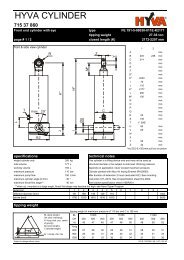
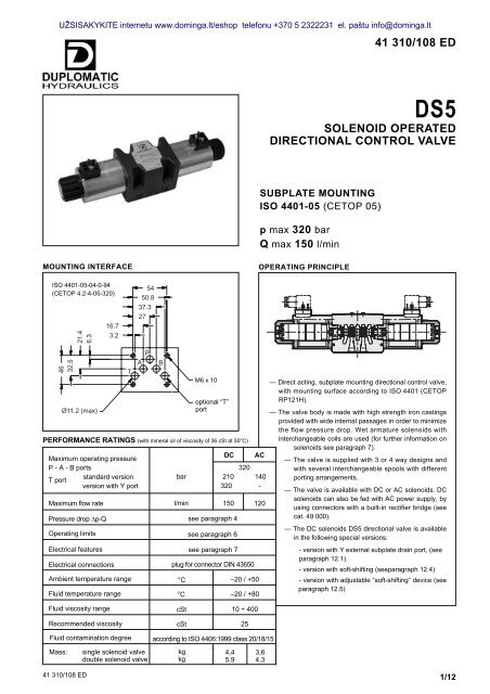
UŽSISAKYKITE internetu www.<strong>dominga</strong>.<strong>lt</strong>/eshop telefonu +370 5 2322231 el. paštu info@<strong>dominga</strong>.<strong>lt</strong>DS51 - IDENTIFICATION CODED S 5 - / 12 - K1 /Solenoidoperated directionalcontrol valveISO 4401-05(CETOP 05) sizeSpool type(see par. 3)S* TASA* TBSB* RKSeries:(the overall and mounting dimensionsremain unchanged from 10 to 19)Seals:N = NBR seals for mineral oil (standard)V = FPM seals for special fluidsDC power supplyD12 = 12 VD24 = 24 VD110 = 110 VD220 = 220 VD00 = valve without coils (see NOTE)AC power supplyManual override:omit for override integrated in the tube(standard)CM = manual override, boot protected(only for DC version)Coil electrical connection:plug for connector type DIN 43650 (standard)A24 = 24 V - 50 HzA48 = 48 V - 50 HzA110 = 110 V - 50 Hz / 120 V - 60 HzA230 = 230 V - 50 Hz / 240 V - 60 HzA00 = valve without coils (see NOTE)F110F220= 110 V - 60 Hz= 220 V - 60 HzNOTE: The locking rings of the coils and the relevant O-Rings are supplied together with valves2 - HYDRAULIC FLUIDSUse mineral oil-based hydraulic fluids HL or HM type, according to ISO 6743-4. For these fluids, use NBR seals (code N).For fluids HFDR type (phosphate esters) use FPM seals (code V).For the use of other fluid types such as HFA, HFB, HFC, please consu<strong>lt</strong> our technical department.Using fluids at temperatures higher than 80 °C causes a faster degradation of the fluid and of the seals characteristics.The fluid must be preserved in its physical and chemical characteristics.41 310/108 ED 2/12
UŽSISAKYKITE internetu www.<strong>dominga</strong>.<strong>lt</strong>/eshop telefonu +370 5 2322231 el. paštu info@<strong>dominga</strong>.<strong>lt</strong>DS53 - SPOOL TYPEType S*:2 solenoids - 3 positionswith spring centeringType SA*:1 solenoid side A2 positions (central + external)with spring centeringType SB*:1 solenoid side B2 positions (central + external)with spring centeringABABABaaP0TbbaaP0TP0TbbS1SA1SB1S2SA2SB2S3SA3SB3S4SA4SB4S5S6S7S8S9S10S11S12S17S18S19S20S21Type TA:1 solenoid side A2 external positionswith return springTAaaAPbBTType TB:1 solenoid side B2 external positionswith return springTBAPaBTbbS22TA02TB02S23TA23TB23Type RK:2 solenoids - 2 positionswith mechanical retentionABaaPbTbRKRK02RK11RKBesides the diagrams shown, which are the most frequently used, other special versions are available: consu<strong>lt</strong> our technical departmentfor their identification, feasibility and operating limits.41 310/108 ED 3/12
UŽSISAKYKITE internetu www.<strong>dominga</strong>.<strong>lt</strong>/eshop telefonu +370 5 2322231 el. paštu info@<strong>dominga</strong>.<strong>lt</strong>DS56 - OPERATING LIMITSThe curves define the flow rate operating fields according to the valve pressure of the different versions.The values have been obtained according to ISO 64003 norm with solenoids at rated temperature and supplied with vo<strong>lt</strong>age equal to 90% ofthe nominal vo<strong>lt</strong>age.The values have been obtained with mineral oil, viscosity 36 cSt, temperature 50 °C and fi<strong>lt</strong>ration according to ISO 4406:1999 class 18/16/13.p[bar]35030025020015010050025DC SOLENOID VALVE450 75 1001231255150Q [l/min]SPOOL TYPE CURVEP-A P-BS1,SA1,SB1 1 1S2, SA2, SB2 1 1S3, SA3, SB3 2 2S4, SA4, SB4 3 3S5 1 1S6 2 1S7 4 4S8 4 4S9 1 1S10 1 1S11 1 2S12 1 1SPOOL TYPE CURVEP-A P-BS17 1 3S18 1 1S19 3 1S20S21S22S23TA, TB 5 5TA02, TB02 3 3TA23, TB23 1 1RK 1 1RK02 1 1RK1, 1RK 1 1p[bar]3503002502001501005005253AC SOLENOID VALVE12 45 23 450 75 100 125150Q [l/min]SPOOL TYPE CURVEP-A P-BS1,SA1,SB1 1 1S2, SA2, SB2 2 2S3, SA3, SB3 2 2S4, SA4, SB4 4 4S5 1 1S6 2 1S7 3 3S8 3 3S9 2 2S10 1 1S11 1 2S12 1 1SPOOL TYPE CURVEP-A P-BS17 1 5S18 1 1S19 5 1S20S21S22S23TA, TB 1 1TA02, TB02 5 5TA23, TB23 1 1RK 1 1RK02 1 1RK1, 1RK 1 1NOTE: The values indicated in the graphs are relevant to the standard solenoid valve. The operating limits can be considerablyreduced if a 4-way valve is used with port A or B plugged.For flow and pressure performances of soft-shifting configuration (options F) see par. 12.5Flow and pressure performances of adjustable soft-shifting device configurations (options S) are influenced by the set shifting time.41 310/108 ED 5/12
UŽSISAKYKITE internetu www.<strong>dominga</strong>.<strong>lt</strong>/eshop telefonu +370 5 2322231 el. paštu info@<strong>dominga</strong>.<strong>lt</strong>DS57 - ELECTRICAL FEATURES7.1 SolenoidsThese are essentially made up of two parts: tube and coil. Thetube is threaded into the valve body and includes the armature thatmoves immersed in oil, without wear. The inner part, in contact withthe oil in the return line, ensures heat dissipation.The coil is fastened to the tube by a threaded ring, and can berotated, to suit the available space.NOTE 1: In order to further reduce the emissions, use of type Hconnectors is recommended. These prevent vo<strong>lt</strong>age peaks onopening of the coil supply electrical circuit (see CAT. 49 000).SUPPLY VOLTAGE FLUCTUATIONMAX SWITCH ON FREQUENCYDUTY CYCLEELECTROMAGNETIC COMPATIBILITY (EMC)emissions (see NOTE 1) EN 50081-1immunityEN 50082-2LOW VOLTAGECLASS OF PROTECTION:Atmospheric agents (CEI EN 60529)Coil insulation (VDE 0580)Impregnation± 10% Vnom15.000 ins/hr100%in compliance with89/336 EECin compliance with73/23/EEC96/68/EECIP 65 (see NOTE 2)class Hclass FNOTE 2: The IP65 protection degree is guaranteed only with the connectorcorrectly connected and installed.7.2 Current and absorbed power for DC solenoid valveThe table shows current and power consumption values relevant tothe different coil types for DC.The rectified current supply takes place by fitting the valve with ana<strong>lt</strong>ernating current source (50 or 60 Hz), rectified by means of abridge bui<strong>lt</strong>-in to the “D” type connectors (see cat. 49 000).7.3 Current and absorbed power for AC solenoid valveThe table shows current and power consumption values at inrushand at holding, relevant to the different coil types for AC current.Coils for direct current (values ± 5%)Suffix Nominal Resistance Current Power Coilvo<strong>lt</strong>age at 20°C consumpt. consumpt. code[V] [Ω] [A] [W]D12 12 3 - 3,4 3,81 45,8 1902870D24 24 12 - 14 1,90 45,3 1902871D110 110 235-270 0,44 48,4 1902872D220 220 960-1110 0,21 47,1 1902873NOTE: It is necessary to allow, when supplying the valve withrectified current, a reduction of the operating limits by 5-10%approx.Coils for a<strong>lt</strong>ernating current (values ± 5%)Suffix Nominal Frequency Resistance Current Current Power Power Coilvo<strong>lt</strong>age at 20°C consumption consumption consumption consumption codeat inrush at holding at inrush at holding[V] [Hz] [ohm] [A] [A] [VA] [VA]A24 24 0,53 25 3,96 600 95 190289050A48 482,09 12,5 2,3 600 110 1902891A110A230110V-50Hz 10,9 5,2 0,96 572 105120V-60Hz10,9 5,2 0,89 572 10550/60230V-50Hz 52,7 2,8 0,46 644 105240V-60Hz 52,7 2,8 0,38 644 10519028921902893F110 1108,80 5,2 0,95 572 105 190289460F220 220 35,2 2,7 0,48 594 105 19028958 - INSTALLATIONConfigurations with centering and return springs can be mounted in any position; type RK valves -without springs and with mechanical detent - must be mounted with the longitudinal axis horizontal.Valve fixing is by means of screws or tie rods, with the valve mounted on a lapped surface, with valuesof planarity and smoothness that are equal to or better than those indicated in the drawing. If theminimum values of planarity and/or smoothness are not met, fluid leakage between valve andmounting surface can easily occur.Surface finishing9 - ELECTRIC CONNECTORSThe solenoid valves are not supplied with connector. Connectors must be ordered separately.For the identification of the connector type to be ordered, please see catalogue 49 000.41 310/108 ED 6/12
UŽSISAKYKITE internetu www.<strong>dominga</strong>.<strong>lt</strong>/eshop telefonu +370 5 2322231 el. paštu info@<strong>dominga</strong>.<strong>lt</strong>DS510 - OVERALL AND MOUNTING DIMENSIONS FOR DC SOLENOID VALVESDS5 - S*DS5 - RKDS5 - SA*DS5 - TAdimensions in mm1 Mounting surface with sealing ringssolenoid position for SB* and TB configurations2 Standard manual override included in thesolenoid tube3 Coil (90° orientable)4 Coil removal space5 DIN 43650 electrical connector to beordered separately (see cat. 49 000)6 Connector removal space7 Manual override, boot protected CMSee par. 15 for fastening bo<strong>lt</strong>s and sealing rings41 310/108 ED 7/12
UŽSISAKYKITE internetu www.<strong>dominga</strong>.<strong>lt</strong>/eshop telefonu +370 5 2322231 el. paštu info@<strong>dominga</strong>.<strong>lt</strong>DS511 - OVERALL AND MOUNTING DIMENSIONS FOR AC SOLENOID VALVESDS5 - S*DS5 - RKDS5 - SA*DS5 - TAdimensions in mm1 Mounting surface with sealing rings2 Standard manual override included in thesolenoid position for SB* and TB configurationssolenoid tube3 Coil (360° orientable)4 Coil removal space5 DIN 43650 electrical connector to beordered separately (see cat. 49 000)6 Connector removal spaceSee par. 15 for fastening bo<strong>lt</strong>s and sealing rings41 310/108 ED 8/12
UŽSISAKYKITE internetu www.<strong>dominga</strong>.<strong>lt</strong>/eshop telefonu +370 5 2322231 el. paštu info@<strong>dominga</strong>.<strong>lt</strong>DS512 - SPECIAL VERSIONS FOR DC SOLENOID VALVE12.1 - Identification code for external drain versionD S 5 - / 12 - K1 / YSolenoidoperated directionalcontrol valveport for subplate external drain(see par. 12.2)ISO 4401-05(CETOP 05) sizeSpool type(see par. 3)Series n.:(the overall and mounting dimensions remainunchanged from 10 to 19)Seals:N = NBR seals for mineral oil (standard)V = FPM seals for special fluidsCoil electrical connection:plug for connector typeDIN 43650 (standard)Coil typeD12 = 12 VD24 = 24 VD110 = 110 VD220 = 220 V12.2 - Subplate external drain port (option Y)This version allows the operation with pressures up to 320 bar onthe valve T port.It is a drain port Y realized on the valve mounting interface incompliance with ISO 4401-05-05-0-94 (CETOP 4.2-4-R05). The Yport is connected with the solenoid chamber: in this way the tubesare not stressed by the pressure operating on the valve T port.21.4116.316.73.2625450.837.327ø 6.3 (max)4632.5TPABYattacco optional “T” "T"faco<strong>lt</strong>ativoportø 11.2 (max)M6x1041 310/108 ED 9/12
UŽSISAKYKITE internetu www.<strong>dominga</strong>.<strong>lt</strong>/eshop telefonu +370 5 2322231 el. paštu info@<strong>dominga</strong>.<strong>lt</strong>DS512.2 - Identification codefor soft-shifting versionsD S 5 - / - K1 /Solenoidoperated directionalcontrol valveISO 4401-05(CETOP 05) sizeSpool type (see par. 3)S1 S4F (for F version) TAS2 S4 (for S version) TBS9 S7 TA02S12 S8 TB02Series n.:12 - for version S13 - for version F(the overall and mounting dimensions remainunchanged from 10 to 19)12.4 - Fixed restrictor for soft-shifting (option F)This version enables hydraulic actuators to perform a smooth startand stop by reducing the speed of movement of the valve spool.The diagram on the side shows the operating limits of the spoolsavailable in the soft-shifting version (NOTE: for this version, the S9spool must be used instead of the S3 one).The table on the side shows the switching times. The valuesindicated are obtained according to ISO 6403 standard, withmineral oil viscosity 36 cSt at 50°C.The shifting time and characteristics curves, are influenced by theviscosity (and thus by the temperature) of the operating fluid.Moreover, times can vary according to the flow rate and operatingpressure values of the valve.SPOOL TYPE CURVE TIMESp[bar]35030025020015010050Coil electrical connection: plug for connectortype DIN 43650 (standard)Power supplyD12 = 12 VD24 = 24 VD110 = 110 VD220 = 220 VSeals:N = NBR seals for mineral oil (standard)V = FPM seals for special fluids3Options:F = soft-shifting (see par. 12.4)S = adjustable soft-shifting device(see par 12.5)0 25 50 75 100 125 1502231Q [l/min]P-A P-B ENERGIZING DE-ENERGIZINGS1, S12 1 1 300 ÷ 500 300 ÷ 500S2 2 2 450 200 ÷ 300S4F, S7, S8 3 3 400 400 ÷ 200S9 1 1 300 ÷ 500 300 ÷ 500TA, TB 2 2 300 ÷ 400 300 ÷ 400TA02, TB02 2 2 400 200 ÷ 3002 112.5 - Directional solenoid valve with adjustable“soft-shifting” device (option S)This solenoid valve is supplied with a suitable device, adjustable bythe user, which enables the control of the valve spool shifting time.In this way the hydraulic actuators can perform smooth movements,by controlling the valve switching time according to the machinecycle and the inertia of the moving parts.NOTE: during the first start-up the valve body must be filled with theoperating fluid through the tap (1) .1 Plug spanner 17 mm - tightening torque 20 Nm2 Shifting time adjustment screw countersunk hexspanner 2,5 mm41 310/108 ED 10/12
UŽSISAKYKITE internetu www.<strong>dominga</strong>.<strong>lt</strong>/eshop telefonu +370 5 2322231 el. paštu info@<strong>dominga</strong>.<strong>lt</strong>DS513 - SPARE PARTS FOR DC SOLENOID VALVEDC COILS IDENTIFICATION CODESupply vo<strong>lt</strong>ageD12 = 12 VD24 = 24 VD110 = 110 VD220 = 220 VC 31 - K1 / 20Series no.:(the overall and mountingdimensions remainunchanged from 20 to 29)plug for connector typeDIN 43650 (standard)1 Coil locking ring with seal included cod. 01193832 ORM type 0320 - 25 (32x2.5) - 70 Shore3 Coil (see identification code)4 Solenoid tubeTD31-M27/20N (NBR seals)TD31-M27/20V (FPM seals)NOTE: the solenoid tube is supplied with OR n° 5.5 OR type 3-912 (23.47x2.95) - 70 Shore6 N. 5 OR type 2050 (12.42x1.78) - 90 Shore7 For version with external subplate drain only(option Y):OR type 2037 (9.25x1.78) - 90 ShoreSEALS KITThe codes here below include O-Rings ref. 2, 5, 6 and 7.Cod. 1984418 NBR sealsCod. 1984419 FPM (viton) seals41 310/108 ED 11/12
UŽSISAKYKITE internetu www.<strong>dominga</strong>.<strong>lt</strong>/eshop telefonu +370 5 2322231 el. paštu info@<strong>dominga</strong>.<strong>lt</strong>DS514 - SPARE PARTS FOR AC SOLENOID VALVEAC COILS IDENTIFICATION CODEC 25.4 - K1 / 11Supply vo<strong>lt</strong>ageA24 =24 V - 50 HzA48 =48 V - 50 HzA110 = 110 V - 50 Hz120 V - 60 HzA230 = 230 V - 50 Hz240 V - 60 HzF110 =110 V - 60 HzF220 = 220 V - 60 HzSEALS KITSeries no.:(the overall andmounting dimensionsremain unchangedfrom 10 to 19)plug for connector typeDIN 43650 (standard)The codes here below include O-Rings ref. 2, 4, 6 and 7.Cod. 1984420 NBR sealsCod. 1984421 FPM (viton) seals1 Coil locking ring cod. 01194022 OR type 4100 (24.99x3.53)- 90 Shore3 Coil (see identification code)4 OR type2112 (2.9x1.78) - 90 Shore5 Solenoid tubes:TA25.4-M27/11N (NBR seals)TA25.4-M27/11V (FPM seals)NOTE: the tube is supplied with OR n° 6.6 OR type 3-912 (23.47x2.95) - 70 Shore7 N. 5 OR type 2050 (12.42x1.78) - 90 Shore15 - FASTENING BOLTS4 bo<strong>lt</strong>s M6x40 (class 12.9 recommended)Tightening torque 8 Nm16 - SUBPLATES (See catalogue 51 000)Type PMD4-AI4G with rear ports 1/2” BSPType PMD4-AL4G with side ports 1/2” BSPDUPLOMATIC OLEODINAMICA SpA20025 LEGNANO (MI) - P.le Bozzi, 1 / Via EdisonTel. 0331/472111 - Fax 0331/54832841 310/108 ED REPRODUCTION IS FORBIDDEN. THE COMPANY RESERVES THE RIGHT TO APPLY ANY MODIFICATIONS.12/12