DFP-1010 RS-232 DF Bearing Processor User ... - RDF Products
DFP-1010 RS-232 DF Bearing Processor User ... - RDF Products
DFP-1010 RS-232 DF Bearing Processor User ... - RDF Products
Create successful ePaper yourself
Turn your PDF publications into a flip-book with our unique Google optimized e-Paper software.
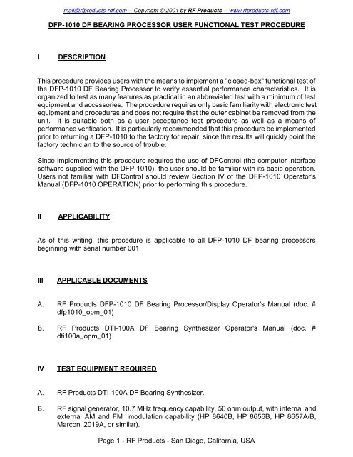
mail@rfproducts-rdf.com -- Copyright © 2001 by RF <strong>Products</strong> -- www.rfproducts-rdf.com<strong><strong>DF</strong>P</strong>-<strong>1010</strong> <strong>DF</strong> BEARING PROCESSOR USER FUNCTIONAL TEST PROCEDUREIDESCRIPTIONThis procedure provides users with the means to implement a "closed-box" functional test ofthe <strong><strong>DF</strong>P</strong>-<strong>1010</strong> <strong>DF</strong> <strong>Bearing</strong> <strong>Processor</strong> to verify essential performance characteristics. It isorganized to test as many features as practical in an abbreviated test with a minimum of testequipment and accessories. The procedure requires only basic familiarity with electronic testequipment and procedures and does not require that the outer cabinet be removed from theunit. It is suitable both as a user acceptance test procedure as well as a means ofperformance verification. It is particularly recommended that this procedure be implementedprior to returning a <strong><strong>DF</strong>P</strong>-<strong>1010</strong> to the factory for repair, since the results will quickly point thefactory technician to the source of trouble.Since implementing this procedure requires the use of <strong>DF</strong>Control (the computer interfacesoftware supplied with the <strong><strong>DF</strong>P</strong>-<strong>1010</strong>), the user should be familiar with its basic operation.<strong>User</strong>s not familiar with <strong>DF</strong>Control should review Section IV of the <strong><strong>DF</strong>P</strong>-<strong>1010</strong> Operator’sManual (<strong><strong>DF</strong>P</strong>-<strong>1010</strong> OPERATION) prior to performing this procedure.IIAPPLICABILITYAs of this writing, this procedure is applicable to all <strong><strong>DF</strong>P</strong>-<strong>1010</strong> <strong>DF</strong> bearing processorsbeginning with serial number 001.IIIAPPLICABLE DOCUMENTSA. RF <strong>Products</strong> <strong><strong>DF</strong>P</strong>-<strong>1010</strong> <strong>DF</strong> <strong>Bearing</strong> <strong>Processor</strong>/Display Operator's Manual (doc. #dfp<strong>1010</strong>_opm_01)B. RF <strong>Products</strong> DTI-100A <strong>DF</strong> <strong>Bearing</strong> Synthesizer Operator's Manual (doc. #dti100a_opm_01)IVTEST EQUIPMENT REQUIREDA. RF <strong>Products</strong> DTI-100A <strong>DF</strong> <strong>Bearing</strong> Synthesizer.B. RF signal generator, 10.7 MHz frequency capability, 50 ohm output, with internal andexternal AM and FM modulation capability (HP 8640B, HP 8656B, HP 8657A/B,Marconi 2019A, or similar).Page 1 - RF <strong>Products</strong> - San Diego, California, USA
mail@rfproducts-rdf.com -- Copyright © 2001 by RF <strong>Products</strong> -- www.rfproducts-rdf.comC. Regulated DC power supply, +13.8 VDC nominal output with 1 ampere minimumoutput current capacity (Astron <strong>RS</strong>-7A or similar).D. Multi-meter, w/DC current measurement ability up to 1 ampere (Micronta 22-185A orsimilar).E. Windows 95/98/NT4 personal computer (120 MHz or faster) with uncommitted serialport and <strong>DF</strong>Control user software (supplied on the RF <strong>Products</strong> Publications CDincluded with the <strong><strong>DF</strong>P</strong>-<strong>1010</strong> Operator’s Manual). <strong>DF</strong>Control must be Version 1.2 orhigher.F. Audio monitor with speaker output and volume control.G. Miscellaneous plugs, cables, and adaptors as required.H. (Optional.) Oscilloscope (Tektronix 465 or similar).I. (Optional.) Frequency counter, 100-1000 Hz capability (Leader LDC-825 or similar).VTEST PROCEDUREA. PHYSICAL INSPECTION, MECHANICAL ALIGNMENT, & PRELIMINARY STEPS1__2__3__4__5__With the <strong><strong>DF</strong>P</strong>-<strong>1010</strong> disconnected from its power source, carefully inspect the unit forany signs of physical damage.Remove the fuse from the fuse-holder (located near the upper right corner of the frontpanel)and inspect it to verify that it is a GMA-type 5 mm x 20 mm 2.5 ampere fast-blowfuse. If not, replace it with the correct type. Otherwise, reinstall it in the fuse-holder.Remove the front-panel configuration setup cover plate (by first loosening the fourcaptive thumbscrews) to expose the spare fuse and the configuration setup switches.(Optional.) Verify that the spare fuse is present (it is located immediately above thedip-switches and to the immediate left of the DELAY COMP switch). Carefully removeit from its two retaining clamps (by carefully prying from the left with a flat-bladescrewdriver) and inspect it to verify that it is a GMA-type 5 mm x 20 mm 2.5 amperefast-blow fuse (i.e., the same type as that was verified in step V-A-2 above). Also verifythat this fuse is good, preferably using an ohmmeter. If an ohmmeter is unavailable,rely instead on visual inspection. Once verified, carefully reinstall the spare fuse in itsretaining clamps.Some of the configuration setup switches will likely need to be changed from theircurrent settings as part of this procedure. To facilitate returning these switches to theircurrent settings at the completion of this procedure, record these settings in the spacesprovided below:Page 2 - RF <strong>Products</strong> - San Diego, California, USA
mail@rfproducts-rdf.com -- Copyright © 2001 by RF <strong>Products</strong> -- www.rfproducts-rdf.comIF SELECT_____________DELAY COMP__________DIP-SWITCH #8__________DIP-SWITCH #9__________Note that the remaining dip-switch sections (1-7 and 10) are non-functional).6__Set the configuration setup switches as follows:IF SELECT - 10.7DELAY COMP - 0DIP-SWITCH #8 - IF (down)DIP-SWITCH #9 - NORM (down)Verify that the remaining dip-switch sections (1-7 and 10) are down.B. POWER-UP TEST1__2__3__4__Set the DC POWER switch to OFF and then connect the <strong><strong>DF</strong>P</strong>-<strong>1010</strong> to the +13.8 VDCregulated power source.Power-up the <strong><strong>DF</strong>P</strong>-<strong>1010</strong> by setting the DC POWER switch to ON and verify that thepower indicator lamp (part of the DC POWER rocker switch) illuminates.Verify with the multi-meter that the current drawn by the <strong><strong>DF</strong>P</strong>-<strong>1010</strong> from the +13.8 VDCsupply is approximately 450 milliamperes. Be sure nothing is connected to theANTENNA CONTROL, 11-16 VDC power output, or REMOTE connectors whileconducting this measurement.Remove the power cable from the lower 11-16 VDC power connector and connect itinstead to the upper 11-16 VDC power connector (after first removing its tetheredprotective cap). Verify that the unit still powers-up.C. COMPUTER INTERFACE TEST1__2__3__4__5__7__Set the DC POWER switch to OFF.Connect the computer interface cable between the <strong><strong>DF</strong>P</strong>-<strong>1010</strong> REMOTE connector andthe host computer serial port.Install the supplied user software <strong>DF</strong>Control (V1.2 or higher) and its associated filesin the host computer as discussed in Section IV-C-2 of the Operator’s Manual(“Installing <strong>DF</strong>Control”).Set the DC POWER switch back to ON.Confirm that dip-switch #8 is still set to IF (down) and verify that the audio cable (andany attached adaptor) has been removed from the <strong><strong>DF</strong>P</strong>-<strong>1010</strong> AM AUDIO IN jack.Start <strong>DF</strong>Control and verify that it is able to “handshake” with the <strong><strong>DF</strong>P</strong>-<strong>1010</strong> as indicatedby the appearance a green status light on the main user screen. See <strong><strong>DF</strong>P</strong>-<strong>1010</strong>Operator’s Manual Section IV-C-3 (“Starting And Exiting <strong>DF</strong>Control”). If <strong>DF</strong>Control willPage 3 - RF <strong>Products</strong> - San Diego, California, USA
mail@rfproducts-rdf.com -- Copyright © 2001 by RF <strong>Products</strong> -- www.rfproducts-rdf.comnot start, follow the troubleshooting steps discussed in that Section.D. LISTEN-THROUGH TESTS1__2__3__4__5__6__7__8__9__Restore all of <strong>DF</strong>Control’s Operating Modes to their default attributes. To do this, firstclick Configure and then Operating Modes. Once done, click the Restore toDefaults bar for the current Mode to Edit (represented by a number from 1 to 10).Next, repeat this process for the remaining 9 Modes to Edit so that all 10 OperatingModes are reset to their default attributes.Connect the audio monitor to the LINE AUDIO OUT phono jack.Set the Operating Mode is to FM Voice, verify that the IF Bandwidth is set to Wide,and set the Audio Output to Enabled.A hissing sound should be audible from the audio monitor. Adjust its volume controlas required for a comfortable listening level.Verify that the hissing sound can be muted by setting the Audio Output to Disabled.Once verified, reset to Enabled.Without changing the setting of the audio monitor volume control, change theOperating Mode to AM Voice and verify that the hissing sound greatly diminishes involume as compared to FM Voice. Verify that the IF Bandwidth is still set to Wide.Increase the audio monitor volume control as required so that the hissing sound isagain plainly audible.Set the Operating Mode to SSB Voice and verify that the hissing sound is similar involume as compared to AM Voice, but lower in pitch. Also verify that this causes theIF Bandwidth to change to Narrow.With the Operating Mode still in SSB Voice, change the IF Bandwidth to Wide andverify that the hissing sound becomes higher in pitch as a result.10__ Return the Operating Mode to FM Voice, set up the signal generator for a 10.700MHz -60 dBm CW output and connect the signal generator RF output to the <strong><strong>DF</strong>P</strong>-<strong>1010</strong>IF IN jack through a short length of 50 ohm coaxial cable.11__ Verify that the application of the 10.700 MHz CW signal to the <strong><strong>DF</strong>P</strong>-<strong>1010</strong> fully quietsthe FM hissing sound and results in an approximately half-scale meter indication. (Besure that the Meter Type is set to Signal Strength.)12__ Set the signal generator for 3 kHz deviation internal FM at a 1 kHz modulation rate.A clean-sounding 1 kHz tone should be plainly audible. Adjust the audio monitorvolume control as required for a comfortable listening level.13__ Verify that the Signal Strength Meter is still at approximately half-scale.Page 4 - RF <strong>Products</strong> - San Diego, California, USA
mail@rfproducts-rdf.com -- Copyright © 2001 by RF <strong>Products</strong> -- www.rfproducts-rdf.com14__ (Optional.) Disconnect the audio monitor and connect the oscilloscope to the LINEAUDIO OUT jack using an appropriate interface cable. Verify that a reasonablyundistorted 1 kHz sine wave is visible on the oscilloscope with a typical amplitude of0.3 volts peak-to-peak. Note that the actual amplitude may vary considerably.15__ Disconnect the oscilloscope and reconnect the audio monitor to the LINE AUDIO OUTjack.16__ Set the Operating Mode to AM Voice and reconfigure the signal generator for 50%internal AM at a 1 kHz modulation rate (be sure to disable signal generator FM) at thesame -60 dBm output level. A clean-sounding 1 kHz tone should again be plainlyaudible. Adjust the audio monitor volume control as required for a comfortable listeninglevel.17__ Verify that the Signal Strength Meter is still at approximately half-scale.18__ (Optional.) Disconnect the audio monitor and connect the oscilloscope to the LINEAUDIO OUT jack using an appropriate interface cable. Verify that a reasonablyundistorted 1 kHz sine wave is visible on the oscilloscope with a typical amplitude of0.5 volts peak-to-peak. Note that the actual amplitude may vary considerably.19__ Disconnect the oscilloscope and reconnect the audio monitor to the LINE AUDIO OUTjack.20__ Set the Operating Mode to SSB Voice and reconfigure the signal generator for a -60dBm CW (unmodulated) output at 10.701 MHz. A clean-sounding tone near 1 kHzshould again be plainly audible. If a tone near 1 kHz is not heard, change the signalgenerator frequency slightly as required. Adjust the audio monitor volume control asrequired for a comfortable listening level.21__ Verify that the Signal Strength Meter is still at approximately half-scale.22__ (Optional.) Disconnect the audio monitor and connect the oscilloscope to the LINEAUDIO OUT jack using an appropriate interface cable. Verify that a reasonablyundistorted 1 kHz sine wave is visible on the oscilloscope with a typical amplitude of0.6 volts peak-to-peak and then disconnect the oscilloscope. Note that the actualamplitude may vary considerably.23__ Restore the signal generator frequency to 10.700 MHz.24__ Change the Meter Type command field to Center Tune and verify that the meterindicates zero (plus or minus half a division) on the tuning scale.25__ Increment the signal generator frequency upward in 1 kHz steps, stopping at 10.704MHz and verify that the meter correctly tracks this change (the tuning scale iscalibrated in steps of approximately 1 kHz). In a similar fashion, verify that the tuningmeter again correctly tracks the frequency change when the signal generator frequencyis incremented downward in 1 kHz steps, stopping at 10.696 MHz.26__ Return the signal generator frequency to 10.700 MHz, change the Meter Type toPage 5 - RF <strong>Products</strong> - San Diego, California, USA
mail@rfproducts-rdf.com -- Copyright © 2001 by RF <strong>Products</strong> -- www.rfproducts-rdf.comSignal Strength, disconnect the audio monitor, and leave the test setup intact for thetests that follow.E. BEARING DISPLAY TESTS1__2__3__4__5__6__7__8__9__Verify that the signal generator is still set for a 10.700 MHz -60 dBm CW output andconfirm that nothing is plugged into the AM AUDIO IN jack.Set the Operating Mode to FM Voice and verify that the IF Bandwidth is set to Wide.Set the Video Gain to Low Gain and verify that the Track & Hold is set to Off,Antenna Orientation to Ground, <strong>Bearing</strong> Offset and Averaging Time both to 0.0,and <strong>DF</strong> operation not disabled.Configure the bearing display for 0.2° resolution. To do this, first click Configure, thenDisplay Options, then 0.2.Connect the DTI-100A <strong>DF</strong> <strong>Bearing</strong> Synthesizer to the signal generator and <strong><strong>DF</strong>P</strong>-<strong>1010</strong>(refer to the DTI-100A Operator's Manual as required for details regarding this testsetup). Set the DTI-100A AZIMUTH selector to 0° and the signal generator for 30%external AM (note that the DTI-100A GAIN control must be appropriately set incoordination with any relevant signal generator modulation gain controls to establishthe required 30% modulation level).A 0° bearing should now be visible with a full-length analog bearing display bearingvector, and a numeric bearing display indication of 0° (+/- 1.0°).Verify that the center dot in the analog bearing display is yellow (as opposed to red).Rotate the DTI-100A AZIMUTH selector in succession to the remaining 11 azimuthsand confirm that the correct bearings are indicated on both the analog and numericbearing displays. All azimuths should be correct to within 1.0°.Set the DTI-100A AZIMUTH selector back to 0°. With the Operating Mode still set toFM Voice, rotate the DTI-100A AZIMUTH selector to 315°. The analog bearing displayvector should correspondingly move from 0° to 315° in approximately 2 seconds.10__ Change the Operating Mode to CW Beacon and wait a moment for the display tosettle. Rotate the DTI-100A AZIMUTH selector from 315° back to 0°. The analogbearing display vector should correspondingly move from 315° to 0° in just under onesecond.11__ Change the Operating Mode to A.I.D. Beacon and wait a moment for the display tosettle. Rotate the DTI-100A AZIMUTH selector from 0° to 315°. The analog bearingdisplay vector should correspondingly move from 0° to 315° in approximately half asecond.12__ Set the Operating Mode back to FM Voice and the Video Gain to High Gain.Page 6 - RF <strong>Products</strong> - San Diego, California, USA
mail@rfproducts-rdf.com -- Copyright © 2001 by RF <strong>Products</strong> -- www.rfproducts-rdf.com13__ Rotate the DTI-100A AZIMUTH selector back to 0°, set the signal generator externalAM modulation percentage to 0% and then slowly increase it while observing the yellowcenter dot in the analog bearing display. Verify that the dot changes from yellow to redwhen the modulation percentage reaches 15% or so and note this percentage.14__ Slowly decrease the signal generator external AM modulation percentage whileobserving the red dot. Verify that the dot changes from red back to yellow when themodulation percentage reaches a level approximately three percentage points lessthan that observed in the previous step.15__ Note that the analog bearing display has three concentric rings (two closely spacedouter rings containing the azimuth calibration marks and a much smaller gray inner ringcloser to the center dot). The two outer rings change from green to yellow when thebearing vector reaches (or begins to exceed) full-scale. Verify that these two outerrings are yellow.16__ Set the Operating Mode to CW Beacon.17__ Reset the signal generator external AM modulation percentage to 30% and then rotatethe DTI-100A GAIN control slowly counter-clockwise (to reduce modulation) until thebearing vector length is approximately half-scale. Verify that the two yellow outer ringschange to green as a result.18__ Carefully rotate the DTI-100A GAIN control clockwise until the two outer rings justchange from green to yellow. If this step seems “tricky” and difficult to implementprecisely, try first reducing the signal generator external AM modulation percentage.19__ Change the Video Gain from High Gain to Low Gain. The bearing vector shoulddiminish in length to 25% of what it was when the Video Gain was set to High Gain,and should now be very close in length to the radius of the gray inner ring.20__ Set the Track & Hold to T&H On, the Operating Mode to FM Voice, and restore thesignal generator external AM modulation percentage to 30% (appropriately resettingthe DTI-100A GAIN control as required).21__ Disconnect the coaxial cable from the signal generator to interrupt the signal input tothe <strong><strong>DF</strong>P</strong>-<strong>1010</strong>. The 0° analog display vector should remain “frozen” for approximately2.5 seconds before it disappears. Note 1: Since the signal must be interruptedsuddenly for the Track & Hold to function properly, the coaxial cable should bedisconnected rapidly. If the signal generator has a carrier on/off switch, this may alsobe used, but it is important that the activation of such a switch result in completedisabling of the signal generator RF output (with some signal generators, theseswitches only partially disable the RF output). Note 2: Some <strong><strong>DF</strong>P</strong>-<strong>1010</strong>'s may becustomized for hold times other than 2.5 seconds.22__ Change the DTI-100A AZIMUTH selector from 0° to 90°, restore the signal generatoroutput to the <strong><strong>DF</strong>P</strong>-<strong>1010</strong>, and repeat the previous step.23__ Repeat the previous step for a DTI-100A AZIMUTH selection of 45°. Observe thebearing carefully to verify that it does not drift during the 2.5 second “hold” period.Page 7 - RF <strong>Products</strong> - San Diego, California, USA
mail@rfproducts-rdf.com -- Copyright © 2001 by RF <strong>Products</strong> -- www.rfproducts-rdf.com24__ Again restore the signal generator output and set the Track & Hold to T&H Off.25__ Set dip-switch #9 to RECP (up). The bearing should change from 45° to 225° as aresult. Return dip-switch #9 to NORM (down).26__ Rotate the DTI-100A AZIMUTH selector to 0° and set the Video Gain to High Gainand the Operating Mode to CW Beacon.27__ Increase the signal generator external AM modulation percentage to 50% and set theRF output level to -130 dBm.28__ Verify that a 0° bearing vector is present with a length approximately 30-50% fullscreen.Although bearing jitter will be present, the bearing should nonetheless berecognizable as being approximately 0° (to verify this, rotate the DTI-100A AZIMUTHselector back and forth between 0° and 22.5° - the resulting azimuth change should beclearly discernable. This step confirms <strong>DF</strong> sensitivity.29__ Disconnect the DTI-100A from the <strong><strong>DF</strong>P</strong>-<strong>1010</strong>.F. AGC TESTS (Optional)1__2__3__5__6__Set up the signal generator for a 10.7 MHz -20 dBm CW output.Verify that the Meter Type command field is still set to Signal Strength and reduce theoutput level of the signal generator as required for an Signal Strength meter readingof just slightly less than full-scale (but not greater than -20 dBm.)Set the Operating Mode to CW Slow, wait a moment or two for the change to takeeffect, then disable the signal generator RF output (do this either via the signalgenerator carrier on/off switch or by rapidly disconnecting the coaxial cable). TheSignal Strength meter indication should fall to 1.5 (i.e, 15% full-scale) in approximately2 seconds. Repeat this step as many times as necessary for confirmation, but oncecompleted, leave the signal generator RF output disabled before proceeding to thenext step.Set the Operating Mode to A.I.D. Beacon, wait a moment or two for the change totake effect, restore the signal generator RF output, then again disable the signalgenerator RF output. The Signal Strength meter indication should fall to 1.5 inapproximately (typically just under) 1 second. Even though it may be difficult toprecisely gauge the amount of time required for the Signal Strength meter indicationto fall, it should fall noticeably faster than in the previous step. If necessary, repeatboth the previous step and this step for comparison as many times as required forconfirmation, but be sure to leave the signal generator RF output disabled prior tochanging the Operating Mode.Set the Operating Mode to CW Fast, wait a moment or two for the change to takeeffect, restore the signal generator RF output, then again disable the signal generatorRF output. The Signal Strength meter indication should fall to 1.5 in approximately(typically just under) 0.5 second. Even though it may be difficult to precisely gauge thePage 8 - RF <strong>Products</strong> - San Diego, California, USA
mail@rfproducts-rdf.com -- Copyright © 2001 by RF <strong>Products</strong> -- www.rfproducts-rdf.comamount of time required for the Signal Strength meter indication to fall, it should fallnoticeably faster than in the previous step. If necessary, repeat both the previous stepand this step for comparison as many times as required for confirmation, but be sureto leave the signal generator RF output disabled prior to changing the OperatingMode.G. ANTENNA BANDSWITCHING TESTS1__ Set the <strong>DF</strong> Antenna Model to Generic and the <strong>DF</strong> Antenna Band to Band #2.2__Using a voltmeter or oscilloscope, probe pins 3, 4, and 7 of the ANTENNA CONTROLconnector to verify the correct logic states . Refer to <strong><strong>DF</strong>P</strong>-<strong>1010</strong> Operator’s ManualAppendix D (<strong><strong>DF</strong>P</strong>-<strong>1010</strong> FRONT-PANEL MULTI-PIN CONNECTOR PIN-OUTS) for thepin-out of this connector. Also refer to the <strong>DF</strong> ANTENNA BAND 3-BIT LOGIC CODEStable in Appendix I (<strong>DF</strong> ANTENNA FREQUENCY COVERAGE INFORMATION) of thissame manual for the correct logic states and their corresponding voltage levels.*CAUTION*Be careful not to short adjacent pins to each other or to the connector shell while conductingthis measurement.3__ Repeat the above step for <strong>DF</strong> Antenna Bands 3-9.H. TONE TESTS1__2__3__Set the <strong>DF</strong>Control Operating Mode to FM Voice and confirm that <strong>DF</strong> operation isenabled.Probe pin 1 of the <strong><strong>DF</strong>P</strong>-<strong>1010</strong> rear-panel ANTENNA CONTROL connector with theo'scope and verify the presence of a 1.0 VPP clean sine wave (the X-axis tone). Usinga frequency counter, verify that the tone frequency is 133 Hz (for standard units). Becareful not to short-circuit adjacent pins in this and the following steps.In a similar fashion, probe pin 2 of the ANTENNA CONTROL connector and verify thepresence of a 1.0 VPP clean sine wave (the Y-axis tone). Using a frequency counter,verify that the tone frequency is 160 Hz (for standard units). Pin 2 is immediatelycounter-clockwise from pin 1.4__ Set the Operating Mode to A.I.D. Beacon and repeat the previous two steps. The X-and Y-axis tone frequencies should now be 533 Hz and 640 Hz, respectively (and still1.0 VPP clean sine waves).5__Set the Operating Mode to Spare 2, click Configure, click Operating Modes, thenselect Medium Tones. The X- and Y-axis tone frequencies should now be 267 Hz and320 Hz, respectively (and still 1.0 VPP clean sine waves).Page 9 - RF <strong>Products</strong> - San Diego, California, USA
mail@rfproducts-rdf.com -- Copyright © 2001 by RF <strong>Products</strong> -- www.rfproducts-rdf.comI. FINAL STEPS__Disconnect all test equipment and restore the <strong><strong>DF</strong>P</strong>-<strong>1010</strong> front-panel configurationsetup switches to their original positions (recorded in step V-A-5). If it is believed thatsome of these original switch settings are in error, resolve this matter first. Once theseswitches have been properly set, re-install the front-panel configuration setup coverplate using the four captive thumbscrews. Re-install the tethered protective cap to theupper 11-16 VDC power connector if this has not already been done.VIRETURNING EQUIPMENT TO FACTORY FOR REPAIRWhen returning equipment to the factory for repair, it is very important that the equipment beaccompanied by a detailed report listing all symptoms, along with any background informationregarding the circumstances that may have led to the failure. If a problem occursintermittently or only in specific modes of operation, this should be noted as well. If the aboveuser functional test procedure has been performed, the specific test(s) the unit failed shouldbe listed. Before returning any equipment, please contact RF <strong>Products</strong> at (619) 583-2024/2140 (Tel/Fax) or via e-mail at mail@rfproducts-rdf.com to obtain return authorization.Rev C01/09-01/dfp<strong>1010</strong>_tpu_01Copyright © 2001 by RF <strong>Products</strong>Original Writing: May, 1998Page 10 - RF <strong>Products</strong> - San Diego, California, USA


