Download - saf-holland
Download - saf-holland
Download - saf-holland

Create successful ePaper yourself
Turn your PDF publications into a flip-book with our unique Google optimized e-Paper software.
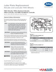
ContentsContentsPageIntroduction ............................................. 2Warranty .................................................. 2Notes, Cautions, and Warnings ................. 2Section 1 – General Safety Instructions .....3Components Exploded View ......................4Components Parts List ..............................5Dimensions ...............................................5Section 2 – Drawbar Eye Dimensions........ 6ContentsPageSection 3 – Load Ratings per SAE J847 ..... 6Section 4 – Towing Applications ............... 6Section 5 – General Information ............... 6Section 6 – General Safety Information .... 6Section 7 – Mounting Instructions ....... 7-15Section 8 – Operating Instructions ......... 16Section 9 – Maintenance ....................17-18Section 10 – Replacement Kits ................19IntroductionThis manual provides information necessaryfor the proper operation, maintenance, andinspection of the SAF HOLLAND pintle hook.NOTE: For Holland replacementcomponents contactSAF-HOLLAND CustomerService: 1-888-396-6501.WarrantyRefer to the complete warranty for thecountry in which the product will beused. A copy of the written warranty canbe downloaded from our SAF-HOLLANDwebsite (www.<strong>saf</strong><strong>holland</strong>.us).Notes, Cautions, and WarningsYou must read and understand all of theprocedures presented in this manual beforestarting any work on the pintle hook.NOTE: In the United States, work shop<strong>saf</strong>ety requirements are defined byfederal and/or state OccupationalSafety and Health Act. Equivalentlaws may exist in other countries.This manual is written basedon the assumption that OSHAor other applicable employee<strong>saf</strong>ety regulations are followedby the location where workis performed.Proper tools must be used to performthe maintenance and repair proceduresdescribed in this manual.Throughout this manual, you will notice theterms “NOTE”, “IMPORTANT”, “CAUTION”, and“WARNING” followed by important productinformation. So that you may better understandthe manual, those terms are as follows:NOTE: Includes additional informationto enable accurate and easyperformance of procedures.IMPORTANT: Includes additionalinformation that ifnot followed couldlead to hinderedproduct performance.Used without the <strong>saf</strong>etyalert symbol, indicatesa potentially hazardoussituation which, if notavoided, may result inproperty damage.Indicates a potentiallyhazardous situationwhich, if not avoided,may result in minor ormoderate injury.Indicates a potentiallyhazardous situation which,if not avoided, could resultin death or serious injury.2XL-PH10405UM-en-US Rev A · 2011-03-18 · Amendments and errors reserved. © SAF-HOLLAND, Inc.
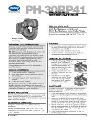
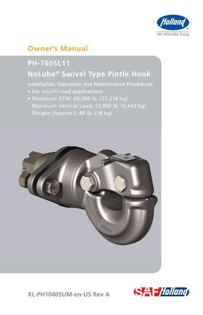
Dimensions, SAE & General Information2. Drawbar Eye Dimensions3" (76.2 mm) I.D with a 1.63" (41.3 mm)diameter cross section.3. Load Ratings Per SAE J847This product meets or exceeds the testingrequirements for SAE J847 Type II Loads.Maximum GTW: 60,000 lb. (27,216 kg)Maximum Vert. Load: 12,000 lb. (5,443 kg)4. Towing ApplicationsFor general over-the-road towing. UseONLY with a non-swivel type drawbar. Foroff-road applications, reduce the abovecapacities by 25%.IMPORTANT: Off-road refers to terrainon which a tractor-traileroperates which is unpavedand rough, or ungraded.Any terrain not consideredpart of the system ofpublic roads falls underthis heading.5. Other steps and inspections are alsorequired. Consult D.O.T. regulationsand American Trucking Associationfor complete coupling and uncouplingprocedures. These cover items such ascargo securement, brakes, lights, <strong>saf</strong>etychains, and other important requirements.6. General Safety InformationThis equipment must not be used in acareless manner.During Operation:1. Maintain adequate vertical (tongue)load to properly control the towed unit(generally 10% of maximum GTW) butdo not exceed the rated capacities.2. Do not damage the latch. Be particularlycareful during coupling and uncoupling.3. Wear <strong>saf</strong>ety goggles during installationand removal.4. Never strike any part of the item witha steel hammer.5. General Information1. Do not modify or add to the product.2. Do not weld on this product.3. This product is covered by SAF-Holland’sCommercial Warranty. SAF-Hollandreserves the right, without giving priornotice, to change specifications anddimensions as designs are alteredor improved.4. Inspect the coupling device on the towvehicle for proper operation. Do notuse any coupling device that does notoperate properly.6XL-PH10405UM-en-US Rev A · 2011-03-18 · Amendments and errors reserved. © SAF-HOLLAND, Inc.
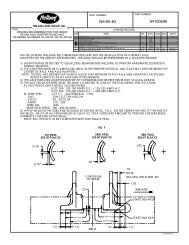
Mounting Instructions7. Mounting InstructionsNOTE: It is suggested that thisinstallation be performedwith two persons.1. Use a mounting structure of sufficientstrength to support the rated capacityof the pintle hook in accordance withSAE J849 and SAE J847 respectively.2. Check for either .75" (19.1 mm) or.375" (9.53 mm) mounting platethickness and follow appropriateinstructions according to the platethickness on the following pages.3. The bolt holes and mounting clearancearea are detailed in (Figure 1).4. This pintle hook system seals theflanges of the mounting structureusing square O-rings. The mountingstructure should be cleaned andprepared on the inboard and outboardmounting surfaces to properly acceptand function with O-ring seals.5. Ensure that all seals and felt washersare used, properly installed, and notdamaged during the install. If any of theseals or felt washers are damaged orlost during the install, refer to Section 10for replacement seal kit information.6. During disassembly retain all componentson a clean work surface to avoid anyscratching, denting, marring, or damageto the pintle hook shank coating,flange coating, and flange bushings.Figure 12.00"(50.8 mm)4.00"(101.6 mm)Figure 24.25"(108.0 mm)8.50"(215.9 mm)6.50"(165.1 mm) 2X Ø .78"(19.8 mm)Ø 1.88"(47.6 mm)NOTE: During disassembly the flangescan move and the seals maydislodge and need to bereseated by carefully pressingthem back into their correctgroove by hand prior to install.7. Begin disassembly by removing thetwo (2) 3/4" Grade 8 bolts (XB-772)and 3/4" lock nuts (XB-HNH-34-F)(Figure 2).XL-PH10405UM-en-US Rev A · 2011-03-18 · Amendments and errors reserved. © SAF-HOLLAND, Inc.7
Mounting Instructions8. Remove the cotter pin (XB-T-60),castellated nut (XB-771-1), washer(XA-768), and optional .375" spacer(XB-11472) (Figure 3).9. For .75" (19.1 mm) plate mountdiscard the .375" (9.53 mm) spacer(XB-11472). For .375" (9.53 mm) platemount retain the .375" (9.53 mm)spacer (XB-11472).10. Carefully remove the front flangeassembly (XA-11467) from the pintlehook paying attention not to damagethe front felt washer (XB-11471),U-cup seal (XB-11470), or squareO-ring seals (XB-11465) (Figure 4).11. Remove and discard the single largediameter assembly shipping spacer(XB-11466). Do not remove the rearflange square O-ring (XB-11465) orrear flange assembly (XA-11462)(Figure 5).12. Ensure the square O-rings (XB-11465)are seated in the front mounting flangeand rear mounting flange correctly.NOTE: For mounting to .75" (19.1 mm)plate, see steps 13a-24a,pages 9-11.Figure 3Figure 4Figure 5For mounting to .375" (19.53 mm)plate, see steps 13b-24b,pages 12-15.8XL-PH10405UM-en-US Rev A · 2011-03-18 · Amendments and errors reserved. © SAF-HOLLAND, Inc.
Mounting – .75" (19.1 mm) PlateFor mounting to .75" (19.1 mm) plate:13a. Position the pintle hook (XA-11461-1)and rear flange assembly (XA-11462)(containing the square O-ring, V-ringseal, and large felt washer) on thecleaned and prepared mountingsurface ensuring the square O-ringis not damaged or pinched, and holdthe pintle hook compressed againstthe rear flange and mounting surface(Figure 6).14a. While holding the pintle hook(XA-11461-1) and rear flange(XA-11462)compressed against themounting surface, carefully positionthe front flange assembly (XA-11467)containing the square O-ring ontothe pintle shank, allow the bushingsto align both flanges and pintle hookshank, then install the washer (XA-768)and castellated nut (XB-771-1). Handtighten only at this time to hold theassembly in place (Figure 7).15a. Align the flange bolt holes, install thetwo 3/4" Grade 8 bolts (XB-772) andlock nuts (XB-HNH-34-F), and properlytighten. The recommended minimumSAE J429 (Figure 8).16a. Once the flanges are bolted and torquedto the mounting structure, hold thepintle hook compressed against therear flange and remove the castellatednut and washer (Figure 9).Do not let go of the pintlehook from this point forwardas once the castellated nutand washer are removedthe pintle hook can fall outof the flanges, which, ifnot avoided, may result inminor or moderate injury.17a. While holding the pintle hook compressedagainst the rear flange, ensure that itcan rotate freely by hand (Figure 9).Figure 6Figure 7Figure 8Figure 9XL-PH10405UM-en-US Rev A · 2011-03-18 · Amendments and errors reserved. © SAF-HOLLAND, Inc.9
Mounting – .75" (19.1 mm) Plate18a. While continuing to hold the pintlehook compressed against the rearmounting flange, carefully install theU-cup seal (XB-11470) in the correctorientation with the cupped surfacefacing away from the bushing(Figure 10 and Figure 11).19a. Continue holding the pintle hookcompressed against the rear mountingflange and seat the U-cup seal (XB-11470)against the bushing using the roundhead of the cotter pin or another dulltool which will not damage, cut, orpuncture the U-cup seal (Figure 12).20a. Continue holding the pintle hookcompressed against the rear mountingflange and install the felt washer(XB-11471) over the U-cup seal(Figure 13).Figure 10Figure 11Figure 12Figure 1310XL-PH10405UM-en-US Rev A · 2011-03-18 · Amendments and errors reserved. © SAF-HOLLAND, Inc.
Mounting – .75" (19.1 mm) Plate21a. Continue holding the pintle hookcompressed against the rear mountingflange and ensure the felt washeris seated against the U-cup seal(Figure 14).22a. Continue holding the pintle hookcompressed against the rear mountingflange and install the washer (XA-768)and castellated nut (XB-771-1) handtight (Figure 15).23a. Torque the castellated nut to 50 ft-lbs.required to insert the cotter pin (XB-T-60)through the first available hole inthe castellated nut and pintle shank,then spread the ends of the cotter pin(Figure 16).24a. The pintle hook should rotate freelyby hand with a maximum gap of .04"(1.0 mm) between the rear mountingflange and pintle hook (Figure 17).Failure to install the cotterpin can lead to the backingoff of the castellated nutand separation of pintle hookfrom the flanges, which, ifnot avoided, could result indeath or serious injury.Figure 14Figure 15Figure 16Figure 17XL-PH10405UM-en-US Rev A · 2011-03-18 · Amendments and errors reserved. © SAF-HOLLAND, Inc.11
Mounting – .375" (19.53 mm) PlateFor mounting to .375" (19.53 mm) plate,continued from page 8:13b. Position the pintle hook (XA-11461-1)and rear flange assembly (XA-11462)(containing the square O-ring, V-ringseal, and large felt washer) on thecleaned and prepared mountingsurface ensuring the square O-ringis not damaged or pinched, and holdthe pintle hook compressed againstthe rear flange and mounting surface(Figure 18).14b. While holding the pintle hook(XA-11461-1) compressed againstthe rear flange (XA-11462), carefullyposition the front flange assembly(XA-11467) containing the squareO-ring onto the pintle shank, allowthe bushings to align both flangesand pintle hook shank, then install thewasher (XA-786), .375" (9.53 mm)spacer (XB-11472), and castellatednut (XB-771-1). Hand tighten onlyat this time to hold the assembly inplace (Figure 19).15b. Align the flange bolt holes, installthe two 3/4" Grade 8 bolts (XB-772)and nuts (XB-HNH-34-F), and properlytighten. The recommended minimumper SAE J429 (Figure 20).Figure 18Figure 19Figure 2012XL-PH10405UM-en-US Rev A · 2011-03-18 · Amendments and errors reserved. © SAF-HOLLAND, Inc.
Mounting – .375" (19.53 mm) Plate16b. Once the flanges are bolted andtorqued to the mounting structure,hold the pintle hook compressedagainst the rear flange and removethe castellated nut (XB-771-1), washer(XA-768), and .375" (9.53 mm) spacer(XB-11472) (Figure 21).Do not let go of thepintle hook from thispoint forward as oncethe castellated nut, .375"(9.53 mm) spacer, andwasher are removed thepintle hook can fall outof the flanges, which, ifnot avoided, may result inminor or moderate injury.17b. While holding the pintle hookcompressed against the rear flange,ensure that it can rotate freely byhand (Figure 21).18b. While continuing to hold the pintlehook compressed against the rearmounting flange, carefully installthe U-cup seal (XB-11470) in thecorrect orientation with the cuppedsurface facing away from the bushing(Figure 22 and Figure 23).19b. Continue holding the pintle hookcompressed against the rear mountingflange and seat the U-cup seal (XB-11470)against the bushing using the roundhead of the cotter pin or another dulltool which will not damage, cut, orpuncture the U-cup seal (Figure 24).Figure 21Figure 22Figure 23Figure 24XL-PH10405UM-en-US Rev A · 2011-03-18 · Amendments and errors reserved. © SAF-HOLLAND, Inc.13
Mounting – .375" (19.53 mm) Plate20b. Continue holding the pintle hookcompressed against the rear mountingflange and install the felt washer(XB-11471) over the U-cup seal(Figure 25).21b. Continue holding the pintle hookcompressed against the rear mountingflange and ensure the felt washeris seated against the U-cup seal(Figure 26).22b. Continue holding the pintle hookcompressed against the rear mountingflange and install the special washer(XA-768 – 2.75" (69.9 mm) OD x .375"(9.53 mm) thick, the special washerspacer (XB-11472 - 3.00" (76.2 mm)OD x .375" (9.53 mm) thick, andcastellated nut (XB-771-1) handtight (Figure 27).23b. Torque the castellated nut to 50 ft-lbs.insert the cotter pin (XB-T-60) throughthe castellated nut and pintle shank,then spread the ends of the cotter pin(Figure 28).Failure to install the cotterpin can lead to the backingoff of the castellated nutand separation of pintlehook from the flanges, which,if not avoided, could resultin death or serious injury.Figure 25Figure 26Figure 27Figure 2814XL-PH10405UM-en-US Rev A · 2011-03-18 · Amendments and errors reserved. © SAF-HOLLAND, Inc.
Mounting – .375" (19.53 mm) Plate24b. The pintle hook should rotate freelyby hand with a maximum gap of .04"(1.0 mm) between the rear mountingflange and pintle hook (Figure 29).Figure 29XL-PH10405UM-en-US Rev A · 2011-03-18 · Amendments and errors reserved. © SAF-HOLLAND, Inc.15
Operating Instructions8. Operating Instructions1. Before operating, inspect for properoperation, worn, damaged, or missingparts, and a secure mounting. Correctas required before use.2. Make sure the pintle is in the propercoupling position with the latch on top(Figure 30).3. Lift the lock handle away from thevehicle until the lock clears the lockseat on the hook body, open the latchby rotating the latch assembly uptowards the vehicle until the latchis in its most upright position, thenrelease the lock handle (Figure 31and Figure 32).4. Position the drawbar eye over the hornof the pintle and lower into place.5. Push the latch closed. When correctlylocked, the lock handle will rotate andmove up until it is flush with the top ofthe latch (Figure 33).Failure to correctly lockthe latch can result inseparation of the pintlehook and drawbar, which,if not avoided, could resultin death or serious injury.Figure 30Figure 31Figure 32Figure 3316XL-PH10405UM-en-US Rev A · 2011-03-18 · Amendments and errors reserved. © SAF-HOLLAND, Inc.
Maintenance9. MaintenanceFigure 34For proper performance, the followingmaintenance steps should be performedevery 30,000 miles (48,280 km) or threemonths, whichever comes first.Failure to inspect andmaintain the pintle hookmay result in separationof the pintle hook anddrawbar, which, if notavoided, could result indeath or serious injury.1. Clean and check for proper operation.Inspect for worn, damaged or missingparts. Replace as required using onlyGenuine SAF-Holland parts.2. Inspect, in particular, the couplingcontact area. Replace completeproduct when wear exceeds 0.188"(4.76 mm) from the original surfaceprofile. Wear gage (TF-10521) isavailable for purchase (Figure 34).3. With the latch closed, measure the gapbetween the hook and the latch whilelifting up on the latch. Replace the latchwhen the gap exceeds 0.375" (9.53 mm)(Figure 35). See Section 10.4. Check for axial play by pushing andpulling, fore and aft on the pintle hookand measure the gap between themounting flange and the pintle hook(Figure 36). When the gap exceeds0.04" (1.0 mm), remove the cotter pinand tighten the nut 1/6 of a full turnand reinstall the cotter pin. Verify thepintle hook will rotate freely by hand.Figure 35Figure 36Ø XL-PH10405UM-en-US Rev A · 2011-03-18 · Amendments and errors reserved. © SAF-HOLLAND, Inc.17
Maintenance5. Check for vertical play by lifting upand pushing down on the pintlehook (Figure 37). When verticalplay exceeds 0.125" (3.18 mm), theflange bolts should be removed, rotateflanges 180°, and remount flange boltsand nuts. When up and down playexceeds 0.25" (6.35 mm) after theflanges have previously been rotated180°, the flanges should be replaced.6. Re-verify torques on the mountingfasteners. Refer to Section 7, Step 15aor Step 15b.Figure 3718XL-PH10405UM-en-US Rev A · 2011-03-18 · Amendments and errors reserved. © SAF-HOLLAND, Inc.
Replacement Kits10. Replacement KitsFigure 38Seal Kit (RK-11491)During the initial installation, if the seals orfelt washers become damaged or lost, orderseal kit (Figure 38).ITEM PART NUMBER QTY.DESCRIPTION1 XB-11471 1 Felt Washer, Front2 XB-11470 1 U-Cup Seal, Front3 XB-11465 2Face Seal, Square Cut(Square O-Ring)4 XB-10569 1 Washer, Felt5 XB-10539 1Seal, Housing Face(V-Ring Seal)Flange Kit (RK-11492)If the pintle hook is still in working condition,the flanges have been rotated 180° one time,and the up and down play still exceeds .25"(6.35 mm), order flange kit (Figure 39).Figure 399ITEM PART NUMBER QTY.DESCRIPTION1 XA-11467 1 Flange Assembly, Front2 XB-11471 1 Felt Washer, Front3 XB-11465 2Face Seal, Square Cut(Square O-Ring)4 XB-10569 1 Washer, Felt5 XA-11462 1 Flange Assembly, Rear6 XB-10539 1Seal, Housing Face(V-Ring Seal)7 XB-HNH-34-F 2Nut, Lock 3/4"-16(3/4" Lock Nut)8 XB-11470 1 U-Cup Seal, Front9 XB-772 2Bolt 3/4"-16 X 3"(3/4" Grade 8 Bolts)10 XB-T-60 1Cotter, 1/4" X 2-1/2"(Cotter Pin)Figure 40Latch Kit (RK-10545)If the latch gap exceeds .375" (9.53 mm),order latch kit (Figure 40).ITEM PART NUMBER QTY.DESCRIPTION1 XA-10545-1 1 Assembly, Latch, Hvy Duty2 XB-03104 14 XB-10537 1Nut, 3/4"-16 Jam LockGr. A Zinc Pl. (Latch Nut)HHCS 3/4"-16 x 4" Lg.(Latch Bolt)XL-PH10405UM-en-US Rev A · 2011-03-18 · Amendments and errors reserved. © SAF-HOLLAND, Inc.19