XL-MS175 - Holland Group Inc.
XL-MS175 - Holland Group Inc.
XL-MS175 - Holland Group Inc.

Create successful ePaper yourself
Turn your PDF publications into a flip-book with our unique Google optimized e-Paper software.
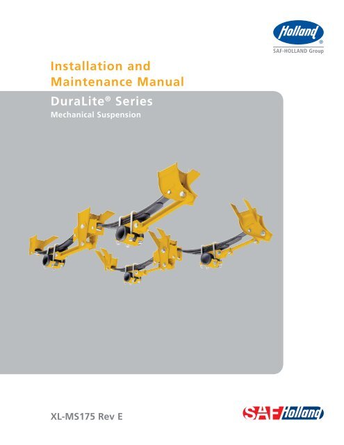
Installation andMaintenance ManualDuraLite ® SeriesMechanical Suspension<strong>XL</strong>-<strong>MS175</strong> Rev E
Table of ContentsContentsPageIntroduction ......................................................................... 2Warranty .............................................................................. 2Notes, Cautions, and Warnings ............................................. 2Section 1 – General Safety Instructions ................................ 3Section 2 – Installation Preparation ..................................... 3Section 3 – Welding Standards ............................................. 4Section 4 – Trailer Frame Hanger Brackets Location .............. 5Under Mount Hanger Brackets Installation ......... 6Flange Mount Hanger Brackets Installation ........ 7Straddle Mount Hanger Brackets Installation ...... 8Side Mount Hanger Brackets Installation ............ 9Straddle/Under Mount Brackets Installation ..... 10ContentsPageSection 5 – Weld Axle Seats to Axle(s) InstructionsOverslung Axle Style ........................................ 11Underslung Axle Style ...................................... 12Section 6 – Leaf Springs and Torque Arms AssemblyOverslung Axle Style ........................................ 13Underslung Axle Style ...................................... 14Section 7 – Axle Alignment ................................................ 15Section 8 – Final Inspection ............................................... 15Section 9 – Operating Recommendations ........................... 15Section 10 – Maintenance Recommendations ..................... 16Section 11 – Leaf Spring Selection...................................... 17Section 12 – Mounting Height Spring Seat Selections ......... 17IntroductionThis manual provides you basic information necessary for theinstallation and maintenance of the DuraLite ® suspension.IMPORTANT: It is the responsibility of the installerto determine the proper location ofthe suspension on the frame, providean adequate structure to support thesuspension, ensure adequate clearanceswith other components, and to determineif the rated suspensions and axle capacityare adequate for the trailer applications.WarrantyRefer to the complete warranty for the country in which theproduct will be used. A copy of the written warranty is includedwith the product and can be found on the SAF-HOLLANDwebsite (www.safholland.us).Notes, Cautions, and WarningsYou must read and understand all of the safety procedurespresented in this manual before starting any work onthe suspension.Proper tools must be used to perform the maintenance andrepair procedures described in this manual. Many of theseprocedures require special tools.NOTE: In the United States, workshop safety requirementsare defined by federal and/or state OccupationalSafety and Health Act. Equivalent laws may existin other countries. This manual is written basedon the assumption that OSHA or other applicableemployee safety regulations are followed by thelocation where work is performed.Failure to follow the instructions andsafety precautions in this manual canresult in death or serious injury.Throughout this manual, you will notice the terms “NOTE”,“IMPORTANT”, “CAUTION”, and “WARNING” followedby important product information. So that you may betterunderstand the manual, those terms are as follows:NOTE: <strong>Inc</strong>ludes additional information to enable accurateand easy performance of procedures.IMPORTANT: <strong>Inc</strong>ludes additional information thatif not followed could lead to hinderedproduct performance.Used without the safety alert symbol,indicates a potentially hazardoussituation which, if not avoided, couldresult in property damage.Indicates a potentially hazardoussituation which, if not avoided, couldresult in minor or moderate injury.Indicates a potentially hazardoussituation which, if not avoided, couldresult in death or serious injury.IMPORTANT: Read this manual before using thisproduct. Keep this manual in a safelocation for future reference.2<strong>XL</strong>-<strong>MS175</strong> Rev E · 2013-01-01 · Amendments and errors reserved. © SAF-HOLLAND, <strong>Inc</strong>.
General Installation Information1. General Safety InstructionsRead and observe all Warning and Caution hazard alertmessages in this publication. They provide informationthat can help prevent serious personal injury, damage tocomponents, or both.Failure to properly support the vehicle andaxles prior to commencing work couldcreate a crush hazard which, if not avoided,could result in death or serious injury.Please observe the following safety instructions in order tomaintain the operational and road safety of the suspension system.1. Only the wheel and tire sizes approved by the trailerbuilder may be used.2. Before operating vehicle, ensure that the maximumpermissible axle load is not exceeded and that theload is distributed equally and uniformly.3. Observe the operating recommendation of the trailermanufacturer for off-road operation of the installed suspension.IMPORTANT: The definition of OFF-ROAD means drivingon non-asphalted/non-concreted routes, e.g.gravel roads, agricultural and forestry tracks,on construction sites and in gravel pits.IMPORTANT: Off-road operation of suspensions beyondthe approved application design couldresult in damage and impair suspensionsystem performance.4. All suspension systems require routine service, inspectionand maintenance in order to maintain optimumperformance and operational safety as well as anopportunity to recognize wear.5. In the event of suspension component failure, quicklyreduce speed as safely as possible and remove thevehicle from traffic. If unable to remove vehicle fromtraffic, follow DOT safety requirements regardingemergency situations.6. Contact a qualified towing and/or service company toassist in repairing vehicle or to move it to a qualifiedrepair facility.We highly recommend the use of only SAF-HOLLANDOriginal Parts.2. Installation PreparationThe proper installation of the suspension is critical to assuretrouble free operation. Before proceeding with suspensioninstallation, check the tire size and trailer design to make surethat there is lateral tire clearance and a vertical tire clearanceof at least 4-1⁄2" (114 mm) when the trailer is empty.Failure to maintain tire clearance betweentires and the nearest point of contact on thesuspension or vehicle could cause fire orloss of vehicle control which, if not avoided,could result in death or serious injury.Vertical tire clearance may be adjusted by using different heightspring seats or high, medium or low arch springs. HOLLANDDuraLite suspensions are rated at 22,400 pounds (358,400 kg)GAWR (Gross Axle Weight Rating) with one, two or three leafsprings and 24,000 lbs. (384,000 kg) GAWR with heavy dutyleaf springs. (SAF-HOLLAND does not supply springs.)For leaf spring selection and mounting height information,refer to appropriate Table in Section 12. Check that adequateclearance is provided to all components of the trailer, includingbut not limited to tires, brakes and air lines.IMPORTANT: The suspension hangers must be on thesame centers as the spring seats andsprings, within the tolerances shown. Thesprings must be square with the axles andlocated the same distance from the axlecenterline within the tolerances shown.IMPORTANT: Improperly installed suspensioncomponents can lead to the followingtrailer problems: trailer lean, impropertracking, premature tire wear andshortened suspension life.Failure to correctly install suspensioncomponents will reduce suspensionperformance which, if not avoided, couldresult in premature suspension failure.A list of SAF-HOLLAND technical support locations to supplySAF-HOLLAND Original Parts can be found at www.safholland.usor contact SAF-HOLLAND Customer Service at 888-396-6501.Updates to this manual will be published as necessary onlineat www.safholland.us.<strong>XL</strong>-<strong>MS175</strong> Rev E · 2013-01-01 · Amendments and errors reserved. © SAF-HOLLAND, <strong>Inc</strong>. 3
Welding Standards3. Welding Standards3.1 ScopeYour SAF-HOLLAND suspension has been designed to beinstalled onto a trailer frame. When welding the suspensionobserve the requirements below. Customers may not weldon an SAF-HOLLAND suspension without our prior approval,including the application of the American Welding Societystandards by SAF-HOLLAND engineering. This specificationapplies to all components supplied by SAF-HOLLAND, and itsproducts. The customer assumes all responsibility for weldintegrity if weld material and procedure differ from thoselisted below.3.2 MaterialFrame attachment components made from low carbon orhigh strength alloy steel are to be welded with AWS fillermetal specification AWS A5.18, filler metal classificationER-70S-3, ER-70S-6 or equivalent unless specified on theinstallation drawing.NOTE: Any substitution for filler material from the abovestandard must comply, as a minimum, with thefollowing mechanical properties:Tensile Strength - 72k psi (496 MPa)Yield Strength - 60k psi (414 MPa) o F (-17.7o C)% Elongation - 22%The recommended welding gas for gas metal arc welding(GMAW) is 90% Argon / 10% CO2. If a different gas is used,welds must comply with penetration requirements in shownbelow. Where the installation drawing specifies different thanabove, the drawing shall prevail.3.3 ProceduresTack welds used for positioning components are to be locatedin the center of the final weld, where practical. Tack weld shouldbe completely fused to the finish weld. DO NOT break arc at theend of the weld. Back up all finish welds at least 1/2" (12 mm)or a sufficient amount to prevent craters at the end of the weld.Where weld is shown to go around corners, it is assumed thecorner represents a stress concentration area. DO NOT startor stop weld within 1" (25 mm) of the corner. Particular careshould be taken to prevent undercutting in this area.3.4 WorkmanshipIt is the responsibility of the Customer to provide good workmanshipwhen attaching components to the frame structure.3.5 Weld SizeIf weld size is not specified, the effective throat of the weldmust be a minimum of the thinnest material being welded(Figure 1).Figure 1PENETRATION AS MEASUREDTHROUGH SEAMLACK OF FUSION OF ANYKIND IN THIS AREA IS NOTACCEPTABLE AT ANY TIMETARGET PENETRATION TO BE10% OF THINNEST MATERIALFROM INTERSECTION OF FILLETAS SHOWNTARGET PENETRATION4<strong>XL</strong>-<strong>MS175</strong> Rev E · 2013-01-01 · Amendments and errors reserved. © SAF-HOLLAND, <strong>Inc</strong>.
Installation Instructions4. Trailer Frame Hanger BracketsLocation – All StylesThe DuraLite suspension is available in five hanger bracketmounting styles: under mount, flange mount, straddle mount,side mount and straddle/under mount. The DuraLite suspensionmay be used as a single axle, tandem axle or triple axle.The base suspension is the single axle – adding a multi-axleconversion kit converts the single axle to a tandem and asecond multi-axle kit will make a triple axle suspension. TheDuraLite suspension is available in overslung (axle below thespring) or underslung (axle above the spring) configuration.NOTE: The following instructions for hanger bracketlocation apply to all hanger bracket styles listedabove. After the hanger brackets have beenproperly located and tack welded to the trailerframe, proceed to the appropriate bracket typein this section for installation instructions.1. Measure and mark hanger bracket locations on bottomof trailer frame referencing the dimensions provided forsingle axle (Figure 2a), tandem axle (Figure 2b) ortriple axle (Figure 2c).Figure 2Figure 2a (Under mount style shown) center line of hanger (Figure 2). distance from the center hanger and should not vary fromdimension shown more than plus or minus 1/16" (1 mm). in exactly the same distances from front and rear oftrailer frame. of or behind corresponding hangers on other side ofsub-frame by more than plus or minus 1/16" (1 mm).IMPORTANT: Frame surface where hanger brackets areto be attached must be clean and free ofany surface rust. Use wire brush or light-dutygrinder to clean surface.2. Position hanger brackets on frame according to locationmarks determined in Step 1. Position and tack weld allhangers in position and double check dimensions beforecompleting welding of hangers (Figure 2a, 2b and 2c).IMPORTANT: Hangers must be mounted in properalignment with one another and mustnot be cocked or tilted in respect to thesub frame mounting surface.C L19"(483 mm)FRONT36-1/2" ± 1/16" (927 mm ± 1 mm)Figure 2b (Under mount style shown)C LC LFRONT19"(483 mm)24-1/2"(622 mm)43-1/2" ± 1/16" (1,105 mm ± 1 mm)43-1/2" ± 1/16" (1,105 mm ± 1 mm)Figure 2c (Under mount style shown)C L C L C LFRONT19"(483 mm)24-1/2"(622 mm)24-1/2"(622 mm)49" (1,245 mm)49-3/4" (1,245 mm)43-1/2" ± 1/16"(1,105 mm ± 1 mm)49-3/4" ± 1/16"(1,264 mm ± 1 mm)136-3/4" (3,472 mm)REF43-1/2" ± 1/16"(1,105 mm ± 1 mm)<strong>XL</strong>-<strong>MS175</strong> Rev E · 2013-01-01 · Amendments and errors reserved. © SAF-HOLLAND, <strong>Inc</strong>. 5
Installation InstructionsUnder Mount Hanger Brackets InstallationNOTE: For flange, straddle, sidemount or straddle/understyle brackets installation, refer to specific instructionslater in this section.IMPORTANT: The under mount style hanger bracketsmust be located on the trailer frame tomatch the axle spring center (Figure 3).1. Install a 1-1⁄4"schedule 40 pipe or 1.66 O.D. x .109 standardmechanical tubing through the front and center hangers.The pipe brace should be 6" (152 mm) longer than the springcenters that will provide approximately 3" (76 mm) of pipe toprotrude equally on each side. Tack weld the pipe bracein place (Figure 3).2. Add 3⁄16" (4 mm) minimum diagonal braces between thefront, center and rear hangers and the frame of the trailer(Figure 3).3. Re-verify position of hanger and pipe bracket.4. Weld the suspension hangers in place (Figures 4a, 4band 4c). Weld the pipe braces and diagonal braces inplace (Figure 3).Figure 3XXXXXXXXXXXXXXXXXXXXXXDIAGONAL BRACES REQUIRED ONFRONT, CENTER & REAR HANGERS(NOT INCLUDED)XXXXXXXXXXXXXXXXXXXXXX183( ) 34 4XXXXXXXXXXXXX183163( ) 34 4TYP1-1/4" PIPE – SCHEDULE 40OR 1.66 O.D. X .109 TUBING(NOT INCLUDED)WELD TUBE INSIDE WITH 3/4 WELDS ON THEHORIZONTAL CENTER LINE OF THE TUBE, ASSHOWN ON FRONT & CENTER HANGERS.SPRING CENTERS ±1/16" (1 mm)XXXXXXXXXXXXXXX183( ) 34 4Figure 4Figure 4a3165-1/2STOP WELDS 1/4" (6 mm)FROM EDGEFigure 4b3167-1/2STOP WELDS 1/4" (6 mm)FROM EDGEXXXXXXXXXXXXXXXXXXXXXXXXXXXXXXXXXXXXXXXXXXXXXXXXXXXXXXXXX3163-1/23-1/2316 3-1/2Figure 4c3STOP WELDS 1/4" (6 mm)FROM EDGE16 4-1/2 316XXXXXXXXXXXXXX3-1/2XXXXXXXXX6<strong>XL</strong>-<strong>MS175</strong> Rev E · 2013-01-01 · Amendments and errors reserved. © SAF-HOLLAND, <strong>Inc</strong>.
Installation InstructionsFlange Hanger Brackets Installation1. Install a 1-1⁄4"schedule 40 pipe or 1.66 O.D. x .109 standardmechanical tubing through the front and center hangers.The pipe brace should be 6" (152 mm) longer than thespring centers that will provide approximately 3" (76 mm)of pipe to protrude equally on each side. Tack weld the pipebrace in place (Figure 5).2. Add 3⁄16"(4 mm) minimum diagonal braces between thefront, center and rear hangers and the frame of the trailer(Figure 5).3. Re-verify position of hanger and pipe bracket.4. Weld the suspension hangers in place (Figures 6a, 6band 6c). Weld the pipe braces and diagonal braces inplace (Figure 5).Figure 5DIAGONAL BRACES REQUIRED ONFRONT, CENTER & REAR HANGERS(NOT INCLUDED)XXXXXXXXXXXXXXXXXXXXXXXXXXXXXXXXXXXXXXXXXXXXXXXX183( ) 34 4XXXXXXXXXXXX183163( ) 34 4TYPWELD TUBE INSIDE WITH 3/4" WELDS ON THEHORIZONTAL CENTER LINE OF THE TUBE, ASSHOWN ON FRONT & CENTER HANGERS.SPRING CENTERS ±1/16" (1 mm)XXXXXXXXXXXX183( ) 34 4Figure 6Figure 6a 316Figure 6b316XXXXXXXXXXXXXXXXXXXXXXXXXXXXXXXXXXXXXXXXXXXXXXXXXXXXXXXXXXXXXXXXXXXXXXXXXXXXXXXXXXXXXXXXXXXXXXXXXXXXXXXXXXXXXXXXXXXXXXXXXXXXXFigure 6c 316XXXXXXXXXXXXXXXXXXXXXXXXXXXXXXXXXXXXXXXXXXXXXXXXXXXXXXXXXXXXXXX<strong>XL</strong>-<strong>MS175</strong> Rev E · 2013-01-01 · Amendments and errors reserved. © SAF-HOLLAND, <strong>Inc</strong>. 7
Installation InstructionsStraddle Hanger Brackets Installation1. Install a 1-1⁄4" schedule 40 pipe or 1.66 O.D. x .109 standardmechanical tubing through the front and center hangers.The pipe brace should be 6" (152 mm) longer than thespring centers that will provide approximately 3" (76 mm)of pipe to protrude equally on each side. Tack weld the pipebrace in place (Figure 7).2. Re-verify position of hanger and pipe bracket.3. Weld the suspension hangers in place (Figures 8a, 8band 8c). Weld the pipe braces in place (Figure 7).Figure 7183( ) 34 4XXX 183( )434WELD TUBE INSIDE WITH 3/4 WELDS ON THEHORIZONTAL CENTER LINE OF THE TUBE, ASSHOWN ON FRONT & CENTER HANGERS.XXXX183( ) 34 4SPRING CENTERS ±1/16" (1 mm)183( ) 34 4Figure 8Figure 8aFigure 8bWELD NO. 1TACK WELD 4 PLCSPER HANGERWELD NO. 2TYP 2 PLCS PER HANGER(WELDS MUST BECONTINUOUS - DO NOTSTOP AND RESTART)Figure 8cBEGIN WELDS HERE316TIE THIS WELDINTO WELD #2316BEGIN WELDS HERECCWELD NO. 3TYP 2 PLCS PER HANGER (WELDS MUST BECONTINUOUS - DO NOT STOP AND RESTART)ALL VERTICAL WELDS ARE BEVELWELDS INSTEAD OF FILLETS ANDFLUSH AS SHOWN.SECTION C-CTYP 12 PLCS8<strong>XL</strong>-<strong>MS175</strong> Rev E · 2013-01-01 · Amendments and errors reserved. © SAF-HOLLAND, <strong>Inc</strong>.
Installation InstructionsSide Mount1. Install a 1-1⁄4" schedule 40 pipe or 1.66 O.D. x .109 standardmechanical tubing through the front and center hangers.The pipe brace should be 6" (152 mm) longer than thespring centers that will provide approximately 3" (76 mm)of pipe to protrude equally on each side. Tack weld the pipebrace in place (Figure 9).2. Re-verify position of hanger and pipe bracket.3. Weld the suspension hangers in place (Figures 10a, 10band 10c). Weld the pipe braces in place (Figure 9).Figure 9WELD TUBE WITH 3/4" WELDS ON THE HORIZONTALCENTER LINE OF THE TUBE, AS SHOWN ON FRONT& CENTER HANGERS.183( ) 34 4183( ) 34 41-1/4" PIPE - SCHEDULE40 OR 1.66" O.D. X .109"TUBING (NOT INCLUDED)SPRING CENTERS ±1/16" (1 mm)Figure 10Figure 10aFigure 10b316FRONT SIDEMOUNTHANGER BRACKETS316REAR SIDEMOUNTHANGER BRACKETSFigure 10c316.50" NOWELD TYPCENTER SIDEMOUNTHANGER BRACKETS.50" NOWELD TYP.50" NOWELD TYP<strong>XL</strong>-<strong>MS175</strong> Rev E · 2013-01-01 · Amendments and errors reserved. © SAF-HOLLAND, <strong>Inc</strong>. 9
Installation InstructionsStraddle/Under Mount1. Install 3/16” thick angle braces at Front, Center, and Rearhangers. Brace should be at approximately a 45° angleand extend at least to the mid-point of the hanger. Tackweld the braces in place. (Figure 11).2. Re-verify position of hanger and angle braces.3. Weld the suspension hanger brackets in place (Figures 12a,and 12b). Weld the angle braces in place (Figure 11).Figure 11DIAGONAL BRACES REQUIRED ON FRONT,CENTER AND REAR HANGERS (NOT INCLUDED)3/16"TYPSPRING CENTERS ±1/16" (1 mm)Figure 12Figure 12aFRONT AND REAR STRADDLE HANGER BRACKETSFigure 12bCENTER UNDERMOUNT HANGER BRACKETS3/16" 7-1/2"3/16"WELD NO. 1TACK WELD 4 PLCSPER HANGERCCWELD NO. 4(WELDS MUST BE CONTINUOUS -DO NOT STOP AND RESTART)3/16"TYPWELD NO. 2 WELD NO. 3BEGIN WELDS HERE3/16" TYPTYP3/16"SECTION C-CTYP 12 PLACESALL VERTICAL WELDS ARE BEVELWELDS INSTEAD OF FILLETS ANDFLUSH AS SHOWN.3/16"3-1/2"STOP WELDS1/4" FROM EDGE3/16"3-1/2"10<strong>XL</strong>-<strong>MS175</strong> Rev E · 2013-01-01 · Amendments and errors reserved. © SAF-HOLLAND, <strong>Inc</strong>.
TYP 14X X XXXXXXXXXXXXXXXInstallation Instructions5. Weld Axle Seats To Axles InstructionsFigure 13IMPORTANT: The axle seats and bottom plates that arewelded to the axle are compatible with alllow hydrogen welding processes suitablefor welding to steel axles.Overslung Axle Style1. The axle seats should be located on the spring centers within.06" (1 mm). The axle seats should be the same distance fromthe center of the axle within .03" (.7 mm). The camshaftshould be oriented per the axle manufacturer´s specification.NOTE: When the cams are forward, the cam must bebelow the horizontal centerline when axle seatsof 2" (51 mm) or shorter height are used.CORRECTA<strong>XL</strong>E BOTTOM PLATEMUST CONTACT A<strong>XL</strong>EAS SHOWNINCORRECTNOT ACCEPTABLE2. Clamp the axle seats and bottom plates to the axle. Theaxle MUST contact the axle seat and bottom plate at thetop and bottom center of the adapters or contact at leasttwo points no more than 1-1/2" (38 mm) from center ofthe axle (Figure 13).3. Verify correct connection. Using a .006" (0.15 mm) feelergage be sure it is NOT able to slide between axle andspring seat or bottom plate more than 1/4" (6 mm) incontact area (Figure 14). If a greater gap is present,these parts may be clamped to the axle or adjusted tofit by grinding the axle seat.Failure to maintain proper clearancebetween the axle and parts welded toit may result in premature weld failure,which if not avoided, could result in deathor serious injury.Figure 141-1/2"(38 mm)NO WELDXX X X XX XX X X X XXXX1-1/2"(38 mm)NO WELDCONTACT AREAXX X X X XXXXXXXXXXXXXXXXXXX4. Following the axle manufacturer’s recommendations,weld the axle seats and bottom plates to the axles(Figure 14).2-3/4"(70 mm)NO WELDCONTACT AREA2-3/4"(70 mm)NO WELD1"(25 mm)XXXXXXXXXXXXXXXXXXXXXXXXXXXXXXXXXXXXXXXXXXXXXXXXXXXXX1/2" TYP(13 mm)XXXXXXXXXXXXXX1/2" TYP(13 mm)XXXXXX<strong>XL</strong>-<strong>MS175</strong> Rev E · 2013-01-01 · Amendments and errors reserved. © SAF-HOLLAND, <strong>Inc</strong>. 11
TYP 14Installation InstructionsUnderslung Axle StyleIMPORTANT: The axle seats and bottom plates that arewelded to the axle are compatible with alllow hydrogen welding processes suitablefor welding to steel axles.1. The axle seats should be located on the spring centers within.06" (1 mm). The axle seats should be the same distancefrom the center of the axle within .03" (.7 mm). The camshaftshould be oriented per the axle manufacturer’s specification.NOTE: When the cams are forward, the cam must bebelow the horizontal centerline when axle seatsof 2" (51 mm) or shorter height are used.2. Clamp the axle seats and bottom plates to the axle. Theaxle MUST contact the axle seat and bottom plate at thetop and bottom center of the adapters or contact at leasttwo points no more than 1-1/2" (38 mm) from center ofthe axle (Figure 15).3. Verify correct connection. Using a .006" (0.15 mm) feelergage be sure it is NOT able to slide between axle andspring seat or bottom plate more than 1/4" (6 mm) incontact area. If a greater gap is present, these parts maybe clamped to the axle or adjusted to fit by grinding theaxle seat.Failure to maintain tire clearance betweentires and the nearest point of contact on thesuspension or vehicle could cause fire orloss of vehicle control which, if not avoided,could result in death or serious injury.Figure 15CORRECTA<strong>XL</strong>E BOTTOM PLATEMUST CONTACT A<strong>XL</strong>EAS SHOWNFigure 16X X X X XINCORRECTNOT ACCEPTABLEX X X XX4. Following the axle manufacturer’s recommendations,weld the axle seats and bottom plates to the axles(Figure 16).2-3/4" (70mm)NO WELDCONTACT AREA2-3/4" (70mm)NO WELD1"(25mm)XXXXXXXXXXXXXXXXXXXXXXXXXXXXXXXXXXX12<strong>XL</strong>-<strong>MS175</strong> Rev E · 2013-01-01 · Amendments and errors reserved. © SAF-HOLLAND, <strong>Inc</strong>.
Installation Instructions6. Leaf Springs and Torque Arms AssemblyOverslung Axle StyleFigure 17U-BOLTSNOTE: It is recommended that fasteners be installed withthe nuts on the outside (closest to tires).NOTE: Torque specifications are with clean lubricated/coatedthreads. All new SAF-HOLLAND fasteners comepre-coated from the factory.IMPORTANT: The use of special lubricants with frictionmodifiers, such as Anti-Seize or Never-Seize,without written approval from SAF-HOLLANDEngineering, will void warranty and couldlead to over torquing of fasteners or othercomponent issues.Torque Arms and Springs Installation1. Position the supplied spring liner on top of the springsand set it on top of the axle spring seat (Figure 17).Place the top plate on top of the spring.2. Install the springs on the axles with the appropriate U-bolts,nuts and washers. The U-bolts will fit into the detentsstamped into the top plate (Figure 17).IMPORTANT: On tandem axle suspensions the big hookend of the spring should be arranged tofit in the equalizer (Figure 18a). On singleaxle suspensions it should point to the rear(Figure 18). Arrange the springs so thatthey are on the correct centers ±.03" (1 mm)and perpendicular to the axle. torque using an alternating pattern (Figure 17a). Checkthe spring centers and adjust if necessary.DO NOT hit steel parts with a steelhammer as parts could break, sendingflying steel fragments in any directioncreating a hazard which, if not avoided,could result in minor to moderate injury.4. Install the axles with springs into the suspension hangers.Install the 5/8" spring retainer bolts and spacers in thefront and rear hangers, and the equalizer on tandemaxles to hold the springs in place. Tighten 5/8" bolts to(Figure 18).IMPORTANT: DO NOT overtighten as this may damagethe spacers.5. Install the torque arms between the hangers and the springseats on the axles. It is recommended that the adjustabletorque arms be installed on the roadside and the fixed (cast)torque arms be installed on the curbside (Figure 19). Installthe 7/8" nuts and bolts to secure the torque arms in place(Figure 19).6. With the suspension installed, check that there is 1/8" ± 3/32"(3 mm ± 2 mm) clearance between the springs and the sidesof the hangers and that all the springs are contacting thebottoms of the hangers (Figure 19a).7. Position the decal, <strong>XL</strong>-MS189-01, in clear view on the roadsideof the vehicle as close as practical to the suspension.SMALLHOOKFigure 18SMALLHOOKFigure 19TOPPLATESPRING SEATADJUSTABLE TORQUEARM TO ROADSIDEFIXED (CAST) TORQUEARM TO CURBSIDE7/8" TORQUE ARM BOLTS275-300 FT.-LBS. TORQUEm)SPRINGLINERFigure 17aU-BOLTTORQUESEQUENCE275-300 FT.-LBS.m)SPRING RETAINER BOLTS & SPACERSm)Figure 18aBIGHOOKFigure 19a1/8" ± 3/32"(3 mm-1 mm)GAP ON BOTHSIDES OF THESPRINGBIG HOOKEND OF SPRINGBIG HOOKEND OF SPRINGEQUALIZERBIGHOOK<strong>XL</strong>-<strong>MS175</strong> Rev E · 2013-01-01 · Amendments and errors reserved. © SAF-HOLLAND, <strong>Inc</strong>. 13
Installation InstructionsUnderslung Axle StyleFigure 20NOTE: It is recommended that fasteners be installed withthe nuts on the outside (closest to tires).NOTE: Torque specifications are with clean lubricated/coatedthreads. All new SAF-HOLLAND fasteners comepre-coated from the factory.Torque Arms and Springs Installation1. Assemble the springs. Position the supplied spring lineron top of the springs and set it on top of the axle springseat (Figure 9). Place the top plate on top of the spring.2. Install the springs to the axles with the appropriateU-bolts, nuts and washers.SMALLHOOKBOTTOMPLATEU-BOLTFigure 20aU-BOLTTORQUESEQUENCE275-300 FT.-LBS.m)SPRINGLINERBIG HOOKEND OF SPRINGIMPORTANT: On tandem axle suspensions the big hookend of the spring should be arranged to fitin the equalizer (Figure 21a). On singleaxle suspensions it should point to the rear(Figure 21). Arrange the springs so thatthey are on the correct centers ±.03" (1 mm)and perpendicular to the axle. of torque using an alternating pattern (Figure 20a).Check the spring centers and adjust if necessary.DO NOT hit steel parts with a steelhammer as parts could break, sendingflying steel fragments in any directioncreating a hazard which, if not avoided,could result in minor to moderate injury.4. Install the axles with springs into the suspension hangers.Install the 5/8" spring retainer bolts and spacers in thefront and rear hangers, and the equalizer on tandemaxles to hold the springs in place. Tighten 5/8" bolts(Figure 21).Figure 21SMALLHOOKSPRING RETAINER BOLTS & SPACERSm)Figure 21aBIGHOOKBIG HOOKEQUALIZERBIGHOOKIMPORTANT: DO NOT overtighten as this may damagethe spacers.5. Install the torque arms between the hangers and thebottom plates on the axles. It is recommended that theadjustable torque arms be installed on the roadsideand the fixed torque arms be installed on the curbside(Figure 22). Install the 7/8" nuts and bolts to securethe torque arms in place and torque to 275-300 ft.-lbs.(Figure 22).6. With the suspension installed, check that there is 1/8" ± 3/32"(3 mm ± 2 mm) clearance between the springs and the sidesof the hangers and that all the springs are contacting thebottoms of the hangers (Figure 22a).7. Position the decal, <strong>XL</strong>-MS189-01 in clear view on the roadsideof the vehicle as close as practical to the suspension.Figure 227/8" TORQUE ARM BOLTS275-300 FT.-LBS. TORQUEm)ADJUSTABLE TORQUEARM TO ROADSIDEFIXED (CAST) TORQUEARM TO CURBSIDEFigure 22a1/8" ± 3/32"(3 mm – 1 mm)GAP ON BOTHSIDES OF THESPRING14<strong>XL</strong>-<strong>MS175</strong> Rev E · 2013-01-01 · Amendments and errors reserved. © SAF-HOLLAND, <strong>Inc</strong>.
Axle Alignment7. Axle AlignmentIMPORTANT: Axle alignment should always be donewhile the trailer is empty.1. Pull the trailer in a straight line for a sufficient distanceto ensure there are no binds in the suspension.2. Engage the trailer park brakes.3. Check that the ends of the springs are contacting thebottom wear pads in all hangers.4. Loosen the 5/8" clamp bolts on the adjustable torque arms.5. Disengage the trailer parking brakes and ensure thetrailer is empty.6. Manually measure or use an optical device specificallydesigned for alignment measuring to determine the following:a. Measure the distance from the king pin tothe centerline of the front axle spindles. It isrecommended that spindle extensions be utilized.b. Dimensions A and B (Figure 23) must be equal towithin 1/8" (3 mm).c. Measure the distance from the centerline of the frontaxle spindles to the centerline of the rear axle spindles.d. Dimensions C and D (Figure 23) must be equal towithin 1/16" (1 mm).7. Tighten the clamp bolts on the adjustable torque arm to8. Final Inspection1. Verify that the hanger brackets to mounting sub-frame andaxle seat welds have been completed per specifications,refer to Section 4.2. Check all suspension fastener connections for propertorque settings (Figures 25).3. Check adjustable torque arm clamp nuts to be certain that4. Check for proper suspension mounting height.5. Check for proper 4-1⁄2" (114 mm) vertical tire clearance(Figure 24).6. Verify that the front axle alignment does not exceed amaximum variation of 1/8" (3 mm) kingpin to front axleand a maximum variation of 1/16" (1 mm) axle to axleon any additional axles (Figure 15).9. Operating Recommendations1. Observe the operating recommendation of the trailermanufacturer for off-road operation of the installed axles,refer to Section 1.Figure 23KINGPINFigure 24ADJUSTABLETORQUE ARMCLAMP NUTS85-95 FT.-LBS.m)B=A ± 1/8" (3 mm)AB4-1/2"(114 mm)C=D ± 1/16" (1 mm)CDCHECK FOR PROPERTIRE CLEARANCESUSPENSION MOUNTINGHEIGHTOVERSLUNG A<strong>XL</strong>E STYLE SHOWN<strong>XL</strong>-<strong>MS175</strong> Rev E · 2013-01-01 · Amendments and errors reserved. © SAF-HOLLAND, <strong>Inc</strong>. 15
Maintenance Recommendations10. MaintenanceDuraLite ® suspensions, by design, require a minimum ofmaintenance. However, suspensions in “over-the-road”operations require periodic checks to be certain of continuedtrouble free performance.miles (1,609 km), re-check the trailer alignment andcorrect, if required.it is fully operational.intact. Clean with a terry cloth towel, soap and water.of suspension is required every six months or 25,000miles (40, 234 km), whichever comes first.(Figure 25), should bere-torqued to the following specifications.NOTE: Failure to maintain proper fastener torque valuescould result in suspension component damage andloss of vehilce control which, if not avoided, couldresult in death or serious injury.IMPORTANT: The use of special lubricants with frictionmodifiers, such as Anti-Seize or Never-Seize,without written approval from SAF-HOLLANDEngineering, will void warranty and couldlead to over torquing of fasteners or othercomponent issues.1. Check 3/4"-16 U-bolt nuts to be certain that 275-300 ft.-lbs.2. Check 1-14" equalizer bolt to be certain that 450-500 ft.-lbs.3. Check 7/8"-14 torque arm bolts to be certain that4. Check adjustable torque arm clamp nuts to be certain that5. Check spring retainer bolts to be certain that 35-50 ft.-lbs.Loose, damaged, or missing fastenerscan cause loss of vehicle control which,if not avoided, could result in death orserious injury.Figure 25Overslung Axle Model255341Underslung Axle Model5534116<strong>XL</strong>-<strong>MS175</strong> Rev E · 2013-01-01 · Amendments and errors reserved. © SAF-HOLLAND, <strong>Inc</strong>.
Leaf Spring Selection11. Leaf Spring SelectionFailure to maintain tire clearance between tires and the nearest point of contact on the suspension or vehicle couldcause fire or loss of vehicle control which, if not avoided, could result in death or serious injury.SAF-HOLLAND DuraLite suspensions are rated up to 25,000 lbs. (11,340 kg) GAWR with proper springs, axles and brakes. Thefollowing widely available SAF-HOLLAND leaf springs are suitable for use with DuraLite suspensions:SPRING TYPE SINGLE LEAF TWO LEAF THREE LEAFTHREE LEAFHDLow Arch SP0363 SP0326 SP0356 SP9365-01Medium Arch – SP0325 SP0355 –High Arch** SP0360* SP0324 SP0354 SP0365* Not approved for single axle applications.** SAF-HOLLAND does NOT recommend use of high arch springs in single axle applications.IMPORTANT: It is the installer’s responsibility to select the correct mounting height. There should be 4-1⁄2" (114 mm) ofvertical tire clearance with an unloaded vehicle. In addition, clearance must be provided at the side, front, andrear of the tires to prevent tire contact during suspension movement. The mounting heights, shown below, arenominal values and may vary due to variations in the leaf springs and other components.<strong>XL</strong>-<strong>MS175</strong> Rev E · 2013-01-01 · Amendments and errors reserved. © SAF-HOLLAND, <strong>Inc</strong>. 17
Notes18<strong>XL</strong>-<strong>MS175</strong> Rev E · 2013-01-01 · Amendments and errors reserved. © SAF-HOLLAND, <strong>Inc</strong>.
Notes<strong>XL</strong>-<strong>MS175</strong> Rev E · 2013-01-01 · Amendments and errors reserved. © SAF-HOLLAND, <strong>Inc</strong>. 19
From fifth wheel rebuild kits to suspension bushing repair kits,SAF-HOLLAND Original Parts are the same quality components usedin the original component assembly.SAF-HOLLAND Original Parts are tested and designed to providemaximum performance and durability. Will-fits, look-a likes or, worseyet, counterfeit parts will only limit the performance potential andcould possibly void SAF-HOLLAND’s warranty. Always be sure to specSAF-HOLLAND Original Parts when servicing yourSAF-HOLLAND product.SAF-HOLLAND USA · 888.396.6501 · Fax 800.356.3929www.safholland.usSAF-HOLLAND CANADA · 519.537.3494 · Fax 800.565.7753WESTERN CANADA · 604.574.7491 · Fax 604.574.0244www.safholland.caSAF-HOLLAND MEXICO · 52.55.5362.8743 · Fax 52.55.5362.8743www.safholland.com.mxinfo@safholland.com<strong>XL</strong>-<strong>MS175</strong> Rev E · 2013-01-01 · Amendments and errors reserved. © SAF-HOLLAND, <strong>Inc</strong>.SAF-HOLLAND USA, INC.1950 Industrial Blvd, Muskegon, MI 49442www.safholland.com