BI Comb SGM.GB
BI Comb SGM.GB
BI Comb SGM.GB

You also want an ePaper? Increase the reach of your titles
YUMPU automatically turns print PDFs into web optimized ePapers that Google loves.
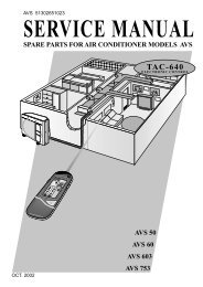
LISTINOPREZZIINDUSTRIAL BOILERS<strong>BI</strong> <strong>Comb</strong> Sgminstruction booklet
<strong>BI</strong> <strong>Comb</strong> SgmGENERAL INDEX1. TECHNICAL SPECIFICATIONS <strong>BI</strong> <strong>Comb</strong> Sgm AC-ASL-ASH2. TECHNICAL SPECIFICATIONS <strong>BI</strong> <strong>Comb</strong> Sgm HP-HP12-HP153. FUEL FEED SYSTEM3.1 Solid fuel3.1.1 Automatic hopper feed systems4. MECHANICAL FURNACE AND MO<strong>BI</strong>LE GRATE FEEDER4.1 <strong>Comb</strong>ustion logic4.2 Main components4.2.1 Storage hopper for granular fuel4.2.2 Feed screw with relative motor and drive mechanisms4.2.3 <strong>Comb</strong>ustion air fans with relative ducts4.2.4 Furnace in combustion chamber4.2.5 Mobile grate and its motor and drive mechanisms4.2.6 Ash discharge screw with its motor and drive mechanisms4.3 Fire safety4.3.1 Fire prevention system hydraulic connection diagram4.4 Continuous modulation of the heat input4.5 Use of traditional fuel, DIESEL - FUEL OIL - GAS4.5.1 Pilot burner4.5.2 Alternative burner4.6 Dumped ash removal4.6.1 Ash removal to bin4.6.2 Direct ash removal, to underground bin4.6.3 Indirect ash removal, to underground bin4.6.4 Direct ash removal, to the multiple centrifugal dust separator4.7 Soot blowers5. INITIAL COMMISSIONING5.1 Initial commissioning procedure5.2 Boiler shut-down procedure5.3 Start-up5.4 Special calibration for the modulating model5.5 Calibrating the automatic draught register5.6 Operating tests on the pressurised part5.7 Cleaning the combustion grate3
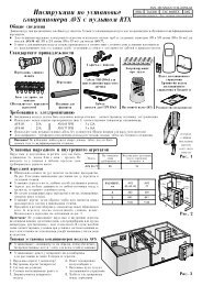
1. TECHNICAL SPECIFICATIONS <strong>BI</strong> <strong>Comb</strong> Sgm AC-ASL-ASHWORKING PRESSUREASH REMOVALSCREW SIDEKey1 Boiler body2 Boiler bed3 Hopper4 Mechanical furnacea1 Supplya2 Returna3 Alternative burner attachmenta4 Pilot burner attachmenta5 Flue attachmenta6 Hopper loadinga7 Ash dump<strong>BI</strong> <strong>Comb</strong> Sgm 800 1000 1200 1600 2000 2500 3000 4000 5000Heat output kW 930 1163 1396 1861 2326 2907 3489 4652 5815Heat input kW 1163 1454 1745 2326 2907 3633 4361 5815 7268Water content dm 3 1120 1280 1560 1870 2260 2600 2990 3610 4150<strong>Comb</strong>ustion chamber volume m 3 3,8 3,8 5,3 5,3 7,7 7,7 10,3 12,5 15,4Post-combustion chamber volume m 3 4,9 4,9 5,8 5,8 7,7 9,2 10,9 15,0 17,7Actual heat exchange surface area m 2 60 74 89 116 145 170 211 265 338Mobile grate surface m 2 0,92 0,92 1,26 1,26 1,86 1,86 2,39 3,02 3,80∆p flue gas side mbar 4,6 5,6 4,6 5,6 6,6 8,7 8,7 10,7 12,2∆p water side mbar 160 180 210 250 350 390 390 420 420Installed electrical power kW 6,75 7,10 9,50 10,25 13,15 13,95 18,25 22,25 25,75Boiler weight kg 13000 14400 18900 21750 25150 28600 33300 40400 48050Boiler bed weight kg 7200 8000 9350 10500 11250 12100 13250 15250 18100Hopper weight kg 340 340 340 340 340 340 340 340 340Mechanical furnace weight kg 330 330 470 470 680 680 780 780 780a1-a2 DN 100 100 125 125 150 150 200 200 250a3max. burner nose diam. mm 207 207 240 240 270 270 300 300 360burner nose length min-max 173-273 173-273 180-280 180-280 195-295 195-295 210-310 210-310 240-340a4max. burner nose diam. mm 150 150 150 150 150 150 150 150 150burner nose length min-max 300-350 300-350 300-350 300-350 350-400 350-400 350-400 350-400 400-450a5 mm 600x300 600x300 700x350 700x350 800x400 800x400 1000x500 1200x600 1300x650a6 mm 380x170 380x170 380x170 380x170 380x170 380x170 500x230 500x230 500x230a7 Ø mm 300 300 300 300 300 300 300 300 300<strong>BI</strong> <strong>Comb</strong> Sgm A B C D E F G H L M800 2300 1960 4497 1190 970 1970 1880 3490 610 16521000 2300 1960 4897 1190 970 1970 1880 3490 610 16521200 2500 2080 5155 1260 980 2064 1970 3760 575 18761600 2500 2080 5755 1260 980 2064 1970 3760 575 18762000 2870 2280 6013 1350 990 2131 2120 4220 540 21112500 2870 2280 6661 1350 990 2131 2120 4220 540 21113000 3070 2380 7283 1430 1000 2548 2200 4500 638 24684000 3170 2560 8055 1500 1000 2618 2360 4670 527 25925000 3350 2820 8793 1570 1000 2688 2570 4920 570 28704
3. FEED SYSTEM3.1 SOLID FUELThe Bi <strong>Comb</strong> Sgm boiler is fitted with an FM series mechanicalstoker, which is calibrated during the initial testing andinspection phase. A storage hopper, placed above, feeds theboiler. The hopper must however be fed in automatic mode.3.1.1 AUTOMATIC HOPPER FEED SYSTEMSTwo diagrams are enclosed which illustrate two traditionalsolutions; the screw system is the more simple, yet can beused only for silos installed near the heating plant, while thepneumatic system can cover large distances. The conveyingsystem receives the signal to start from the level controllersfitted on the hopper, and must guarantee a feed flow rate of atleast 30% more than the maximum power consumption of theboiler, which is calculated using the formula:FEED FLOW RATE =kcal/h DELIVEREDPs x PCI x 0,8x 1,3 = m 3 /hPs = Specific weight - kg/m 3PCI = Heat power (varies from 3000-5000 kcal/kg)Fig. 1 - SCREW SYSTEMFig. 2 - PNEUMATIC SYSTEM1 Silo2 Extractor and dosing device3 Radial valve4 Conveying screw5 Grinder6 Pneumatic conveying fan7 Check valve8 Passage indicator9 Decanter dust separator10 Sleeve filter11 Radial valve12 Mechanical stoker13 Boiler6
4.2 MAIN COMPONENTSThe feeder / mobile grate system is essentially made up of:- Storage hopper for granular fuel- Feed screw with relative motor and drive mechanisms- <strong>Comb</strong>ustion air fans with relative ducts- Furnace in combustion chamber- Mobile grate and its motor and drive mechanisms- Ash discharge screw with its movement mechanisms andash dump outlet damper4.2.1 STORAGE HOPPER FOR GRANULAR FUELFeaturing a cylindrical shape, it is fitted at the base with aleaf-spring scraper, driven by a gear motor. To remove thescraper in the event of breakage or blockage, simply removethe lower disk (pos. 6). Then, from inside the hopper, lift thescraper itself. To remove the gear motor, loosen the bolts(pos. 8) and remove the lower disk.Fig. 51 SMIM SEAL RING2 BUSH3 SPACER FLANGE4 SMIM STOP FLANGE5 GEAR MOTOR SHAFT6 LOWER DISK7 LOWER DISK FASTENING SCREW8 GEAR MOTOR FASTENING BOLTS9 LEAF SPRING SUPPORT WHEEL10 LEAF SPRING PACK11 LEAF SPRING FASTENING PLATES12 GEAR MOTOR13 UPPER LEVEL CONTROLLER14 LOWER LEVEL CONTROLLER15 LEVEL INSPECTION PORTHOLE16 ACCESS HATCH17 SEAL GASKET18 HATCH CLOSED LIMIT SWITCH19 PLATE FOR SETTING AUTO FEED20 INSPECTION AND EMPTYING DOOR21 SEAL GASKET22 DISCHARGE OUTLETThe maximum and minimum level sensors are rotating paddletype, flanged on corresponding stubs. The specific installationand operation booklets are enclosed with the documentation.A timer works together with the lower level controller to activatea fuel alarm. For the relative operating logic, see thewiring diagram.9
4.2.2 FEED SCREW WITH RELATIVE MOTOR AND DRIVEMECHANISMSList of components:- High-thickness, cold pre-formed steel worm-screw, weldedonto an iron bar.- High-thickness screw-holder tube, with inspection door, flangedconnection for fastening to the hopper and fire preventionthermostat.- Adjustable speed motor unitFig. 61 SCREW2 SCREW-HOLDER TUBE3 SCREW-HOLDER TUBE INSPECTION DOOR4 FLANGE FOR ATTACHMENT TO THE BOILER BED5 FLANGE FOR ATTACHMENT TO THE HOPPER6 SEAL GASKET7 FIRE PREVENTION THERMOSTAT8 THERMOSTAT BULB9 BULB FASTENING BRACKET10 CAPILLARY PROTECTIVE SHEATH11 COUPLING FOR FIRE PREVENTION ELECTROVALVE TU<strong>BI</strong>NG12 ADJUSTABLE SPEED MOTOR FASTENING FLANGE13 INTERMEDIATE FLANGE14 GEAR MOTOR15 SPEED ADJUSTMENT HANDWHEEL16 SCREW DRIVE SHAFT17 MALE SQUARE18 FEMALE SQUARE19 SHAFT FASTENING RING20 RING FASTENING SCREW21 KEY22 THRUST BEARING23 BUSHPROCEDURE FOR REMOVING THE SCREW(to be performed in order)- Loosen the crown of bolts which fastens the adjustablespeed motor (pos. 14) to the flange (pos.12), after havingensured the weight of the motor is supported.- Move the adjustable speed motor back, removing the malesquare (pos.17) from the female square (pos. 18).At this point the screw is free to be removed. If it isblocked due to material pressed against the tube, applyleverage using the hopper inlet spout or the furnace itselfin the combustion chamber. If required, using a suitablemale square spanner and lever arm, the screw can beunscrewed from the material blocking it.10
4.2.3 COMBUSTON AIR FANS WITH RELATIVE DUCTSThese are ambient temperature-type ducts, with directly-coupledmotor. The combustion air is channelled in the metal-framedducts. The duct throttle valve is parallel with the externalarm, which rotates 90° in the sector. As a result, the throttlewill be open when the arm is positioned length-wise along theduct, and closed when it is positioned cross-wise.- PRIMARY AIR COMBUSTION FANMain primary air regulation registerDamper and counterweightUpper primary air register A3MS feeder primary air register A1Mobile grate primary air register A24.2.4 FURNACE IN COMBUSTION CHAMBERCOMPONENTS:- Welded high-thickness refractory steel trough, with stiffeningribs.- Row of grates in special cast iron, designed for high-temperatures.- Row of fixed, sloped refractory steel grates.All the grates are slotted into the structures below.To disassemble them, first remove the fixed sloped gratesby simply lifting them up, and then the mobile sloped grates,in the same way.- SECONDARY COMBUSTION AIR FANSR secondary air register above the grateL secondary air register above the grateR secondary post-combustion air registerL secondary post-combustion air registerA4A511
4.2.5 MO<strong>BI</strong>LE GRATE AND ITS MOTOR AND DRIVE MECHANISMSSECT. Y-YFig. 71 FIXED SLOPED GRATE ARCH-BARS2 MO<strong>BI</strong>LE GRATE ARCH-BARS3 END FIXED GRATE ARCH-BARS4 ASH COLLECTION <strong>BI</strong>N5 GUIDE CROSS-BEAMS FOR THE MO<strong>BI</strong>LE GRATE ARCH-BARS6 MO<strong>BI</strong>LE RACK7 MO<strong>BI</strong>LE RACK BASE BEAMS8 SADDLE9 SADDLE GUIDE10 CAM-GUIDE U-BOLT11 CAM12 BEARING13 CAM SUPPORT SHAFT14 BEARING WITH SELF-CENTRING SUPPORT15 MALE-FEMALE SQUARE TRANSMISSION JOINT16 TRANSMISSION AXLE17 ADJUSTABLE SPEED MOTOR HUB18 ADJUSTABLE SPEED MOTOR19 ADJUSTABLE SPEED MOTOR FASTENING FLANGE20 HANDWHEEL FOR MANUALLY ADJUSTING THE ADJUSTABLE SPEEDMOTOR OUTPUT SPEED12
4.2.6 ASH DISCHARGE SCREW WITH ITS MOTOR AND DRIVE MECHANISMSFig. 81 ASH DISCHARGE SCREW2 MALE-FEMALE SQUARE TRANSMISSION JOINT3 THRUST BEARING4 INTERMEDIATE FLANGE5 GEAR MOTOR6 DISCHARGE OUTLET DAMPER7 FLAP8 SERVO CONTROL WITH SPRING RETURN9 DISCHARGE FLANGEThe operation of the screw is automatic. After a certainnumber of boiler operating hours (set according to the typeof material and the output of the boiler), the electrical panelshuts-down the combustion process, and, in sequence,opens the outlet damper and sets the discharge screw andany ash removal mechanisms in motion, upon receiving theelectrical signal. For the operating logic, see the wiring diagram.The duration of the individual movements is controlledby timers. The calibration of these systems during theinitial commissioning phase must also be carried out by theFERROLI TECHNICIANS responsible for testing andinspection. The screw can be removed forinspection/overhaul from either side, depending on thespace available; remove the gear motor unit from one side,or the ash dump outlet damper on the other side.N.B. - When removing the screw, check:- The degree of wear on the screw worm- That the screw axis is straight- That there is suitable play in the coupling of the malefemalesquare and its degree of wear.13
4.3 FIRE SAFETYIf the mechanical furnace is at rest for extended periods, withlow density of the solid fuel and high natural draught or, if thescrew is empty due to the difficulty of the material in fallingfrom the hopper outlet, there may be a slow return of flame tothe screw, with material burning against the direction ofmovement. To prevent this happening, two safety measuresare possible. As standard, a thermostat is fitted in contactwith the screw-holder tube to sense any over-temperature onthe screw (set to around 50-60 °C), which can be connectedto an audible or visual signal. An electrovalve, fitted as shownin the enclosed diagram, opens for a period controlled by thetimer, allowing the inlet of water from a line connected to themains. This moderate amount of water enters the screw-holdertube, extinguishing the material which is burning.For greater effectiveness, at the same time the feed screw isset in motion for a set time, re-mixing and spreading the wetmaterial, assisting the extinguishing of the source of the fireand removing such material from the hopper. Another timerstops the system for the time required for the screw-holdertube to cool down. If this time is not sufficient, the system willrepeat the cycle. The timer calibration times are indicated onthe wiring diagram. The items supplied include only the 1/2”coupling, welded in position on the screw-holder tube. Theelectrovalve, shut-off tap and connection to the water mainsare the responsibility of the installer.4.3.1 FIRE PREVENTION SYSTEM HYDRAULIC CONNECTIONDIAGRAMMAINS WATER SUPPLYØ 1/2” PIPEPRESSUREGAUGETAP1/2” NC ELECTROVALVE1/2” FILTER1/2” BALL TAPFig. 914
4.4 CONTINUOUS POWER MODULATIONAllows the heat input to be reduced continuously from 100%to 50% in the normal version, and up to 25% in the specialversion. The latter version uses motors with independentventilation. This allows the boiler to adjust over a wide fieldto the flexibility of the thermal load of the system withouthaving to shut-down, as this leads to sudden drops in temperaturein the combustion chamber, with consequent deteriorationof the emissions from the chimney. The temperatureor pressure controller acts on the separate inverters tovary the rotation speeds respectively of the fuel feed screw,the combustion air fans, as well as the cam shaft which drivesthe mobile grate. The system logic can be checked onthe main panel wiring diagram supplied. The system describedhere must only be calibrated by FERROLI techniciansresponsible for testing and inspection. The documentsenclosed with instruction booklet include the specific bookletfor the individual electrical control components.4.5 USE OF TRADITIONAL FUEL:DIESEL-FUEL OIL-GASAs well as solid granular fuel, burners can also be usedfor traditional fuels, such as DIESEL-FUEL OIL-GAS.There are two types of burners, in different positions andwith different functions.4.5.1 PILOT BURNERWith a limited output (200-400 kW), it has the function ofinitial ignition of the solid fuel. It is fitted in the correspondinghole on the side of the boiler, and features continuousventilation for cooling the burner nose when out-of-service.It is controlled according to the temperature in the combustionchamber, using a regulating instrument and thermocouple,and thus guarantees the ignition of the solid fuelpresent and prevents the accumulation of the latter in theabsence of combustion. It can not be used as an alternativeburner, but rather exclusively for igniting the solid fuel. Itsoperating time is typically brief. It is absolutely necessaryfor high-humidity materials (W≥60% dry weight).4.5.2 ALTERNATIVE BURNERThe boiler is specifically designed to burn solid fuels, yet itcan also be correctly used with a traditional burner assembly.Operation with this burner assembly must be considered asan ALTERNATIVE to operation with solid fuel, and NOTSIMULTANEOUS. The burner assembly is selected using theswitch on the electrical panel (WOOD or BURNER). The alternativeburner, during operation with solid fuel, must be movedback using the trolley, to avoid problems from the radiatedheat. The max allowable output is limited to 70% of theallowable limit for solid fuel. The hole is closed with an insulatedplug, hinged to the boiler body. The possible fuels are diesel,fuel oil and gas. For the latter, a quick-fit stub to move theburner assembly backwards is required in the final section ofthe supply tubing, in the other cases the final connectionshould be made using flexible tubing. Its operation is controlledby the same temperature or pressure regulator which controlsthe solid fuel burner assembly, and it can also be modulatedby steps or continuously. The boiler is fitted with automaticdraught regulation. This allows the automatic start-up ofthe boiler using a clock timer. The fitting of the latter to theboiler must be performed at our facilities.COMBUSTION CHAMBERFig. 101 ALTERNATIVE BURNER2 TROLLEY FOR MOVING THE ALTERNATIVE BURNER BACKWARDS15
4.6 REMOVAL OF THE DISCHARGED ASHThe ash removal screw discharges from the front side of theboiler, to the left or right as desired, at a certain height fromthe floor. For correct automatic operation of the unit as awhole, a pick-up for conveying the ash to a collection bin isrequired. This pick-up system can be made up of a screw orother conveying device able to handle temperatures of atleast 400°C. The following are diagrams of typical solutions.The choice of system will obviously depend on the spaceavailable in the heating plant, with the pit solution preferredwhere possible, to allow free access to the various doors andhatches of the boiler bed and the boiler.4.6.1 ASH REMOVAL TO <strong>BI</strong>NBOILER BODYBOILER BEDFig. 114.6.2 DIRECT ASH REMOVAL, TO UNDERGROUND <strong>BI</strong>NVIEW FROM WREMOVABLE GRATEFig. 1216
4.6.3 DIRECT ASH REMOVAL, TO UNDERGROUND <strong>BI</strong>NREMOVABLE GRATEFig. 134.6.4 DIRECT ASH PICK-UP TO THE MULTIPLE CENTRIFUGAL DUST SEPARATORTO THE MULTIPLECENTRIFUGAL DUSTSEPARATOR CONEFig. 1417
4.7 SOOT BLOWERSThese can be supplied by compressed air or steam. Theynormally feature multiple rotary-type nozzles, made frommaterial suitable for the temperature and nature of the fluegases and the working zone. The rotation of the nozzles caneither be manual or automatic, as can the feed of the fluidunder pressure. The cleaning is performed by jets placed inthe space between the tubes. A collector fitted with bottomdischarge for the condensation and fastened to the boilerbody, supplies the various steam/compressed air nozzles. Inthe case of automatic fluid feed, each feed is shut-off by asolenoid/pneumatic valve for the timed sequential control ofthe individual nozzles using the clock on the electrical panel.When using compressed air, this must be filtered upstreamboth for humidity and oil. When removing the blower from theboiler, after having loosened the corresponding fastening flanges,remove it axially, avoiding hitting the nozzles against thedeflecting baffles, freeing them if necessary with small radialmovements. When reassembling, make sure the holes areproperly centred in the hollow tiles of the deflectors, avoidinghitting against the latter and carefully observing the procedureby shining a lamp through the tube nest cleaning doors. It isrecommended, in order to remove the rotating nozzle holderunit from the housing, for maintenance or overhauls, to firstextract the entire blower from the boiler as described above.For important overhauls, it is recommended to contact thelocal FERROLI service centre.5. INITIAL COMMISSIONINGWhen the Heating Plant and heating utilities are completeand have been fully checked, the initial commissioningphase can be performed. Except in the case of the simplestmachines, it is suggested to perform this phase in the presenceof FERROLI technicians, for a number of reasons.The logic of the plant is not straightforward; furthermore,this is the best way of passing on verbal instructions to thepersons taking consignment of the Heating Plant, in orderto enhance the written instructions provided in the booklet.The specific structure of the boiler, with the combustionchamber cladded with refractory material (bricks orcasting), requires slow drying, handled by expert personnel.If our personnel is unable to be present, FERROLI can providedetailed instructions on the drying procedure.5.1 INITIAL COMMISSIONING PROCEDURELoad the fuel (free of foreign bodies) into the hopper, startin manual by putting the loading system in automatic mode.Place the screw and combustion air fans in manual on theelectrical panel, and then check the direction of rotation.Start in manual the secondary combustion air fan; adjustthe air registers to the right and left nozzles, so as to havean even flow rate; then, stop the fan. The approximatehourly quantity of fuel to be fed must then be evaluated.This quantity is normally declared in the technical specificationsof the boiler, and can also be calculated using thefollowing formula:Wc = P burnt = kg/hH uiwhere:P burnt: is the output of the furnace expressed in kW, listedon the rating plate attached to the boiler body.H ui: is the lower heating valve of the wood, which can varyfrom 3.72 kWh/Kg, up to 4.88 - 5.23 kWh/KgThen calculate the specific weight, Ps, of the material inKg/m 3 . The volumetric flow-rate, Pv, is thus:Pv = Wc (kg/h) = m 3 /hPs (kg/m 3 )Start the adjustable speed motor, checking the direction ofrotation of the screw, the motor speed and the actual volumetricflow-rate, measuring the volume of material entering theboiler. This evaluation can be made in two ways:- Measuring the variation in the level of material in the hopper.- Measuring the volume of material which accumulates on thesurface of the grate.If the measured volumetric flow-rate is insufficient, increasethe speed of the adjustable speed motor, or vice-versa, if theflow-rate is excessive. Then stop the feeder, and perform theinitial calibration of the mobile grate. Set the latter in motion,in the manual position, in either direction of rotation, and atminimum rotation speed, using the knob on the adjustablespeed motor. Place all the combustion air registers in theCLOSED position, and manually turn the MS screw and hopperscraper, until the material overflows the internal crown ofthe grate by 10-15 cm, then stop the feed and the mobilegrate. If the boiler does not have a pilot burner, ignite it usinga rag dipped in diesel, after having also poured diesel on theheap of material, through the boiler door. When the flame hasspread to a good part of the mass of material open a little, theinternal primary combustion air register and turn on the draughtfan. When the plant is cold the draught is very high (checkthe depression in the combustion chamber using a vacuometer,maintaining the depression at 6-15 mm H 2 O. The vacuometeris U-type, filled with water connected by the rubberhose to the 1/8" coupling on the side of the pressure testtube). In plants of this type, an automatic draught registermust always be fitted. If the draught register is not effective,suitably choke the flue gas damper on the boiler flue gasoutlet. As the drying process proceeds and the temperaturerises, the draught must be progressively opened, until reachingnormal operating conditions. Two-three minutes of operationare typically enough to completely ignite the mass.18
Check this through the boiler door, opening it only very slightly,with care. At this point, manually set the screw, primarycombustion air fans and mobile grate in motion. Again adjustthe boiler outlet damper so that the depression in the combustionchamber is 5-6 mm H 2 O. After a certain period of operation,the temperature in the combustion chamber will rise.Slightly increase the opening of the primary combustion airdamper (A1), without however allowing the flame to becometoo violent and the fuel to be projected upwards. Rather, if thebed of fuel tends to rise and the flame is smoky, allow moreair to enter. At this point, open the primary combustion airdampers (A2 and A3), according to the consumption of thematerial deposited on the corresponding grate. If these areempty due to too-rapid combustion of the material being deposited,choke the dampers in question; vice-versa, if the materialtends to accumulate excessively, allow more air in. Whilststressing that this operation must in any case be co-ordinatedby expert personnel, the quantity of air can also be correctedaccording to the % of CO 2 in the flue gas, measured using suitableinstruments. At this point, it may be necessary to adjustthe speed of the mobile grate. This works optimally when it iscovered by material along its entire length. Too slow speedskeep the material heaped at the top, leaving the final gratesempty and thus feeding false air. On the other hand, excessivespeeds spread the material better, yet discharge unburntmaterial into the ash dump. Careful observation in this sense,through the front door, allows the correct speed to be set forthe type of material used. Turn on the secondary combustionair fan, remembering that at this point, the boiler outlet dampermust be re-calibrated so as to reset the depression in combustionchamber. Finally, adjust the secondary combustion airdampers. The quantity of this air also depends on the type offuel, and should be adjusted so as to minimise the amount ofsmoke discharged from the chimney (check against theBacarach number), without excessively reducing the % of CO 2in the flue gas (not below 9%). It must be stressed that thepurpose of the lower and upper above-grate air is to reducethe amount of CO and, given the minimum temperature of500-600°C at which CO begins to oxidise, the above-grate airwill be effective only when the combustion chamber hasexceeded such temperatures. Definitively adjust the boileroutlet damper so as to reset the depression in the combustionchamber. If this oscillates, refer to the average value, withouthowever going below zero, as in this case the boiler will puffsmoke. It should be stressed that this adjustment is extremelyimportant for the efficiency of the boiler. In fact, the only functionof the flue gas exhaust downstream from the boiler is toremove the products of combustion and discharge them intothe atmosphere. If the draught is too strong, that is if thedepression in the combustion chamber is excessive, the gaswill be rapidly discharged from the boiler, and thus not burncompletely and yield of all its heat, with a consequent reductionin thermal efficiency and increase of dust in the chimney.During the initial heating phase, often significant amounts ofcondensation will be formed, deriving from the walls wet by thestill-cool water and the steam released by the refractory material.This is a normal phenomenon, and will not last, for thistype of boiler, more than a few hours or maximum 1.5-2 daysin more severe climates. During the drying phase it is useful, inorder to avoid thermal shock to the refractory material, to proceedwith the boiler at minimum flame, if it features continuousmodulation. Furthermore, stop the combustion process every5-10 minutes for equal intervals, until the temperature abovethe furnace arch, indicated on the electrical panel by the relativeinstrument, gradually reaches and exceeds 500°C. Theheating and drying of the refractory material must be dilutedover a period of at least 12 or more hours. At the end of thedrying phase, fine-adjust the combustion parameters using therelative instruments, and recording the correct adjustment andthe resulting combustion (TEST REPORT). Any variations inhumidity, heat power, density etc. of the fuel during operationwill be further compensated by the action of the oxygen regulatorin the flue gas, if featured in the plant.5.2 BOILER SHUT-DOWN PROCEDURETo avoid shutting down the system with ash melted at somedegree on the surface of the grate, as this can harden andlead to mechanical difficulties during the successive ignition,perform the following procedure before shutting downthe boiler. Place switch in the BOILER SHUT-DOWN position:the MS screw will stop and the boiler will continue tooperate, with the fans and mobile grate in movement, forthe time required to consume most of the fuel on the grate.This time can vary from 0.2 to 1 hour, and is at the discretionof the operator, who can check progress through theaccess door to the combustion chamber. Then proceed toshut-down the boiler, following the indications in point 4.4 ofthe general section of the INSTALLATION BOOKLET.5.3 IGNITIONThis is normally performed using the PILOT BURNER. Thelatter allows the automatic and programmed ignition of theboiler, except in the case of the very first ignition and thefirst ignition for the season or after a certain period of inactivity.The relative switches and combustion chamber temperatureregulation instruments are appropriately set and calibratedby our personnel. The electrical panel is fitted with aFAILED IGNITION safety device, which shuts down the boilerif the flue gas does not reach a set temperature within acertain set time, proof that combustion has not started. Thepilot burner will in this case repeat its cycle. In any case, reignitionshould be handled by the personnel who physicallyfollow the correct effecting of the entire first ignition process,as in the cases mentioned above.19
5.4 SPECIAL CALIBRATION FOR THE MODULATINGMODELIn this case, our technicians will perform the calibration operationand train the personnel in charge.5.5 CALIBRATION OF THE AUTOMATIC DRAUGHTRESISTERAt the end of the initial commissioning and drying operations,our technicians will place the draught register in automaticmode, setting it to a value of 0.6-2.0 mbar, according to theboiler and their own judgement.5.6 OPERATING CHECKS ON THE PRESSURISED PARTThe technician performing the tests and inspection will completeall the tests and calibrations, according to the type ofboiler, relating to the:- Thermostats- Pressure switches- Electrical instruments on the control panel and on the boiler- Safety valves- Any registers on the plant suppliedFurthermore, the technician will perform all general checkswhich highlight operating anomalies of any type, interveningon the part supplied and marking, where his knowledgeallows, the parts of the plant supplied by third parties.5.7 CLEANING THE COMBUSTION GRATEThe entire grate must be able to correctly aerate the fuel. Asa consequence, any deposits which may clog it in any waymust be removed. Scrape the base using a suitable tool, avoidingknocks or dents which may cause damage. If the gratesare pressed and stuck together (normally there is a play of2-3 mm), lift them one at a time, starting from the first row.Clean the sides, removing the scale, if necessary using a discgrinder. Similarly, check that air passes freely through theholes of the upper grates, inside the furnace. In the event ofblockages, clean them one by one, using a punch suitable forthe cross-section of the holes. These grates can also beremoved by lifting them from the supports they are slottedonto. The frequency of cleaning depends on the type of dirt,the fuel, and the operating conditions. In any case, cleaningshould be performed at least once every three months, withaccess through the combustion chamber door.20
Notes:21
Notes:22
Sede legale:via Ritonda, 78/A - 37047 SAN BONIFACIO (VR)tel. 045 6139411www.ferroli.itStabilimento Divisione Caldaie Industrialivia Marco Polo, 15 - Loc. Villanova - 37047 SAN BONIFACIO (VR)tel. 045 6139901 - fax 045 6103490cod. 3545070/0 - 09.00Considering the continual efforts to improve its range of products, in order to increase the level of Customer satisfaction, the Company stresses that the aesthetic characteristicsand/or dimensions, technical specifications and accessories may be subject to variation.