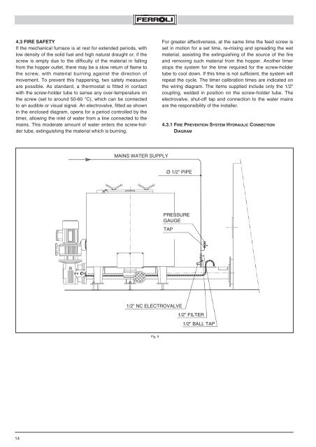
4.3 FIRE SAFETYIf the mechanical furnace is at rest for extended periods, withlow density of the solid fuel and high natural draught or, if thescrew is empty due to the difficulty of the material in fallingfrom the hopper outlet, there may be a slow return of flame tothe screw, with material burning against the direction ofmovement. To prevent this happening, two safety measuresare possible. As standard, a thermostat is fitted in contactwith the screw-holder tube to sense any over-temperature onthe screw (set to around 50-60 °C), which can be connectedto an audible or visual signal. An electrovalve, fitted as shownin the enclosed diagram, opens for a period controlled by thetimer, allowing the inlet of water from a line connected to themains. This moderate amount of water enters the screw-holdertube, extinguishing the material which is burning.For greater effectiveness, at the same time the feed screw isset in motion for a set time, re-mixing and spreading the wetmaterial, assisting the extinguishing of the source of the fireand removing such material from the hopper. Another timerstops the system for the time required for the screw-holdertube to cool down. If this time is not sufficient, the system willrepeat the cycle. The timer calibration times are indicated onthe wiring diagram. The items supplied include only the 1/2”coupling, welded in position on the screw-holder tube. Theelectrovalve, shut-off tap and connection to the water mainsare the responsibility of the installer.4.3.1 FIRE PREVENTION SYSTEM HYDRAULIC CONNECTIONDIAGRAMMAINS WATER SUPPLYØ 1/2” PIPEPRESSUREGAUGETAP1/2” NC ELECTROVALVE1/2” FILTER1/2” BALL TAPFig. 914
4.4 CONTINUOUS POWER MODULATIONAllows the heat input to be reduced continuously from 100%to 50% in the normal version, and up to 25% in the specialversion. The latter version uses motors with independentventilation. This allows the boiler to adjust over a wide fieldto the flexibility of the thermal load of the system withouthaving to shut-down, as this leads to sudden drops in temperaturein the combustion chamber, with consequent deteriorationof the emissions from the chimney. The temperatureor pressure controller acts on the separate inverters tovary the rotation speeds respectively of the fuel feed screw,the combustion air fans, as well as the cam shaft which drivesthe mobile grate. The system logic can be checked onthe main panel wiring diagram supplied. The system describedhere must only be calibrated by FERROLI techniciansresponsible for testing and inspection. The documentsenclosed with instruction booklet include the specific bookletfor the individual electrical control components.4.5 USE OF TRADITIONAL FUEL:DIESEL-FUEL OIL-GASAs well as solid granular fuel, burners can also be usedfor traditional fuels, such as DIESEL-FUEL OIL-GAS.There are two types of burners, in different positions andwith different functions.4.5.1 PILOT BURNERWith a limited output (200-400 kW), it has the function ofinitial ignition of the solid fuel. It is fitted in the correspondinghole on the side of the boiler, and features continuousventilation for cooling the burner nose when out-of-service.It is controlled according to the temperature in the combustionchamber, using a regulating instrument and thermocouple,and thus guarantees the ignition of the solid fuelpresent and prevents the accumulation of the latter in theabsence of combustion. It can not be used as an alternativeburner, but rather exclusively for igniting the solid fuel. Itsoperating time is typically brief. It is absolutely necessaryfor high-humidity materials (W≥60% dry weight).4.5.2 ALTERNATIVE BURNERThe boiler is specifically designed to burn solid fuels, yet itcan also be correctly used with a traditional burner assembly.Operation with this burner assembly must be considered asan ALTERNATIVE to operation with solid fuel, and NOTSIMULTANEOUS. The burner assembly is selected using theswitch on the electrical panel (WOOD or BURNER). The alternativeburner, during operation with solid fuel, must be movedback using the trolley, to avoid problems from the radiatedheat. The max allowable output is limited to 70% of theallowable limit for solid fuel. The hole is closed with an insulatedplug, hinged to the boiler body. The possible fuels are diesel,fuel oil and gas. For the latter, a quick-fit stub to move theburner assembly backwards is required in the final section ofthe supply tubing, in the other cases the final connectionshould be made using flexible tubing. Its operation is controlledby the same temperature or pressure regulator which controlsthe solid fuel burner assembly, and it can also be modulatedby steps or continuously. The boiler is fitted with automaticdraught regulation. This allows the automatic start-up ofthe boiler using a clock timer. The fitting of the latter to theboiler must be performed at our facilities.COMBUSTION CHAMBERFig. 101 ALTERNATIVE BURNER2 TROLLEY FOR MOVING THE ALTERNATIVE BURNER BACKWARDS15