BI Comb SGM.GB
BI Comb SGM.GB
BI Comb SGM.GB

Create successful ePaper yourself
Turn your PDF publications into a flip-book with our unique Google optimized e-Paper software.
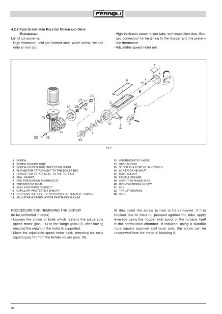
4.2.2 FEED SCREW WITH RELATIVE MOTOR AND DRIVEMECHANISMSList of components:- High-thickness, cold pre-formed steel worm-screw, weldedonto an iron bar.- High-thickness screw-holder tube, with inspection door, flangedconnection for fastening to the hopper and fire preventionthermostat.- Adjustable speed motor unitFig. 61 SCREW2 SCREW-HOLDER TUBE3 SCREW-HOLDER TUBE INSPECTION DOOR4 FLANGE FOR ATTACHMENT TO THE BOILER BED5 FLANGE FOR ATTACHMENT TO THE HOPPER6 SEAL GASKET7 FIRE PREVENTION THERMOSTAT8 THERMOSTAT BULB9 BULB FASTENING BRACKET10 CAPILLARY PROTECTIVE SHEATH11 COUPLING FOR FIRE PREVENTION ELECTROVALVE TU<strong>BI</strong>NG12 ADJUSTABLE SPEED MOTOR FASTENING FLANGE13 INTERMEDIATE FLANGE14 GEAR MOTOR15 SPEED ADJUSTMENT HANDWHEEL16 SCREW DRIVE SHAFT17 MALE SQUARE18 FEMALE SQUARE19 SHAFT FASTENING RING20 RING FASTENING SCREW21 KEY22 THRUST BEARING23 BUSHPROCEDURE FOR REMOVING THE SCREW(to be performed in order)- Loosen the crown of bolts which fastens the adjustablespeed motor (pos. 14) to the flange (pos.12), after havingensured the weight of the motor is supported.- Move the adjustable speed motor back, removing the malesquare (pos.17) from the female square (pos. 18).At this point the screw is free to be removed. If it isblocked due to material pressed against the tube, applyleverage using the hopper inlet spout or the furnace itselfin the combustion chamber. If required, using a suitablemale square spanner and lever arm, the screw can beunscrewed from the material blocking it.10