

9914V TAPE UNIT
9914V TAPE UNIT
9914V TAPE UNIT

You also want an ePaper? Increase the reach of your titles
YUMPU automatically turns print PDFs into web optimized ePapers that Google loves.
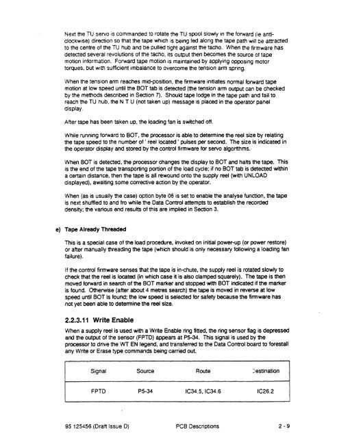
Next the TU servo is commanded to rotate the TU spool slowly in the forward (ie anticlockwise)direction so that the tape which is being fed along the tape path will be attractedto the centre of the TU hub and be pulled tight against the tacho. When the firmware hasdetected several revolutions of the tacho, its output then becomes the source of tapemotion information. Forward tape motion is maintained by applying oPPOSing motortorques, but with sufficient imbalance to overcome the tension arm spring.When the tension arm reaches mid-position, the firmware initiates normal forward tapemotion at low speed until the BOT tab is detected (the tension arm output can be checkedby the methods described in Section 7). Should tape lodge in the tape path and fail toreach the TU hub, the N T U (not taken up) message is placed in the operator paneldisplay.After tape has been taken up, the loading fan is switched off.While running forward to BOT, the processor is able to determine the reel size by relatingthe tape speed to the number of' reel located ' pulses per second. The size is indicated inthe operator display and stored by the control firmware for servo algorithms.When BOT is detected, the processor changes the display to BOT and halts the tape. Thisis the end of the tape transporting portion of the load cycle; if no BOT tab is detected withina certain distance, then the tape is all rewound onto the supply reel (with UNLOADdisplayed), awaiting some corrective action by the operator.When (as is usually the case) option byte 06 is set to enable the analyse function, the tapeis next shuffled to and fro while the Data Control attempts to establish the recordeddensity; the various end results of this are implied in Section 3.e) Tape Already ThreadedThis is a special case of the load procedure, invoked on initial power-up (or power restore)or after manually threading the tape (which should is only necessary following a loading fanfailure).If the control firmware senses that the tape is in-chute, the supply reel is rotated slowly tocheck that the reel is located (in which case it is also clamped squarely). The tape is thenmoved forward in search of the BOT marker and stopped with BOT indicated if the markeris found. Otherwise (after about 4 metres search) the tape is moved in reverse at lowspeed until BOT is found; the low speed is selected for safety because the firmware hasnot yet been able to determine the reel size.2.2.3.11 Write EnableWhen a supply reel is used with a Write Enable ring fitted, the ring sensor flag is depressedand the output of the sensor (FPTD) appears at P5-34. This signal is used by theprocessor to drive the WT EN legend, and transferred to the Data Control board to forestallany Write or Erase type commands being carried out.Signal Source Route JestinationFPTD P5-34 IC34.S,IC34.6 IC26.295 125456 (Draft Issue D) PCB Descriptions 2-9


