Chapter 16 nuts, bolts, screws and washers - ArchiCAD-Talk
Chapter 16 nuts, bolts, screws and washers - ArchiCAD-Talk
Chapter 16 nuts, bolts, screws and washers - ArchiCAD-Talk

Create successful ePaper yourself
Turn your PDF publications into a flip-book with our unique Google optimized e-Paper software.
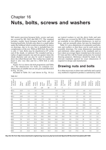
<strong>Chapter</strong> <strong>16</strong>Nuts, <strong>bolts</strong>, <strong>screws</strong> <strong>and</strong> <strong>washers</strong>ISO metric precision hexagon <strong>bolts</strong>, <strong>screws</strong> <strong>and</strong> <strong>nuts</strong>are covered by BS 3643 <strong>and</strong> ISO 272. The st<strong>and</strong>ardincludes washer faced hexagon head <strong>bolts</strong> <strong>and</strong> fullbearing head <strong>bolts</strong>. In both cases there is a small radiusunder the bolthead which would not normally be shownon drawings, due to its size, but is included here forcompleteness of the text. With an M36 bolt, the radiusis only 1.7 mm. Bolts may be chamfered at 45° at theend of the shank, or radiused. The rounded end has aradius of approximately one <strong>and</strong> one quarter times theshank diameter <strong>and</strong> can also be used if required todraw the rolled thread end. The washer face under thehead is also very thin <strong>and</strong> for a M36 bolt is only0.5 mm.Figure <strong>16</strong>.1(a) shows the bolt proportions <strong>and</strong> Table<strong>16</strong>.1 the dimensions for <strong>bolts</strong> in common use.Dimensions of suitable <strong>nuts</strong> are also given <strong>and</strong> illustratedin Fig. <strong>16</strong>.1(b).Included in Table <strong>16</strong>.1 <strong>and</strong> shown in Fig. <strong>16</strong>.1(c)are typical <strong>washers</strong> to suit the above <strong>bolts</strong> <strong>and</strong> <strong>nuts</strong><strong>and</strong> these are covered by BS 4320. St<strong>and</strong>ard <strong>washers</strong>are available in two different thicknesses, in steel orbrass, <strong>and</strong> are normally plain, but may be chamfered.Table <strong>16</strong>.1 gives dimensions of commonly used <strong>bolts</strong>,<strong>nuts</strong> <strong>and</strong> <strong>washers</strong> so that these can be used easily onassembly drawings. For some dimensions maximum<strong>and</strong> minimum values appear in the st<strong>and</strong>ards <strong>and</strong> wehave taken an average figure rounded up to the nearest0.5 mm <strong>and</strong> this will be found satisfactory for normaldrawing purposes. Reference should be made to therelevant st<strong>and</strong>ards quoted for exact dimensions ifrequired in design <strong>and</strong> manufacture.Buy this file from http://www.download-it.org/learning-resources.php?promoCode=&partnerID=&content=story&storyID=1046Table <strong>16</strong>.1Drawing <strong>nuts</strong> <strong>and</strong> <strong>bolts</strong>It is often necessary to draw <strong>nuts</strong> <strong>and</strong> <strong>bolts</strong> <strong>and</strong> a quickeasy method is required to produce a satisfactory result.Nominalsize threaddiameterThreadpitchMinordiameterof threadWidthacrosscornersWidthacrossflatsDiameterof washerfaceHeight ofbolt headThicknessof normalnutThicknessof thin nutWasherinsidediameterWasheroutsidediameterWasherthicknessForm AWasherthicknessForm BD A/C A/F Df H T tM1.6 0.35 1.1 3.5 3.0 1.0 1.25 1.7 4.0 0.3M2 0.4 1.4 4.5 4.0 1.5 1.5 2.2 5.0 0.3M2.5 0.45 1.9 5.5 5.0 1.75 2.0 2.7 6.5 0.5M3 0.5 2.3 6.0 5.5 5.0 2.0 2.25 3.2 7.0 0.5M4 0.7 3.0 8.0 7.0 6.5 2.75 3.0 4.3 9.0 0.8M5 0.8 3.9 9.0 8.0 7.5 3.5 4.0 5.3 10.0 1.0M6 1.0 4.7 11.5 10.0 9.0 4.0 5.0 6.4 12.5 1.6 0.8M8 1.25 6.4 15.0 13.0 12.0 5.5 6.5 5.0 8.4 17 1.6 1.0M10 1.5 8.1 19.5 17.0 <strong>16</strong>.0 7.0 8.0 6.0 10.5 21 2.0 1.25M12 1.75 9.7 21.5 19.0 18.0 8.0 10.0 7.0 13.0 24 2.5 1.6M<strong>16</strong> 2.0 13.5 27.0 24.0 23.0 10.0 13.0 8.0 17.0 30 3.0 2.0M20 2.5 <strong>16</strong>.7 34.0 30.0 29.0 13.0 <strong>16</strong>.0 9.0 21.0 37 3.0 2.0M24 3.0 20.0 41.5 36.0 34.5 15.0 19.0 10.0 25.0 44 4.0 2.5M30 3.5 25.5 52.0 46.0 44.5 19.0 24.0 12.0 31.0 56 4.0 2.5M36 4.0 31.0 62.5 55.0 53.5 23.0 29.0 14.0 37.0 66 5.0 3.0Buy this file from http://www.download-it.org/learning-resources.php?promoCode=&partnerID=&content=story&storyID=1046
Nuts, <strong>bolts</strong>, <strong>screws</strong> <strong>and</strong> <strong>washers</strong> 121A/CDDfHexagon headwasher facedA/FLengthHd1d2SSFull bearing head(c) Bright <strong>washers</strong>Form AForm BRolled thread end1 1 4 D(a) Hexagon head precision <strong>bolts</strong>Buy this file from http://www.download-it.org/learning-resources.php?promoCode=&partnerID=&content=story&storyID=1046A/CD30°ChamferoptionalA/FTt(b) Precision <strong>nuts</strong> <strong>and</strong> thin <strong>nuts</strong>Fig. <strong>16</strong>.1Proportions of <strong>bolts</strong>, <strong>nuts</strong> <strong>and</strong> <strong>washers</strong>. A/C means across corners. A/F means across flats.Nuts <strong>and</strong> <strong>bolts</strong> are not normally drawn on detaildrawings unless they are of a special type. They areshown on assembly drawings <strong>and</strong>, provided they arest<strong>and</strong>ard stock sizes, are called up in parts lists <strong>and</strong>schedules. A description of the head, the thread <strong>and</strong>the length being generally sufficient. Templates areavailable for drawing <strong>nuts</strong> <strong>and</strong> <strong>bolts</strong> <strong>and</strong> can berecommended for their time saving advantages.It is conventional drawing practice to show, as firstchoice, <strong>nuts</strong> <strong>and</strong> <strong>bolts</strong> in the across corners position ifa single view only is illustrated since this is instantlyrecognizable.DD0.8DWWApproximate constructionfor <strong>nuts</strong> <strong>and</strong> <strong>bolts</strong> (Figs<strong>16</strong>.2 <strong>and</strong> <strong>16</strong>.3)Stage 11 Draw a circle in the plan position, 2D in diameter,where D is equal to the thread size. In this examplelet us assume that the thread size is M20.2 Draw a hexagon inside the 40 mm diameter circle<strong>and</strong> inside the hexagon draw another circle tangentialto the hexagon on the six sides. This circle is theprojection of the chamfer which can be seen on thefront elevation.Fig. <strong>16</strong>.2 Stage 12D3 the nut thickness is 0.8D. Project the four cornersof the hexagon to the front elevation.4 Project three corners of the hexagon in the endelevation <strong>and</strong> note, that the width of the end elevationis given by dimension W.5 Line in the projected diameter of the chamfer circle<strong>and</strong> the base in the front elevation.6 As an approximation, draw a radius to show thechamfer on the front elevation. The radius shouldequal the thread size D.7 Add the female convention to the plan view.Buy this file from http://www.download-it.org/learning-resources.php?promoCode=&partnerID=&content=story&storyID=1046
122 Manual of Engineering DrawingISO metric socket cap <strong>screws</strong>Dimensions in Table <strong>16</strong>.2These <strong>screws</strong> are distinguished by square knurling onthe heads. Generally, the lengths of st<strong>and</strong>ard <strong>screws</strong>increase in increments of 5 mm <strong>and</strong> 10 mm, but theexact range should be checked from the manufacturerscatalogue.Fig. <strong>16</strong>.3 Stage 2ADStage 21 The projection of the curve on the chamfered facesof the hexagon that lie at an angle would produceellipses in the front elevation. In their place weusually show small circular arcs, their radii can befound by trial, but are approximately 0.25D.2 The end elevation of the nut has square corners <strong>and</strong>the projection of the corner which coincides withthe centre line terminates at the bottom of thechamfer curve.3 Complete the view by drawing circular arcs on thetwo chamfered faces. Find by trial, the radius of anarc which will touch the top of the nut <strong>and</strong> theprojection lines from the corner in the front elevation.Buy this file from http://www.download-it.org/learning-resources.php?promoCode=&partnerID=&content=story&storyID=1046Fig. <strong>16</strong>.4 ISO metric hexagon socket shoulder <strong>screws</strong>. Dimensions inTable <strong>16</strong>.3Reference to Fig. <strong>16</strong>.1a <strong>and</strong> b will show that theconstructions in Fig. <strong>16</strong>.2 <strong>and</strong> Fig. <strong>16</strong>.3 can be usedfor the bolthead <strong>and</strong> locknut where proportions forthickness can be approximated to 0.7D <strong>and</strong> 0.5D.For exact dimensions however, please refer to Table<strong>16</strong>.1.Socket head <strong>screws</strong> manufactured toBS EN ISO 4762 <strong>and</strong> BS 3643-2It is often required to draw these <strong>screws</strong> <strong>and</strong> althoughthe head type <strong>and</strong> the length are generally quoted inparts lists it is necessary to know the proportions ofthe head. Dimensions follow for each of the mostcommonly used <strong>screws</strong>.Before specifying <strong>screws</strong> it is advisable to consult amanufacturers list for availability. In the interest ofst<strong>and</strong>ardization <strong>and</strong> economy, designers are urged touse stock lengths wherever possible <strong>and</strong> st<strong>and</strong>ard lengthsof <strong>screws</strong> include the following; 3, 4, 5, 6, 8, 10, 12,<strong>16</strong>, 20, 25, 30, 35, 40, 45, 50, 55, 60, 65, 70, 75, 80,90, 100, 110, 120, 130, 140, 150, <strong>16</strong>0, 170, 180, 190,<strong>and</strong> 200 mm. If lengths over 200 mm are required,then increments of 20 mm are the preferred ISO lengths.It should be understood that not all diameters of screware available in the above lengths. For example, therange of lengths for an M3 screw lies between 5 <strong>and</strong>35 mm, for an M10 screw between 12 <strong>and</strong> 100 mm forone particular type of head. The same range will alsonot cover different types of head, hence the necessityto check stock lists.Table <strong>16</strong>.2KHThreadlengthScrew lengthNominal size D M3 M4 M5 M6 M8 M10 M12 M<strong>16</strong> M20Head diameter A 5.5 7 8.5 10 13 <strong>16</strong> 18 24 30Head depth H 3 4 5 6 8 10 12 <strong>16</strong> 20Key engagement K 1.3 2 2.7 3.3 4.3 5.5 6.6 8.8 10.7Socket size J 2.5 3 4 5 6 8 10 14 17ISO metric hexagon socket shoulder<strong>screws</strong>Dimensions in Table <strong>16</strong>.3Table <strong>16</strong>.3Nominal shoulder diameter B 6 8 10 12 <strong>16</strong>Head diameter A 10 13 <strong>16</strong> 18 24Head height H 4.5 5.5 7 8 10Socket size J 3 4 5 6 8Screw thread diameter D M5 M6 M8 M10 M12Nominal thread length Lt 9.75 11.25 13.25 <strong>16</strong>.4 18.4Key engagement K 2.45 3.3 4.15 4.92 6.62Fig. <strong>16</strong>.5 ISO metric hexagon socket button head <strong>screws</strong>. Dimensions inTable <strong>16</strong>.4Buy this file from http://www.download-it.org/learning-resources.php?promoCode=&partnerID=&content=story&storyID=1046AKHLLtDBJJ
<strong>Chapter</strong> extractTo buy the full chapter, <strong>and</strong> for copyrightinformation, click herehttp://www.download-it.org/learning-resources.php?promoCode=&partnerID=&content=story&storyID=1046The publisher detailed in the title page holds the copyright for this documentAll rights reserved. No part of this publication may be reproduced, stored in a retrieval system, or transmitted,in any form or by any means, electronic, mechanical, photocopying, recorded or otherwise, without the writtenpermission of Spenford IT Ltd who are licensed to reproduce this document by thepublisherAll requests should by sent in the first instance torights@download-it.orgPlease ensure you have book-marked our website.www.download-it.org