G:\Government\Document Files\Handbook ... - Granta Design
G:\Government\Document Files\Handbook ... - Granta Design
G:\Government\Document Files\Handbook ... - Granta Design

Create successful ePaper yourself
Turn your PDF publications into a flip-book with our unique Google optimized e-Paper software.
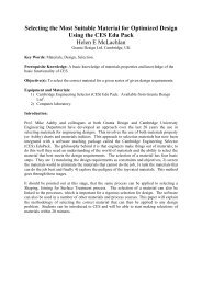
MIL-HDBK-5H1 December 1998 — 7075 is a high-strength Al-Zn-Mg-Cu alloy and is availablein a wide variety of product forms. It is also available in several types of tempers, the T6, T73, and T76type. The T6 temper has the highest strength but lowest toughness and resistance to stress-corrosioncracking. Since toughness decreases with a decrease in temperature, the T6 temper is not generallyrecommended for cryogenic applications. The T73 temper provides for much improved stress-corrosionresistance over T6 temper with a decrease in strength. The T76 temper provides for improved exfoliationresistance and limited stress-corrosion resistance over T6 temper with some decrease in strength. Refer toSection 3.1.2.3 for comments regarding the resistance of the alloy to stress-corrosion cracking and to Section3.1.3.4 for comments regarding the weldability of this alloy.The properties of extrusions should be based upon the thickness at the time of quenching prior tomachining. Selection of the mechanical properties based upon its final machined thickness may beunconservative; therefore, the thickness at the time of quenching to achieve properties is an important factorin the selection of the proper thickness column. For extrusions having sections with various thicknesses,consideration should be given to the properties as a function of thickness.Material specifications for 7075 aluminum alloy are presented in Table 3.7.4.0(a). Roomtemperaturemechanical and physical properties are shown in Tables 3.7.4.0(b 1 ) through (g 4 ). The effect oftemperature on the physical properties of this alloy is presented in Figure 3.7.4.0. SpecificationAMS 4044AMS 4045AMS 4078AMS-QQ-A-250/12, 24AMS-QQ-A-250/13, 25AMS 4049AMS 4122AMS 4123AMS 4124AMS 4186AMS 4187AMS-QQ-A-225/9AMS-QQ-A-200/11, 15AMS 4126AMS 4141AMS 4147MIL-A-22771QQ-A-367FormBare sheet and plateBare sheet and plateBare plateBare sheet and plateClad sheet and plateClad sheet and plateBar and rod, rolled or cold finishedBar and rod, rolled or cold finishedBar and rod, rolled or cold finishedBar and rod, rolled or cold finishedBar and rod, rolled or cold finishedRolled or drawn bar and rodExtruded bar, rod, and shapesForgingDie forgingForgingForgingForgingThe temper index for 7075 is as follows:Section Temper3.7.4.1 T6, T651, T652, T6510, T65113.7.4.2 T73, T7351, T7352, T73510, T735113-344
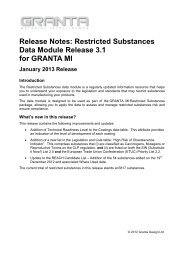
MIL-HDBK-5H1 December 1998 — Figures 3.7.4.1.1(a) and (b) permit calculationof residual tensile strengths for complex thermal exposure conditions. They are based upon the rateparameter T(C + log t), in which T is exposure temperature in degrees Rankine, t is exposure time in hoursand C is a constant evaluated for each material. These curves have been verified for use only within theranges of temperatures and exposure times covered in the figures. The following example illustrates theiruse.1 hour.Sample problem: Find F tu at 250F following a complex exposure of 300F, 8 hours plus 350F,1. Reduce given complex exposure by converting 350F exposure to equivalent exposure time at300F.*a. On the 350F single exposure temperature line find 350F, 1 hour.b. From this point move vertically to the 300F exposure temperature line and then readright, 12 hours exposure.c. Total equivalent exposure time at 300F is therefore 8 hours + 12 hours or 20 hours.2. Find F tu at 250F following 300F, 20 hours exposure:a. On the 300F exposure temperature line find 300F, 20 hours.b. From this point move vertically to the 250F test temperature curve and then read left,76 percent F tu .Solution: F tu is 76 percent of the original room temperature F tu . F ty is determined in like manner.F cy can be closely estimated by using the percent reduction factor determined for F ty . For specific data, seeReference 3.7.4.1.Stressed Thermal Exposure — Stress applied during sample and complex thermal exposure of 7075-T6 can have additional effect in reducing material strength. However, the effect becomes significant onlywhen exposure strains exceed 0.2 percent. For specific data, see Reference 3.7.4.1.Figures 3.7.4.1.1(c) through 3.7.4.1.5(b) present elevated temperature curves for variousmechanical properties. Figures 3.7.4.1.6(a) through (m) present tensile and compressive stress-strainand tangent-modulus curves at several temperatures. Figures 3.7.4.1.6(n) through (q) are full-range stressstraincurves for various products. Figures 3.7.4.1.8(a) through (h) provide room-temperature fatigue curvesfor T6 temper products. Fatigue-crack propagation data for sheet are presented in Figure 3.7.4.1.9.Graphical displays of the residual strength behavior of center-cracked tension panels are presented in Figure3.7.4.1.10(a) through (h). — Figures 3.7.4.2.6(a) through (d)present stress-strain and tangent-modulus curves for various products and tempers. Figures 3.7.4.2.6(e) and(f) are full-range stress-strain curves at room temperature for extrusion. Fatigue-crack-propagation data forplate are presented in Figures 3.7.4.2.9(a) through (c). Graphical displays of the residual strength behaviorof center-cracked tension panels are presented in Figures 3.7.4.2.10(a) and (b)._______________________* Choice of reference temperature is optional as long as it permits computation within the bounds of the figures.3-345
3-346 ! ! " Specification ........AMS 4045 and AMS-QQ-A-250/12Form .............. Sheet PlateTemper ............ T6 and T62 a T651Thickness, in. .......0.008-0.0110.012-0.0390.040-0.1250.126-0.2490.250-0.499Basis .............. S A B A B A B A B A B A B A B A B A B A BMechanical Properties:F tu , ksi:L ..............LT .............ST ............F ty , ksi:L ..............LT .............ST .............F cy , ksi:L ..............LT .............ST .............F su , ksi ...........F c bru , ksi:(e/D = 1.5) .......(e/D = 2.0) .......F c bry , ksi:(e/D = 1.5) .......(e/D = 2.0) .......e, percent (S-basis):LT .............E, 10 3 ksi .........E c , 10 3 ksi .........G, 10 3 ksi .........µ ................Physical Properties:, lb/in. 3 ..........C, K, and ...........74......63...........................57676...6967...6871...4611815210011777878...7270...7174...47121156105122...7878...7068...6972...47121156102119810.310.53.90.338080...7270...7174...48124160105122...7878...7169...7073...4712115610312188080...7371...7275...48124160106124...7778...6967...6771...431171459711497980...7169...6973...44120148100118...0.500-1.0007778...7068...6872...4411714510011777980...7270...7074...45120148103120...1.001-2.0007677...6967...6671...4411614310011767879...7169...6873...45119147103120...0.101See Figure 3.7.4.0a <strong>Design</strong> allowables were based upon data obtained from testing T6 temper sheet and from testing samples of sheet, supplied in the O or F temper, which were heat treated todemonstrate response to heat treatment by suppliers. Properties obtained by the user may be lower than those listed if the material has been formed or otherwise cold worked,particularly in the annealed temper, prior to solution heat treatment.b Caution: This specific alloy, temper, and product form exhibits poor stress-corrosion cracking resistance in this grain direction. It corresponds to an SCC resistance rating of D, asindicated in Table 3.1.2.3.1(a).c Bearing values are “dry pin” values per Section 1.4.7.1. See Table 3.1.2.1.1.757670 b666459 b62686744114141981132.001-2.5005777871 b686661 b64707045117145101117...10.310.63.90.33717266 b636156 b58656442108134941092.501-3.0005737468 b656358 b6067664311113797112...707165 b605854 b55616142107132891043.001-3.5005727367 b626055 b5764634311013593108...3.501-4.000666761 b565450 b5157573910112484983686963 b585652 b5259594110412887103...MIL-HDBK-5H1 December 1998
3-347 ! ! #$ Specification ........ AMS 4044 and AMS-QQ-A-250/12 AMS-QQ-A-250/12Form ..............PlateTemper ............T62 aThickness, in. ....... 0.250-0.499 0.500-1.000 1.001-2.000 2.001-2.500 2.501-3.000 3.001-3.500 3.501-4.000Basis .............. A B A B A B A B A B A B A BMechanical Properties:F tu , ksi:L ..............LT .............ST .............F ty , ksi:L ..............LT .............ST .............F cy , ksi:L ..............LT .............ST .............F su , ksi ...........F c bru , ksi:(e/D = 1.5) .......(e/D = 2.0) .......F c bry , ksi:(e/D = 1.5) .......(e/D = 2.0) .......e, percent (S-basis):LT .............E, 10 3 ksi .........E c , 10 3 ksi .........G, 10 3 ksi .........µ ................Physical Properties:, lb/in. 3 ..........C, K, and ........7478...6567...7070...431171459711497680...6769...7272...44120148100118...7478...6668...7071...4411714510011777680...6870...7273...45120148103120...7377...6467...6868...4411614310011767579...6569...7071...45119147103120...727670 b606459 b63656344114141981135747871 b626661 b65676545117145101117...10.310.63.90.330.101See Figure 3.7.4.0a <strong>Design</strong> allowables were based upon data obtained from testing samples of plate, supplied in O or F temper, which were heat treated to demonstrate response to heat treatment by suppliers.Properties obtained by the user may be lower than those listed if the material has been formed or otherwise cold worked, particularly in the annealed temper, prior to solution heat treatment.b Caution: This specific alloy, temper, and product form exhibits poor stress-corrosion cracking resistance in this grain direction. It corresponds to an SCC resistance rating of D, as indicated inTable 3.1.2.3.1(a).c Bearing values are “dry pin” values per Section 1.4.7.1. See Table 3.1.2.1.1.697266 b566156 b59616042108134941095717468 b586358 b6163624311113797112...687165 b525854 b55575742107132891045707367 b546055 b5759594311013593108...646761 b485450 b5052533910112484983666963 b495652 b5254554110412887103...MIL-HDBK-5H1 December 1998
3-348 ! ! " #$ Specification ....................... AMS-QQ-A-250/12 AMS 4078 and AMS-QQ-A-250/12Form ................................... Sheet PlateTemper ................................ T73 T7351Thickness, in. ......................0.040-0.2490.250-0.4990.500-1.0001.001-1.5001.501-2.0002.001-2.5002.501-3.0003.001-3.500 3.501-4.000Basis ................................... S S A B A B A B A B A B S SMechanical Properties:F tu , ksi:L ....................................LT ..................................ST ..................................F ty , ksi:L ....................................LT ..................................ST ..................................F cy , ksi:L ....................................LT ..................................ST ..................................F su , ksi .............................F brua , ksi:(e/D = 1.5) .....................(e/D = 2.0) .....................F brya , ksi:(e/D = 1.5) .....................(e/D = 2.0) .....................e, percent (S-basis):LT ..................................E, 10 3 ksi .........................E c , 10 3 ksi ........................G, 10 3 ksi .........................µ .......................................Physical Properties:, lb/in. 3 ...........................C, K, and ......................6767...5656...5558...3810513484102810.310.53.90.336869...5757...5659...38102131799576869...5757...5659...38103132a Bearing values are “dry pin” values per Section 1.4.7.1. See Table 3.1.2.1.1.b S-basis. The rounded T 99 value is as follows: F ty (LT) = 53 ksi.c S-basis. The rounded T 99 values are as follows: F tu (LT) = 65 ksi and F ty (LT) = 52 ksi.819777071...5959...5861...3910613683100...6768...5757...5659...38103132839966970...5959...5861...4010613686102...66676355555253575939102132829766869655757545559614010613685101...0.101See Figure 3.7.4.010.310.63.90.336566626768645555525357584010513583996 ...5252 b495054553910213179936364 c606566625353505155553910313281966 ...4949 c47475151381001287689626359494947475150389912776896606157484846455048379612476886MIL-HDBK-5H1 December 1998
MIL-HDBK-5H1 December 1998 ! " " ! "#$!Specification ...............AMS-QQ-A-250/24Form ...........................Sheet and plateTemper ....................... T76 T7651Thickness, in. ............. 0.063-0.249 0.250-0.499 0.500-1.000 1.001-1.500 1.501-2.000Basis ........................... S S S S SMechanical Properties:F tu , ksi:L ...........................LT ........................ST .........................F ty , ksi:L ...........................LT ........................ST .........................F cy , ksi:L ...........................LT ........................ST .........................F su , ksi .....................F brua , ksi:(e/D = 1.5) ...........(e/D = 2.0) ...........F brya , ksi:(e/D = 1.5) ...........(e/D = 2.0) ...........e, percent:LT ........................E, 10 3 ksi .................E c , 10 3 ksi ...............G, 10 3 ksi ................µ ...............................Physical Properties:, lb/in. 3 ..................C, K, and .............7273...6262...6165...4211214588102810.310.53.90.337172...6061...6064...40109141869987071...5960...5963...411081408699610.310.63.90.330.101See Figure 3.7.4.07071...5960...5963...421081408699570716559605659636343108140871005a Bearing values are “dry pin” values per Section 1.4.7.1. See Table 3.1.2.1.1.3-349
MIL-HDBK-5H1 December 1998 ! " " $! Specification .............. AMS 4049Form ...........................SheetTemper .......................T6Thickness, in. .............0.008-0.0110.012-0.0390.040-0.0620.063-0.1870.188-0.249Basis ........................... S A B A B A B A BMechanical Properties:F tu , ksi:L ............................LT .........................F ty , ksi:L ............................LT .........................F cy , ksi:L ............................LT .........................F su , ksi .....................F brub , ksi:(e/D = 1.5) ............(e/D = 2.0) ............F bryb , ksi:(e/D = 1.5) ............(e/D = 2.0) ............e, percent (S-basis):LT .........................E, 10 3 ksi:Primary .................Secondary .............E c , 10 3 ksi:Primary .................Secondary .............G, 10 3 ksi ................µ ...............................Physical Properties:, lb/in. 3 ..................C, K, and ................68...58.....................5717162606164421101429010587474656364674411514894110...10.39.510.59.7...0.33717163616265421101429110697575666465684511615096112...0.101...7474 a777769676871461191541001179 ...66646568441151489611210.39.810.510.0...0.337575666465684511615096112910.310.010.510.2...0.337777686667704611915499115...a S-Basis. The rounded T 99 value is 75 ksi.b Bearing values are “dry pin” values per Section 1.4.7.1.3-350
MIL-HDBK-5H1 December 1998 ! " " $! #$!Specification ..................................AMS-QQ-A-250/13Form .............................................SheetTemper ..........................................T6 and T62 aThickness, in. ...............................Basis ..............................................Mechanical Properties:F tu , ksi:L ..............................................LT ..........................................F ty , ksi:L ..............................................LT ............................................F cy , ksi:L .............................................LT ..........................................F su , ksi .......................................F b bru , ksi:(e/D = 1.5) ..............................(e/D = 2.0) ...............................F b bry , ksi:(e/D = 1.5) ..............................(e/D = 2.0) ..............................e, percent (S-basis):LT ...........................................E, 10 3 ksi:Primary ...................................Secondary ................................E c , 10 3 ksi:Primary ...................................Secondary ................................G, 10 3 ksi ...................................µ .................................................Physical Properties:, lb/in. 3 .....................................C, K, and ................................0.008-0.011 0.012-0.0390.040-0.0620.063-0.187 0.188-0.249S A B A B A B A B...68...58.....................57070 c6260616442108140901057747465636467441151489411010.39.5...10.59.7...0.33717163616265421101429110687575666465684511615096112...0.101...7373 d6563 e64674411314694110810.39.810.510.0...0.3377776967687146119154100117...7575666465684511615096112810.310.010.510.2...0.33a <strong>Design</strong> allowables were based upon data obtained from testing T6 temper sheet and from testing samples of sheet, suppliedin the O or F temper, which were heat treated to demonstrate response to heat treatment by suppliers. Properties obtainedmay be lower than those listed if the material has been formed or otherwise cold worked, particularly in the annealedtemper, prior to solution heat treatment.b Bearing values are “dry pin” values per Section 1.4.7.1.c S-Basis. The rounded T 99 value is 71 ksi.d S-Basis. The rounded T 99 value is 75 ksi.e S-Basis. The rounded T 99 value is 64 ksi.7777686667704611915499115...3-351
MIL-HDBK-5H1 December 1998 ! " " $! "#$!Specification ........Form ..............Temper ............AMS 4049 and AMS-QQ-A-250/13PlateT651Thickness, in. .......Basis ..............0.250-0.4990.500-1.000 a 1.001-2.000 a 2.001-2.500 a 2.501-3.000 a 3.001-3.500 a 3.501-4.000 aA B A B A B A B A B A B A BMechanical Properties:F tu , ksi:L ..............LT .............ST .............F ty , ksi:L ..............LT .............ST .............F cy , ksi:L ..............LT .............ST .............F su , ksi ............F bruc , ksi:(e/D = 1.5) .......(e/D = 2.0) .......F bryc , ksi:(e/D = 1.5) .......(e/D = 2.0) .......e, percent (S-basis):LT .............7475...6765...6569...421131399411197677...6967...6771...4311614397114...7576...6866...6670...421141419711377778...7068...6872...44117145100116...7475...6765...6469...421131399711367677...6967...6671...44116143100117...737470 b646259 b60656743111137951105757671 b666461 b6268704411414198113...697066 b615956 b57626441105130901055717268 b636158 b5864664210813494109...686965 b585654 b53596140104128861005707167 b605855 b5561634210713289104...646561 b545250 b495557389812180933666763 b565452 b515759391011248497...E, 10 3 ksi:Primary .........Secondary .......E c , 10 3 ksi:Primary .........Secondary .......G, 10 3 ksi .........µ ................10.310.010.610.3...0.33Physical Properties:, lb/in. 3 ..........C, K, and ........0.101...a These values, except in the ST direction, have been adjusted to represent the average properties across the whole section, includingthe 1-1/2 percent per side nominal cladding thickness.b Caution: This specific alloy, temper, and product form exhibits poor stress-corrosion cracking resistance in this grain direction. Itcorresponds to an SCC resistance rating of D, as indicated in Table 3.1.2.3.1(a).c Bearing values are “dry pin” values per Section 1.4.7.1. See Table 3.1.2.1.13-352
MIL-HDBK-5H1 December 1998 ! " " $! "#$!Specification .......Form .............Temper ...........AMS-QQ-A-250/13PlateT62 aThickness, in. ......Basis .............0.250-0.4990.500-1.000 b 1.001-2.000 b 2.001-2.500 b 2.501-3.000 b 3.001-3.500 b 3.501-4.000 bA B A B A B A B A B A B A BMechanical Properties:F tu , ksi:L .............LT ............ST ............F ty , ksi:L .............LT ............ST ............F cy , ksi:L .............LT ............ST ............F su , ksi ...........F brud , ksi:(e/D = 1.5) ......(e/D = 2.0) ......F bryd , ksi:(e/D = 1.5) ......(e/D = 2.0) ......e, percent (S-basis):LT ............7275...6365...6868...421131399411197377...6567...7070...4311614397114...7276...6466...6869...421141419711377478...6668...7071...44117145100116...7275...6265...6666...421131399711367377...6467...6868...44116143100117...717470 c586259 c62626343111137951105727671 c606461 c6365654411414198113...677066 c545956 c57596041105130901055697268 c566158 c5961624210813494109...666965 c505654 c53555740104128861005687167 c525855 c5557594210713289104...626561 c465250 c485053389812180933646763 c485452 c505255391011248497...E, 10 3 ksi:Primary ........Secondary ......E c , 10 3 ksi:Primary ........Secondary ......G, 10 3 ksi ........µ ...............10.310.010.610.33.90.33Physical Properties:, lb/in. 3 .........C, K, and .......0.101...a <strong>Design</strong> allowables were based upon data obtained from testing samples of plate, supplied in the O or F temper, which were heattreated to demonstrate response to heat treatment by suppliers. Properties obtained may be lower than those listed if the material hasbeen formed or otherwise cold worked, particularly in the annealed temper, prior to solution heat treatment.b These values, except in the ST direction, have been adjusted to represent the average properties across the whole section.c Caution: This specific alloy, temper, and product form exhibits poor stress-corrosion cracking resistance in this grain direction. Itcorresponds to an SCC resistance rating of D, as indicated in Table 3.1.2.3.1(a).d Bearing values are “dry pin” values per Section 1.4.7.1. See Table 3.1.2.1.1.3-353
MIL-HDBK-5H1 December 1998 ! " " $! % ! "#$!Specification .................AMS-QQ-A-250/25Form ..........................SheetPlateTemper .......................Thickness, in,. ................Basis .........................0.040-0.062T760.063-0.1870.188-0.2490.250-0.499T76510.500-1.000 aS S S S SMechanical Properties:F tu , ksi:L ..........................LT .........................F ty , ksi:L ..........................LT .........................F cy , ksi:L ..........................LT .........................F su , ksi ......................F brub , ksi:(e/D = 1.5) ................(e/D = 2.0) ................F bryb , ksi:(e/D = 1.5) ................(e/D = 2.0) ................e, percent:LT .........................6667565655594110313380928676857575660401041358194869705959586240107139849786869585857604010513387104868685757565940103131871036E, 10 3 ksi:Primary ...................Secondary .................E c , 10 3 ksi:Primary ...................Secondary .................G, 10 3 ksi ...................µ ............................10.39.810.510.0...0.3310.310.010.510.2...0.3310.310.010.610.3...0.33Physical Properties:, lb/in. 3 ....................C, K, and .................0.101...a These values have been adjusted to represent the average properties across the whole section, including the1-1/2 percent per side nominal cladding thickness.b Bearing values are “dry pin” values per Section 1.4.7.1. See Table 3.1.2.1.1.3-354
MIL-HDBK-5H1 December 1998 ! ! " " &' (!' ! ) (!' *' $!%+ !Specification ........Form...............AMS 4122, AMS 4123, AMS 4186, AMS 4187, and AMS-QQ-A-225/9Bar, rod, and shapes: rolled, drawn, or cold-finishedAMS 4124 andAMS-QQ-A-225/9Temper............. T6, T651, and T62 a T73 b,c or T7351 cThickness d , in. .......1.0001.001-2.0002.001-3.0003.001-4.0000.375-2.0002.001-3.000Basis............... A B A B A B A B S SMechanical Properties:F tu , ksi:L ...............LT..............F ty , ksi:L ...............LT..............F cy , ksi:L ...............LT..............F su , ksi ............F bru , ksi:(e/D = 1.5) .......(e/D = 2.0) .......F bry , ksi:(e/D = 1.5) .......(e/D = 2.0) .......e, percent (S-basis):L ...............7777 e6666 e64...46100123869277979 e6868 e66...471031268895...7775 e6666 e64...46100123869277977 e6868 e66...471031268895...7772 e6663 e64...46100123869277974 e6865 e66...471031268895...7769 e6660 e64...46100123869277971 e6862 e66...471031268895...68...56...54...4210113181100106865 e,f5652 e,f5455 f401011318110010E, 10 3 ksi..........E c , 10 3 ksi .........G, 10 3 ksi..........µ ................Physical Properties:, lb/in. 3 ..........C, K, and ........10.310.53.90.330.101See Figure 3.7.4.0a <strong>Design</strong> allowables were based upon data obtained from testing of T6 and T651 material and from samples of material, supplied in theO or F temper, which were heat treated to T62 temper to demonstrate response to heat treatment by suppliers.b <strong>Design</strong> allowables were based upon data obtained from testing T73 and T7351 temper material and from testing samples of material,supplied in the O or F temper, which were heat treated to T73 temper to demonstrate response to heat treatment by suppliers.c Bearing values are “dry pin” values per Section 1.4.7.1.d For rounds (rod) maximum diameter is 4 inches; for square bar, maximum size is 3½ inches; for rectangular bar, maximum thicknessis 3 inches with corresponding width of 6 inches; for rectangular bar less than 3 inches in thickness, maximum width is 10 inches.e Caution: This specific alloy, temper, and product form exhibits poor stress-corrosion cracking resistance in this grain direction. Itcorresponds to an SCC resistance rating of D, as indicated in Table 3.1.2.3.1(a).f ST grain direction.3-355
3-356 ! ! %Specification ............ AMS 4126, MIL-A-22771, and QQ-A-367 MIL-A-22771 and QQ-A-367Form ....................Die forgingTemper .................. T6 b T652Thickness e 1.001- 2.001- 3.001-1.001-2.001- 3.001-, in. ...........1.000 2.0003.000 4.000 1.0002.0003.000 4.000Basis .................... A B A B A B S A B A B A B SMechanical Properties:F tu , ksi:L .....................T a ....................F ty , ksi:L .....................T a ....................F cy , ksi:L .....................ST ...................F su , ksi .................F bruc , ksi:(e/D = 1.5) ...........(e/D = 2.0) ...........F bryc , ksi:(e/D = 1.5) ...........(e/D = 2.0) ...........e, percent (S-basis):L .....................T a ....................E, 10 3 ksi ..............E c , 10 3 ksi ..............G, 10 3 ksi ..............µ .......................Physical Properties:, lb/in. 3 ...............C, K, and ............7571 d78...67...706845109140871007 ...3 ...6461 d67644310513583967471 d77...66...69674410813886997 ...3 ...6361 d66644310413382947470 d76...65...68664310613684977 ...3 ...6360 d6663421041338294737062606563421021318193727571 d78...67...676945109140871007 ...3 ...6460 d646543105135839610.010.43.80.330.101See Figure 3.7.4.07471 d77...66...66684410813886997 ...3 ...6360 d63654310413382947470 d76...65...65674310613684977 ...3 ...6359 d636442104133829473706259626442102131819372MIL-HDBK-5H1 December 1998a T indicates any grain direction not within ±15 of being parallel to the forging flow lines. F cy (T) values are based upon short transverse (ST) test data.b When die forgings are machined before heat treatment, the mechanical properties are applicable provided the as-forged thickness is not greater than twice the thickness at time of heattreatment.c Bearing values are “dry pin” values per Section 1.4.7.1.d Specification value. T tensile properties are presented on an S basis only.e Thickness at the time of heat treatment.
MIL-HDBK-5H1 December 1998 ! " " +#$!AMS 4147,Specification ..........MIL-A-22771, andAMS 4141, MIL-A-22771, and QQ-A-367 AMS 4141 QQ-A-367Form ...................Die forgingTemper ................ T73 a,b T7352Thickness c 1.001- 2.001- 3.001- 4.001- 5.001-3.001-, in. .........1.000 2.000 3.000 4.000 5.000 6.000 3.000 4.000Basis ................... A B A B A B A B S S A B SMechanical Properties d :F tu , ksi:L ....................T e ...................F ty , ksi:L ....................T e ...................F cy , ksi:L ....................T e ...................F su , ksi ................F bruf , ksi:(e/D = 1.5) ..........(e/D = 2.0) ..........F bryf , ksi:(e/D = 1.5) ..........(e/D = 2.0) ..........e, percent (S-basis):L ....................T e ...................E, 10 3 ksi .............E c , 10 3 ksi ............G, 10 3 ksi .............µ .....................Physical Properties:, lb/in. 3 ..............C, K, and ...........6662 g5653 g5855399612578907371...61...6360421031358598......6662 g5653 g5855399612578907371...59...6159421031358394......6662 g5653 g5855399612578907369...59...6159411001318394......6461 g5552 g5754389312277887269...59...6158411001318394......10.010.43.80.336259 h5351 h.....................720.101See Figure 3.7.4.0a When die forgings are machined before heat treatment, the mechanical properties are applicable, provided the as-forgedthickness is not greater than twice the thickness at the time of heat treatment.b <strong>Design</strong> allowables were based upon data obtained from testing die forgings, heat treated by suppliers, and supplied in T73temper.c Thickness at the time of heat treatment.d Most of the A tensile values are higher than specification values; consequently, the A values shown are specification values.e T indicates any grain direction not within ±15 of being parallel to the forging flow lines. F cy (T) values are based upon shorttransverse (ST) test data.f Bearing values are “dry pin” values per Section 1.4.7.1.g Specification value. T tensile properties are presented on an S basis only.h T indicates any grain direction within ±15 of being perpendicular to the forging flow lines.6158 h5150 h.....................626662 g5651 g5655399612578907369...59...5960411001318394......64615349535338931227485723-357
MIL-HDBK-5H1 December 1998 ! " " ,! +Specification ........AMS 4126, MIL-A-22771, andQQ-A-367MIL-A-22771 and QQ-A-367Form ..............Hand forgingTemper ............ T6 a T6522.001- 3.001- 4.001- 5.001- 2.001- 3.001- 4.001- 5.001-Thickness, in. .......2.000 3.000 4.000 5.000 6.000 2.000 3.000 4.000 5.000 6.000Basis .............. S S S S S S S S S SMechanical Properties:F tu , ksi:L ...............LT ..............ST ..............F ty , ksi:L ...............LT ..............ST ..............F cy , ksi:L ...............LT ..............ST ..............F su , ksi ............F bruc , ksi:(e/D = 1.5) .......(e/D = 2.0) .......F bryc , ksi:(e/D = 1.5) .......(e/D = 2.0) .......e, percent:L ...............LT ..............ST ..............E, 10 3 ksi ..........E c , 10 3 ksi .........G, 10 3 ksi .........µ ................Physical Properties:, lb/in. 3 ..........C, K, and ........7473...6361...6361...44............94...737169 b615958 b6159...44............943717068 b605857 b.........43............832696866 b585656 b.........41............732686665 b565555 b.........41............63210.010.43.80.337473...6361...6361...44............94...0.101See Figure 3.7.4.0a When hand forgings are machined before heat treatment, the section thickness at time of heat treatment shall determine theminimum mechanical properties as long as the original (as-forged) thickness does not exceed the maximum thickness of the alloy asshown in the table. The maximum cross-sectional area of hand forgings is 256 sq in.b Caution: This specific alloy, temper, and product form exhibits poor stress-corrosion cracking resistance in this grain direction. Itcorresponds to an SCC resistance rating of D, as indicated in Table 3.1.2.3.1(a).c Bearing values are “dry pin” values per Section 1.4.7.1.737169 b615957 b6159...44............942717068 b605856 b.........43............831696866 b585655 b.........41............731686665 b565554 b.........41............6313-358
3-359 ! ! & %#$ Specification ............. MIL-A-22771 and QQ-A-367 AMS 4147, MIL-A-22771, and QQ-A-367Form ....................Hand forgingTemper .................. T73 a T7352Thickness, in. ............ 2.000 2.001-3.000 3.001-4.000 4.001-5.000 5.001-6.000 2.000 2.001-3.000 3.001-4.000 4.001-5.000 5.001-6.000Basis .................... S S S S S S S A B S SMechanical Properties:F tu, ksi:L .....................LT ...................ST ....................F ty, ksi:L .....................LT ...................ST ....................F cy, ksi:L .....................LT ...................ST ....................F su, ksi:L .....................LT ...................ST ....................F b bru, ksi:(e/D = 1.5) ............(e/D = 2.0) ............F b bry, ksi:(e/D = 1.5) ............(e/D = 2.0) ............e, percent (S-basis):L .....................LT ...................ST ....................E, 10 3 ksi ...............E c, 10 3 ksi ..............G, 10 3 ksi ...............µ .......................Physical Properties:, lb/in. 3 ................C, K, and .............6664...5654...5652...39..................74...6664615654525652...39..................743646360555351..............................732626158535150..............................732615957515049..............................6326664...5452...55555539363886120719074...10.210.43.80.330.101See Figure 3.7.4.0666461545250555555393638881207390743646360535048525253383737891187387732676663555351555556403839931237792.........626158514846494951373636861147183732615957494644464649363535841106880632MIL-HDBK-5H1 December 1998a When hand forgings are machined before heat treatment, the section thickness at time of heat treatment shall determine the minimum mechanical properties as long as the original(as-forged) thickness does not exceed the maximum thickness for the alloy as shown in the table. The maximum cross-sectional area of hand forgings is 256 sq. in.b Bearing values are “dry pin” values per Section 1.4.7.1.
3-360 ! ! '( Specification ............QQ-A-200/11Form .................. Extrusion (rod, bar, and shapes)Temper ................T6, T6510, T6511, and T62 aCross-Sectional Area, in. 2 .. 20 >20, 32 32Thickness, in. b ........... 0.249 0.250-0.499 0.500-0.749 0.750-1.499 1.500-2.999 3.000-4.499 4.500-5.000Basis .................. A B A B A B A B A B A B S A BMechanical Properties:F tu , ksi:L ...................LT .................ST ..................F ty , ksi:L ...................LT .................ST ..................F cy , ksi:L ...................LT .................ST ..................F su , ksi ...............F brud , ksi:(e/D = 1.5) ...........(e/D = 2.0) ...........F bryd , ksi:(e/D = 1.5) ...........(e/D = 2.0) ...........e, percent (S-basis):L ...................E, 10 3 ksi .............E c , 10 3 ksi .............G, 10 3 ksi .............µ ....................Physical Properties:, lb/in. 3 ..............C, K, and ............7875...7066...7072...411111409210878279...7470...7476...4411714897114...8178...7369...7374...431151469611378582...7772...7778...45121153101119...8177...7267...7273...431151459411178581...7671...7677...4512015299117...8175...7265...7271...431131449311078579...7669...7675...4511915198116...10.410.74.00.33817167 c726156 c726762421101418910670.101See Figure 3.7.4.0857571 c766559 c7671664411514894112...816767 c715655 c71626240106137841017846969 c745958 c7464644211014288105...786464 c705555 c70616139102132831006786363 c685252 c6857573810113179956816565 c715555 c7160604010513683100...MIL-HDBK-5H1 December 1998a <strong>Design</strong> allowables were based upon data obtained from testing T6, T6510, and T6511 temper extrusions and from testing samples of extrusion supplied in the O or F temper, whichwere heat treated to T62 temper to demonstrate response to heat treatment by suppliers. Properties obtained by the user may be lower than those listed if the material has beenformed or otherwise cold worked, particularly in the annealed temper, prior to solution heat treatment.b The mechanical properties are to be based upon the thickness at the time of quench.b Caution: This specific alloy, temper, and product form exhibits poor stress-corrosion cracking resistance in this grain direction. It corresponds to an SCC resistance rating of D, asindicated in Table 3.1.2.3.1(a).d Bearing values are “dry pin” values per Section 1.4.7.1.
3-361 ! ! '( #$ Specification ...............AMS-QQ-A-200/11Form ......................Extrusion (rod, bars, and shapes)Temper ...................T73 a , T73510, T73511Cross-Sectional Area, in. 2 20 25 20 >20, 32Thickness, in. b ........... 0.062-0.249 0.250-0.499 0.500-0.749 0.750-1.499 1.500-2.999 3.000-4.499 3.000-4.499Basis ..................... A B A B A B A B A B A B A BMechanical Properties:F tu , ksi:L .......................LT .....................F ty , ksi:L .......................LT .....................F cy , ksi:L .......................LT .....................F su , ksi ..................F brud , ksi:(e/D = 1.5) .............(e/D = 2.0) .............F bryd , ksi:(e/D = 1.5) .............(e/D = 2.0) .............e, percent (S-basis):L .......................E, 10 3 ksi ................E c , 10 3 ksi ...............G, 10 3 ksi ...............µ .........................Physical Properties:, lb/in. 3 ................C, K, and ..............68 c667270615961623910713786102758565859371011298297...70 c6874726360636340110141891058605760603810413384100...70 c6773706360636339108139881058605760603810313384100...70 c66736963586361391071388710386056605838103132839810.410.74.00.33...0.101See Figure 3.7.4.069 c627467655665594010613887103859 c51595437991287993...68 c58716162506253389913079947 ...57 c4657493795124728665 c56706060486051389812876917 ...a <strong>Design</strong> allowables were based upon data obtained from testing T7351X temper extrusions and from testing samples of extrusions supplied in the O or F temper, which were heattreated to T73 temper to demonstrate response to treatment by suppliers. Properties obtained by the user may be lower than those listed if the material has been formed or otherwisecold worked, particularly in the annealed temper.b The mechanical properties are to be based upon the thickness at the time of quench.c S-basis. See Table 3.7.4.0(g 3 ) for the rounded T 99 values.d Bearing values are “dry pin” values per Section 1.4.7.1.55 c44554735911197083MIL-HDBK-5H1 December 1998
MIL-HDBK-5H1 December 1998 (!! - .! ! / % ' 0' ! 00 12Cross-Sectional Area, in. 2 .. 20 25 20 >20, 32Thickness, inch ............. 0.062-0.249 0.250-1.499 1.500-2.999 3.000-4.499 3.000-4.499Mechanical Properties:F tu , ksi:L .........................F ty , ksi:L .........................69...71...7262695968573-362
MIL-HDBK-5H1 December 1998 ! " " 12#$!Specification ...............AMS-QQ-A-200/15Form ........................Extrusion (rod, bar, and shapes)Temper .....................T76, T76510, T76511Cross-Sectional Area, in. 2 .20Thickness, in. a ............. 0.062-0.249 0.250-0.499 0.500-0.749 0.750-1.000Basis ....................... A B S A B A BMechanical Properties:F tu , ksi:L .........................LT .......................F ty , ksi:L .........................LT .......................F cy , ksi:L .........................LT .......................F su , ksi ....................F brub , ksi:(e/D = 1.5) ...............(e/D = 2.0) ...............F bryb , ksi:(e/D = 1.5) ...............(e/D = 2.0) ...............e, percent (S-basis):L .........................E, 10 3 ksi ..................E c , 10 3 ksi .................G, 10 3 ksi .................µ ..........................Physical Properties:, lb/in. 3 ..................C, K, and ................71686157616238103131829877471656165664010713788104...757265616566411091398810477571656065654110913988104710.410.74.00.330.101See Figure 3.7.4.07673676267674211014190107...757065596564401091398810477671676167664111014190107...a The mechanical properties are to be based upon the thickness at the time of quench.b Bearing values are “dry pin” values per Section 1.4.7.1.3-363
MIL-HDBK-5H1 December 1998K, Btu/[(hr)(ft 2 )(F)/ft]1201101009080C, Btu/(lb)(F)0.60.50.40.30.2α - Between 70 F and indicated temperatureK - At indicated temperatureC - At indicated temperatureαK (T73XXX)K (T76XXX)K (T6XXX)C1514131211a, 10 -6 in./in./F700.1100 100 200 300 400 500 600 700 800Temperature, F+ 1 3-364
MIL-HDBK-5H1 December 1998+ 00 1 + %3' 30' 30' ! 300 ! 4) 5 6 ! 0+ 00 1 ! + %3' 30' 30' ! 300 ! 4) 5 6 ! 03-365
MIL-HDBK-5H1 December 19986WUHQJWK DW WHPSHUDWXUH([SRVXUH XS WR KU3HUFHQWDJH RI 5RRP 7HPSHUDWXUH ) WX×KU KU KU KU KU 7HPSHUDWXUH ƒ)+ 00 1 + %3' 30' 30' ! 300 !3-366
MIL-HDBK-5H1 December 19986WUHQJWK DW WHPSHUDWXUH([SRVXUH XS WR KU3HUFHQWDJH RI 5RRP 7HPSHUDWXUH ) W\×KU KU KU KU KU 7HPSHUDWXUH ƒ)+ 00! 1 ! + %3'30' 30' ! 300 !3-367
MIL-HDBK-5H1 December 19986WUHQJWK DW WHPSHUDWXUH([SRVXUH XS WR KU3HUFHQW )F\DW 5RRP 7HPSHUDWXUH×KU KU KU KU 7HPSHUDWXUH ƒ)+ 07 1 6 ! + %3' 30' 30' ! 300 !6WUHQJWK DW WHPSHUDWXUH([SRVXUH XS WR KU3HUFHQW ) VX DW 5RRP 7HPSHUDWXUH×KU KU KU KU 7HPSHUDWXUH ƒ)+ 07 1 + %3' 30' 30' ! 300 !3-368
MIL-HDBK-5H1 December 19986WUHQJWK DW WHPSHUDWXUH([SRVXUH XS WR KU3HUFHQW )EUXDW 5RRP 7HPSHUDWXUH×KU KU KU KU 7HPSHUDWXUH ƒ)+ 0 1 + %3' 30' 30' ! 300 !6WUHQJWK DW WHPSHUDWXUH([SRVXUH XS WR KU3HUFHQW )EU\DW 5RRP 7HPSHUDWXUH×KU KU KU KU 7HPSHUDWXUH ƒ)+ 0 1 ! + %3' 30' 30' ! 300 !3-369
MIL-HDBK-5H1 December 19980RGXOXV DW WHPSHUDWXUH7
MIL-HDBK-5H1 December 1998(ORQJDWLRQ DW WHPSHUDWXUH([SRVXUH XS WR KU3HUFHQW (ORJDWLRQ H KU×KU7
MIL-HDBK-5H1 December 1998100Long Transverse80Up to 100 -hr exposure(1000 -hr exposure)60Stress, ksi4020Ramberg - Osgoodn (Up to 100 -hr exp.) = 15n (1000 -hr exp.) = 11TYPICALThickness = 0.188 - 0.249 in.00 2 4 6 8 10 12Strain, 0.001 in./in.Compressive Tangent Modulus, 10 3 ksi+ 03 6 % ! 6 %! 6 ! %3 7+10080Long TransverseRamberg - Osgoodn (1/2 -hr exp.) = 18n (100 -hr exp.) = 12n (1000 -hr exp.) = 9.2601/2 -hr exposure100 -hr exposureTYPICALThickness = 0.188 - 0.249 in.Stress, ksi40201000 -hr exposure00 2 4 6 8 10 12Strain, 0.001 in./in.Compressive Tangent Modulus, 10 3 ksi+ 03 6 % ! 6 %! 6 ! %3 +3-372
MIL-HDBK-5H1 December 199850Long TransverseStress, ksi4030201/2 -hr exposure1/2 2 -hr exposure10 -hr exposureRamberg - Osgoodn (1/2 -hr exp.) = 6.3n (2 -hr exp.) = 14n (10 -hr exp.) = 7.5n (100 to 1000 -hr exp.) = 10TYPICALThickness = 0.188 - 0.249 in.10100 to 1000 -hr exposure00 2 4 6 8 10 12Strain, 0.001 in./in.Compressive Tangent Modulus, 10 3 ksi+ 03! 6 % ! 6 %! 6 ! %3 +25201/2 - hr exposureLong Transverse152 - hr exposureStress, ksi1010 - hr exposureRamberg - Osgoodn (1/2 -hr exp.) = 9.0n (2 -hr exp.) = 12n (10 -hr exp.) = 8.5TYPICAL5Thickness = 0.188 - 0.249 in.00 2 4 6 8 10 12Strain, 0.001 in./in.Compressive Tangent Modulus, 10 3 ksi+ 03 6 % ! 6 %! 6 ! %3 +3-373
MIL-HDBK-5H1 December 199825Long Transverse20Stress, ksi15101/2 - hr exposure10 - hr exposure100 - hr exposure1/2 - hr exposure10 - hr exposure100 - hr exposureRamberg - Osgoodn (1/2 -hr exp.) = 8.5n (10 -hr exp.) = 12n (100 -hr exp.) = 10n(1000 -hr exp.) = 17TYPICALThickness = 0.188 - 0.249 in.51000 - hr exposure00 2 4 6 8 10 12Strain, 0.001 in./in.Compressive Tangent Modulus, 10 3 ksi+ 03 6 % ! 6 %! 6 ! %3 3+10080L - tensionLT - tensionStress, ksi604020Ramberg - Osgoodn (L-tension) = 32n (LT-tension) = 17TYPICALThickness = 0.250 - 2.000 in.00 2 4 6 8 10 12Strain, 0.001 in./in.+ 03 % 6 %30 3-374
MIL-HDBK-5H1 December 199810080LT - compressionL - compressionStress, ksi604020Ramberg - Osgoodn (L-comp.) = 16n (LT-comp.) = 19TYPICALThickness = 0.250 - 2.000 in.00 2 4 6 8 10 12Strain, 0.001 in./in.Compressive Tangent Modulus, 10 3 ksi+ 03 6 % ! 6 %! 6 %30 10080L and LT - compressionL and LT - tensionStress, ksi604020Ramberg - Osgoodn(L-tension) = 22n(LT-tension) = 22n (L-comp.) = 25n (LT-comp.) = 22TYPICALL - compressionLT - compressionThickness = 0.250 - 2.000 in.00 2 4 6 8 10 12Strain, 0.001 in./in.Compressive Tangent Modulus, 10 3 ksi+ 03 ! 6 % ! 6%! 6 %37 3-375
MIL-HDBK-5H1 December 199810080L - tensionL - compressionStress, ksi604020Ramberg - Osgoodn (L-tension) = 50n (L-comp.) = 13TYPICALThickness ≤ 3.000 in.00 2 4 6 8 10 12Strain, 0.001 in./in.Compressive Tangent Modulus, 10 3 ksi+ 039 ! 6 % ! 6%! 6 %3 ! 30 !%' !' ! 10080L - tensionLT - tensionStress, ksi6040Ramberg - Osgoodn (L-tension) = 50n (LT-tension) = 22TYPICALThickness = 0.500 - 0.749 in.2000 2 4 6 8 10 12Strain, 0.001 in./in.+ 038 % 6 %30: 2 3-376
MIL-HDBK-5H1 December 1998100LT - compressionL - compressionLT - compressionL - compression8060Stress, ksi4020Ramberg - Osgoodn (L-comp.) = 26n (LT-comp.) = 27TYPICALThickness = 0.500 - 0.749 in.00 2 4 6 8 10 12Strain, 0.001 in./in.Compressive Tangent Modulus, 10 3 ksi+ 03 6 % ! 6 %! 6 %30: 2 100L - compressionLT - compressionL - tension80LT - compressionLT - tensionStress, ksi604020Ramberg - Osgoodn(L-tension) = 33n(LT-tension) = 22n (L-comp.) = 27n (LT-comp.) = 23TYPICALThickness = 0.250 - 1.499 in.00 2 4 6 8 10 12Strain, 0.001 in./in.Compressive Tangent Modulus, 10 3 ksi+ 03 ! 6 % ! 6%! 6 %37 2 3-377
MIL-HDBK-5H1 December 1998;/RQJLWXGLQDO/RQJ WUDQVYHUVH6WUHVV NVL7
MIL-HDBK-5H1 December 199890Longitudinal80X7060Stress, ksi5040302010TYPICAL00.00 0.02 0.04 0.06 0.08 0.10 0.12 0.14Strain, in./in.+ 03 % 6 %3 !30 ! !% ! 3-379
MIL-HDBK-5H1 December 1998;/RQJLWXGLQDO;/RQJ WUDQVYHUVH6WUHVV NVL7KLFNQHVV LQ7
MIL-HDBK-5H1 December 1998;/RQJLWXGLQDO;/RQJ WUDQVYHUVH6WUHVV NVL7KLFNQHVV LQ7
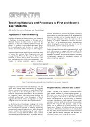
MIL-HDBK-5H1 December 1998+ 0< &% =4 6 ! %3 '6 ! ' ! !Correlative Information for Figure 3.7.4.1.8(a)Product Form: 3/4-inch diam. drawn rod, 1-1/4-inch diam. rolled rod, and 1 x 7-1/2-inch bar, extruded 1-1/4-inchbar and 1-1/4-inch rodProperties: TUS, ksi TYS, ksiSpecimen Details:Temp.,F82 72 RTSurface Condition: UnspecifiedReference: 3.7.4.1.8UnnotchedMinimum diameter 0.200-inchTest Parameters:Loading - AxialFrequency - 30 HzTemperature - RTEnvironment - AirNo. of Heats/Lots: 8Equivalent Stress Equation:Log N f = 18.21-7.73 log (S eq -10)S eq = S max (1-R) 0.62R 2 = 81%Sample Size = 130[Caution: The equivalent stress model mayprovide unrealistic life predictions for stressratios beyond those represented above.]3-382
MIL-HDBK-5H1 December 1998+ 0< &% =4 6 !' > ? 03' %3 ! ' ! !Correlative Information for Figure 3.7.4.1.8(b)Product Form: 1-1/8-inch diam. rolled barProperties: TUS, ksi TYS, ksiTemp.,F99.2 — RTSpecimen Details: Notched, K t = 1.6Notch-root-radius = 0.100Test section diameter (Net) =0.400 inchesGross diameter = 0.450 inch60 grooveSurface Condition: Polished to 10 micro-inchesReference: 3.2.1.1.8(b)Test Parameters:Loading - AxialFrequency - 60 HzTemperature - RTAtmosphere - AirNo. of Heats/Lots: 1Equivalent Stress Equation:Log N f = 8.28-2.62 log (S eq -15)S eq = S max (1-R) 0.53R 2 = 82%Sample Size = 34[Caution: The equivalent stress model mayprovide unrealistic life predictions for stressratios beyond those represented above.]3-383
MIL-HDBK-5H1 December 1998+ 0< &% =4 6 !' > ? ' %3 ! ' ! !Correlative Information for Figure 3.7.4.1.8(c)Product Form: 1-1/8-inch diam. rolled barProperties: TUS, ksi TYS, ksiTemp.,F96.5 — RTSpecimen Details: Notched, K t = 3.4Notch-root-radius = 0.010Test section diameter (Net)= 0.400 inchGross diameter = 0.450 inch60 grooveSurface Condition: Polished to 10 micro-inchesReference: 3.2.1.1.8(b)Test Parameters:Loading - AxialFrequency - 60 HzTemperature - RTAtmosphere - AirNo. of Heats/Lots: 1Equivalent Stress Equation:Log N f = 9.19-3.60 log (S eq -5)S eq = S max (1-R) 0.39R 2 = 87%Sample Size = 48[Caution: The equivalent stress model mayprovide unrealistic life predictions for stressratios beyond those represented above.]3-384
MIL-HDBK-5H1 December 1998+ 0
MIL-HDBK-5H1 December 1998+ 0< &% =4 6 !' > ? 0' %3 ' ! !Correlative Information for Figure 3.7.4.1.8(e)Product Form: Bare sheet, 0.090-inchProperties: TUS, ksi TYS, ksiTemp.,F82 76 RT(unnotched)87 — RT(notched)Specimen Details: Edge Notched3.000-inches gross width1.500-inches net width0.760-inch notch radius60 flank angleSurface Condition: ElectropolishedReference: 3.2.3.1.8(d)Test Parameters:Loading - AxialFrequency - 1100 to 1500 cpmTemperature - RTEnvironment - AirNo. of Heats/Lots: Not specifiedEquivalent Stress Equation:Log N f = 9.57-3.52 log (S eq -18.7)S eq = S max (1-R) 0.49Standard Error of Estimate = 0.41Standard Deviation in Life = 1.00R 2 = 83%Sample Size = 30[Caution: The equivalent stress model mayprovide unrealistic life predictions for stressratios beyond those represented above.]3-386
MIL-HDBK-5H1 December 1998+ 0< &% =4 6 !' > ? 7' %3 ' ! !Correlative Information for Figure 3.7.4.1.8(f)Product Form: Bare sheet, 0.090-inchProperties: TUS, ksi TYS, ksiSpecimen Details: NotchedTemp.,F82 76 RT(unnotched)88 — RT(notched)Notch Gross Net NotchType Width Width RadiusCenter 4.50 1.50 1.50Edge 2.25 1.50 0.3175Fillet 2.25 1.50 0.1736Surface Condition: ElectropolishedReferences: 3.2.3.1.8(b) and (f)Test Parameters:Loading - AxialFrequency - 1100 to 1500 cpmTemperature - RTEnvironment - AirNo. of Heats/Lots: Not specifiedEquivalent Stress Equation:Log N f = 7.50-2.46 log (S eq -18.6)S eq = S max (1-R) 0.54Standard Error of Estimate = 0.31Standard Deviation in Life = 0.85R 2 = 57%Sample Size = 112[Caution: The equivalent stress model mayprovide unrealistic life predictions for stressratios beyond those represented above.]3-387
MIL-HDBK-5H1 December 1998+ 0< &% =4 6 !' > ? ' %3 ' ! !Correlative Information for Figure 3.7.4.1.8(g)Product Form: Bare sheet, 0.090-inchProperties: TUS, ksi TYS, ksiSpecimen Details: NotchedTemp.,F82 76 RT(unnotched)82 — RT(notched)Notch Gross Net NotchType Width Width RadiusEdge 2.25 1.500 0.057Edge 4.10 1.500 0.070Fillet 2.25 1.500 0.0195Surface Condition: ElectropolishedReferences: 3.2.3.1.8(b), (f), (g), and (h)Test Parameters:Loading - AxialFrequency - 1100 to 1800 cpmTemperature - RTEnvironment - AirNo. of Heats/Lots: Not specifiedEquivalent Stress Equation:Log N f = 10.2-4.63 log (S eq -5.3)S eq = S max (1-R) 0.51Standard Error of Estimate = 0.51Standard Deviation in Life = 1.08R 2 = 78%Sample Size = 126[Caution: The equivalent stress model mayprovide unrealistic life predictions for stressratios beyond those represented above.]3-388
MIL-HDBK-5H1 December 1998+ 0< &% =4 6 !' > ? ' %3 ' ! !Correlative Information for Figure 3.7.4.1.8(h)Product Form: Bare sheet, 0.090-inchProperties: TUS, ksi TYS, ksiTemp.,F82 76 RT(unnotched)77 — RT(notched)Specimen Details: Edge Notched2.25-inch gross width1.500-inch net width0.3125-inch notch radiusSurface Condition: ElectropolishedReference: 3.2.3.1.8(c)Test Parameters:Loading - AxialFrequency - 1100 to 1500 cpmTemperature - RTEnvironment - AirNo. of Heats/Lots: Not specifiedEquivalent Stress Equation:Log N f = 7.51-2.92 log (S eq -6.7)S eq = S max (1-R) 0.58Standard Error of Estimate = 0.23Standard Deviation in Life = 1.08R 2 = 95%Sample Size = 37[Caution: The equivalent stress model mayprovide unrealistic life predictions for stressratios beyond those represented above.]3-389
MIL-HDBK-5H1 December 1998+ 0@ +%8% ! @% % 8 %3 * 8 A( 0@ BSpecimen Thickness: 0.090 inch Environment: Lab airSpecimen Width: 1-1/2 - 12 inches Temperature: RTSpecimen Type: M(T) Orientation: L-T3-390
MIL-HDBK-5H1 December 1998+ 00 (! 6 3% % 8 %3 $8 %C A(0703B+ 00 (! 6 3% % 8 %3 $8 %C A(0703! ! B3-391
MIL-HDBK-5H1 December 1998+ 00 (! 6 @% ! 0% % 8 %3 $8 C%A( 0703' ' ! 0@B+ 00! (! 6 0% % 8 %3 $8 C% A(0703B3-392
MIL-HDBK-5H1 December 1998+ 00 (! 6 0% % 8 %3 $8 C% A(0703B+ 00 (! 6 % % 8 %3 ! $8 C% A(0703 ! 00B3-393
MIL-HDBK-5H1 December 1998+ 00 (! 6
MIL-HDBK-5H1 December 199810080L - compressionL - compressionLT - compressionL - tensionLT - tension60LT - compressionStress, ksi4020Ramberg - Osgoodn(L-tension) = 48n(LT-tension) = 30n (L-comp.) = 27n (LT-comp.) = 26TYPICALThickness = 0.250 - 1.499 in.00 2 4 6 8 10 12Strain, 0.001 in./in.Compressive Tangent Modulus, 10 3 ksi+ 73 ! 6 % ! 6%! 6 % 2 10080L and LT - compressionL and LT - compressionLT - tensionL - tension60Stress, ksi4020Ramberg - Osgoodn(L-tension) = 34n(LT-tension) = 25n (L-comp.) = 28n (LT-comp.) = 28TYPICALThickness = 0.500 - 0.749 in.00 2 4 6 8 10 12Strain, 0.001 in./in.Compressive Tangent Modulus, 10 3 ksi+ 73 ! 6 % ! 6%! 6 % 0: 2 3-395
MIL-HDBK-5H1 December 199810080L - tensionStress, ksi604020LT - tensionST - tensionRamberg - Osgoodn (L-tension) = 15n (LT-tension) = 17n (ST-tension) = 12TYPICALThickness = 3.001 - 5.000 in.00 2 4 6 8 10 12Strain, 0.001 in./in.+ 73 % 6 % 7 ! 1008060ST - compressionLT - compressionL - compressionST - compressionLT - compressionL - compressionStress, ksi4020Ramberg - Osgoodn (L-comp.) = 15n (LT-comp.) = 13n (ST-comp.) = 15TYPICALThickness = 3.001 - 5.000 in.00 2 4 6 8 10 12Strain, 0.001 in./in.Compressive Tangent Modulus, 10 3 ksi+ 73! 6 % ! 6 %! 6 % 7 ! 3-396
MIL-HDBK-5H1 December 1998908070Long transverseXLongitudinalx60Stress, ksi5040302010Thickness: 0.500 - 0.749 in.TYPICAL00.00 0.02 0.04 0.06 0.08 0.10 0.12 0.14Strain, in./in.+ 73 % 6 % 0: 2 3-397
MIL-HDBK-5H1 December 1998/RQJLWXGLQDO/RQJ WUDQVYHUVH[ [6WUHVV NVL7
MIL-HDBK-5H1 December 1998+ 7@ +%8% ! 7% % 8' % 0 * 8 A( 70@! ! 7@BSpecimen Thickness: 0.250-inch Environment: 50% R.H.Specimen Width: 8, 16, 36-inches Temperature: RTSpecimen Type: M(T) Orientation: L-T3-399
MIL-HDBK-5H1 December 1998+ 7@ +%8% ! % % 8' % 0 * 8 A( 07039 ! 7@ BSpecimen Thickness: 0.475 to 0.500-inch Environment: 50-95% R.H.Specimen Width: 6, 8, 16, 36-inches Temperature: RTSpecimen Type: M(T) Orientation: L-T3-400
MIL-HDBK-5H1 December 1998+ 7@ +%8% ! 0% % 8' % 0 * 8 A( 70@! ! 7@ ! BSpecimen Thickness: 1.00-inch Environment: 50% R.H.Specimen Width: 6, 8, 16, 36-inches Temperature: RTSpecimen Type: M(T), C(T) Orientation: L-T3-401
MIL-HDBK-5H1 December 1998+ 70 (! 6 3% % 8 % 0 $8 C% A(0703B+ 70 (! 6 0% % 8 % 0 $8 C% A(07039B3-402