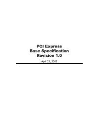
Development *** THIS IS NOT A FINAL DRAFT *** <strong>SFF</strong>-<strong>8449</strong> Rev 1.1FIXEDSIDEFREESIDEFREESIDEFIXEDSIDE<strong>MANAGEMENT</strong><strong>INTERFACE</strong>POWER<strong>INTERFACE</strong><strong>MANAGEMENT</strong><strong>INTERFACE</strong>POWER<strong>INTERFACE</strong>HIGH SPEEDSERIAL <strong>INTERFACE</strong>Figure 5 Management Interface Scope5. High Density (<strong>HD</strong>) Connector Physical Layer Interface5.1 Signal AssignmentThe fixed and free-side <strong>HD</strong> connector interface supports four bi-directional highspeed differential serial links and a management interface. Table 1 identifies allsignals of the connector interface.Signal Pin Mating DefinitionLevelReserved A1 Second Reserved for future useIntL A2 Second Management interface interrupt signalGND A3 First Signal groundRX1+ A4 Third Fixed side receiver channel 1 non-inverting inputRX1- A5 Third Fixed side receiver channel 1 inverting inputGND A6 First Signal groundRX3+ A7 Third Fixed side receiver channel 3 non-inverting inputRX3- A8 Third Fixed side receiver channel 3 inverting inputGND A9 First Signal groundVact B1 Second Free side power input for non-management interfacecircuitryModPrsL B2 Second Free side active low present outputGND B3 First Signal groundRX0+ B4 Third Fixed side receiver channel 0 non-inverting inputRX0- B5 Third Fixed side receiver channel 0 inverting inputGND B6 First Signal ground<strong>HD</strong> Management Interface Page 10
Development *** THIS IS NOT A FINAL DRAFT *** <strong>SFF</strong>-<strong>8449</strong> Rev 1.1RX2+RX2-GNDSCLSDAGNDTX1+TX1-GNDTX3+TX3-GNDVactVmanGNDTX0+TX0-GNDTX2+TX2-GNDB7 Third Fixed side receiver channel 2 non-inverting inputB8 Third Fixed side receiver channel 2 inverting inputB9 First Signal groundC1 Second Management interface serial clockC2 Second Management interface serial data outputC3 First Signal groundC4 Third Fixed side transmitter channel 1 non-inverting outputC5 Third Fixed side transmitter channel 1 inverting outputC6 First Signal groundC7 Third Fixed side transmitter channel 3 non-inverting outputC8 Third Fixed side transmitter channel 3 inverting outputC9 First Signal groundD1 Second Free side power input for non-management interfacecircuitryD2 Second Free side power input for management interfacecircuitryD3 First Signal groundD4 Third Fixed side transmitter channel 0 non-inverting outputD5 Third Fixed side transmitter channel 0 inverting outputD6 First Signal groundD7 Third Fixed side transmitter channel 2 non-inverting outputD8 Third Fixed side transmitter channel 2 inverting outputD9 First Signal groundTable 1 <strong>HD</strong> Connector Physical Layer Interface5.2 High Speed Serial InterfacePins A4, A5, A7, A8, B4, B5, B7, B8, C4, C5, C7, C8, D4, D5, D7 and D8 are outsidethe scope of this document.5.3 Management InterfacePins A1, A2, B1, B2, C1, C2, D1 and D2 comprise the management interface. Note thatGND pins A3, A6, A9, B3, B6, B9, C3, C6, C9, D3, D6 and D9 are required for reliablemanagement interface operation although they are not classified as part of themanagement interface.5.3.1 Signal Definition5.3.1.1 VmanThe fixed-side shall provide power for the free-side device management interfacecircuitry on the Vman signal. Removal of power from the Vman signal shall disablethe free-side management circuitry. Upon restoration of power to the Vman signal,the management interface shall perform all necessary power up tasks. The <strong>SFF</strong>-<strong>8449</strong>management interface does not include a dedicated reset signal. To reset the freesidemanagement interface circuitry, the fixed side may cycle power off and on. Seetable TBD for Initialization Time requirements, signal levels and other resetcircuitry parameters.5.3.1.2 VactTo support active cable designs, the fixed side shall provide power to both Vactpins in addition to the Vman pin. Designs not supporting active cables terminateVact as specified in table TBD. Timing requirements are detailed in table TBD.<strong>HD</strong> Management Interface Page 11


![[MS-DFSRH]: DFS Replication Helper Protocol Specification](https://img.yumpu.com/51326226/1/190x245/ms-dfsrh-dfs-replication-helper-protocol-specification.jpg?quality=85)
![[MS-VDS]: Virtual Disk Service (VDS) Protocol Specification](https://img.yumpu.com/50743814/1/190x245/ms-vds-virtual-disk-service-vds-protocol-specification.jpg?quality=85)
![[MS-GPSI]: Group Policy: Software Installation Protocol Extension](https://img.yumpu.com/50703911/1/190x245/ms-gpsi-group-policy-software-installation-protocol-extension.jpg?quality=85)

![[MS-GPPREF]: Group Policy: Preferences Extension Data Structure](https://img.yumpu.com/50206932/1/190x245/ms-gppref-group-policy-preferences-extension-data-structure.jpg?quality=85)