from GAMMATRON "DATUM" - The MESSUI Place
from GAMMATRON "DATUM" - The MESSUI Place
from GAMMATRON "DATUM" - The MESSUI Place

You also want an ePaper? Increase the reach of your titles
YUMPU automatically turns print PDFs into web optimized ePapers that Google loves.
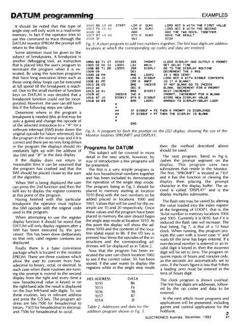
DATUM prammingEXAMPLESIt should be noted that this type ofsingle step will only work in a read/writememory. In fact if the operator tries touse this command to trace through theDATUM monitor EPROM the prompt willreturn to the display.Some attention must be given to thesubject of breakpoints. A breakpoint isanother debugging tool, an instructionthat is placed into the user's program toterminate the program when it is executed.By using this function programsthat have long execution times such asthose using delay loops can be executedat full speed till the breakpoint is reached.Due to the small number of functionkeys on DATUM is was decided that abreakpoint function could not be incorporated.However, the user can still havethis if the following steps are taken.Determine where in the program abreakpoint is needed (this at first may beonly a guess) and change the opcode ofof the selected instruction to a "3F" for asoftware interrupt (SWI) (note down theoriginal opcode for future reference). Runthe program in the normal way and if it iscorrect and there are no very long delaysin the program the displays should immediatelylight up with the address ofthe SWI and "3F" in the data display.If the display does not return inreasonable time it can be assumed thatthe program has crashed and that theSWI should be placed closer to the startof the algorithm.When SWI is being displayed the usercan pres5 the 2nd function and then theM/R key to display the register contentsat this point of the program.Having finished with this particularbreakpoint the operator must replacethe SWI opcode with the original codeused in the program.When attempting to use the registerdisplay function it should be noted thatDATUM will only display registers after aSWI has been executed by the processor.This has been done deliberatelyso that only valid register contents aredisplayed.Finally there is a base conversionpackage which is located in the monitorEPROM. <strong>The</strong>re are three routines whichallow the user to convert <strong>from</strong> hexadecimalto binary, octal, or decimal. Ineach case when these routines are runningthe prompt is moved to the seconddisplay <strong>from</strong> the right and every time anew hexadecimal value is keyed in onthe right=hand side the result is displayedon the four left-hand side digits. To runthese routines, key in relevant addressand press the G/S key. <strong>The</strong> program addressare hex 7500 for hexadecimal tobinary, 7503 for hexadecimal to decimal,and 7506 for hexadecimal to octal.1010 B6 10 001013 F6 10 011016 lB1017 B7 10 02101A 3F1000 BD 71 071003 CE 00 101006 BD 71 DD1009 09100A 26 FA100C 96 10100E 81 FF1010 26 031012 4A1013 20 011015 4C1016 97 101018 20 E9START LDA ALDA BABASTA ASWISTARTLOOP1LOOP2INCDISSTORIT*****SUM1SUMSSUMSJSR PROMPTLDXJSR DISPLYDEXBNE LOOP2LDA A DISBUFCMP A #$FFBNE INCDISDEC ABRA STORITINC ASTA A DISBUFBRA LOOP1Programs for DATUMThis subject will be covered in moredetail in the next article, however, byway of introduction a few programs willbe presented.<strong>The</strong> first is a very simple program toadd two hexadecimal numbers togetherand has been included to demonstratethe operation of the single step mode.<strong>The</strong> program listing in Fig. 5 should beplaced in memory starting at location1010 (hex) with the two numbers to beadded placed in locations 1000 and1001. Values that will be used for this exampleare 10 and 20 respectively. Oncethese values and the program have beenplaced in memory the user should beginthe single step mode at location 1010. Atthis point the display will show the address1010 and the contents of the location(data) equal to B6. If the I/D key ispressed four times the opcodes of the instructionsand the corresponding addresseswill be displayed as in Table 2.Now that the program has been executedthe user can check location 1002to see if the correct value, 30, has beenstored. If the user wants to display theregisters while in the single step modeHEX ADDRESS DATA1010 B61013 F61016 1B1017 B7101A3FTable 2: Addresses and data for theaddition program shown in Fig. 5.LOAD ACC A WITH THE FIRST VALUELOAD ACC B WITH THE SECONDADD THE TWO ACCS. TOGETHERSAVE THE RESULTSTOPFig. 5: A short program to add two numbers together. <strong>The</strong> first four digits are addresslocations at which the corresponding op codes and data are entered.CLEAR DISPLAY AND OUTPUT A PROMPTSET DELAY TIMEGO TO THE DISPLAY ROUTINEDECREMENT THE X REGIS X REG ZERO?LOAD ACC A WITH DISBUF CONTENTSIS IT A BLANK?IF NOT BLANK GO TO INCDISBLANK, DECREMENT FOR A PROMPTSKIP INCREMENTPROMPT, INCREMENT FOR A BLANKSTORE NEW DISPLAY VALUEBRANCH TO DISPLAY/DELAY LOOPIF DISBUF = FE THEN A PROMPT IS DISPLAYEDIF DISBUF = FF THEN THE DISPLAY IS BLANKENDFig. 6: A program to flash the prompt on the LED display, showing the use of theMonitor routines SPROMPT and DISPLAY.then the method described aboveshould be used.<strong>The</strong> next program, listed in Fig. 6,lashes the prompt segment on thedisplay. This program uses twosubroutines that reside in the Monitor.<strong>The</strong> first, "SPROMPT" is located at 7107and it has the function of clearing thedisplay then placing the promptcharacter in the display buffer. <strong>The</strong> secondis called "DISPLAY" and is thedisplay multiplex subroutine.<strong>The</strong> flash rate may be varied by alteringthe value loaded into the index registerat the beginning of LOOP1, that is, the16-bit number in memory locations 1004and 1005. Currently it is 0010, but if it isreduced the flash rate will increase. <strong>The</strong>final listing, Fig. 7, is that of a 12 hourclock. When running, this program promptsthe user with a lower case "t" andwaits till the time has be.en entered. If anon-decimal number is entered or an invaliddigit is keyed in, then the incorrectdigit will be set to zero. <strong>The</strong> program requiresinputs of hours and minutes only,as the seconds are automatically set tozero. If the hours figure is less that 9 thena leading zero must be entered in thetens of hours digit.<strong>The</strong> clock program is shown overleaf.<strong>The</strong> first four digits are addresses, followedby the op codes and data to beentered.In the next article more programs andapplications will be presented, includinggames and control applications for thehobbyist.ELECTRONICS Australia, December, 982 97