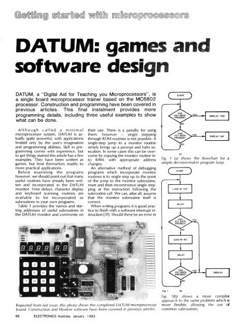
DATUM: games ansofare designDATUM, a "Digital Aid for Teaching you Microprocessors", isa single board microprocessor trainer based on the MC6802processor. Construction and programming have been covered inprevious articles. This final instalment provides moreprogramming details, including three useful examples to showwhat can be done.Although called a minimalmicroprocessor system, DATUM is actually quite powerful, with applicationslimited only by the user's imaginationand programming abilities. Skill in programmingcomes with experience, butto get things started this article has a fewexamples. <strong>The</strong>y have been written asgames, but lend themselves readily tomore practical applications.Before examining the programshowever, we should point out that manyuseful routines have already been writtenand incorporated in the DATUMmonitor. Time delays, character displayand keyboard scanning routines areavailable to be incorporated assubroutines in your own programs.Table 1 provides the names and startingaddresses of useful subroutines inthe DATUM monitor and comments ontheir use. <strong>The</strong>re is a penalty for usingthem, however — single steppingthrough ROM routines is not possible. Asingle-step jump to a monitor routinesimply brings up a prompt and halts execution.In some cases this can be overcomeby copying the monitor routine intoRAM, with appropriate addresschanges.An alternative method of debuggingprograms which incorporate monitorroutines is to single step up to the pointof the jump to the monitor subroutine,reset and then recommence single steppingat the instruction' following thesubroutine call. We can, after all, assumethat the monitor subroutine itself iscorrect.When writing programs it is good practiceto finish with a software interrupt instruction(3F). Should there be an error inFig. 1 (a) shows the flowchart for asimple decision-maker program loop.STARTLOAD IN 'YES'DELAYLOAD IN 'NO'DELAYRepeated <strong>from</strong> last issue, this photo shows the completed DATUM microprocessorboard. Construction and Monitor software have been covered in previous articles.Fig. 1(b)Fig. 1(b) shows a more complexapproach to the same problem which ismore flexible, allowing the use ofcommon subroutines.86 ELECTRONICS Australia, January, 1983
the program then this instruction maystop the program running into highermemory locations and overwriting yourprogram. With these remarks out of theway we can discuss the exampleprograms.A decision makerThis simple decision maker programconsists of a loop that is interrupted bydepressing any of the hex keys. <strong>The</strong>flowchart of Fig. 1(a) shows that the programconsists of two decisions,represented by the diamond boxes.Depending on the exact time a key isdepressed, the answer is either "yes" or"no". Fig. 1(b) shows a more complex approachwhich has a number of advantages.By loading in the word to bedisplayed before a decision has to bemade, a common display subroutine canbe used. <strong>The</strong> program could be organisedso that the delay and decision blockscan be shared, but since these aresubroutines within the monitor that wewill call upon there is little point in doingthis.By introducing delay blocks we canweight the "yes-no" decisions dependingon the relative length of each delay. Inthis program we will make them equal togive a 50:50 chance for the answers tobe "yes" or "no". Finally, both flowdiagrams can readily be extended tobecome higher order decision makers,with other words like "stop", "danger"being displayed.<strong>The</strong> next question is how the flow chartof Fig. 1(b) is converted into an actualprogram. Each box represents a smallprogram, or "module" which must bewritten. We will consider each functionin turn.Firstly we have to load the displayregister with hex numbers that providethe appropriate characters for ourmessage when they are decoded by thedisplay drivers. From the monitor listing(supplied with DATUM kits) it can beseen that a range of characters isavailable in a "Display look-up table" atlines 77A0 to 77C1.Also <strong>from</strong> the monitor listing we cansee that memory locations 0010 to 0015are the six display register locations.Whatever is loaded into memory location0010 is displayed on the first sevensegment display, with the contents ofmemory location 0011 displayed as thesecond digit and so on (all addresses arein hexadecimal).Loading of the word "no" is performedin the same way except that only the firstthree digits have to be changed, sincethe last three are already blanked.To display the word "yes" we mustload location 0010 with 48, the hex codefor "y", location 0011 with 06 ("E"), andlocation 0012 with 42 ("S"). Locations0013 to 0015 are loaded with hex 7F,which is the code for a blank. <strong>The</strong> firstProgram listing Decision maker0010 DISBUF EQU $10 DISPLAY BUFFER MEMORY71DD DISPLY EQU $71DD DISPLAY REFRESH7177 MPXK EQU $7177 KEYBOARD SCAN71D2 TIMLP EQU $71D2 10MS TIME DELAY1000 ORG $1000SET UP TO DISPLAY 'YES'1000 CE 00 10 YESSET LDX #DISBUF POINT TO DISBUF1003 86 48 LDA A #$48 LOAD ACC A WITH A 'Y'1005 A7 00 STA A 0,X PUT IT IN THE 1ST DIGIT1007 86 06 LDA A #6 LOAD ACC A WITH AN 'E'1009 A7 01 STA A 1,X PUT IT IN THE 2ND DIGIT100B 86 42 LDA A #$42 LOAD ACC A WITH AN 'S'100D A7 02 STA A 2,X PUT IT IN THE 3RD DIGIT100F 86 7F LDA A #$71 LOAD ACC A WITH ABLANK1011 A7 03 STA A 3,X1013 A7 04 STA A 4,X1015 A7 05 STA A 5,X1017 BD 71 D2 JSR TIMLP WAIT FOR 10 MSHAS A KEY BEEN PRESSED?101A BD 71 77 JSR MPXK SCAN KEYBOARD101D 26 19 BNE OUTPUTSET UP DISPLAY FOR 'NO'101F CE 00 10 LDX #DISBUF POINT TO DISBUF1022 86 3A LDA A #$3A LOAD ACC A WITH AN 'N'1024 A7 00 STA A 0,X PUT IT IN THE 1ST DIGIT1026 86 01 LDA A #1 LOAD ACC A WITH AN '0'1028 A7 01 STA A 1,X PUT IT IN THE 2ND DIGIT102A 86 7F LDA A #$71 LOAD ACC A WITH ABLANK102C A7 02 STA A 2,X102E BD 71 D2 JSR TIMLP WAIT FOR 10 MSHAS A KEY BEEN PRESSED?1031 BD 71 77 JSR MPXK SCAN KEYBOARD1034 26 02 BNE OUTPUT1036 20 C8 BRA YESSET SET UP FOR 'YES' AGAINOUTPUT THE DECISION AND FREEZE THE DISPLAY1038 86 80 OUTPUT LDA A #$80 SET DISPLAY FREEZE TIME103A B7 10 48 STA A TEMP SAVE IT103D BD 71 DD OUT1 J. DISPLY REFRESH THE DISPLAY1040 7A 10 48 DEC TEMP1043 26 F8 BNE OUT1 IS IT FINISHED?1045 20 B9 BRA YESSET STAR AGAIN1047 3F SWI1048 TEMP RMB 1 FREEZE TIMEEND<strong>The</strong> first five lines of this listing are information only. <strong>The</strong> program code startsat address 1000 and each line contains two or three bytes of code which areloaded into successive addresses. <strong>The</strong> program ends at address 1047, withlocation 1048 used as temporary storage.part of the decision maker program inlisting 1 uses the index register to addressthe display registers one by one.A short time delay is required by thesecond module of the program, and thiscan be most easily achieved by using thetiming subroutines in the monitor. Ajump to TIMLP at address 71D2 will providea 10ms delay. Larger delays can begenerated by using additional loops tocall TIMLP as many times as required.Alternatively by using another timingsubroutine XTIMLP at memory location71D7, we can provide a delay equal to 8multiplied by the value in the X register,in microseconds.Testing whether or not a key has beendepressed can be done by using themonitor subroutine MPXK at address7177. At the end of this subroutine anon-zero number is loaded into accumulatorB if a key has been pressedwhile the value of the key is in accumulatorA.In this case we are not interested in theparticular key, but simply whether or nota key has been depressed. Thus, if accumulatorB has zero contents, no keyhas been depressed and we must continueon in the loop. However, if thecontents of accumulator B are non-zero,a key has been depressed and the appropriate"decision" must be displayed.Listing 1 thus shows a jump to test if akey has been depressed (to location101A) and the subsequent statements totest whether the contents of accumulatorB are zero or not.ELECTRONICS Australia, January, 1983 87