Open PDF - Harworth Heating Ltd
Open PDF - Harworth Heating Ltd
Open PDF - Harworth Heating Ltd

You also want an ePaper? Increase the reach of your titles
YUMPU automatically turns print PDFs into web optimized ePapers that Google loves.
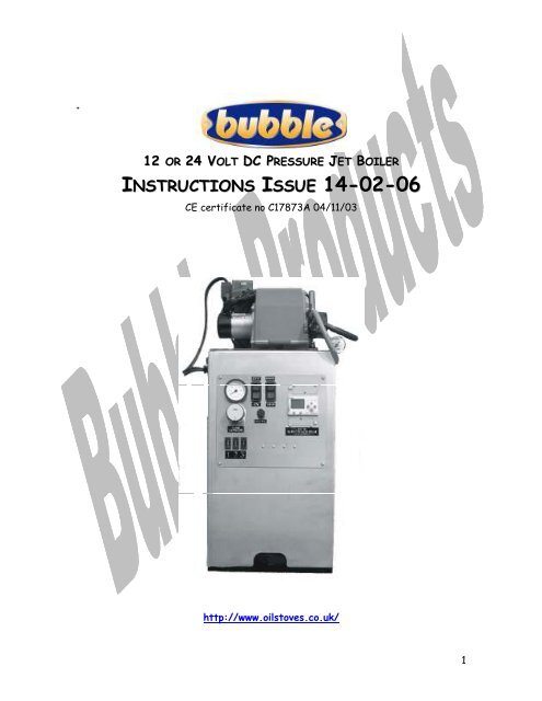
+12 OR 24 VOLT DC PRESSURE JET BOILERINSTRUCTIONS ISSUE 14-02-06CE certificate no C17873A 04/11/03http://www.oilstoves.co.uk/1
Index1 Introduction _________________________________________________41.1 Built in water circulating pumps. ______________________________51.3 Integral Digital control system Millennium Two. ___________________51.4 Summer – Winter switch. ___________________________________51.5 Oil filter. _______________________________________________51.6 Oil isolation valve. ________________________________________51.7 24-VOLT DC Version of Industry standard pressure jet oil burner. ____51.8 Simple Room stat._________________________________________51.8 Simple Adjustable Cylinder stat. ______________________________51.9 Applicable Standards.______________________________________51.10 Dimensions______________________________________________62 Optional Extras _____________________________________________62.1 12/24 volt digital time clock._________________________________62.2 High recovery hot water cylinder. _____________________________72.3 Flue Systems.____________________________________________72.5 Pressure Vessel for NON-POTABLE water. ______________________72.8 Pressurisation kit for potable water. ___________________________72.9 12 to 24V dc power supply. __________________________________72.10 230 Volt a.c. to 24 Volt d.c. 10 amp power supply.__________________72.11 Spare memory cartridge. _____________________________________73 Modes of Operation ___________________________________________83.1 Manual On Off Switch _____________________________________83.2 Remote Time Clock. _______________________________________84 Installation __________________________________________________94.1 Clearances for servicing the boiler. ____________________________94.2 Location. ______________________________________________ 104.3 Plumbing. ______________________________________________ 104.4 Water Treatment________________________________________ 104.4 Hot water. _____________________________________________ 124.5 Power Connection.________________________________________ 124.6 Controls Connection. ______________________________________ 124.7 Schematic Electrical External controls.__________________________ 134.8 Oil supply. _____________________________________________ 134.8.1 Schematic Oil Layout ___________________________________ 142
4.9 Fire Prevention. _________________________________________ 144.10 Flueing.______________________________________________ 144.10.1 Vertical _______________________________________________ 154.10.2 Horizontal _____________________________________________ 164.11 Ventilation. ___________________________________________ 165 Time Control ________________________________________________175a Internal Controller __________________________________________175a.1 Setting the Current Time and Date. _________________________ 175a.2. Summer/Winter Switch. _________________________________ 195a.3 Turning The Millenium two controller into its run mode. _____________206 Commissioning The Boiler ______________________________________206.1 Firing up. ______________________________________________206.2 Vent air from the boiler and heating system. ____________________ 216.3 Commission the heating pressure system. ______________________ 216.4 Check the heating system. _________________________________ 216.5 The effect of TRV’s. _____________________________________ 216.6 Check hot water system, expansion vessel and pressure release devices. 216.7 Checking The Flue Gas Emissions And Temperature. _______________227 Routine Maintenance __________________________________________237.1 Introduction. ___________________________________________237.2 Removing and cleaning the burner.____________________________237.3 To remove and clean the flame tube. __________________________257.5 To remove examine and adjust the electrode. ___________________257.6 To remove and clean the photocell. ___________________________257.7 To check the fuel pump pressure. ____________________________267.8 To set the burner combustion. ______________________________267.9 Removing the baffle systems and cleaning the boiler. ______________277.10 Checking the oil line.______________________________________287.10a Changing The Brushes in the Burner Motor. _____________________287.11 Checking the firevalve. ____________________________________287.12 Checking the flue system. __________________________________287.13 Checking the provision of ventilation. _________________________288 Fault Finding and electrical diagrams _____________________________288.2 Internal Hard Wiring Layout________________________________308-3 12 Volt DC to 24 Volt DC Converter Wiring Diagram ________________ 319 Fill in the Warranty Form _____________________________________3210 Running Costs ______________________________________________323
10.1 Fuel Consumption.________________________________________3210.2 Electrical Consumption.____________________________________321 INTRODUCTIONMOST OF THE CRITICAL INFORMATION RELATIVE TO FITTING THEBOILER WILL BE FOUND IN SECTION 4.THE EXTERNAL WIRING CONNECTIONS ARE IN 8.3The Bubble P.J. is a purpose designed, heavy-duty, automatic oil fired boiler whichwill power heating systems up to 15 kW.It is suitable for applications where mains 230v ac electrical power is not availableor unreliable.It can be fitted to a 24v DC supply and it will draw 8 amps for the first 20seconds of operation and thereafter 4 amps whilst the burner is running.For 12v DC systems it can be powered by two Mastervolt 12 to 24 volt DC-DC 8amp converters Pt No 8660 (www.mastervolt.com) on this system it will drawhigher current in the order of 9 amps running and a higher surge at start.When used with the 12-v DC converter there must be at least 150 amp hr batterypower available, preferably 2 batteries in parallel.The boiler is powered by a down firing pressure jet oil burner and space above theappliance must be provided for service access and vertical removal of the burner,to achieve this the flue system must be so designed as to allow it to slip up fromthe boiler socket to allow the rear access plate of the boiler to be lifted off.Instrumentation is mounted on a removable front panel and comprises of-:1. On-Off switch2. Summer Winter switch.3. Boiler Temperature control thermostat.4. Safety Thermostat.5. Three Fuses to protect the integral pumps and burner.6. Boiler Temperature gauge.7. Millenium ii Micro Processor.8. Boiler Water Pressure Gauge.4
The boiler can be used to heat up hot water cylinders, central heating systems, orboth simultaneously.The water jacket is insulated with 15mm insulation and is housed in a panelled case.Automatic time control is provided by a remote, programmable time clock.Room stat functions are controlled by a separate, room stat.The operating functions of the boiler are automatically controlled by a built indigital control system.The automatic control system operates via two integral 24 volt dc water circulatingpumps, respectively turned on or off by the action of the cylinder or roomtemperature control thermostats.The boiler has been specially developed to make installation, servicing, faultfindingand operation simple and reliable.The 12 and 24VDC versions are supplied complete with -:1.1 BUILT IN WATER CIRCULATING PUMPS.1.3 INTEGRAL DIGITAL CONTROL SYSTEM MILLENNIUM TWO.1.4 SUMMER – WINTER SWITCH.1.5 OIL FILTER.1.6 OIL ISOLATION VALVE.1.7 24-VOLT DC VERSION OF INDUSTRY STANDARD PRESSURE JET OIL BURNER.1.8 SIMPLE ROOM STAT.1.8 SIMPLE ADJUSTABLE CYLINDER STAT.1.9 APPLICABLE STANDARDS.1. Flexible oil hoses must comply with the requirements of ISO 7840 Fire resistantfuel hoses.5
1.10 DIMENSIONS2 OPTIONAL EXTRAS2.1 12/24 VOLT DIGITAL TIME CLOCK.The digital time clock is a seven-day programmable time clock with a storagecapacity of 10 on and 10 off programmed instructions.ExampleOn at 06.00 and Off at 09.00 and On at 16.00 and Off at 22.00.Repeated for seven days would use 2 on times up and 2 off times up, leaving afurther 16 programmed instructions available.If a further on and off time were to be programmed in at say On at 12.00 and Offat 14.00, repeated for the seven days, then one more programmed instructionwould have been used making a total usage of three on times and three off timesper day, leaving a further 14 programmed instructions available.The programmer has a built in rechargeable battery, which automatically keepsitself charged as soon as input power is available.6
If the input voltage is turned off the battery will keep the clock powered up for aminimum of 150 hours.The battery powers the clock mechanism and the input voltage powers the relay.The clock has-:1.Push button advance and manual override facilities and comes complete withprogramming instructions.2. Simple Summer time to Winter time switching.3. 12 or 24 hr display2.2 HIGH RECOVERY HOT WATER CYLINDER.High recovery, unvented hot water cylinders equipped with safety vales andexpansion vessels to prevent the wastage of domestic hot water.The order code for the cylinders is 77-01-640 (section 5) Marine Spares PriceList.2.3 FLUE SYSTEMS.The boiler is fitted with a vertical top flue take off.Single skin flue systems are available for conventional flue applications.(The flue pipe must be fitted so as to allow vertical movement of 150mm min tofacilitate boiler servicing.)Flue systems are in section 02 of the Marine Spares Price List2.5 PRESSURE VESSEL FOR NON-POTABLE WATER.The Pressure vessel for non-potable water is supplied as an optional extra.Installation is quick, easy and compact.See section 05 of the Marine Spares Price List.2.8 PRESSURISATION KIT FOR POTABLE WATER.2.9 12 TO 24V DC POWER SUPPLY.2.10 230 VOLT A.C. TO 24 VOLT D.C. 10 AMP POWER SUPPLY.2.11 SPARE MEMORY CARTRIDGE.The spare memory EPROM is used to restore a corrupted program in theMillennium 11 processor.7
The controller can be seen in FIG 1. In the top right hand corner of the Millennium11 processor is a blank plug, remove the plug and insert the memory plug pushing itin until it is flush with the front face of the controller.When the EPROM is fitted-:1. Press the RED ESCAPE button.2. Curser down to memory cartridge.3. Press Green Button for OK.4. Press OK to stop program prompt.5. Curser down to RESTORE and OK on that.6.You will be asked to confirm OK on that.7.You will then see the message-restoring program followed by restorationcomplete message, OK on that.8. OK on RUN.9. OK on Init and Run.10. Press the RED ESCAPE button.The controller program is now restored and the boiler should be operated asnormal.3 MODES OF OPERATIONThe boiler can be activated via3.1 MANUAL ON OFF SWITCHIn this mode it is assumed that the boiler is located in a readily accessible locationand the user can turn the boiler on and off as required.3.2 REMOTE TIME CLOCK.A remote programmable time clock as detailed in the optional extras list, can beset to control the on – off times as required.When energy is supplied to boiler, the built in automatic, digital control systemtakes over and controls all functions of the boiler as listed below.1. The Burner2. The Central heating water circulating pump3. The Hot water cylinder water circulating pump.When the burner is turned on, two integral circulating pumps are turned on or offby the action of the cylinder or room temperature control thermostats.8
As per normal convention hot water production is given priority, which meansthat the hot water pump will run first.By the action of the summer – winter switch, the central heating pump can beturned permanently off during the summer period and then the boiler will only heatthe hot water cylinder.4 INSTALLATIONABREVIATED KEY INFORMATION.4.1 CLEARANCES FOR SERVICING THE BOILER.The flue must be able to lift out and clear of the flue socket by about 20mmto allow the rear cover plate to be removed for servicing.To achieve this the flue pipe will have to be secured to the deck flange to allow itto self-support when the sliding lower part of the flue is lifted up. (Seeillustration is section 2-3)_2.The burner will need to be lifted at least 80mm to allow for easy removalduring servicing or setting up.3. If the burner is fitted in an enclosed compartment, high and low level ventilationwill be required.4. The oil supply to the fuel pump on the burner is a two pipe system, make surethat the connection is made as per the direction indicators on the burner fuelpump and fuel supply filter.5. Oil can be fed to the pump through the filter and then directly back to the fueltank. For easy servicing make sure that there are isolation valves fitted on thesupply and return to prevent the spillage of diesel when the oil feed pipes aredisconnected.6. The filter can be fitted in a convenient position near to the appliance, make upinterconnecting extension pipes as required, and make sure that the filter can beeasily serviced and exchanged.7. Make sure that the oil feed pipes will have sufficient movement to allow theburner to be lifted up and out of the boiler for servicing.8. The front control panel of the boiler hinges open to allow service access to thewiring and pumps.Do not place any pipework or other items across the front panel of the boiler.The water content of the boiler is 16 litres9
4.2 LOCATION.Make sure that the boiler is fitted with adequate space above it to allow foreasy service access.If the boiler is fitted under a worktop then the section of worktop above itmust be easily removable to allow the service engineer easy access.The burner will need to be lifted at least 80mm to allow it to be removedfrom the top of the boiler.The boiler is serviced from the top and access from the top is required toremove the internal baffle system.The burner can be fitted with either a conventional or balanced flue system.If the burner is fitted in an enclosed compartment, high and low level ventilationwill be required.4.3 PLUMBING.One of the main design features of the boiler is the ease with which the boiler canbe plumbed in.The boiler is supplied with three fittings for the installer to connect into.The top one is a 15mm flow to the hot water cylinder or calorifier.The next one down is a similar 15mm flow to the central heating circuit.The bottom one is a 15mm connection to take the combined return from both thehot water and heating circuits.Each of the two top outlets has its own pump and to prevent counter circulationeach pump is fitted with a 15mm non-return valve.Make sure that the plumbing pipe work has adequate means of venting trapped air.4.4 WATER TREATMENTDo not fit the boiler in to old established systems without they have beendrained down and fully flushed out with a suitable flushing agent.The following products are recommended for use with this pump:Flushing:Additive:http://www.fernox.comFernox DS-40Fernox Alphi-11After flushing rinse the system thoroughly and apply a suitable water treatmentwhich should contain suitable antifreeze and anti rusting agent.10
This is most important as the built in circulating pumps have magnetic drivemechanisms, which will become fouled up with iron oxide deposits circulatingaround the heating system.Failed pumps stained with brown oxide deposits or powder will not be replacedunder warranty.Schematic Plumbing Layout.The installer runs:1) A supply and return to and from the cylinder or calorifier.2) A supply and return to the heating systemBoth supply pipes have their own connection to the boiler and both returns aretwinned up and connected into one return pipe close to the boiler.When tightening up the boiler unions to the boiler, drop the front panel of theboiler to allow access to the non-return valves and hold the valve bodies witha suitable spanner to make sure that they do not rotate during the tighteningprocess.11
Pipe work must be adequately supported so as not to transmit any undue strainback on to the boiler unions.All pipe work (Primary and Secondary) must be free of air traps, where thereis a potential for air traps to occur, automatic air vents must be fitted.The boiler can be fitted to a pressurised circuit of max pressure 2.5 bar.4.4 HOT WATER.The calorifier must be of a suitable design with a high recovery coil fitted.We can supply calorifiers as required.4.5 POWER CONNECTION.Power is connected to the boiler 24 V D.C. (2.5mm diameter conductor) using aThree pin Male Connector.If the appliance is going to be used with the 12 to 24 dc converters see wiringdiagram in sec 8.34.6 CONTROLS CONNECTION.The boiler has an automatic, built in, pre programmed control system, which allowsit to heat up the hot water in the cylinder or calorifier first, and thenautomatically switch over to heat the central heating system.This is achieved by the turning on, or off, of separate water circulating pumps foreach individual circuit.The installer fits a clip on cylinder thermostat to the hot water cylinder and aroom thermostat in the saloon area, both of these stats are connected back to thepre wired and pre marked connections on the side of the boiler casing.Both stats are wired-:Closed circuit is calling.<strong>Open</strong> circuit is satisfied.The Cylinder stat is a 2 pin Female on the appliance.The Room stat is a 2 pin Male on the appliance.Both stats are supplied with the boiler.Before the boiler can run the built in Millennium 2 controller has to be turned intoits run mode as detailed in section 5A. (Normally this will have been done at thefactory)12
4.7 SCHEMATIC ELECTRICAL EXTERNAL CONTROLS.External electrical connections are made into the boiler via the 4 connections onthe bottom right hand side of the front panel.1. The cylinder stat connects via a two pin female.2. The room stat connects via a two-pin male.3. The power connects via a two-pin female housed in a three pin plastic cover.4. The time clock links out via a two-pin male housed in a three pin plastic cover.4.8 OIL SUPPLY.Oil supply to the burner can be via 8 or 10 mm pipe the diameter will depend uponthe length of run.Oil feed hoses used in the system must comply with ISO 7840Oil supply pipes must be level to avoid air traps and clipped at 500mm intervals13
The oil supply will run to a high performance filter and water trap mounted close tothe boiler.The filter should be of the manual priming type.Fuel Supply Systems will be piped up as per a single feed into and out of the filterand returned directly to the fuel supply tank from the return hose of the burnerfuel pump.The return can be connected into the engine return rail if it is a diesel engine.The boiler has a mechanical gear driven pump, which creates its own vacuum to liftoil via the filter.4.8.1 Schematic Oil Layout4.9 FIRE PREVENTION.Care should always be taken when fitting any heat generating appliance.Remote sensing fire valves and isolating valves are required on the oil feed linesDistance from combustibles: -BOILER 12mm sides and back,6mm base, 100mm front, 200 mm above top.SINGLE SKIN FLUE PIPE 100 from combustibles.DOUBLE WALL FLUE PIPE 25mm from combustibles4.10 FLUEING.The boiler is fitted with a vertical top flue take off.The flue pipe must be fitted so as to allow vertical movement of 100mm min tofacilitate boiler servicing.14
This means that the lower part of the flue must be so designed so as to slide upinto the upper part of the flue.The upper part of the flue will need to be secured to the deck flange so as to makeit self-supporting when the lower part is not fitted to the boiler.4.10.1 VERTICALVertical Flue Arrangements.Where the flue system is within 150 mm of any combustible materials it must beinsulated and securely wrapped with foil-backed duct wrap minimum 25 mm thick.There must be no area of the flue pipe, which is un-insulated.The insulation materials must be securely and adequately fixed to the flue system.ABCD70mmE15
4.10.2 HORIZONTALHorizontal Flue Arrangements.The boiler can be flued horizontally if required via a 90 degree elbow, flexistainless steel flue pipe and a through side adaptor.Adequate provision to stop the ingress of external water into the flue system mustbe made.Where the flue system is within 150 mm of any combustible materials it must beinsulated and securely wrapped with foil-backed duct wrap minimum 25 mm thick.There must be no area of the flue pipe which is uninsuated.The insulation materials must be securely and adequately fixed to the flue system.4.11 VENTILATION.Adequate ventilation must be provided and this will be calculated at 5cm sq per kWof output.If the appliance is fitted with a balanced flue system in a compartment, high andlow level ventilation must be provided for compartment cooling purposes.16
If the appliance is fitted with a conventional flue system in a compartment, it mustbe a fully insulated system and vented high and low level.5 TIME CONTROLThe digital time clock is a seven-day programmable time clock with a storagecapacity of 10 on and 10 off programmed instructions.ExampleOn at 06.00 and Off at 09.00 and On at 16.00 and Off at 22.00.Repeated for seven days would use 2 on times up and 2 off times up, leaving afurther 16 programmed instructions available.If a further on and off time were to be programmed in at say On at 12.00 and Offat 14.00, repeated for the seven days, then one more programmed instructionwould have been used making a total usage of three on times and three off timesper day, leaving a further 14 programmed instructions available.The programmer has a built in rechargeable battery, which automatically keepsitself charged as soon as input power is available.If the input voltage is turned off the battery will keep the clock powered up for aminimum of 150 hours.The battery powers the clock mechanism and the input voltage powers the relay.The clock has-:1.Push button advance and manual override facilities and comes complete withprogramming instructions.2. Simple Summer time to Winter time switching.3. 12 or 24 hr display5A INTERNAL CONTROLLEROnce the boiler has been energised all the operations are controlled by theMillenium 2 Micro Processor which has been pre programmed as per section 4-6.When the boiler is first energised the controller will need to be set up as follows.5A.1 SETTING THE CURRENT TIME AND DATE.1. To set the current date and time as displayed on the unit in the main operatingmode, press the “OK” button and the normal display will be replaced with a menuas shown in figure 117
Figure 1: Setting the Current Date and Time: Level 1 Menu2. Press the Minus/Down button so that the flashing cursor is over “OTHER”Figure 2: Setting the Current Date and Time: Level 2 MenuPress the “OK” button and another menu will be displayed as per figure 33. Press the Minus/Down button so that the cursor is flashing over “CLOCK”, thenpress the “OK” button. A time display similar to the one below will be shown on thedisplay, as in figure 3.Figure 3: Setting the Current Date and Time1. From left to right, top to bottom, the information shown on this screen is:18
5A.2.♦ The word “CLOCK” to indicate clock-setting mode.♦ The current year♦ The day of the week♦ The date♦ The current month♦ The time in 24 hour format♦ The number of seconds♦ The calibration in seconds of drift per week2. At first, the cursor will be over the seconds count. Use the “Up/Plus” and“Down/Minus” buttons to move to the desired figure.♦ Number of Seconds♦ Drift Calibration in Seconds per Week♦ Current Year♦ Current Date♦ Current Month♦ Current number of Hours since Midnight♦ Current number of Minutes after the Hour3. There is no need to set the current day of the week, as this will beautomatically calculated by the controller from the current date, month andyear.4. After moving through all values in this list, you will start back again at thecurrent number of seconds, and you will be able to repeat the process.5. When the cursor is over the desired parameter, press the “OK” button. Youwill then be able to use the Up/Plus and Down/Minus buttons to alter thevalue of this parameter. When you are satisfied with the new value, pressthe “OK” button once more to return to the main clock setting mode.6. When you have finished setting the clock, press the “ESC” buttonrepeatedly until the main device display is returned to the screen.SUMMER/WINTER SWITCH.The Summer/Winter Switch is situated on the front of the control panel.Most of the time during the summer months, central heating heating will not berequired, as a consequence this switch has been provided to quickly cater for thissituation.19
During the summer, set the switch to the summer position, and the boiler will notheat the radiators. During the winter, or on cold summer days, set the switch tothe winter position and the boiler will provide heat to radiators once again.5A.3 TURNING THE MILLENIUM TWO CONTROLLER INTO ITS RUN MODE.Normally this is done at the factory.Press the escape button and you will be presented with three options1. TURN THE CONTROLER ON or RUN2. PARRAMETERS3. OTHERUsing the up or down buttons select run and press the ok button.This will put the controller into its run mode.If the controller has already been turned on the top option will be STOP.If the controller loses its program in memory it can be quickly and simply restoredfrom a plug in EPROM.6 COMMISSIONING THE BOILER6.1 FIRING UP.Before attempting to fire the boiler you will need to make sure that the boiler, thehot water and heating systems are free from air and that the oil supply has beenpurged and is ready for action.<strong>Open</strong> the front panel on the boiler and make sure that there are no water leaksfrom any of the pipe work, fittings and joints.Make sure that the Cruzet Millennium 2 controller is in its run mode. (See 5a.3)Set the time control clock as per the instructions and the customer’s requirementand make sure that it is calling.Make sure that the room stat, the cylinder stat, and the boiler stat are all set tocall.Make sure that the summer winter switch is set to winter.When the burner is energised you will see the burner controller warning buttonstart to flash a red signal.(It is unlikely that the burner will ignite first attempt, as there will still be airtrapped in the feed pipes to the fuel pump.)20
The burner will attempt to fire and during this process you should vent the pumpof air by cracking open the cap on top of the longer of the two vertical tubes ontop of the burner fuel pump. (Make sure that you have tissues to soak up the oil)DO NOT TOUCH THE SHORTER of the tubes with recessed Allen screw asthis is for pressure adjustment.If the burner does not fire it will lock out after the ignition attempt to reset itpress the flashing button on the burner control box.When the burner is running there may well be a need to bleed air from the watersystem.The burner should carry on running until the hot water cylinder stat is satisfiedand then it will auto switch the heating pump on and run until the room stat issatisfied.If the boiler stat becomes satisfied it will shut the burner down, it is normalfor the boiler to pulse up to maximum operating temperature.6.2 VENT AIR FROM THE BOILER AND HEATING SYSTEM.Using the temporary filling loop fill the central heating system and vent all airfrom it.Watch the pressure gauge and pressurise the heating circuit up to 1.5 bar.It may be necessary to keep topping up until the system is vented of all air, when itis the pressure gauge should hold at 1.5bar.6.3 COMMISSION THE HEATING PRESSURE SYSTEM.Check the action of all pressure release devicesMake sure that the temporary filling loop is disconnected.6.4 CHECK THE HEATING SYSTEM.Make sure that all the vents are closed off and balance the system to provideequal flow across all the radiators.6.5 THE EFFECT OF TRV’S.If you intend to fit TRV’s to the heating system you will need to fit a suitabledifferential by pass valve. Failure to do this will invalidate the warranty.6.6 CHECK HOT WATER SYSTEM, EXPANSION VESSEL AND PRESSURE RELEASE DEVICES.To fill the hot water system open all the hot taps and admit water into thecylinder, check all the joints as the cylinder fills up and vent off all trapped air viaall the hot outlets.When the air is vented off close the hot outlets and allow the system to come upto pressure.21
Check all the pressure release devices and repeat the checks when the cylinder isup to temperature6.7 CHECKING THE FLUE GAS EMISSIONS AND TEMPERATURE.Before proceeding with testing the flue gas make sure that: -You have Dwyer test point plugs and a suitable size of drill.)The black plastic cover is off the burner to allow access to the air adjustmentscrew.You have the Allen keys provided with the burner to hand.Your flue gas analyser is in good condition and set for the appropriate fuel.Drill a suitable hole into the flue approximately 100 mm from the boiler outlet toallow insertion of the flue gas analyser probe.Fire the burner up and allow the boiler to come up to 60 deg C.(Whilst the boiler is coming up to temperature keep an eye on the terminal, ifthere is smoke about increase the air until it goes.)The burner is fitted with a .4 x 60 o SF atomising nozzle.(Always make sure that you have at least two spare nozzles)The burner fuel pump pressure is set at 11 barThe smoke should register zero to one on the bacharach scaleThe net flue gas temperature should be 180 deg C when the boiler watertemperature is at 70 deg C. (If it is slightly lower this is acceptable)The efficiency should read off at 86 to 87%The CO 2 should be set to 10.5% maximumThe O 2 should be set to 7%The CO-CO 2 ratio should be 00122
7 ROUTINE MAINTENANCE7.1 INTRODUCTION.A conventional 24-volt dc pressure jet burner similar to those used on all landbased oil fired boilers powers the burner.Most OFTEC registered land based, oil fired service engineers will be able toservice the boiler as per the routine maintenance section.OFTEC can be contacted on 0845 65 85 080 they have details of allregistered service engineers in the UK.Because the boiler is fired by diesel oil it must be serviced at six monthlyintervals.Servicing will take the form of -:7.2 REMOVING AND CLEANING THE BURNER.When the boiler is fitted a distance of 80 mm clearance above it is required forremoval purposes.23
The burner fires down into the boiler and is secured at three points; twohorizontal m8 grub screws and one m8 bolt fitted vertically at the rear of theburner.Front of boilerThe two m8 horizontal grub screws lock the burner flame tube into the castaluminium mounting flange and the vertical bolt is used to pull the burner downso that it sits level and at perfect right angle to the boiler, this is veryimportant as the flame must fire straight down into the centre of thecombustion chamber, any deviation could place excessive heat on to the topside heat shields and subsequent damage could ensue.Electrical power is supplied to it via a large multi pin plug, which has a latchedfastener.To remove the burner undo the two fasteners on the mounting flange anddisconnect the multi pin plug.The burner will still be attached to the oil line so take care not to damage,twist or kink the oil line.24
Work the burner out from the boiler by simultaneously rotating and lifting it upand out from the top of the boiler.Once the burner is removed from the boiler it can be stripped down and cleaned asfollows.7.3 TO REMOVE AND CLEAN THE FLAME TUBE.RemoveNozzle7.5 TO REMOVE EXAMINE AND ADJUST THE ELECTRODE.7.6 TO REMOVE AND CLEAN THE PHOTOCELL.The Photocell plugs into the side of the burner and can be unplugged and wipedclean.25
7.7 TO CHECK THE FUEL PUMP PRESSURE.7.8 TO SET THE BURNER COMBUSTION.The burner leaves the factory with the combustion preset to give optimumperformanceThe settings are as follows-:Air @t 7%Pump pressure @ 11 BarEfficiency @ 87%Smoke @ 0-1CO 2 10.5%CO –CO 2 Ratio .000Nozzle .4 x 60 deg SF pattern.26
7.9 REMOVING THE BAFFLE SYSTEMS AND CLEANING THE BOILER.The primary baffle is situated directly beneath the burner flame and comprises ofa heat resistant target board on a stainless steel backing support.In the rear pass of the boiler, leading up and out towards the flue outlet, are thesecondary baffles.They are arranged with alternate openings and stacked vertically as illustrated.NoteTo get the rear boiler cover off the flue system must be so designed as toallow the bottom part of the flue pipe to slip up vertically by a distance ofabout 80 mm.After the burner has been removed undo the top panel fasteners and remove thethree stainless top panels.Undo the fasteners around the front access plates where the burner fits andremove it.Slip the flue pipe up and away from the boiler flue spigot by the requisite distanceof 80mm and then remove the rear boiler cover plate.Once the top plate has been removed the boiler baffles can be carefully removed.Lift out the primary baffle.Lift out the secondary baffles under the flue outlet plate.Note the order of removal and make sure that when they are refitted the openingin the upper surface is alternated to make the flue gasses zig zag as the move upand out of the boiler.Rebuild in reverse order making sure that all the seals are in good condition andairtight.27
7.10 CHECKING THE OIL LINE.Normal flexible oil lines are prone to deteriorate after a two to three years.Check the oil line for leaks or potential leaks every year and replace it everysecond year.7.10A CHANGING THE BRUSHES IN THE BURNER MOTOR.We are currently awaiting information from the burner maker.7.11 CHECKING THE FIREVALVE.The boiler must be fitted with a remote sensing fire valve, which should beinspected every year.7.12 CHECKING THE FLUE SYSTEM.The flue system need to be checked to make sure that it is airtight.Use a smoke bomb to carry out this procedure.7.13 CHECKING THE PROVISION OF VENTILATION.Make sure that the boiler has adequate ventilation for cooling and combustionpurposes.Make sure that all purpose made vents are free from obstruction.8 FAULT FINDING AND ELECTRICAL DIAGRAMSThe digital controller has eight input connections numbered I1 to I8 and 4 relayoutput connections numbered 01 to 04.Power is supplied via switches and stats into the input connection side of theprocessor and output signal are switched via the processor through the outputrelays numbered 01 to 04.Commoning blocks are used as a common multi connection source to live andnegative supply.To provide adequate quantity of connections three positive and one negative blocksare provided.The commoning block are supplied with power via the two-pin main power plug, fromthe blocks power is distributed as described in line with the wiring diagram.Three of the output relays switch power to the-:Hot water pump<strong>Heating</strong> pumpBurnerVia the three fuses numbered 1,2 and 3.28
Relay 4 is used as a maintaining loop into which is built the safety stat.The processor outputs signal to the hot water cylinder stat and the room statfiring either water pump in response to the appropriate demand.The boiler temperature is controlled by the water stat, which will automaticallymodulate the burner in line with heating load demand.29
8.2 INTERNAL HARD WIRING LAYOUTView from rear of control panel.Version 01-08-04Copyright <strong>Harworth</strong> <strong>Heating</strong> 200330
8-3 12 VOLT DC TO 24 VOLT DC CONVERTER WIRING DIAGRAMIt is recommended that two by 8 amp power sources be fitted in parallel31
9 FILL IN THE WARRANTY FORMFill in the warranty form and return it back to the manufacturers for futurespares reference purposes.10 RUNNING COSTS10.1 FUEL CONSUMPTION.The burner is fitted with a .4 U.S.Gallon Nozzle set up at 11 bar fuel pumppressure.Whilst the burner is running will consume 37cc’s of fuel per running minute.10.2 ELECTRICAL CONSUMPTION.The burner automatically stops and starts therefore it only consumes electricalenergy when a demand is placed on the control system from either the room orcylinder stats.A typical hourly run on a 70 foot Narrow boat would consume about 2.5 amperehours at 24 volts DC.32